WO2013018865A1 - シールリング付き転がり軸受 - Google Patents
シールリング付き転がり軸受 Download PDFInfo
- Publication number
- WO2013018865A1 WO2013018865A1 PCT/JP2012/069704 JP2012069704W WO2013018865A1 WO 2013018865 A1 WO2013018865 A1 WO 2013018865A1 JP 2012069704 W JP2012069704 W JP 2012069704W WO 2013018865 A1 WO2013018865 A1 WO 2013018865A1
- Authority
- WO
- WIPO (PCT)
- Prior art keywords
- ring
- seal
- inner ring
- end surface
- rolling bearing
- Prior art date
Links
Images


Classifications
-
- F—MECHANICAL ENGINEERING; LIGHTING; HEATING; WEAPONS; BLASTING
- F16—ENGINEERING ELEMENTS AND UNITS; GENERAL MEASURES FOR PRODUCING AND MAINTAINING EFFECTIVE FUNCTIONING OF MACHINES OR INSTALLATIONS; THERMAL INSULATION IN GENERAL
- F16C—SHAFTS; FLEXIBLE SHAFTS; ELEMENTS OR CRANKSHAFT MECHANISMS; ROTARY BODIES OTHER THAN GEARING ELEMENTS; BEARINGS
- F16C33/00—Parts of bearings; Special methods for making bearings or parts thereof
- F16C33/72—Sealings
- F16C33/76—Sealings of ball or roller bearings
- F16C33/78—Sealings of ball or roller bearings with a diaphragm, disc, or ring, with or without resilient members
- F16C33/7816—Details of the sealing or parts thereof, e.g. geometry, material
- F16C33/782—Details of the sealing or parts thereof, e.g. geometry, material of the sealing region
- F16C33/7823—Details of the sealing or parts thereof, e.g. geometry, material of the sealing region of sealing lips
-
- F—MECHANICAL ENGINEERING; LIGHTING; HEATING; WEAPONS; BLASTING
- F16—ENGINEERING ELEMENTS AND UNITS; GENERAL MEASURES FOR PRODUCING AND MAINTAINING EFFECTIVE FUNCTIONING OF MACHINES OR INSTALLATIONS; THERMAL INSULATION IN GENERAL
- F16C—SHAFTS; FLEXIBLE SHAFTS; ELEMENTS OR CRANKSHAFT MECHANISMS; ROTARY BODIES OTHER THAN GEARING ELEMENTS; BEARINGS
- F16C19/00—Bearings with rolling contact, for exclusively rotary movement
- F16C19/02—Bearings with rolling contact, for exclusively rotary movement with bearing balls essentially of the same size in one or more circular rows
- F16C19/04—Bearings with rolling contact, for exclusively rotary movement with bearing balls essentially of the same size in one or more circular rows for radial load mainly
- F16C19/06—Bearings with rolling contact, for exclusively rotary movement with bearing balls essentially of the same size in one or more circular rows for radial load mainly with a single row or balls
-
- F—MECHANICAL ENGINEERING; LIGHTING; HEATING; WEAPONS; BLASTING
- F16—ENGINEERING ELEMENTS AND UNITS; GENERAL MEASURES FOR PRODUCING AND MAINTAINING EFFECTIVE FUNCTIONING OF MACHINES OR INSTALLATIONS; THERMAL INSULATION IN GENERAL
- F16C—SHAFTS; FLEXIBLE SHAFTS; ELEMENTS OR CRANKSHAFT MECHANISMS; ROTARY BODIES OTHER THAN GEARING ELEMENTS; BEARINGS
- F16C19/00—Bearings with rolling contact, for exclusively rotary movement
- F16C19/54—Systems consisting of a plurality of bearings with rolling friction
-
- F—MECHANICAL ENGINEERING; LIGHTING; HEATING; WEAPONS; BLASTING
- F16—ENGINEERING ELEMENTS AND UNITS; GENERAL MEASURES FOR PRODUCING AND MAINTAINING EFFECTIVE FUNCTIONING OF MACHINES OR INSTALLATIONS; THERMAL INSULATION IN GENERAL
- F16C—SHAFTS; FLEXIBLE SHAFTS; ELEMENTS OR CRANKSHAFT MECHANISMS; ROTARY BODIES OTHER THAN GEARING ELEMENTS; BEARINGS
- F16C33/00—Parts of bearings; Special methods for making bearings or parts thereof
- F16C33/30—Parts of ball or roller bearings
- F16C33/58—Raceways; Race rings
- F16C33/583—Details of specific parts of races
- F16C33/586—Details of specific parts of races outside the space between the races, e.g. end faces or bore of inner ring
-
- F—MECHANICAL ENGINEERING; LIGHTING; HEATING; WEAPONS; BLASTING
- F16—ENGINEERING ELEMENTS AND UNITS; GENERAL MEASURES FOR PRODUCING AND MAINTAINING EFFECTIVE FUNCTIONING OF MACHINES OR INSTALLATIONS; THERMAL INSULATION IN GENERAL
- F16C—SHAFTS; FLEXIBLE SHAFTS; ELEMENTS OR CRANKSHAFT MECHANISMS; ROTARY BODIES OTHER THAN GEARING ELEMENTS; BEARINGS
- F16C33/00—Parts of bearings; Special methods for making bearings or parts thereof
- F16C33/72—Sealings
- F16C33/76—Sealings of ball or roller bearings
- F16C33/78—Sealings of ball or roller bearings with a diaphragm, disc, or ring, with or without resilient members
- F16C33/7803—Sealings of ball or roller bearings with a diaphragm, disc, or ring, with or without resilient members suited for particular types of rolling bearings
- F16C33/7806—Sealings of ball or roller bearings with a diaphragm, disc, or ring, with or without resilient members suited for particular types of rolling bearings for spherical roller bearings
-
- F—MECHANICAL ENGINEERING; LIGHTING; HEATING; WEAPONS; BLASTING
- F16—ENGINEERING ELEMENTS AND UNITS; GENERAL MEASURES FOR PRODUCING AND MAINTAINING EFFECTIVE FUNCTIONING OF MACHINES OR INSTALLATIONS; THERMAL INSULATION IN GENERAL
- F16C—SHAFTS; FLEXIBLE SHAFTS; ELEMENTS OR CRANKSHAFT MECHANISMS; ROTARY BODIES OTHER THAN GEARING ELEMENTS; BEARINGS
- F16C33/00—Parts of bearings; Special methods for making bearings or parts thereof
- F16C33/72—Sealings
- F16C33/76—Sealings of ball or roller bearings
- F16C33/78—Sealings of ball or roller bearings with a diaphragm, disc, or ring, with or without resilient members
- F16C33/7816—Details of the sealing or parts thereof, e.g. geometry, material
- F16C33/783—Details of the sealing or parts thereof, e.g. geometry, material of the mounting region
-
- F—MECHANICAL ENGINEERING; LIGHTING; HEATING; WEAPONS; BLASTING
- F16—ENGINEERING ELEMENTS AND UNITS; GENERAL MEASURES FOR PRODUCING AND MAINTAINING EFFECTIVE FUNCTIONING OF MACHINES OR INSTALLATIONS; THERMAL INSULATION IN GENERAL
- F16C—SHAFTS; FLEXIBLE SHAFTS; ELEMENTS OR CRANKSHAFT MECHANISMS; ROTARY BODIES OTHER THAN GEARING ELEMENTS; BEARINGS
- F16C33/00—Parts of bearings; Special methods for making bearings or parts thereof
- F16C33/72—Sealings
- F16C33/76—Sealings of ball or roller bearings
- F16C33/78—Sealings of ball or roller bearings with a diaphragm, disc, or ring, with or without resilient members
- F16C33/784—Sealings of ball or roller bearings with a diaphragm, disc, or ring, with or without resilient members mounted to a groove in the inner surface of the outer race and extending toward the inner race
- F16C33/7843—Sealings of ball or roller bearings with a diaphragm, disc, or ring, with or without resilient members mounted to a groove in the inner surface of the outer race and extending toward the inner race with a single annular sealing disc
- F16C33/7853—Sealings of ball or roller bearings with a diaphragm, disc, or ring, with or without resilient members mounted to a groove in the inner surface of the outer race and extending toward the inner race with a single annular sealing disc with one or more sealing lips to contact the inner race
- F16C33/7856—Sealings of ball or roller bearings with a diaphragm, disc, or ring, with or without resilient members mounted to a groove in the inner surface of the outer race and extending toward the inner race with a single annular sealing disc with one or more sealing lips to contact the inner race with a single sealing lip
-
- F—MECHANICAL ENGINEERING; LIGHTING; HEATING; WEAPONS; BLASTING
- F16—ENGINEERING ELEMENTS AND UNITS; GENERAL MEASURES FOR PRODUCING AND MAINTAINING EFFECTIVE FUNCTIONING OF MACHINES OR INSTALLATIONS; THERMAL INSULATION IN GENERAL
- F16C—SHAFTS; FLEXIBLE SHAFTS; ELEMENTS OR CRANKSHAFT MECHANISMS; ROTARY BODIES OTHER THAN GEARING ELEMENTS; BEARINGS
- F16C33/00—Parts of bearings; Special methods for making bearings or parts thereof
- F16C33/72—Sealings
- F16C33/76—Sealings of ball or roller bearings
- F16C33/78—Sealings of ball or roller bearings with a diaphragm, disc, or ring, with or without resilient members
- F16C33/7869—Sealings of ball or roller bearings with a diaphragm, disc, or ring, with or without resilient members mounted with a cylindrical portion to the inner surface of the outer race and having a radial portion extending inward
-
- F—MECHANICAL ENGINEERING; LIGHTING; HEATING; WEAPONS; BLASTING
- F16—ENGINEERING ELEMENTS AND UNITS; GENERAL MEASURES FOR PRODUCING AND MAINTAINING EFFECTIVE FUNCTIONING OF MACHINES OR INSTALLATIONS; THERMAL INSULATION IN GENERAL
- F16C—SHAFTS; FLEXIBLE SHAFTS; ELEMENTS OR CRANKSHAFT MECHANISMS; ROTARY BODIES OTHER THAN GEARING ELEMENTS; BEARINGS
- F16C33/00—Parts of bearings; Special methods for making bearings or parts thereof
- F16C33/72—Sealings
- F16C33/76—Sealings of ball or roller bearings
- F16C33/80—Labyrinth sealings
-
- F—MECHANICAL ENGINEERING; LIGHTING; HEATING; WEAPONS; BLASTING
- F16—ENGINEERING ELEMENTS AND UNITS; GENERAL MEASURES FOR PRODUCING AND MAINTAINING EFFECTIVE FUNCTIONING OF MACHINES OR INSTALLATIONS; THERMAL INSULATION IN GENERAL
- F16C—SHAFTS; FLEXIBLE SHAFTS; ELEMENTS OR CRANKSHAFT MECHANISMS; ROTARY BODIES OTHER THAN GEARING ELEMENTS; BEARINGS
- F16C41/00—Other accessories, e.g. devices integrated in the bearing not relating to the bearing function as such
- F16C41/04—Preventing damage to bearings during storage or transport thereof or when otherwise out of use
-
- F—MECHANICAL ENGINEERING; LIGHTING; HEATING; WEAPONS; BLASTING
- F16—ENGINEERING ELEMENTS AND UNITS; GENERAL MEASURES FOR PRODUCING AND MAINTAINING EFFECTIVE FUNCTIONING OF MACHINES OR INSTALLATIONS; THERMAL INSULATION IN GENERAL
- F16J—PISTONS; CYLINDERS; SEALINGS
- F16J15/00—Sealings
- F16J15/16—Sealings between relatively-moving surfaces
- F16J15/32—Sealings between relatively-moving surfaces with elastic sealings, e.g. O-rings
- F16J15/3204—Sealings between relatively-moving surfaces with elastic sealings, e.g. O-rings with at least one lip
-
- F—MECHANICAL ENGINEERING; LIGHTING; HEATING; WEAPONS; BLASTING
- F16—ENGINEERING ELEMENTS AND UNITS; GENERAL MEASURES FOR PRODUCING AND MAINTAINING EFFECTIVE FUNCTIONING OF MACHINES OR INSTALLATIONS; THERMAL INSULATION IN GENERAL
- F16J—PISTONS; CYLINDERS; SEALINGS
- F16J15/00—Sealings
- F16J15/16—Sealings between relatively-moving surfaces
- F16J15/32—Sealings between relatively-moving surfaces with elastic sealings, e.g. O-rings
- F16J15/3268—Mounting of sealing rings
-
- F—MECHANICAL ENGINEERING; LIGHTING; HEATING; WEAPONS; BLASTING
- F16—ENGINEERING ELEMENTS AND UNITS; GENERAL MEASURES FOR PRODUCING AND MAINTAINING EFFECTIVE FUNCTIONING OF MACHINES OR INSTALLATIONS; THERMAL INSULATION IN GENERAL
- F16C—SHAFTS; FLEXIBLE SHAFTS; ELEMENTS OR CRANKSHAFT MECHANISMS; ROTARY BODIES OTHER THAN GEARING ELEMENTS; BEARINGS
- F16C2240/00—Specified values or numerical ranges of parameters; Relations between them
- F16C2240/40—Linear dimensions, e.g. length, radius, thickness, gap
-
- F—MECHANICAL ENGINEERING; LIGHTING; HEATING; WEAPONS; BLASTING
- F16—ENGINEERING ELEMENTS AND UNITS; GENERAL MEASURES FOR PRODUCING AND MAINTAINING EFFECTIVE FUNCTIONING OF MACHINES OR INSTALLATIONS; THERMAL INSULATION IN GENERAL
- F16C—SHAFTS; FLEXIBLE SHAFTS; ELEMENTS OR CRANKSHAFT MECHANISMS; ROTARY BODIES OTHER THAN GEARING ELEMENTS; BEARINGS
- F16C2361/00—Apparatus or articles in engineering in general
- F16C2361/61—Toothed gear systems, e.g. support of pinion shafts
-
- F—MECHANICAL ENGINEERING; LIGHTING; HEATING; WEAPONS; BLASTING
- F16—ENGINEERING ELEMENTS AND UNITS; GENERAL MEASURES FOR PRODUCING AND MAINTAINING EFFECTIVE FUNCTIONING OF MACHINES OR INSTALLATIONS; THERMAL INSULATION IN GENERAL
- F16C—SHAFTS; FLEXIBLE SHAFTS; ELEMENTS OR CRANKSHAFT MECHANISMS; ROTARY BODIES OTHER THAN GEARING ELEMENTS; BEARINGS
- F16C33/00—Parts of bearings; Special methods for making bearings or parts thereof
- F16C33/72—Sealings
- F16C33/76—Sealings of ball or roller bearings
- F16C33/80—Labyrinth sealings
- F16C33/805—Labyrinth sealings in addition to other sealings, e.g. dirt guards to protect sealings with sealing lips
Definitions
- This invention relates to a rolling bearing with a seal ring incorporated in an automobile transmission or the like.
- a rolling bearing having an appropriate sealability is used, allowing the lubricant to enter the internal space in which the rolling element is installed. It is possible to prevent foreign matters that cause damage to the inside from entering the internal space.
- FIG. 9 shows the structure of a rolling bearing 1 with a seal ring described in German utility model No. 20306004.
- a rolling bearing 1 with a seal ring includes an outer ring 2 and an inner ring 3 arranged concentrically with each other, a plurality of balls 4 each of which is a rolling element, a seal ring 5 arranged on one end side in the axial direction, and the other end in the axial direction. And a shield ring 6 disposed on the side.
- the ball 4 is rotatably held between the outer ring raceway 8 provided on the inner peripheral surface of the outer ring 2 and the inner ring raceway 9 provided on the outer peripheral surface of the inner ring 3 while being held by the cage 7. .
- the contact-type seal ring 5 is made of an elastic material 18 made of a metal plate and reinforced by a ring-shaped cored bar 10 made of an elastomer such as rubber, and has an elastic locking portion 11 at an outer peripheral edge portion and an inner peripheral edge portion.
- the seal lips 12 are formed so as to protrude in the radial direction from the peripheral edge portion of the cored bar 10.
- the tip edge of the seal lip 12 of the seal ring 5 is The inner ring 3 is in sliding contact with the step surface 14a provided on the outer peripheral surface of the one end portion over the entire circumference.
- the non-contact type shield ring 6 is formed in an annular shape as a whole by bending a metal plate. With the outer peripheral edge of the shield ring 6 locked in the locking groove 13b formed on the inner peripheral surface of the other end of the outer ring 2 (right side in FIG. 9), the inner peripheral edge of the shield ring 6 is connected to the other end of the inner ring 3.
- a stepped surface 14b provided on the outer peripheral surface of the portion is made to face and face close to the entire periphery.
- the seal ring 5 and the shield ring 6 are arranged such that the seal ring 5 is arranged on the side where the foreign matter exists and the shield ring 6 is arranged on the side where the possibility that the foreign matter enters is low.
- the inner ring 3 is fitted on the shaft 15 and the locking groove formed on the outer peripheral surface of the inner ring 3.
- the retaining ring 17 locked to 16 may be positioned with respect to the shaft 15 in the axial direction of the inner ring 3.
- the installation space of the rolling bearing 1 with a seal ring is increased by the thickness of the retaining ring 17 on the shaft 15 side, which is disadvantageous in terms of reducing the size and weight of the automobile transmission. .
- the present invention can reduce the axial dimension of the installation space on either track ring side while ensuring the required sealing performance, and can configure the rotation support portion in a small size.
- the purpose is to realize a rolling bearing with a seal ring that can reduce torque as required.
- the rolling bearing with a seal ring of the present invention includes an outer ring, an inner ring, a plurality of rolling elements, and at least one seal ring.
- the outer ring has an outer ring raceway on the inner peripheral surface.
- the inner ring is provided with an inner ring raceway on an outer peripheral surface, and is disposed concentrically with the outer ring on the inner diameter side of the outer ring.
- the rolling element is disposed so as to be able to roll between the inner ring raceway and the outer ring raceway in a bearing inner space formed between the outer ring and the inner ring.
- the seal ring is configured in an annular shape, provided on one peripheral edge of the inner and outer peripheral edges, and a locking portion locked to at least one end of one of the outer ring and the inner ring;
- a seal lip made of an elastic material, provided at the other peripheral edge of the inner and outer peripheral edges, and having a tip edge slidingly contacting the other end surface of the outer ring and the inner ring, Separate the space from the external space.
- the rolling bearing with a seal ring according to the present invention is characterized in that the tip edge of the seal lip of the seal ring is in sliding contact with one end surface of either the outer ring or the inner ring.
- the seal lip has a plate-like connecting portion formed at a portion closer to the center in the radial direction than the tip edge, and a thick-walled portion that is continuous from the connecting portion and has a larger thickness dimension than the connecting portion.
- the tip edge that is in sliding contact with the one end surface is constituted by the axial edge of the thick portion.
- an arithmetic average surface roughness Ra of at least a portion of the other end surface of the outer ring and the inner ring where the tip edge of the seal ring is in sliding contact is 1.0 ⁇ m or less.
- a part of the seal ring that is closer to the center in the radial direction than the coupling part and the other part of the outer ring and the inner ring face each other in a non-contact state, and between these parts.
- the radially central portion of the seal ring is protruded from the side surface of the seal ring toward the other surface of the outer ring and the inner ring by an elastic protrusion made of elastic material.
- the labyrinth seal can be provided between the other surface of the outer ring and the inner ring and the protrusion.
- the thick portion It is preferable to project the axial end edge of the outer ring and the inner ring on the other side with respect to the axial direction rather than the protrusion.
- a protrusion formed so that the other part of the outer ring and the inner ring protrudes from a first end surface of the other of the outer ring and the inner ring toward a radially central portion of the seal ring.
- the labyrinth seal can be provided between the other protruding shoulder portion of the outer ring and the inner ring and the side surface of the radially central portion of the seal ring.
- the thickness dimension of the connecting part is 1/8 or more and 1/3 or less of the thickness dimension of the thick part.
- an angle formed between the connecting portion and the other end surface of the outer ring and the inner ring is 0 degree or more and 45 degrees or less.
- the other end surface of the outer ring and the inner ring is present at a position recessed in the axial direction from one end surface of the outer ring and the inner ring.
- one of the outer ring and the inner ring is an outer ring
- the other of the outer ring and the inner ring is an inner ring
- the locking portion is locked to one end of the outer ring
- the leading edge of the seal lip It is preferable to adopt a structure in which one end surface of the inner ring is brought into sliding contact with the one end surface of the inner ring and the one end surface of the inner ring exists in a position recessed in the axial direction from the one end surface of the outer ring.
- a member for positioning the inner ring with respect to the shaft is disposed at one end of the outer ring on the inner diameter side of a portion protruding from one end surface of the inner ring.
- the inner ring raceway of the inner ring is a deep groove type inner raceway, and the diameter of the sliding contact portion between the tip edge of the seal lip and one end surface of the inner ring is made larger than the groove bottom diameter of the inner ring raceway. be able to.
- the seal ring is constituted by the elastic material that constitutes at least the seal lip and a metal core made of a metal plate that reinforces the elastic material, and the inner diameter of the core metal It can also be larger than the outer diameter.
- the other end surface of the outer ring is present in a position recessed in the axial direction from the other end surface of the inner ring, and the dimension in which the one end surface of the inner ring is recessed in the axial direction from the one end surface of the outer ring is determined.
- the other end surface of the inner ring can be made larger than the size of the other end surface of the inner ring recessed in the axial direction.
- the locking portion is locked in a locking groove formed on an inner peripheral surface of one end portion of the outer ring, a tip edge of the seal lip is slidably contacted with one end surface of the inner ring, and one end surface of the inner ring
- a tip edge of the seal lip is slidably contacted with one end surface of the inner ring, and one end surface of the inner ring
- a second locking portion that is locked to the stop groove; and a second seal lip made of an elastic material that is provided on the inner peripheral edge and has a tip edge that is in sliding contact with a part of the inner ring.
- a second seal ring that separates the internal space and the external space is further provided, and the diameters of the second locking portion and the second locking groove of the second seal ring are set to be equal to each other.
- the distal end edge of the seal lip provided on the peripheral edge of the other side of the seal ring in which the peripheral edge of one side is attached to one end of the outer ring or the inner ring. Is employed in such a manner that the other end surface of the outer ring or the inner ring is slidably contacted with the other end surface, and the axial dimension of the other of the outer ring or the inner ring is secured while ensuring the required sealing performance. Even when the axial dimension of one of the outer ring or the inner ring is made shorter and the other axial position of the outer ring or the inner ring is restricted by a retaining ring, the rotation support portion of the automobile transmission or the like is made compact. It becomes possible.
- the diameter of the sliding contact portion between the tip edge of the seal lip and one end surface of the inner ring is set to the conventional structure. Therefore, the resistance (dynamic torque) of the sliding contact portion can be suppressed to that extent, and the torque of the rolling bearing with a seal ring can be reduced.
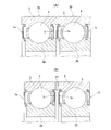
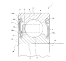
- FIG. 1A is a partial cross-sectional view showing a first example of an embodiment of the present invention
- FIG. 1B is an enlarged view of part a in FIG.
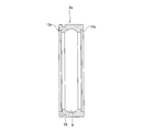
- FIG. 2A is a partial cross-sectional view of a seal ring for explaining a preferable shape of a seal lip when the present invention is carried out
- FIG. 2B is an enlarged view of a portion b of FIG. It is a figure (B).
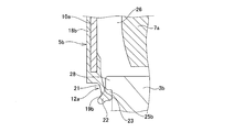
- 3A is a partial cross-sectional view (A) of a structure in which the dimensions of the protrusions constituting the seal ring are different from the structure shown in FIG. 1, and FIG. It is the c section enlarged view (B) of (A).
- FIG. 1A is a partial cross-sectional view showing a first example of an embodiment of the present invention
- FIG. 1B is an enlarged view of part a in FIG.
- FIG. 2A is a partial cross-sectional view of a seal ring for explaining a preferable shape of a seal lip
- FIG. 4A is a partial cross-sectional view showing one example of a state in which a plurality of rolling bearings with seal rings are conveyed in an axial direction with respect to the first example, and FIG. 4B is another example thereof.
- FIG. FIG. 5 is a cross-sectional view for explaining a preferable dimensional relationship of the outer ring when the present invention is carried out.
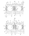
- FIG. 6 is a view similar to FIG. 1B, showing a second example of the embodiment of the present invention.
- FIG. 7 is a view similar to FIG. 1B, showing a third example of the embodiment of the present invention.
- FIG. 8A is a partial cross-sectional view showing an example of a state in which a plurality of rolling bearings with seal rings are conveyed in an axial direction in the fourth example of the embodiment of the present invention.
- B) is a partial cross-sectional view showing another example.
- FIG. 9 is a partial cross-sectional view showing an example of a conventional structure.
- the rolling bearing with seal ring of this example includes an outer ring 2 provided with an outer ring raceway 8 on the inner peripheral surface, an inner ring raceway 9 provided on the outer peripheral surface, and an inner ring 3a disposed concentrically with the outer ring 2 on the inner diameter side of the outer ring 2.
- a plurality of rolling elements 4 are arranged in an annular shape in a bearing inner space 26 formed between the outer ring 2 and the inner ring 3a, and arranged in a freely rolling manner between the inner ring raceway 9 and the outer ring raceway 8.
- a locking portion 11a that is provided at an outer peripheral edge that is one peripheral edge of the inner and outer peripheral edges, and is locked to at least one end of the outer ring 2, and the other peripheral edge of the inner and outer peripheral edges.
- a seal ring 5a having a seal lip 12a made of an elastic material provided on the inner peripheral edge.
- the tip edge of the seal lip 12a has a stepped surface 14a provided on the outer peripheral surface of one end of the inner ring 3 as in the structure shown in FIG. 9 or one end of the inner ring as in other conventional structures. It is in sliding contact with one end surface 24 of the inner ring 3a, not the outer peripheral surface (cylindrical surface). With this configuration, the seal ring 5a separates the bearing internal space 26 and the external space.
- the basic configuration of the rolling bearing with a seal ring of the present invention including this example is almost the same as that of the conventional structure shown in FIG. 9, the explanation for the equivalent parts is omitted or simplified.
- a corrugated press retainer is used as the retainer 7a for retaining the balls 4 in a freely rollable manner.
- Conventionally known cages of various structures such as cages and saddle cages can also be used.
- the structure of this example is not limited to the single row deep groove type ball bearing as shown in the figure, but can also be applied to double row ball bearings, angular type ball bearings, cylindrical roller bearings, tapered roller bearings, and spherical roller bearings. It is.
- the axial dimension of the inner ring 3a is shorter than the axial dimension of the outer ring 2.
- the axial end face 24 (the left end face in FIG. 1) of the inner ring 3a is recessed in the axial direction from the axial end face of the outer ring 2, that is, rolling with a seal ring. It exists in the axially central portion of the bearing 1a.
- the dimension W in which the one end surface 24 of the inner ring 3a is recessed in the axial direction center side of the rolling bearing 1a with the seal ring from the one end surface of the outer ring 2 is not particularly restricted.
- this dimension W is regulated so that the seal ring 5a does not protrude outward in the axial direction from one end face of the outer ring 2 in a state where the seal ring 5a is assembled and the seal lip 12a is elastically deformed. It is preferable.
- the other axial end surfaces (the right end surface in FIG. 1) of the inner ring 3a and the outer ring 2 are substantially on the same plane except for minute manufacturing errors.
- the outer peripheral edge of the seal ring 5a is locked to one locking groove 13a, and the other An outer peripheral edge portion (second locking portion) of the seal ring 5 that is basically the same as the conventional structure shown in FIG. 9 is locked in the locking groove (second locking groove) 13b.
- a seal ring similar to the seal ring 5a assembled to one locking groove 13a can be assembled to the other locking groove 13b. If the entry path of foreign matter is limited only from one end side, a non-contact type shield ring is assembled in the other locking groove 13b, or the seal ring and shield ring on the other end side are omitted. You can also.
- the feature of the present invention is that the tip edge of the seal lip constituting at least one axial end seal ring attached to one bearing ring (the outer ring 2 in the illustrated example) is connected to the other bearing ring (in the illustrated example).
- the structure on the other end side in the axial direction is arbitrary depending on the application of the rolling bearing with seal ring.
- the structure of assembling these seal rings to one of the race rings is as follows.
- the locking grooves 13a and 13c formed on the inner peripheral surfaces of both ends of the outer ring 2a whose shape is asymmetric with respect to the axial direction, the locking grooves 13a and 13c
- the inner diameter of the seal ring is made different so that a seal ring other than the seal ring that should be properly assembled cannot be assembled.
- the inner diameter of the outer ring 2a is about 50 to 70 mm
- the inner diameters of the locking grooves 13a and 13c are varied by about 1 to 2 mm, it is possible to prevent an unauthorized seal ring from being assembled in the locking grooves 13a and 13c. be able to.
- the difference between the inner diameters of the locking grooves 13a and 13c is preferably as small as possible to prevent erroneous assembly.
- different colors of the elastic members constituting different types of seal rings are also effective in preventing erroneous assembly.
- the inner diameters of the locking grooves 13a and 13c are different from each other, as shown in FIG.
- any one of the locking grooves 13a and 13c constitutes a second locking groove, and is provided on the outer peripheral edge of the second seal ring in the second locking groove.
- the tip end edge of the second seal lip made of an elastic material provided on the inner peripheral edge of the second seal ring is in sliding contact with a part of the inner ring 3a.
- the seal ring 5a is made of an elastic material 18a made of an elastomer such as rubber, which is made of a metal plate and reinforced by a ring-shaped cored bar 10a, and has an elastic locking portion 11a at the outer peripheral edge and a seal lip at the inner peripheral edge. 12a is formed in a state protruding in the radial direction from the outer peripheral edge or inner peripheral edge of the cored bar 10a.
- the structure of the elastic locking portion 11a is the same as the conventional structure shown in FIG. 9, while the seal lip 12a is different from the conventional structure shown in FIG.
- a protrusion 20 for constituting the labyrinth seal 19 is formed on the elastic member 18a in a portion protruding radially inward from the inner peripheral edge of the cored bar 10a.
- Each is provided over the entire circumference so as to protrude toward the surface of the inner ring 3a.
- the seal lip 12a includes a thick portion 22 having a thickness dimension larger than that of the connecting portion 21 on the inner peripheral edge portion of the plate-like connecting portion 21 constituting a radially central portion (radially outward) portion. It is provided over the circumference.
- the tip edge of the seal lip 12a is connected to the inner ring 3a.
- the one end surface 24 is in sliding contact with the entire circumference.
- the one end surface 24 of the inner ring 3a is a highly smooth surface having an arithmetic average surface roughness Ra of 1.0 ⁇ m or less. This stabilizes the sliding contact state between the one end surface 24 and the tip edge of the seal lip 12a (sliding contact edge 23 of the thick wall portion 22), improves the sealing performance by the seal lip 12a, and improves the sealing lip 12a.
- the tip edge wear is suppressed.
- the one end surface 24 of the inner ring 3a is a flat surface exposed to the outside, grinding for making the one end surface 24 a highly smooth surface is easy. That is, in the case of the conventional structure shown in FIG. 9, the stepped surface 14 a that slides the tip edge of the seal lip 12 is provided on the outer peripheral surface of the inner ring 3 in a state of being recessed radially inward. It is difficult to finish the stepped surface 14a to a highly smooth surface by ordinary side grinding. On the other hand, in the case of the structure of the present invention, the grinding process for making the one end surface 24 into a highly smooth surface can be performed easily and at low cost by ordinary side grinding.
- acrylic rubber is preferable in consideration of heat resistance up to about 130 ° C.
- NBR low cost nitrile rubber
- VMQ silicone rubber
- FKM fluoro rubber
- a protrusion 20 for constituting the labyrinth seal 19 is formed on the elastic member 18a in a portion protruding radially inward from the inner peripheral edge of the cored bar 10a.
- the protruding portion 20 is a part of the seal ring 5a that is a portion closer to the center in the radial direction (a portion closer to the outer side in the radial direction) than the connecting portion 21 of the seal lip 12a.
- the labyrinth seal 19 is formed between the protrusion 20 and a part of the inner ring 3a.
- the protrusion 20 has an inner diameter R 12 (D 3 ⁇ R 12 ) that is slightly larger than the outer diameter D 3 of the end (shoulder) of the inner ring 3a.
- the inner diameter R 10 of the metal core 10a is larger than the outer diameter D 3 of the axial end portion of the inner ring 3a (shoulder) and (R 10> D 3), includes a seal lip 12a, the elastic member 18a The degree of freedom of elastic deformation of the portion near the inner diameter is secured.
- the shapes and dimensional relationships of the seal lip 12a, the connecting portion 21, and the protruding portion 20 are regulated as follows.
- the sliding contact edge 23 is as shown in FIG. And exists on the chain line ⁇ .
- the leading edge of the protrusion 20 exists on the chain line ⁇ in FIG. That is, in the free state of the seal lip 12 a, the sliding contact edge 23 protrudes toward the inner ring 3 a side with respect to the axial direction from the tip edge of the protrusion portion 20.
- the thickness T 21 of the connecting portion 21 1/8 or more of the thickness T 22 of the thick portion 22, and a 1/3 or less (T 22/8 ⁇ T 21 ⁇ T 22/3).
- the thickness T 21 of the connecting portion 21 by regulating in this range, while securing the followability of the seal lips 12a, it is possible to realize a low torque.
- the angle ⁇ formed by the connecting portion 21 and the one end surface 24 (radial direction) of the inner ring 3a in the free state of the seal lip 12a is 0 degree or more, 45 It is preferable to regulate to a degree or less (0 ° ⁇ ⁇ ⁇ 45 °).
- the angle ⁇ is larger than 45 degrees ( ⁇ > 45 °), the surface pressure of the sliding contact portion between the sliding contact edge 23 and the one end surface 24 may increase.
- the sliding contact edge 23 is the inner ring 3a in a state where the connecting portion 21 of the seal lip 12a is elastically deformed.
- the one end surface 24 is pressed over the entire circumference based on the elasticity of the connecting portion 21.
- the leading edge of the ridge portion 20 is located on the axially central side of the inner ring 3 a with respect to the one end surface 24.
- the tip edge of the ridge portion 20 and the corner portion of the inner ring 3a are close to each other.
- a gap portion serving as the labyrinth seal 19 is formed over the entire circumference between the tip edge of the protrusion 20 and the corner of the inner ring 3a. Further, a space portion 25 having a larger width dimension than the labyrinth seal 19 exists between the labyrinth seal 19 and the sliding contact edge 23 in the radial direction and between the connecting portion 21 and the one end surface 24 in the axial direction. It becomes a state. The presence of the space portion 25 can increase the sealing effect of the labyrinth seal 19.
- the diameter of the sliding contact edge 23 is low in torque while preventing interference with other members such as a retaining ring 17 for positioning the rolling bearing 1a with a seal ring with respect to the shaft 15, and ensuring necessary sealing performance. It is regulated from the aspect of realizing. That is, the smaller the diameter D 23 of the sliding contact edge 23 is, the lower the frictional resistance (dynamic torque) generated at the sliding contact portion between the sliding contact edge 23 and the one end surface 24 is reduced. Dynamic torque reduction effect by reducing the diameter D 23 of Surise'en 23, conventional structure and smaller than the diameter D 12 of the sliding portion of the same leading edge of the seal lip 12 of the seal ring 5 and the stepped surface 14b ( If D 23 ⁇ D 12 ), it cannot be obtained.
- a positioning member that regulates the axial position of the inner ring 3 a such as the retaining ring 17 is abutted against the one end surface 24.
- the positioning member projects into a portion of the inner ring 3a having a high axial rigidity, specifically, a portion closer to the inner diameter than the groove bottom portion of the deep groove type inner ring raceway 9 formed on the outer peripheral surface of the inner ring 3a. It is enough to hit. In other words, it is meaningless to have the positioning member located radially outside the bottom of the groove.
- the diameter D 23 of Surise'en 23 is made larger than the diameter D 9 of the groove bottom portion of the inner ring raceway 9 (D 23> D 9) , an inner peripheral edge of the positioning member and the seal lip 12a Interference can be prevented. Therefore, the diameter D 23 of Surise'en 23, in relation to the groove bottom diameter D 9 and the seal ring 5a seal lip 12a leading edge and the diameter D 12 of the sliding portion of the stepped surface 14b of the inner ring raceway 9, It is preferable to be regulated such that D 9 ⁇ D 23 ⁇ D 12 .
- the inner diameter of the protrusion 20 is made slightly larger than the outer diameter of the axial end (shoulder) of the inner ring 3a, and the axial height of the protrusion 20 is increased.
- the directional thickness can be made sufficiently small.
- the outer diameter and the axial height of the protrusion 20 are made smaller than those in the structure shown in FIG.
- a corner portion of the shoulder portion of the inner ring 3a are closely opposed to each other, and this portion is used as a labyrinth seal 19.
- a chamfering (R chamfering) whose cross-sectional shape is a quarter arc is applied to a corner portion where the one end surface 24 of the inner ring 3a and the outer peripheral surface of the shoulder portion are continuous, and the elastic member 18a is connected to the corner portion. Even if they are rubbed together, the elastic material 18a is prevented from being damaged.
- the axial dimension of the installation space of the inner ring 3a relative to the shaft 15 can be shortened while ensuring the required sealing performance. That is, the axial dimension of the inner ring 3a is shorter than the axial dimension of the outer ring 2, and one axial end side of the outer ring 2 protrudes (overhangs) in the axial direction from the inner ring 3a. In other words, the one end surface of the inner ring 3 a is present at a position that is recessed in the axial direction (a portion closer to the center in the axial direction) than the one end surface of the outer ring 2.
- the retaining ring 17 which is a member for positioning the inner ring 3a with respect to the shaft 15 can be disposed on the inner diameter side of the portion protruding from the one end surface 24 of the inner ring 3a at one axial end portion of the outer ring 2.
- the rotation support part incorporating the rolling bearing 1a with a seal ring can be configured in a small size.
- the sliding contact edge 23 of the seal lip 12a provided at the inner peripheral edge of the seal ring 5a that closes the axial one end opening of the bearing internal space 26 in which the ball 4 is installed is brought into sliding contact with the one end surface 24 of the inner ring 3a. Therefore, even when the axial dimension of the inner ring 3a is shortened, the required sealing performance can be ensured.
- the labyrinth seal 19 is provided between the portion outside the sliding contact edge 23 in the radial direction (near the center in the radial direction of the seal ring 5a) and the surface of the inner ring 3a, the sealing performance by the seal ring 5a is more sufficient. Can be secured.
- the diameter D 23 of the sliding contact edge 23 of the seal lip 12a is made smaller (D 23 ⁇ D 12) than the diameter D 12 of the sliding contact portion between the edge and the stepped surface of the sealing lip in the conventional structure.
- the outer half of the seal lip 12a is formed as a thin connecting portion 21, it is possible to achieve both necessary sealing performance and low torque at a high level. That is, since the bending rigidity of the connecting portion 21 is low, even when the outer ring 2 and the inner ring 3a are relatively displaced in the axial direction, the followability to the one end surface 24 of the sliding contact edge 23 is improved, and a gap is formed between them. Even when the tightening margin (the amount of elastic deformation of the seal lip 12a) in the state in which the sliding contact edge 23 is in sliding contact with the one end surface 24 is increased, the sliding contact portion 23 Surface pressure can be kept low.
- the rolling bearing 1a with a seal ring is incorporated into, for example, a rotation support portion of a transmission, the wear torque or the like into the rolling bearing 1a with a seal ring is suppressed while keeping the dynamic torque of the rolling bearing 1a with a seal ring low. It is possible to sufficiently prevent foreign matter from entering.
- the seal lip 12a exists in a portion protruding in the axial direction from the one end surface 24 of the inner ring 3a.
- the seal ring 5a including the seal lip 12a is more axial than the one end in the axial direction of the outer ring 2. It does not protrude in the direction. Therefore, when a large number of rolling bearings 1a with seal rings are transported from a manufacturing factory for rolling bearings 1a with seal rings to an assembly factory such as a transmission, as shown in FIG. Even if they are stacked in the direction, the seal ring 5a does not interfere with a part of the adjacent rolling bearing with seal ring 1a, and damage to the seal ring 5a can be prevented.
- FIG. 6 shows a second example of the embodiment of the present invention.
- a protruding shoulder portion 28 having a substantially rectangular cross-sectional shape is formed over the entire circumference at the radially outer end portion of one end surface of the inner ring 3b. Then, the protruding shoulder portion 28 is formed on the protruding portion 20 and the thick portion 22 at the tip of the seal lip 12a in the inner surface (the surface facing the bearing internal space 26) of the elastic member 18a constituting the seal ring 5a.
- Labyrinth seals 19a and 19b are provided at two positions in the radial direction of the portion where the protruding shoulder portion 28 and the concave groove-shaped portion of the seal lip 12a face each other. .
- the portion between the labyrinth seals 19a, 19b is a space portion 25a having a width dimension larger than that of the labyrinth seals 19a, 19b, and the portion between the ridge shoulder portion 28 and the thick portion 22 is also the labyrinth seal 19a,
- the space portion 25b has a width dimension larger than that of the 19b portion.
- a pair of labyrinth seals 19a and 19b are provided in series with the contact-type seal portion by the sliding contact edge 23 of the thick portion 22 between the bearing inner space 26 and the outer space. ing. For this reason, it is possible to improve the sealing performance while suppressing an increase in the dynamic torque of the rolling bearing with a seal ring.
- the inner and outer peripheral edges of the front end surface of the ridge shoulder 28 are chamfered with an arc-shaped cross section, and even if the ridge shoulder 28 and the elastic member 18a rub against each other, the elastic member 18a. To prevent damage.
- the arithmetic average surface roughness Ra of the inner diameter portion of the inner ring 3b closer to the inner diameter than the protruding shoulder portion 28 is a highly smooth surface of 1.0 ⁇ m or less.
- the tip end surface and the inner peripheral surface of the ridge shoulder 28 need not be a highly smooth surface.
- the configuration and operation of the other parts are the same as in the first example of the embodiment.
- FIG. 7 shows a third example of the embodiment of the present invention.
- This example is a modification of the second example of the embodiment.
- the protruding portion 20 is not provided on the inner surface of the elastic member 18b constituting the seal ring 5b.
- the structure of this example is inferior in sealing performance as compared to the structure of the second example, but sufficient sealing performance can be obtained unless it is a part that requires particularly high sealing performance. Further, the manufacturing cost of the seal ring 5b can be kept low by the amount of the protrusion 20 omitted.
- the configuration and operation of the other parts are the same as in the second example of the embodiment.
- FIG. 8 shows a fourth example of the embodiment of the present invention and its modification.
- the one end surface 24 in the axial direction of the inner ring 3a is recessed in the axial direction from the one end surface in the axial direction of the outer ring 2b.
- the dimension w is regulated so that the seal ring 5 assembled at the other axial end of the rolling bearing 1b with the seal ring does not protrude outward in the axial direction from the other end surface of the inner ring 3a.
- the diameter of the inner peripheral edge of one end surface of the elastic member 18c is made larger than the outer diameter of the other end portion of the inner ring 3a.
- the diameter of the inner peripheral edge of the elastic member 18d is smaller than the outer diameter of the other end of the inner ring 3a.
- an annular spacer 27a is held between the adjacent outer rings 2b. Therefore, although the axial dimension in the state where the rolling bearing 1c with the seal ring is overlapped in the axial direction cannot be shortened, deterioration of the efficiency of the conveyance work can be minimized.
- the configuration and operation of the other parts are the same as in the first example of the embodiment.
Abstract
Description
図1~図5は、本発明の実施の形態の第1例およびその変形例を示している。本例のシールリング付き転がり軸受は、内周面に外輪軌道8を設けた外輪2と、外周面に内輪軌道9を設け、外輪2の内径側に外輪2と同心に配置された内輪3aと、外輪2と内輪3aとの間に形成された軸受内部空間内26で、内輪軌道9と外輪軌道8との間に転動自在に配置された複数個の転動体4と、円輪状に構成され、内外両周縁部のうちの一方の周縁部である外周縁部に設けられ、外輪2の少なくとも一端部に係止される係止部11aと、内外両周縁部のうちの他方の周縁部である内周縁部に設けられた弾性材製のシールリップ12aとを有する、シールリング5aを備える。本例では、このシールリップ12aの先端縁が、図9に示した構造のように、内輪3の一端部外周面に設けた段差面14aや、他の従来構造のように、内輪の一端部外周面(円筒面)ではなく、内輪3aの一端面24に摺接する。この構成により、シールリング5aは、軸受内部空間26と外部空間とを区分する。
図6は、本発明の実施の形態の第2例を示している。本例の場合には、内輪3bの一端面の径方向外端部に、断面形状が略矩形である突条肩部28を、全周にわたって形成している。そして、突条肩部28を、シールリング5aを構成する弾性材18aの内側面(軸受内部空間26に対向する面)のうちで、突条部20とシールリップ12aの先端の厚肉部22との間に存在する凹溝状部分に進入させて、突条肩部28とシールリップ12aの凹溝状部分とが対向する部分の径方向2箇所位置にラビリンスシール19a、19bを設けている。ラビリンスシール19a、19b同士の間部分は、ラビリンスシール19a、19b部分よりも幅寸法が大きくなった空間部分25aとし、突条肩部28と厚肉部22との間部分も、ラビリンスシール19a、19b部分よりも幅寸法が大きくなった空間部分25bとしている。
図7は、本発明の実施の形態の第3例を示している。本例は、実施の形態の第2例の変形例である。本例の場合、第2例と異なり、シールリング5bを構成する弾性材18bの内側面に、突条部20が設けられていない。本例の構造は、第2例の構造に比べればシール性能が劣るが、特に高度のシール性能を要求される部分でない限り、十分なシール性能を得られる。また、突条部20を省略した分、シールリング5bの製造コストを低く抑えることが可能である。その他の部分の構成および作用は、実施の形態の第2例と同様である。
図8は、本発明の実施の形態の第4例およびその変形例を示している。図8(A)に示す第4例の場合、シールリング付き転がり軸受1bを組み立てた状態で、内輪3aの軸方向の一端面24を、外輪2bの軸方向一端面よりも、軸方向に凹んだ位置に存在させる、すなわち、シールリング付き転がり軸受1bの軸方向中央寄り部分に位置させるとともに、外輪2bの軸方向他端面を、内輪3aの軸方向他端面よりも、軸方向に凹んだ位置に存在させる、すなわち、内輪3aの軸方向中央寄り部分に位置させている。そして、内輪3aの一端面24が外輪2bの一端面よりもシールリング付き転がり軸受1bの軸方向中央側に凹んでいる寸法Wを、外輪2bの他端面が内輪3aの他端面よりもシールリング付き転がり軸受1bの軸方向中央側に凹んでいる寸法wよりも大きくしている(W>w)。また、寸法Wを、シールリング付き転がり軸受1bの軸方向一端部に組み付けたシールリング5aが、外輪2bの一端面よりも軸方向外方に突出しない大きさに規制している。また、寸法wを、シールリング付き転がり軸受1bの軸方向他端部に組み付けたシールリング5が、内輪3aの他端面よりも軸方向外方に突出しない大きさに規制している。また、本例の場合には、弾性材18cの一端面内周縁の直径を、内輪3aの他端部の外径よりも大きくしている。
2、2a、2b 外輪
3、3a、3b 内輪
4 玉
5、5a、5b シールリング
6 シールドリング
7、7a 保持器
8 外輪軌道
9 内輪軌道
10、10a 芯金
11、11a 弾性係止部
12、12a シールリップ
13a~13c 係止溝
14a、14b 段差面
15 軸
16 係止溝
17 止め輪
18、18a、18b 弾性材
19、19a、19b ラビリンスシール
20 突条部
21 連結部
22 厚肉部
23 摺接縁
24、24a 一端面
25、25a、25b 空間部分
26 軸受内部空間
27、27a スペーサ
28 突条肩部
29 止め輪溝
Claims (15)
- 内周面に外輪軌道を設けた外輪と、
外周面に内輪軌道を設け、前記外輪の内径側に前記外輪と同心に配置された内輪と、
前記外輪と前記内輪との間に形成された軸受内部空間内で、前記内輪軌道と前記外輪軌道との間に転動自在に配置された複数個の転動体と、
円輪状に構成され、内外両周縁部のうちの一方の周縁部に設けられ、前記外輪および前記内輪のうちの一方の少なくとも一端部に係止される係止部と、前記内外両周縁部のうちの他方の周縁部に設けられ、先端縁が前記外輪および前記内輪のうちの他方の一端面に摺接する、弾性材製のシールリップとを有し、前記軸受内部空間と外部空間とを区分するシールリングと、
を備え、
前記シールリップは、前記先端縁よりも径方向中央寄り部分に形成された板状の連結部と、この連結部から連続し、前記連結部よりも大きな厚さ寸法を有する厚肉部とを備え、前記先端縁がこの厚肉部の軸方向端縁により構成される、
シールリング付き転がり軸受。 - 前記外輪および前記内輪のうちの他方の一端面のうちで、少なくとも前記シールリングの前記先端縁が摺接する部分の算術平均表面粗さRaが、1.0μm以下である、請求項1に記載のシールリング付き転がり軸受。
- 前記シールリングの一部で前記連結部よりも径方向中央寄り部分と、前記外輪および前記内輪のうちの他方の一部とが、非接触状態で対向して、これらの部分の間にラビリンスシールが形成されている、請求項1に記載のシールリング付き転がり軸受。
- 前記シールリングの前記径方向中央寄り部分が、前記シールリングの側面から前記外輪および前記内輪のうちの他方の表面に向けて突出するように形成された弾性材製の突条部により構成される、請求項3に記載のシールリング付き転がり軸受。
- 前記シールリングの前記係止部を、前記外輪および前記内輪のうちの一方に係止する以前の、前記シールリップの自由状態において、前記厚肉部の軸方向端縁が、前記突条部よりも、軸方向に関して前記外輪および前記内輪のうちの他方側に突出する、請求項4に記載のシールリング付き転がり軸受。
- 前記外輪および前記内輪のうちの他方の前記一部が、前記外輪および前記内輪のうちの他方の一端面から前記シールリングの径方向中央寄り部分に向けて突出するように形成された突条肩部により構成される、請求項3に記載のシールリング付き転がり軸受。
- 前記連結部の厚さ寸法が、前記厚肉部の厚さ寸法の1/8以上、1/3以下である、請求項1に記載のシールリング付き転がり軸受。
- 前記連結部と前記外輪および前記内輪のうちの他方の一端面とのなす角度が、0度以上、45度以下である、請求項1に記載のシールリング付き転がり軸受。
- 前記外輪および前記内輪のうちの他方の一端面が、前記外輪および前記内輪のうちの一方の一端面よりも、軸方向に凹んだ位置に存在している、請求項1に記載のシールリング付き転がり軸受。
- 前記係止部が前記外輪の一端部に係止され、前記シールリップの先端縁が前記内輪の一端面に摺接しており、前記内輪の一端面が、前記外輪の一端面よりも、軸方向に凹んだ位置に存在している、請求項1に記載のシールリング付き転がり軸受。
- 前記内輪の軸に対する位置決めを図るための部材が、前記外輪の一端部で、前記内輪の一端面よりも突出した部分の内径側に配置される、請求項10に記載のシールリング付き転がり軸受。
- 前記内輪の内輪軌道が深溝型の内輪軌道であり、前記シールリップの先端縁と前記内輪の一端面との摺接部の直径が、この内輪軌道の溝底径よりも大きい、請求項10に記載のシールリング付き転がり軸受。
- 前記シールリングが、前記シールリップを少なくとも構成する前記弾性材と、この弾性材を補強する金属板製で円輪状の芯金とにより構成され、前記芯金の内径が、前記内輪の外径よりも大きい、請求項10に記載したシールリング付き転がり軸受。
- 前記外輪の他端面が前記内輪の他端面よりも軸方向に凹んだ位置に存在しており、前記内輪の一端面が前記外輪の一端面よりも軸方向に凹んでいる寸法が、前記外輪の他端面が前記内輪の他端面よりも軸方向に凹んでいる寸法よりも大きい、請求項10に記載のシールリング付き転がり軸受。
- 前記係止部が前記外輪の一端部内周面に形成された係止溝に係止され、前記シールリップの先端縁が前記内輪の一端面に摺接しており、前記内輪の一端面が、前記外輪の一端面よりも、軸方向に凹んだ位置に存在しており、
円輪状に構成され、外周縁部に設けられ、前記外輪の他端部内周面に形成された係止溝に係止される第2の係止部と、内周縁部に設けられ、先端縁が前記内輪の一部に摺接する、弾性材製の第2のシールリップとを有し、前記軸受内部空間と前記外部空間とを区分する、第2のシールリングをさらに備え、
第2のシールリングの第2の係止部および第2の係止溝の直径を、前記シールリングの前記係止部および前記係止溝の直径と異ならせることで、前記シールリングと第2のシールリングとの誤組付けの防止が図られている、請求項1に記載のシールリング付き転がり軸受。
Priority Applications (5)
| Application Number | Priority Date | Filing Date | Title |
|---|---|---|---|
| EP12820816.2A EP2746608B1 (en) | 2011-08-03 | 2012-08-02 | Rolling bearing with seal ring |
| US14/236,768 US9316259B2 (en) | 2011-08-03 | 2012-08-02 | Rolling bearing with seal ring |
| CN201280036688.8A CN103717931B (zh) | 2011-08-03 | 2012-08-02 | 带密封环的滚动轴承 |
| JP2013526956A JP5765424B2 (ja) | 2011-08-03 | 2012-08-02 | シールリング付き転がり軸受 |
| US15/064,015 US9523390B2 (en) | 2011-08-03 | 2016-03-08 | Rolling bearing with seal ring |
Applications Claiming Priority (6)
| Application Number | Priority Date | Filing Date | Title |
|---|---|---|---|
| JP2011-169812 | 2011-08-03 | ||
| JP2011169812 | 2011-08-03 | ||
| JP2012-127847 | 2012-06-05 | ||
| JP2012127847 | 2012-06-05 | ||
| JP2012157576 | 2012-07-13 | ||
| JP2012-157576 | 2012-07-13 |
Related Child Applications (2)
| Application Number | Title | Priority Date | Filing Date |
|---|---|---|---|
| US14/236,768 A-371-Of-International US9316259B2 (en) | 2011-08-03 | 2012-08-02 | Rolling bearing with seal ring |
| US15/064,015 Continuation US9523390B2 (en) | 2011-08-03 | 2016-03-08 | Rolling bearing with seal ring |
Publications (1)
| Publication Number | Publication Date |
|---|---|
| WO2013018865A1 true WO2013018865A1 (ja) | 2013-02-07 |
Family
ID=47629381
Family Applications (1)
| Application Number | Title | Priority Date | Filing Date |
|---|---|---|---|
| PCT/JP2012/069704 WO2013018865A1 (ja) | 2011-08-03 | 2012-08-02 | シールリング付き転がり軸受 |
Country Status (5)
| Country | Link |
|---|---|
| US (2) | US9316259B2 (ja) |
| EP (2) | EP2746608B1 (ja) |
| JP (2) | JP5765424B2 (ja) |
| CN (2) | CN105626683B (ja) |
| WO (1) | WO2013018865A1 (ja) |
Cited By (3)
| Publication number | Priority date | Publication date | Assignee | Title |
|---|---|---|---|---|
| JP2015014332A (ja) * | 2013-07-05 | 2015-01-22 | セイコーインスツル株式会社 | 軸受装置、軸受装置の製造方法および情報記録再生装置 |
| JP2015152030A (ja) * | 2014-02-10 | 2015-08-24 | Ntn株式会社 | 密封装置およびこれを備えた車輪用軸受装置 |
| JP2018070008A (ja) * | 2016-10-31 | 2018-05-10 | 株式会社ジェイテクト | ステアリング装置 |
Families Citing this family (9)
| Publication number | Priority date | Publication date | Assignee | Title |
|---|---|---|---|---|
| DE102013215962A1 (de) * | 2013-08-13 | 2015-03-12 | Schaeffler Technologies AG & Co. KG | Rundtischlager |
| EP3387293B1 (de) * | 2017-02-28 | 2021-08-25 | Harmonic Drive SE | Spannungswellengetriebe mit innendichtung |
| IT201700101128A1 (it) * | 2017-09-11 | 2019-03-11 | Skf Ab | Assieme di cuscinetto e guarnizione in combinazione con corpo esterno comune |
| US11313469B2 (en) * | 2018-02-27 | 2022-04-26 | Nok Corporation | Sealing structure |
| DE102018106192A1 (de) * | 2018-03-16 | 2019-09-19 | Maschinenfabrik Gustav Eirich Gmbh & Co. Kg | Mischvorrichtung mit zweiteiligem Verschlussdeckel |
| CN108808971B (zh) * | 2018-06-12 | 2019-10-08 | 赵文龙 | 一种提高电机使用寿命的方法 |
| CN108518421B (zh) * | 2018-06-12 | 2019-08-16 | 柯拉思利工业科技(上海)有限公司 | 一种密封轴承 |
| JP7281422B2 (ja) * | 2020-01-15 | 2023-05-25 | 株式会社シマノ | 釣り用リール |
| CN114635925B (zh) * | 2022-02-23 | 2024-02-13 | 清华大学 | 基于表面织构的磁性液体密封装置 |
Citations (9)
| Publication number | Priority date | Publication date | Assignee | Title |
|---|---|---|---|---|
| DE20306004U1 (de) | 2003-04-15 | 2003-07-03 | Skf Ab | Lageranordnung |
| JP2004144107A (ja) * | 2002-10-21 | 2004-05-20 | Nsk Ltd | 転がり軸受密封装置 |
| JP2006226459A (ja) * | 2005-02-18 | 2006-08-31 | Nsk Ltd | 転がり軸受 |
| JP2006283782A (ja) * | 2005-03-31 | 2006-10-19 | Jtekt Corp | 転がり軸受の密封装置 |
| JP2007270969A (ja) * | 2006-03-31 | 2007-10-18 | Jtekt Corp | 転がり軸受 |
| JP2008232285A (ja) * | 2007-03-20 | 2008-10-02 | Jtekt Corp | 転がり軸受の密封装置 |
| JP2009191864A (ja) * | 2008-02-12 | 2009-08-27 | Nsk Ltd | 転がり軸受 |
| JP2010096218A (ja) * | 2008-10-14 | 2010-04-30 | Jtekt Corp | 軸受用シール装置 |
| WO2011051045A1 (de) | 2009-10-28 | 2011-05-05 | Schaeffler Technologies Gmbh & Co. Kg | Antriebseinheit für kraftfahrzeuge mit einem elektromotor |
Family Cites Families (17)
| Publication number | Priority date | Publication date | Assignee | Title |
|---|---|---|---|---|
| US1888215A (en) * | 1930-02-06 | 1932-11-22 | Norma Hoffmann Bearings Corp | Antifriction bearing |
| US1910061A (en) * | 1930-12-27 | 1933-05-23 | Fed Bearings Company Inc | Antifriction bearing |
| US1917988A (en) * | 1932-02-04 | 1933-07-11 | New Departure Mfg Co | Bearing and guard therefor |
| US2690362A (en) * | 1952-04-03 | 1954-09-28 | Jeffrey Mfg Co | Sealed roller bearing |
| US3870384A (en) * | 1972-09-15 | 1975-03-11 | Federal Mogul Corp | Preloading and sealing system for clutch bearings |
| US4505484A (en) * | 1980-03-12 | 1985-03-19 | Nippon Seiko Kabushiki Kaisha | Sealing device for a rolling bearing |
| JPS61135961U (ja) * | 1985-02-06 | 1986-08-23 | ||
| US4763905A (en) * | 1987-12-04 | 1988-08-16 | Allied-Signal Inc. | Seal retention and anti-rotation locking assembly |
| US5340124A (en) * | 1992-08-14 | 1994-08-23 | Allied-Signal Inc. | Seal retention and anti-rotation locking assembly |
| US5511886A (en) * | 1994-05-23 | 1996-04-30 | Brenco Incorporated | Bearing seal with oil deflectors |
| JP3740219B2 (ja) * | 1996-07-05 | 2006-02-01 | 光洋精工株式会社 | 転がり軸受の密封装置 |
| JP2003049855A (ja) * | 2001-08-07 | 2003-02-21 | Koyo Sealing Techno Co Ltd | 軸受用シールおよびこれを備える転がり軸受 |
| CN100400910C (zh) * | 2002-07-12 | 2008-07-09 | 日本精工株式会社 | 带轮支架的双列滚珠轴承 |
| JP2005163925A (ja) * | 2003-12-03 | 2005-06-23 | Koyo Seiko Co Ltd | 転がり軸受及びクラッチレリーズ軸受 |
| JP2007107588A (ja) * | 2005-10-12 | 2007-04-26 | Nsk Ltd | 転がり軸受 |
| DE102009034798A1 (de) * | 2009-07-25 | 2011-01-27 | Schaeffler Technologies Gmbh & Co. Kg | Wälzlager, insbesondere einreihiges Rillenkugellager für ein Zweimassenschwungrad in einem Kraftfahrzeug |
| JP2011106603A (ja) * | 2009-11-19 | 2011-06-02 | Ntn Corp | シール付き軸受 |
-
2012
- 2012-08-02 EP EP12820816.2A patent/EP2746608B1/en not_active Not-in-force
- 2012-08-02 US US14/236,768 patent/US9316259B2/en active Active
- 2012-08-02 CN CN201610039173.3A patent/CN105626683B/zh not_active Expired - Fee Related
- 2012-08-02 EP EP15190283.0A patent/EP3018376B1/en not_active Not-in-force
- 2012-08-02 JP JP2013526956A patent/JP5765424B2/ja not_active Expired - Fee Related
- 2012-08-02 WO PCT/JP2012/069704 patent/WO2013018865A1/ja active Application Filing
- 2012-08-02 CN CN201280036688.8A patent/CN103717931B/zh not_active Expired - Fee Related
-
2014
- 2014-11-18 JP JP2014233707A patent/JP5920443B2/ja not_active Expired - Fee Related
-
2016
- 2016-03-08 US US15/064,015 patent/US9523390B2/en not_active Expired - Fee Related
Patent Citations (9)
| Publication number | Priority date | Publication date | Assignee | Title |
|---|---|---|---|---|
| JP2004144107A (ja) * | 2002-10-21 | 2004-05-20 | Nsk Ltd | 転がり軸受密封装置 |
| DE20306004U1 (de) | 2003-04-15 | 2003-07-03 | Skf Ab | Lageranordnung |
| JP2006226459A (ja) * | 2005-02-18 | 2006-08-31 | Nsk Ltd | 転がり軸受 |
| JP2006283782A (ja) * | 2005-03-31 | 2006-10-19 | Jtekt Corp | 転がり軸受の密封装置 |
| JP2007270969A (ja) * | 2006-03-31 | 2007-10-18 | Jtekt Corp | 転がり軸受 |
| JP2008232285A (ja) * | 2007-03-20 | 2008-10-02 | Jtekt Corp | 転がり軸受の密封装置 |
| JP2009191864A (ja) * | 2008-02-12 | 2009-08-27 | Nsk Ltd | 転がり軸受 |
| JP2010096218A (ja) * | 2008-10-14 | 2010-04-30 | Jtekt Corp | 軸受用シール装置 |
| WO2011051045A1 (de) | 2009-10-28 | 2011-05-05 | Schaeffler Technologies Gmbh & Co. Kg | Antriebseinheit für kraftfahrzeuge mit einem elektromotor |
Non-Patent Citations (1)
| Title |
|---|
| See also references of EP2746608A4 |
Cited By (3)
| Publication number | Priority date | Publication date | Assignee | Title |
|---|---|---|---|---|
| JP2015014332A (ja) * | 2013-07-05 | 2015-01-22 | セイコーインスツル株式会社 | 軸受装置、軸受装置の製造方法および情報記録再生装置 |
| JP2015152030A (ja) * | 2014-02-10 | 2015-08-24 | Ntn株式会社 | 密封装置およびこれを備えた車輪用軸受装置 |
| JP2018070008A (ja) * | 2016-10-31 | 2018-05-10 | 株式会社ジェイテクト | ステアリング装置 |
Also Published As
| Publication number | Publication date |
|---|---|
| CN103717931A (zh) | 2014-04-09 |
| US9316259B2 (en) | 2016-04-19 |
| EP3018376B1 (en) | 2018-07-04 |
| CN105626683A (zh) | 2016-06-01 |
| JP2015072067A (ja) | 2015-04-16 |
| US20160186814A1 (en) | 2016-06-30 |
| CN105626683B (zh) | 2017-10-13 |
| JPWO2013018865A1 (ja) | 2015-03-05 |
| EP3018376A1 (en) | 2016-05-11 |
| US20140348455A1 (en) | 2014-11-27 |
| CN103717931B (zh) | 2016-11-09 |
| EP2746608A4 (en) | 2015-04-15 |
| US9523390B2 (en) | 2016-12-20 |
| JP5765424B2 (ja) | 2015-08-19 |
| JP5920443B2 (ja) | 2016-05-18 |
| EP2746608A1 (en) | 2014-06-25 |
| EP2746608B1 (en) | 2016-10-19 |
Similar Documents
| Publication | Publication Date | Title |
|---|---|---|
| JP5920443B2 (ja) | シールリング付き転がり軸受 | |
| US8226298B2 (en) | Sealing device and rolling bearing apparatus | |
| JP2010190241A (ja) | 自動調心ころ軸受 | |
| JP5835199B2 (ja) | 玉軸受 | |
| JP6532651B2 (ja) | シールリング付転がり軸受 | |
| JP2014109369A5 (ja) | ||
| JP2011144899A (ja) | 複列転がり軸受 | |
| US20160169287A1 (en) | Rolling bearing comprising a sealing flange | |
| JP2007333011A (ja) | 深溝玉軸受 | |
| JP5326358B2 (ja) | 密封型転がり軸受 | |
| JP2015021567A (ja) | 複列軸受 | |
| WO2020166686A1 (ja) | 転がり軸受 | |
| JP6981143B2 (ja) | シール付き玉軸受 | |
| JP5581719B2 (ja) | スラストころ軸受 | |
| JP2008133885A (ja) | 組み合わせ転がり軸受 | |
| JP2016023727A (ja) | 転がり軸受の密封装置及び転がり軸受 | |
| JP7306136B2 (ja) | 深溝玉軸受 | |
| JP2010090986A (ja) | 密封型転がり軸受 | |
| JP7141199B2 (ja) | 車輪用軸受装置 | |
| JP2021001633A (ja) | 転がり軸受 | |
| JP2013167316A (ja) | 密封型転がり軸受 | |
| JP2008157370A (ja) | フォロア軸受 | |
| JP2008019999A (ja) | 密封転がり軸受 | |
| JP3132372U (ja) | 密封自動調心軸受 | |
| JP2021089046A (ja) | シェル形ニードル軸受 |
Legal Events
| Date | Code | Title | Description |
|---|---|---|---|
| 121 | Ep: the epo has been informed by wipo that ep was designated in this application |
Ref document number: 12820816 Country of ref document: EP Kind code of ref document: A1 |
|
| ENP | Entry into the national phase |
Ref document number: 2013526956 Country of ref document: JP Kind code of ref document: A |
|
| NENP | Non-entry into the national phase |
Ref country code: DE |
|
| REEP | Request for entry into the european phase |
Ref document number: 2012820816 Country of ref document: EP |
|
| WWE | Wipo information: entry into national phase |
Ref document number: 2012820816 Country of ref document: EP |
|
| WWE | Wipo information: entry into national phase |
Ref document number: 14236768 Country of ref document: US |