WO2013018436A1 - 吸収性物品の製造方法 - Google Patents
吸収性物品の製造方法 Download PDFInfo
- Publication number
- WO2013018436A1 WO2013018436A1 PCT/JP2012/064682 JP2012064682W WO2013018436A1 WO 2013018436 A1 WO2013018436 A1 WO 2013018436A1 JP 2012064682 W JP2012064682 W JP 2012064682W WO 2013018436 A1 WO2013018436 A1 WO 2013018436A1
- Authority
- WO
- WIPO (PCT)
- Prior art keywords
- wing member
- absorbent article
- continuum
- manufacturing
- continuous body
- Prior art date
Links
Images


Classifications
-
- A—HUMAN NECESSITIES
- A61—MEDICAL OR VETERINARY SCIENCE; HYGIENE
- A61F—FILTERS IMPLANTABLE INTO BLOOD VESSELS; PROSTHESES; DEVICES PROVIDING PATENCY TO, OR PREVENTING COLLAPSING OF, TUBULAR STRUCTURES OF THE BODY, e.g. STENTS; ORTHOPAEDIC, NURSING OR CONTRACEPTIVE DEVICES; FOMENTATION; TREATMENT OR PROTECTION OF EYES OR EARS; BANDAGES, DRESSINGS OR ABSORBENT PADS; FIRST-AID KITS
- A61F13/00—Bandages or dressings; Absorbent pads
- A61F13/15—Absorbent pads, e.g. sanitary towels, swabs or tampons for external or internal application to the body; Supporting or fastening means therefor; Tampon applicators
- A61F13/45—Absorbent pads, e.g. sanitary towels, swabs or tampons for external or internal application to the body; Supporting or fastening means therefor; Tampon applicators characterised by the shape
- A61F13/47—Sanitary towels, incontinence pads or napkins
- A61F13/472—Sanitary towels, incontinence pads or napkins specially adapted for female use
-
- A—HUMAN NECESSITIES
- A61—MEDICAL OR VETERINARY SCIENCE; HYGIENE
- A61F—FILTERS IMPLANTABLE INTO BLOOD VESSELS; PROSTHESES; DEVICES PROVIDING PATENCY TO, OR PREVENTING COLLAPSING OF, TUBULAR STRUCTURES OF THE BODY, e.g. STENTS; ORTHOPAEDIC, NURSING OR CONTRACEPTIVE DEVICES; FOMENTATION; TREATMENT OR PROTECTION OF EYES OR EARS; BANDAGES, DRESSINGS OR ABSORBENT PADS; FIRST-AID KITS
- A61F13/00—Bandages or dressings; Absorbent pads
- A61F13/15—Absorbent pads, e.g. sanitary towels, swabs or tampons for external or internal application to the body; Supporting or fastening means therefor; Tampon applicators
- A61F13/15577—Apparatus or processes for manufacturing
- A61F13/15756—Applying tabs, strips, tapes, loops; Knotting the ends of pads
-
- A—HUMAN NECESSITIES
- A61—MEDICAL OR VETERINARY SCIENCE; HYGIENE
- A61F—FILTERS IMPLANTABLE INTO BLOOD VESSELS; PROSTHESES; DEVICES PROVIDING PATENCY TO, OR PREVENTING COLLAPSING OF, TUBULAR STRUCTURES OF THE BODY, e.g. STENTS; ORTHOPAEDIC, NURSING OR CONTRACEPTIVE DEVICES; FOMENTATION; TREATMENT OR PROTECTION OF EYES OR EARS; BANDAGES, DRESSINGS OR ABSORBENT PADS; FIRST-AID KITS
- A61F13/00—Bandages or dressings; Absorbent pads
- A61F13/15—Absorbent pads, e.g. sanitary towels, swabs or tampons for external or internal application to the body; Supporting or fastening means therefor; Tampon applicators
- A61F13/56—Supporting or fastening means
- A61F13/5605—Supporting or fastening means specially adapted for sanitary napkins or the like
- A61F13/5616—Supporting or fastening means specially adapted for sanitary napkins or the like using flaps, e.g. adhesive, for attachment to the undergarment
Definitions
- the present invention relates to a method for manufacturing an absorbent article.
- a method for manufacturing an absorbent article wherein the absorbent article is composed of a top sheet, a back sheet, a main body including an absorbent core disposed between the top sheet and the back sheet, and a member separate from the main body.
- a wing member joined to the wing member, and the wing member includes projecting portions respectively projecting from both side edges of the main body, and the manufacturing method cuts the wing member raw material sheet along the cutting line, whereby the wing member continuous body Forming a wing member by cutting the wing member continuous body in a transverse direction, and joining the wing member to the top sheet continuous body or the back sheet continuous body at intervals in the conveying direction.
- the wing member is formed by supplying the wing member continuous body between the cutter roll and the anvil roll.
- the peripheral speed of the cutter roll and the anvil roll is made larger than the conveying speed of the wing member continuous body, and slip occurs between the cutter roll and the anvil roll and the wing member continuous body.
- the wing members are conveyed at intervals in the conveying direction.
- the wing member continuum includes protruding portions of the wing member, and these protruding portions are also transported between the cutter roll and the anvil roll.
- the protruding portion can move relatively freely. For this reason, there exists a possibility that a wing member continuous body or a wing member may bend
- the absorbent article includes a top sheet, a back sheet, a main body including an absorbent core disposed between the top sheet and the back sheet, and a separate body from the main body.
- a wing member composed of a member and joined to the main body, the wing member including projecting portions respectively projecting from both side edges of the main body, each of the projecting portions for fixing the absorbent article to the garment
- An adhesive part and a separator covering the adhesive part are provided, and the manufacturing method cuts the wing member raw material sheet along a cutting line, thereby forming a wing member continuous body partially connected to the trim And forming an adhesive portion on the protruding portion of the wing member continuous body, and forming an adhesive portion located on one side of the wing member continuous body and the other side of the wing member continuous body.
- a manufacturing method including: a separation step of forming a wing member having an adhesive portion and a separator; and a bonding step of bonding the wing member to the top sheet continuous body or the back sheet continuous body at intervals in the transport direction. Is done.
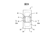
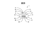
- FIG. 2B is a cross-sectional view taken along line IIB-IIB in FIG. 2A.
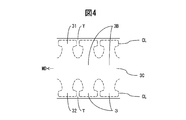
- Method of manufacturing an absorbent article is a schematic view showing a. It is a partial plan view taken along arrow IV of FIG. It is a partial plan view taken along arrow V of FIG. It is a partial plan view taken along arrow VIA of Fig.
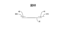
- FIG. 6B is a cross-sectional view taken along line VIB-VIB of FIG. 6A.
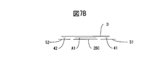
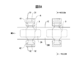
- FIG. 7B is a cross-sectional view taken along line VIIB-VIIB in FIG. 7A. It is a partial plan view taken along an arrow VIIIA in Fig.
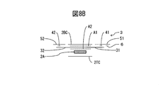
- FIG. 8B is a cross-sectional view taken along line VIIIB-VIIIB in FIG. 8A. It is a plan view similar to Figure 1A showing another example of the protruding portion.
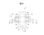
- the absorbent article 1 includes a main body 2 and a wing member 3 composed of a member different from the main body 2 and joined to the main body 2.
- the absorbent article 1 includes a sanitary napkin, an incontinence pad, a panty liner, and the like.
- the main body 2 includes a liquid-permeable top sheet 2T, a liquid-impermeable back sheet 2B, and a liquid-retaining absorbent core 2A disposed between the top sheet 2T and the back sheet 2B.
- the top sheet 2T is made of, for example, a non-woven fabric
- the back sheet 2B is made of, for example, a non-woven fabric or a plastic film.
- the absorbent core 2A is composed of an aggregate such as pulp or synthetic fiber and a superabsorbent polymer.
- the wing member 3 includes a base portion 3B joined to the main body 2 and first and second protruding portions 31 and 32 that protrude from both side edges 2L and 2L of the main body 2, respectively. Concave grooves 3D and 3D are formed on both side portions of the projecting portions 31 and 32, and accordingly, enlarged tip portions 3E are formed on the projecting portions 31 and 32.
- the protruding portions 31 and 32 are respectively provided with first and second adhesive portions 41 and 42 for fixing the absorbent article 1 to clothing such as underwear, and first and second covering the adhesive portions 41 and 42. a separator or release paper 51 and 52, are provided.
- Adhesive portion 41, 42 for example, a hot melt adhesive.
- the wing member 3 is, for example, a film (polyethylene, polypropylene, etc.), a nonwoven fabric (including fibers such as polyolefin, polyethylene terephthalate, spunbond nonwoven fabric, spunbond / meltblown / spunbond nonwoven fabric, air-through nonwoven fabric, point bond nonwoven fabric, spunlace nonwoven fabric, etc. ), and a composite of film and nonwoven fabric.
- the skin contact surface side of the wing member 3 is preferably made of a nonwoven fabric, that is, preferably made of the nonwoven fabric or a composite material of a film and a nonwoven fabric.
- the separators 51 and 52 are made of a base material that has been subjected to a surface treatment that can be peeled off from the adhesive portions 41 and 42 disposed on the wing member 3.
- the substrate is made of, for example, a film (polyethylene, polypropylene, polyethylene terephthalate, etc.) or paper.
- the surface treatment can be performed by applying a normal thermosetting or ultraviolet curable silicone to the substrate and then curing it.
- the wing member 3 is disposed between the absorbent core 2A and the back sheet 2B.
- A1 is an adhesive between the back sheet 2B and the wing member 3, the absorbent core 2A, and the top sheet 2T
- A2 is an adhesive between the wing member 3, the absorbent core 2A, and the top sheet 2T.
- FIGS. 2A and 2B show a state in which the wing member 3 is folded. That is, the protruding portions 31 and 32 of the wing member 3 are folded and positioned on the topsheet 2T. Further, the separators 51 and 52 are joined to each other by the adhesive 6.
- the absorbent article 1 is packed in a package in such a folded state.
- the wearer first separates the separators 51 and 52 from each other and removes the separators 51 and 52 from the protruding portions 31 and 32.
- the absorbent article 1 is fixed to the clothing through the adhesive portions 41 and 42.
- FIG. 3 schematically shows a method for manufacturing the absorbent article 1.
- the wing member material sheet SR3 is rewound from the roll 3R and sent to the cutting device C1.
- the cutting device C1 includes a cutter roll and an anvil roll that rotate in opposite directions, and the wing member raw material sheet SR3 is supplied between the cutter roll and the anvil roll.
- the wing member raw material sheet 3S is cut along a predetermined cutting line.
- a wing member continuous body 3 ⁇ / b> C partially connected to the trim T is formed.
- the wing member continuous body 3 ⁇ / b> C includes a plurality of wing members 3 that are continuous with each other.
- the wing members 3 are continuous with each other in the base portion 3B, and the protruding portions 31 and 32 protrude outward on both sides of the wing member continuous body 3C.
- the wing member continuous body 3 ⁇ / b> C is sent to the superposing device 71 through the idle roll R ⁇ b> 1 together with the trim T.
- MD indicates a transport direction
- CL indicates a cutting line.
- the protruding portions 31 and 32 are connected to the trim T, and are prevented from moving freely. Therefore, the formation of wrinkles and the like in the wing member continuous body 3C is suppressed.
- the separator raw material sheet 5S is rewound from the roll 5R and sent to the cutting device C2.
- the cutting device C2 includes a cutter roll and an anvil roll that rotate in opposite directions, and the separator raw material sheet 5S is supplied between the cutter roll and the anvil roll.
- the separator raw material sheet 5S is cut along a cutting line parallel to the transport direction MD.
- first and second separator continuums 51C and 52C extending in the transport direction MD are formed.
- the first and second separator continuums 51C and 52C are sent to the stacking device 71 via the idle roll R2.
- the idle roll R2 the first and second separator continuums 51C and 52C are transported while being separated in the transverse direction orthogonal to the transport direction MD.
- the adhesive is applied intermittently by the adhesive applicator 70 to the first and second separator continuums 51C and 52C.
- the first and second separator continuums 51C and 52C are formed with adhesive portions 41 and 42 that are separated from each other in the transport direction MD, respectively.
- the wing member continuous body 3C and the first and second separator continuous bodies 51C and 52C are overlapped with each other in the overlapping device 71.
- the stacking device 71 is composed of a pair of rolls that rotate in opposite directions, and a wing member continuous body 3C and first and second separator continuous bodies 51C and 52C are supplied between these rolls.
- the adhesive portions 41 and 42 on the first and second separator continuous bodies 51C and 52C are overlapped with the protruding portions 31 and 32 of the wing member continuous body 3C.
- the trim T is removed from the wing member continuous body 3C. Specifically, the wing member continuous body 3C and the trim T are transported in different directions.
- adhesive portions 41 and 42 are formed on the protruding portions 31 and 32, respectively. Further, the first adhesive portion 41 is covered with the first separator continuum 51C, and the second adhesive portion 42 on the second protruding portion 32 is covered with the second separator continuum 52C.
- the first projecting portions 31 located on one side of the wing member continuous body 3C are connected to each other by the first separator continuous body 51C, and the second projecting portions 32 located on the other side of the wing member continuous body 3C. Are connected to each other by the second separator continuous body 52C. Accordingly, the first and second projecting portions 31 and 32 are restrained from moving freely. Therefore, the formation of wrinkles and the like in the wing member continuous body 3C is suppressed.
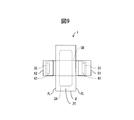
- the wing member continuous body 3C is then sent to the cutting device C3 via the idle roll R3.
- the cutting device C3 includes a cutter roll and an anvil roll that rotate in opposite directions, and the wing member continuous body 3C is supplied between the cutter roll 72C and the anvil roll 72A.
- the back sheet continuous body 2BC is rewound from the back sheet roll 2BR and sent to the anvil roll 72A of the cutting device C3 via the idle roll R4.
- the back surface sheet continuous body 2BC is composed of a plurality of back surface sheets 2B continuous with each other.
- the adhesive is intermittently applied to the back sheet continuous body 2BC by the adhesive applicator AA1.
- adhesive portions that are separated from each other in the transport direction MD are formed on the backsheet continuous body 2BC.
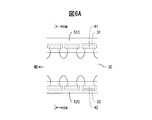
- the wing member continuous body 3C is cut in the transverse direction at predetermined intervals together with the first and second separator continuous bodies 51C and 52C.
- the wing member 3 having the adhesive portions 41 and 42 and the separators 51 and 52 is formed.
- the wing member 3 is separated from the wing member continuous body 3C.
- the wing member 3 is further conveyed while being held, for example, with a negative pressure by the anvil roll 72A.
- the peripheral speeds of the cutter roll 72C and the anvil roll 72A are made larger than the conveying speed of the wing member continuous body 3, and as a result, slip occurs between the cutter roll 72C and the anvil roll 72A and the wing member continuous body 3. Generated.
- the wing members 3 are conveyed at intervals in the conveyance direction MD.
- the wing member 3 conveyed by the anvil roll 72A is then stacked on the back sheet continuous body 2BC and released from the anvil roll 72A. Therefore, as shown in FIGS. 7A and 7B, the wing member 3 is joined to the back sheet continuous body 2BC by the adhesive from the adhesive applicator AA1.
- the first projecting portions 31 located on one side of the wing member continuous body 3C are connected to each other by the first separator continuous body 51C.
- the second projecting portions 32 positioned on the other side of the wing member continuous body 3C are connected to each other by the second separator continuous body 52C.
- the first separator 41 is provided in the first protruding portion 31, and the second separator 42 is provided in the second protruding portion 32. Yes. Therefore, in any case, the first and second projecting portions 31 and 32 are restrained from moving freely. Therefore, the formation of wrinkles and the like in the wing member continuous body 3C is suppressed.
- the back sheet continuous body 2BC and the wing member 3 are then sent to the suction roll R5 and the suction device 74.
- the suction roll R5 and the suction device 74 convey the back sheet continuous body 2BC and the wing member 3 with a negative pressure, for example.
- the back sheet continuous body 2BC and the wing member 3 are sent to the overlapping device 75.
- the adhesive 6 is intermittently applied to the first separator 51 by the adhesive applicator 73. Further, an adhesive is applied to the back surface continuous sheet 2BC and the wing member 3 at a predetermined position by an adhesive applicator AA2.
- the continuous surface sheet 2TC in which the absorbent cores 2A are arranged while being separated from each other in the transport direction MD is sent to the superposing device 75.
- the surface sheet continuous body 2TC is composed of a plurality of surface sheets 2T that are continuous with each other.
- the back sheet continuous body 2BC and the wing member 3 are superposed and joined to the top sheet continuous body 2TC.
- an absorbent article continuous body 1 ⁇ / b> C composed of a plurality of absorbent articles 1 continuous with each other is formed.
- the wing member 3 is overlaid on the absorbent core 2A.
- the absorbent article continuous body 1 ⁇ / b> C is sent to the folding device 76.
- the folding device 76 the protruding portions 31 and 32 of the wing member 3 are folded over the top sheet continuous body 2TC. Further, the first and second separators 51 and 52 are joined to each other by the adhesive 6.
- the absorbent article continuous body 1C is sent to the cutting device C3.
- the absorbent article continuum 1C is cut in the transverse direction at predetermined intervals. As a result, the absorbent article 1 is formed.
- the wing member 3 is joined to the back sheet continuous body 2BC in the anvil roll 72A.
- the wing member 3 is joined to the surface sheet continuous body 2TC in the anvil roll 72A.
- the first and second separator continuous bodies 51C and 52C are positioned on the cutter roll 71 side, and the wing member continuous body 3C is positioned on the anvil roll 72A side.
- the second separator continuums 51C and 52C and the wing member continuum 3C are sent. If it does in this way, the protrusion parts 31 and 32 will be directly hold
- the separator continuums 51C and 52C and the wing member continuum 3C are arranged such that the separator continuums 51C and 52C are located on the anvil roll 72A side and the wing member continuum 3C is located on the cutter roll 71 side. Will be sent.
- a step corresponding to the thickness of the wing member continuous body 3 ⁇ / b> C exists between the two protruding portions 31, 31 adjacent to each other in the transport direction MD and between the protruding portions 32, 32.
- the first and second adhesive portions 41 and 42 are formed on the first and second separators 51 and 52, and then the first and second protruding portions 31 and 32 are formed. Is transcribed. In another embodiment, the adhesive portions 41, 42 are formed directly on the protruding portions 31, 32.
- the recessed portions 3D and 3D are formed in the protruding portions 31 and 32, respectively.
- the protruding portions 31 and 32 are not formed with concave grooves. In this case, the projecting portions 31 and 32 forms a respective trapezoidal.
Landscapes
- Health & Medical Sciences (AREA)
- Epidemiology (AREA)
- Engineering & Computer Science (AREA)
- Biomedical Technology (AREA)
- Heart & Thoracic Surgery (AREA)
- Vascular Medicine (AREA)
- Life Sciences & Earth Sciences (AREA)
- Animal Behavior & Ethology (AREA)
- General Health & Medical Sciences (AREA)
- Public Health (AREA)
- Veterinary Medicine (AREA)
- Manufacturing & Machinery (AREA)
- Absorbent Articles And Supports Therefor (AREA)
Applications Claiming Priority (2)
| Application Number | Priority Date | Filing Date | Title |
|---|---|---|---|
| JP2011170157A JP5717581B2 (ja) | 2011-08-03 | 2011-08-03 | 吸収性物品の製造方法 |
| JP2011-170157 | 2011-08-03 |
Publications (1)
| Publication Number | Publication Date |
|---|---|
| WO2013018436A1 true WO2013018436A1 (ja) | 2013-02-07 |
Family
ID=47628976
Family Applications (1)
| Application Number | Title | Priority Date | Filing Date |
|---|---|---|---|
| PCT/JP2012/064682 WO2013018436A1 (ja) | 2011-08-03 | 2012-06-07 | 吸収性物品の製造方法 |
Country Status (3)
| Country | Link |
|---|---|
| JP (1) | JP5717581B2 (zh) |
| TW (1) | TW201325568A (zh) |
| WO (1) | WO2013018436A1 (zh) |
Cited By (1)
| Publication number | Priority date | Publication date | Assignee | Title |
|---|---|---|---|---|
| EP3364919A4 (en) * | 2015-10-23 | 2019-07-17 | Curt G. Joa, Inc. | FEMININE HYGIENE PRODUCTS AND APPARATUS AND METHODS FOR THE PRODUCTION OF DISPOSABLE PRODUCTS |
Families Citing this family (3)
| Publication number | Priority date | Publication date | Assignee | Title |
|---|---|---|---|---|
| JP6383723B2 (ja) * | 2013-06-25 | 2018-08-29 | 株式会社瑞光 | ウイング付き吸収性物品とその製造方法 |
| JP6422128B2 (ja) * | 2013-06-25 | 2018-11-14 | 株式会社瑞光 | 吸収性物品とその製造方法 |
| JP6165815B2 (ja) * | 2015-09-30 | 2017-07-19 | 国立大学法人 筑波大学 | 学習システム、学習方法、プログラム、記録媒体 |
Citations (5)
| Publication number | Priority date | Publication date | Assignee | Title |
|---|---|---|---|---|
| JPH0211140A (ja) * | 1988-03-31 | 1990-01-16 | Procter & Gamble Co:The | フラップと応力軽減手段を有する生理用ナプキン |
| JP2006158538A (ja) * | 2004-12-03 | 2006-06-22 | Kao Corp | 吸収性物品の製造方法 |
| JP2007105401A (ja) * | 2005-10-17 | 2007-04-26 | Kao Corp | 吸収性物品の製造方法 |
| JP2008289631A (ja) * | 2007-05-24 | 2008-12-04 | Kao Corp | 吸収性物品及びその製造方法 |
| JP2009136504A (ja) * | 2007-12-06 | 2009-06-25 | Uni Charm Corp | 吸収性物品およびその製造方法 |
-
2011
- 2011-08-03 JP JP2011170157A patent/JP5717581B2/ja active Active
-
2012
- 2012-06-07 WO PCT/JP2012/064682 patent/WO2013018436A1/ja active Application Filing
- 2012-08-01 TW TW101127781A patent/TW201325568A/zh unknown
Patent Citations (5)
| Publication number | Priority date | Publication date | Assignee | Title |
|---|---|---|---|---|
| JPH0211140A (ja) * | 1988-03-31 | 1990-01-16 | Procter & Gamble Co:The | フラップと応力軽減手段を有する生理用ナプキン |
| JP2006158538A (ja) * | 2004-12-03 | 2006-06-22 | Kao Corp | 吸収性物品の製造方法 |
| JP2007105401A (ja) * | 2005-10-17 | 2007-04-26 | Kao Corp | 吸収性物品の製造方法 |
| JP2008289631A (ja) * | 2007-05-24 | 2008-12-04 | Kao Corp | 吸収性物品及びその製造方法 |
| JP2009136504A (ja) * | 2007-12-06 | 2009-06-25 | Uni Charm Corp | 吸収性物品およびその製造方法 |
Cited By (2)
| Publication number | Priority date | Publication date | Assignee | Title |
|---|---|---|---|---|
| EP3364919A4 (en) * | 2015-10-23 | 2019-07-17 | Curt G. Joa, Inc. | FEMININE HYGIENE PRODUCTS AND APPARATUS AND METHODS FOR THE PRODUCTION OF DISPOSABLE PRODUCTS |
| US10729594B2 (en) | 2015-10-23 | 2020-08-04 | Curt G. Joa, Inc. | Feminine hygiene products and apparatus and methods for making disposable products |
Also Published As
| Publication number | Publication date |
|---|---|
| JP2013034491A (ja) | 2013-02-21 |
| JP5717581B2 (ja) | 2015-05-13 |
| TW201325568A (zh) | 2013-07-01 |
Similar Documents
| Publication | Publication Date | Title |
|---|---|---|
| JP4426163B2 (ja) | 吸収性物品の個別包装体およびその製造方法 | |
| JP5409897B2 (ja) | 弾性ウェブを提供する方法 | |
| JP5369285B2 (ja) | 使い捨て着用物品の製造方法 | |
| WO2012102071A1 (ja) | 吸収性物品の包装体及び吸収性物品の包装体の製造方法 | |
| JP5717581B2 (ja) | 吸収性物品の製造方法 | |
| JP2011092764A (ja) | おむつに使用するのに好適な閉鎖部品の製造方法 | |
| TW201143732A (en) | Packaging structure of absorbent article, and method for manufacturing the same | |
| JP6047323B2 (ja) | 使い捨ておむつ及びその製造方法 | |
| JP5297785B2 (ja) | 吸収性物品の製造方法 | |
| JP2008284059A (ja) | 吸収性物品の個装体の製造方法 | |
| US9737445B2 (en) | Method for producing a disposable incontinence diaper with contoured diaper side parts | |
| JP5508060B2 (ja) | 吸収性物品の製造方法 | |
| US20160030252A1 (en) | Slip-Cut Operation with Static Electric Holding Force and Ultrasonic Bonding Apparatus | |
| JP6220795B2 (ja) | 吸収性物品に係る連続シートの複合体の製造方法、及び製造装置 | |
| JP5750146B2 (ja) | 吸収性物品の包装体 | |
| JP6147326B1 (ja) | 吸収性物品の製造方法 | |
| JP6138903B1 (ja) | 吸収性物品の製造方法 | |
| PL204950B1 (pl) | Sposób i układ do wytwarzania podstawowego materiału wyjściowego do wytwarzania języczków łączących,materiał wyjściowy do wytwarzania języczków łączących, języczek łączący oraz wyrób chłonny | |
| JP4420864B2 (ja) | 吸収性物品の個装体の製造方法 | |
| JP2000245772A (ja) | 連続製造ラインにおいて吸収物品を製造する方法 | |
| JP2014128469A (ja) | 吸収性物品の個包装体及び吸収性物品の個包装体の製造方法 | |
| CN111743696B (zh) | 层叠体、吸收性物品、层叠体的制造方法以及层叠体的制造装置 | |
| JP6356980B2 (ja) | 吸収体の製造方法及び製造装置 | |
| WO2017115526A1 (ja) | 吸収性物品の製造方法 | |
| JP2008136642A (ja) | 縦長物品の製造方法 |
Legal Events
| Date | Code | Title | Description |
|---|---|---|---|
| 121 | Ep: the epo has been informed by wipo that ep was designated in this application |
Ref document number: 12820452 Country of ref document: EP Kind code of ref document: A1 |
|
| NENP | Non-entry into the national phase |
Ref country code: DE |
|
| 122 | Ep: pct application non-entry in european phase |
Ref document number: 12820452 Country of ref document: EP Kind code of ref document: A1 |