WO2013018340A1 - Dispositif de commande numérique - Google Patents
Dispositif de commande numérique Download PDFInfo
- Publication number
- WO2013018340A1 WO2013018340A1 PCT/JP2012/004802 JP2012004802W WO2013018340A1 WO 2013018340 A1 WO2013018340 A1 WO 2013018340A1 JP 2012004802 W JP2012004802 W JP 2012004802W WO 2013018340 A1 WO2013018340 A1 WO 2013018340A1
- Authority
- WO
- WIPO (PCT)
- Prior art keywords
- path
- point
- interpolation
- tip
- sky
- Prior art date
Links
Images


Classifications
-
- G—PHYSICS
- G05—CONTROLLING; REGULATING
- G05B—CONTROL OR REGULATING SYSTEMS IN GENERAL; FUNCTIONAL ELEMENTS OF SUCH SYSTEMS; MONITORING OR TESTING ARRANGEMENTS FOR SUCH SYSTEMS OR ELEMENTS
- G05B19/00—Programme-control systems
- G05B19/02—Programme-control systems electric
- G05B19/18—Numerical control [NC], i.e. automatically operating machines, in particular machine tools, e.g. in a manufacturing environment, so as to execute positioning, movement or co-ordinated operations by means of programme data in numerical form
- G05B19/414—Structure of the control system, e.g. common controller or multiprocessor systems, interface to servo, programmable interface controller
-
- G—PHYSICS
- G05—CONTROLLING; REGULATING
- G05B—CONTROL OR REGULATING SYSTEMS IN GENERAL; FUNCTIONAL ELEMENTS OF SUCH SYSTEMS; MONITORING OR TESTING ARRANGEMENTS FOR SUCH SYSTEMS OR ELEMENTS
- G05B19/00—Programme-control systems
- G05B19/02—Programme-control systems electric
- G05B19/18—Numerical control [NC], i.e. automatically operating machines, in particular machine tools, e.g. in a manufacturing environment, so as to execute positioning, movement or co-ordinated operations by means of programme data in numerical form
- G05B19/19—Numerical control [NC], i.e. automatically operating machines, in particular machine tools, e.g. in a manufacturing environment, so as to execute positioning, movement or co-ordinated operations by means of programme data in numerical form characterised by positioning or contouring control systems, e.g. to control position from one programmed point to another or to control movement along a programmed continuous path
-
- G—PHYSICS
- G05—CONTROLLING; REGULATING
- G05B—CONTROL OR REGULATING SYSTEMS IN GENERAL; FUNCTIONAL ELEMENTS OF SUCH SYSTEMS; MONITORING OR TESTING ARRANGEMENTS FOR SUCH SYSTEMS OR ELEMENTS
- G05B19/00—Programme-control systems
- G05B19/02—Programme-control systems electric
- G05B19/18—Numerical control [NC], i.e. automatically operating machines, in particular machine tools, e.g. in a manufacturing environment, so as to execute positioning, movement or co-ordinated operations by means of programme data in numerical form
- G05B19/41—Numerical control [NC], i.e. automatically operating machines, in particular machine tools, e.g. in a manufacturing environment, so as to execute positioning, movement or co-ordinated operations by means of programme data in numerical form characterised by interpolation, e.g. the computation of intermediate points between programmed end points to define the path to be followed and the rate of travel along that path
- G05B19/4103—Digital interpolation
-
- G—PHYSICS
- G05—CONTROLLING; REGULATING
- G05B—CONTROL OR REGULATING SYSTEMS IN GENERAL; FUNCTIONAL ELEMENTS OF SUCH SYSTEMS; MONITORING OR TESTING ARRANGEMENTS FOR SUCH SYSTEMS OR ELEMENTS
- G05B2219/00—Program-control systems
- G05B2219/30—Nc systems
- G05B2219/35—Nc in input of data, input till input file format
- G05B2219/35158—Calculation of contact point of tool on surface, curve
-
- G—PHYSICS
- G05—CONTROLLING; REGULATING
- G05B—CONTROL OR REGULATING SYSTEMS IN GENERAL; FUNCTIONAL ELEMENTS OF SUCH SYSTEMS; MONITORING OR TESTING ARRANGEMENTS FOR SUCH SYSTEMS OR ELEMENTS
- G05B2219/00—Program-control systems
- G05B2219/30—Nc systems
- G05B2219/39—Robotics, robotics to robotics hand
- G05B2219/39177—Compensation position working point as function of inclination tool, hand
-
- G—PHYSICS
- G05—CONTROLLING; REGULATING
- G05B—CONTROL OR REGULATING SYSTEMS IN GENERAL; FUNCTIONAL ELEMENTS OF SUCH SYSTEMS; MONITORING OR TESTING ARRANGEMENTS FOR SUCH SYSTEMS OR ELEMENTS
- G05B2219/00—Program-control systems
- G05B2219/30—Nc systems
- G05B2219/49—Nc machine tool, till multiple
- G05B2219/49344—Surface, 5-axis surface machining
-
- G—PHYSICS
- G05—CONTROLLING; REGULATING
- G05B—CONTROL OR REGULATING SYSTEMS IN GENERAL; FUNCTIONAL ELEMENTS OF SUCH SYSTEMS; MONITORING OR TESTING ARRANGEMENTS FOR SUCH SYSTEMS OR ELEMENTS
- G05B2219/00—Program-control systems
- G05B2219/30—Nc systems
- G05B2219/50—Machine tool, machine tool null till machine tool work handling
- G05B2219/50353—Tool, probe inclination, orientation to surface, posture, attitude
Definitions
- the present invention relates to a numerical control device.
- NC program machining program
- Conventional machine tools include a swing device that swings a tool about an axis parallel to a specific plane on a table that supports a workpiece, and a tool and swing about an axis perpendicular to the specific plane.
- a rotation device for rotating the device relative to the table, a transfer device for transferring the tool in the X-axis direction on the specific plane, and a tool in the Y-axis direction orthogonal to the X-axis on the specific plane.
- a 5-axis processing machine including a transfer device for transferring and a transfer device for transferring a tool in the Z-axis direction perpendicular to both the X-axis and the Y-axis is known.
- a numerical control device for performing numerical control of a 5-axis machine is shown.
- a machining point curve obtained by smoothly interpolating the locus of a machining point at the tip of a tool, and a locus of a reference tool length position separated from the machining point by a fixed distance from the machining base end side. Is obtained by smoothly interpolating the tool, and the turning point of the tool is adjusted so that the machining point at the tip of the tool passes on the machining point curve and the reference tool length position passes on the reference tool length position curve.
- the workpiece is smoothly machined by controlling the swing of the tool by the rotation and swing device and the transfer of the tool by the corresponding transfer device in the X-axis, Y-axis and Z-axis directions.
- the tool axis vector (x, y, z) specified by the machining program slightly changes from (0.0001, 0, 1) to (0, 0.0001, 1). Even so, the direction of the projection tool axis vector changes by 90 degrees. In this case, since the rotating device rotates the tool and the swinging device by 90 degrees, the tool and the swinging device are suddenly rotated. Due to such sudden rotation, the actual machining point position by the tool is deviated from the machining point position specified by the machining program, and the machining accuracy of the workpiece is reduced. Or given to machine tools.
- the object of the present invention is to prevent the tool and the table from rotating relatively suddenly even when the machining program includes a part for instructing the movement of the object to be transferred such that the direction of the projected tool axis vector changes suddenly. In other words, it is possible to suppress a decrease in machining accuracy of the workpiece and a mechanical shock.
- a numerical control device includes a plurality of transfer devices that move a workpiece or a tool that processes the workpiece along a plurality of transfer axes in order to process the workpiece with the workpiece as a transfer object,
- a table that supports the workpiece, and the plurality of transfer devices includes a swing device that swings the tool in a swing transfer shaft direction around a first shaft extending in a specific direction, and the first shaft.
- a machine tool including a pivoting device for relatively pivoting the swinging device and the tool and the table in a pivotal transfer axis direction about a second axis extending in a direction perpendicular to the axis
- a storage unit that stores a machining program for instructing machining of the workpiece, and reads the machining program stored in the storage unit, and is based on the read machining program.
- the workpiece is determined by the position coordinates of the tip of the tool in a reference coordinate system including a specific plane that is fixed on the table and perpendicular to the second axis, and a parameter that is an integrated length of the trajectory of the movement of the tool.
- a projected tool axis vector obtained by projecting a tool axis vector on the upper path toward the upper point onto the specific plane is obtained over the entire section of the end path and the upper path, and the end path and the upper path are obtained.
- a position adjustment position that is a position where a change rate of the direction of the projection tool axis vector with respect to the increment of the parametric variable exceeds a certain change rate in the path is specified, and a specific section extending before and after the specified position adjustment position is defined.
- Posture adjustment that is set as a posture adjustment section and obtains posture adjustment information for adjusting the posture of the tool in the posture adjustment section in a direction in which the change in the direction of the projected tool axis vector in the set posture adjustment section becomes gentle.
- An information deriving unit an acceleration / deceleration condition including an allowable acceleration of the transfer of the transfer object for each transfer axis when the transfer object is moved, the tip path and the sky path derived by the path deriving unit Based on the posture adjustment information derived by the posture adjustment information deriving unit, a parameter representing a change in the parameter with respect to the passage of a reference time
- a parametric time function deriving unit for obtaining a time function, the leading path and the sky path obtained by the path deriving unit, the number of parametric time periods obtained by the parametric variable time function deriving unit, and the posture adjustment information
- the position coordinates of the tip point and the tool axis vector at each time point for each unit time of the reference time are obtained, and the tip at each obtained time point In the direction of each transfer axis for moving the transfer object so that the tool axis vector of the tool matches the tool axis vector at each point of time when the tip point of the tool passes through the position coordinates
- a transfer command for determining the transfer amount per unit time of the object to be transferred, and using the determined transfer amount per unit time in the direction of each transfer axis as a transfer command for each transfer axis direction The transfer command for the transfer axis direction corresponding to the transfer device among the transfer commands for the transfer axis directions obtained by the transfer command deriving unit is output to the output unit and the transfer devices. And a controller for transferring the object to be transferred to each of the transfer devices according to the transfer command output to each of the transfer devices, wherein the transfer command deriving unit is obtained by the parameter time function deriving unit.
- the parametric variable corresponding to each time point is obtained based on the parametric time function, and among the parametric variables of the obtained time points, for the parametric variable in the posture adjustment section, the tip corresponding to the parametric variable is obtained.
- the position coordinates of the tip point on the path and the position coordinates of the sky point on the sky path are obtained, and the position coordinates of the sky point thus obtained are determined in the direction of the projection tool axis vector.
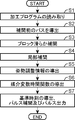
- FIG. 1 is a schematic perspective view of a machine tool to which a numerical control device according to an embodiment of the present invention is applied. It is a functional block diagram of the numerical control apparatus by one Embodiment of this invention. It is a flowchart which shows the numerical control process by the numerical control apparatus by one Embodiment of this invention. It is a flowchart which shows the detailed process of the local interpolation among the numerical control processes shown in FIG. It is a flowchart which shows the detailed process of derivation
- FIG. 7 is a flowchart showing a detailed process of deriving a tool position on a path in FIG. 6 and position coordinates newp [] of each transfer axis. It is a figure for demonstrating the calculation method of the distribution area width in one Embodiment of this invention. It is a schematic diagram which shows the corner part used as the object of local interpolation among front-end
- the section where the trajectory indicated by the projection tip path and the trajectory indicated by the projection sky path are separated from each other and the change rate of the direction of the projection tool axis vector is equal to or greater than a predetermined change rate set as a parameter is the projection tip path and the projection sky path. It is a figure which shows the example which exists in. It is a figure which shows the example which a projection front-end path
- FIG. 10 is a diagram illustrating an example in which a projected front path and a projected sky path intersect and the control line is nearly parallel to the tangential direction of the projected front path at the start point and the end point of the posture adjustment section.
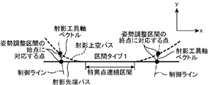
- FIG. 10 is a diagram illustrating an example in which a projected tip path and a projected sky path touch at one point and a control line is nearly parallel to the tangential direction of the projected tip path at the start point and the end point of the posture adjustment section. It is a figure which shows the example which a singular point continuous area exists in an attitude
- a singular point continuous section exists in the posture adjustment section, and the control line is not nearly parallel to the traveling direction of the projection tip path at the start point of the posture adjustment section, and the control line advances in the projection tip path at the end point of the posture adjustment section.
- This machine tool is a gate-type machine tool, and works the workpiece 100 with the tool 106 while moving the tool 106 on the workpiece 100 as a workpiece set on the table 101a.
- the machine tool includes a table 101a, a bed 101b, a table transfer device 102 (see FIG. 2), two columns 104, a cross rail 105, a tool 106, a spindle head 108, , A swing device 110, a rotation device 112, a vertical transfer device 114, a horizontal transfer device 116, and a control box 120 are provided.
- the table transfer device 102, the swing device 110, the rotation device 112, the vertical transfer device 114, and the horizontal transfer device 116 are used for processing the workpiece 100 using the workpiece 100 or the tool 106 as a transfer target. It moves along a plurality of transfer axes, and each is included in the concept of the transfer device of the present invention.
- the table 101a supports the workpiece 100 set thereon from below.
- the bed 101b is installed at a predetermined installation location, and supports the table 101a from below so that the table 101a can move in the X-axis direction extending in a specific direction in a horizontal plane.
- the table transfer device 102 is provided in the bed 101b and transfers the table 101a along the X axis, thereby transferring the workpiece 100 set on the table 101a along the X axis.
- the X axis is included in the concept of the transfer axis of the present invention.
- the table transfer device 102 has a servo motor (not shown) as a drive source, and transfers the table 101a by the power of the motor.
- the two columns 104 are separately provided on both sides of the table 101a and the bed 101b in a direction (width direction of the table 101a) orthogonal to the moving direction (X-axis direction) of the table 101a.
- the cross rail 105 is disposed above the table 101a and is stretched over the two columns 104 so as to extend in the width direction of the table 101a (the direction perpendicular to the X axis in the horizontal direction).
- the tool 106 is for cutting the workpiece 100 and is held by the spindle head 108.
- the spindle head 108 rotates the held tool 106 around its axis.
- the workpiece 100 is machined when the tool 106 rotated by the spindle head 108 contacts the workpiece 100.
- the swinging device 110 swings the tool 106 in the A-axis direction around an axis extending in the horizontal direction parallel to the upper surface of the table 101a.
- the axis extending in the horizontal direction is included in the concept of the first axis of the present invention, and the A axis is included in the concepts of the transfer shaft and the swinging transfer shaft of the present invention.
- the rocking device 110 includes a rocking support member 110a and a rocking support member transfer unit 110b (see FIG. 2).
- the swing support body 110a is supported by the rotation device 112 so as to be swingable about the axis extending in the horizontal direction.
- the swing support body 110a has a posture in which the spindle head 108 is orthogonal to the axis that is the center of swing of the swing support body 110a with the rotation axis of the tool 106 held by the spindle head 108.
- the swing support body transfer part 110b swings the spindle head 108 and the tool 106 in the A axis direction together with the swing support body 110a by swinging the swing support body 110a in the A axis direction.
- the swing support body transfer unit 110b has a servo motor (not shown) as a drive source, and swings the swing support body 110a with the power of the motor.
- the rotating device 112 moves the tool 106 and the swinging device 110 relative to the table 101a in the C-axis direction centering on an axis extending in a direction perpendicular to the axis that is the swing center of the tool 106 by the swinging device 110. And rotate it relatively.
- the axis extending in a direction perpendicular to the axis serving as the center of oscillation of the tool 106 is included in the concept of the second axis of the present invention, and the C axis is the transfer axis and the rotation transfer axis of the present invention. Included in the concept.
- the rotation device 112 includes a rotation support body 112a and a rotation support body transfer section 112b (see FIG. 2).
- the rotation support body 112a is supported by the vertical transfer device 114 so as to be rotatable about an axis perpendicular to the axis serving as the center of oscillation of the tool 106. Moreover, the rotation support body 112a supports the rocking device 110 in the lower part thereof.
- the rotation support body transfer unit 112b rotates the rotation support body 112a in the C-axis direction, thereby rotating the rotation support body 112a together with the swinging device 110, the spindle head 108, and the rotation support body 112a.
- the tool 106 is rotated in the C-axis direction.
- the rotation support body transfer part 112b has a servo motor (not shown) as a drive source, and rotates the rotation support body 112a by the power of the motor.
- the vertical transfer device 114 is for transferring the tool 106 along the Z axis orthogonal to the X axis and extending in the vertical direction.
- the Z axis is included in the concept of the transfer axis of the present invention.
- the vertical transfer device 114 includes a ram 114a and a ram transfer unit 114b (see FIG. 2).
- the ram 114a is disposed above the table 101a and supported by the horizontal transfer device 116 so as to be movable in the vertical direction (vertical direction) along the Z axis. Further, the ram 114 a supports the rotating device 112 at a position above the table 101 a and below the cross rail 105 by the lower portion thereof.
- the ram transfer unit 114b transfers the ram 114a in the Z-axis direction, thereby transferring the rotation device 112, the swing device 110, the spindle head 108, and the tool 106 supported by the ram 114a together with the ram 114a in the Z-axis direction. To do.
- the ram transfer unit 114b has a servo motor (not shown) as a drive source, and transfers the ram 114a by the power of the motor.
- the horizontal transfer device 116 is for transferring the tool 106 along the Y axis orthogonal to both the X axis and the Z axis.
- the Y axis is included in the concept of the transfer axis of the present invention.
- the horizontal transfer device 116 includes a saddle 116a and a saddle transfer unit 116b (see FIG. 2).
- the saddle 116a is supported by the cross rail 105 so as to be movable along the Y axis above the table 101a. That is, the saddle 116a is movable above the table 101a so as to cross the table 101a in the width direction.
- the saddle 116a supports the vertical transfer device 114 at the lower part thereof.
- the saddle transfer unit 116b transfers the saddle 116a in the Y-axis direction, thereby the vertical transfer device 114, the rotation device 112, the swing device 110, the spindle head 108, and the tool 106 supported by the saddle 116a together with the saddle 116a. Transfer in the Y-axis direction.
- the saddle transfer section 116b has a servo motor (not shown) as a drive source, and transfers the saddle 116a by the power of the motor.
- the control box 120 controls the table transfer device 102, the swing device 110, the rotation device 112, the vertical transfer device 114 and the horizontal transfer device 116, the spindle head 108, and other parts of the machine tool. It has the function of.
- the numerical control device 2 according to the present embodiment is incorporated in the control box 120.
- the numerical control device 2 outputs a command pulse (transfer command) for each specific period to the table transfer device 102 and the transfer units 110b, 112b, 114b, and 116b, thereby transferring the transfer devices 102, 110, and 112. , 114 and 116 are numerically controlled.
- the numerical control device 2 includes a storage unit 4, a memory 5, and an arithmetic processing unit 6.
- the storage unit 4 stores workpiece installation information, information on a specific plane described later, a machining program (NC program), a distance parameter that is a constant value, and a transfer axis coordinate calculation function.
- NC program machining program
- the workpiece installation information is information representing the position and orientation of the workpiece 100 on the table 101a.
- the workpiece placement information represents a relative position and inclination of the workpiece coordinate system as a program coordinate system fixed to the workpiece 100 placed on the table 101a with respect to the reference coordinate system.
- the reference coordinate system is a coordinate system that is fixed (set) on the table 101a and serves as a reference for transferring the transfer object.
- the reference coordinate system includes an x-axis parallel to the transfer direction (X-axis direction) of the table 101a in the horizontal plane, a y-axis orthogonal to the x-axis in the horizontal plane and parallel to the Y-axis, and the x-axis and y-axis.
- the reference coordinate system is a specific plane perpendicular to an axis extending in a direction perpendicular to the axis serving as the center of oscillation of the tool 106 (axis serving as the center in the C-axis direction, which is the rotation direction of the tool 106).
- xy plane The work coordinate system includes an x ′ axis, a y ′ axis, and a z ′ axis that are orthogonal to each other.
- the work installation information includes information on a relative position of the work coordinate system in the reference coordinate system (xyz coordinate system) (a parallel shift amount of the work coordinate system with respect to the reference coordinate system) and inclination of the work coordinate system with respect to the reference coordinate system.
- the workpiece setting information is represented by a relative relationship between the workpiece coordinate system (x′y′z ′ coordinate system) and the reference coordinate system (xyz coordinate system), and (x0, y0, z0, ⁇ ). , ⁇ , ⁇ ).
- (x0, y0, z0) is the coordinate value of the origin of the workpiece coordinate system on the reference coordinate system
- ( ⁇ , ⁇ , ⁇ ) represents the posture of rotation of the workpiece coordinate system with respect to the reference coordinate system. Euler angle.
- This workpiece placement information is input using an input device (not shown) when the workpiece 100 is placed on the table 101 a and stored in the storage unit 4.
- the machining program is a machining command for instructing machining of the workpiece 100.
- the machining program includes a tool path in the workpiece coordinate system.
- the tool path represents a trajectory of the movement of the tool 106 according to the passage of the reference time when machining the workpiece 100.
- Information and a feed speed command indicating the speed along the movement locus of the tool 106 are included.
- the tool movement trajectory indicated by the tool path forms a ruled curved surface that connects adjacent command points included in the tool path and satisfies the inclination of the tool axis vector at each command point.
- the distance parameter is a control parameter representing a separation distance from the tip point of the tool 106 to a corresponding sky point (described later).
- the transfer axis coordinate calculation function includes a position coordinate of a tip point corresponding to an arbitrary parameter in a reference coordinate system, a tool axis vector corresponding to the parameter and starting from the tip point, and each transfer axis coordinate. It is a function that defines the correlation.
- each transfer device 102, 110, 112, 114, and 116 are functions for calculating the position coordinates at which the transfer object is arranged in the corresponding transfer axis direction.
- the storage unit 4 stores acceleration / deceleration conditions and other set values (parameters) when moving the object to be transferred when the workpiece 100 is processed.
- the acceleration / deceleration conditions include, for example, permissible speed, permissible acceleration and permissible jerk in each transport axis direction when each transport device 102, 110, 112, 114, 116 transports a transport target, and a tool for the workpiece 100.
- 106 the allowable speed, allowable acceleration and allowable jerk of the movement including the posture change, the upper limit value of the parameter variable which is the integrated value of the movement amount including the posture change of the tool 106, the upper limit value of the acceleration of the parameter, Contains the upper limit of variable jerk.
- the parameter is an integrated value of the movement amount including the posture change of the tool 106.
- the parameter is an integrated value obtained by adding the amount of change in the posture (tilt) of the tool 106 to the amount of movement of the tip point of the tool 106.
- the parameter of the tip point of the tool 106 is moved. It is an average value of the amount and the amount of movement of the sky point that is separated from the distal end point by the distance parameter along the axial center of the tool 106 to the proximal end side of the tool 106.
- the memory 5 temporarily stores various information, and stores, for example, a post-local interpolation tip path, posture adjustment information, and other information described later.
- the arithmetic processing unit 6 performs various types of arithmetic processing. As functional blocks, the path deriving unit 12, the attitude adjustment information deriving unit 16, the parameter variable time function deriving unit 18, the transfer command deriving unit 20, and the control Part 22.
- the path deriving unit 12 reads the machining program stored in the storage unit 4, and obtains the tip path and the sky path of the tool 106 based on the read machining program.
- the tip path represents the movement of the tip point of the tool 106 during machining of the workpiece 100 by a function of the position coordinate of the tip point in the reference coordinate system and a parametric variable.
- the movement of the sky point of the tool 106 is represented by a function of the position coordinate of the sky point in the reference coordinate system and a parameter.
- the path deriving unit 12 includes a pre-interpolation path deriving unit 13 and a path interpolation unit 14 as functional blocks.
- the pre-interpolation path deriving unit 13 calculates a pre-interpolation tip path and a pre-interpolation sky path from a tool path included in the machining program. Specifically, the pre-interpolation path deriving unit 13 reads a tool path (work coordinate system tool path) in the work coordinate system included in the machining program from the machining program read from the storage unit 4. Then, the pre-interpolation path deriving unit 13 converts the read work coordinate system tool path into a tool path on the reference coordinate system (reference coordinate system tool path) based on the work installation information stored in the storage unit 4. The tip path before interpolation and the sky path before interpolation are calculated from the converted reference coordinate system tool path. The pre-interpolation path deriving unit 13 causes the storage unit 4 to store the calculated pre-interpolation tip path and pre-interpolation sky path.
- the path interpolation unit 14 interpolates the pre-interpolation tip path and the pre-interpolation upper path calculated by the pre-interpolation path deriving unit 13, respectively.
- the term “interpolation” as used herein refers to correcting each of the paths so that the trajectory indicated by the pre-interpolation leading path and the pre-interpolation upper path becomes a smooth curve.
- the path interpolation unit 14 includes a smooth interpolation unit 14a and a path local filter 14b as functional blocks.
- the smooth interpolation unit 14a interpolates the pre-interpolation front end path calculated by the pre-interpolation path deriving unit 13 so that the movement of the front end point represented by the path is smooth and the pre-interpolation calculated by the pre-interpolation path deriving unit 13 Smooth interpolation is performed to interpolate the sky path so that the motion of the sky point represented by the path is smooth.
- the smooth interpolation unit 14a performs so-called block smooth interpolation on a portion of the both paths calculated by the pre-interpolation path deriving unit 13 that can be analytically interpolated so as to be a smooth curve passing through the command point. To implement.
- the smooth interpolation unit 14a uses the section between adjacent command points in the pre-interpolation front-end path as a command block so that the command block and the adjacent command block are smoothly connected at the command points at their boundaries. Interpolate the tip path before interpolation. Specifically, the smooth interpolation unit 14a continuously changes the primary differential value and the secondary differential value due to the parameter of the front-end front path before and after the command point at the boundary between adjacent command blocks, and passes through the command point. The tip path is interpolated so that the path becomes like this.
- the smooth interpolation unit 14a does not perform interpolation such as a straight line-arc contact point or a circle-circle contact point. There are also places to leave.
- the smooth interpolation unit 14a does not interpolate the above-mentioned points in the tip path before interpolation, leaves the original path as it is, passes through the command point as described above, and performs first-order differentiation using a parameter before and after the command point. Smooth interpolation is performed on the part that can be interpolated into a curve in which the value and the second derivative value continuously change. In addition, the smooth interpolation unit 14a performs smooth interpolation similar to that for the pre-interpolation tip path on the pre-interpolation sky path.
- the path local filter 14b is a portion where the first derivative or the second derivative is discontinuously changed, and the speed indicated by the portion is not interpolated by the smooth interpolation unit 14a among the pre-interpolation leading-end path and the pre-interpolation upper-pass.
- the local interpolation is performed for non-zero locations.
- the path local filter 14b has a continuous first-order differential value based on a parametric variable and a variable based on a parametric variable, except for a point where the speed is zero (a point where processing is desired to stop once) in the pre-interpolation front-end path.
- a command point at which the secondary differential value is discontinuous and a command point at which the primary differential value by the parametric variable is discontinuous are set as interpolation target points.
- the path local filter 14b has an interpolation section width, which will be described later, before and after the interpolation target point in the pre-interpolation tip path, and an interpolation section in which the interpolation target point is located at the center of the interpolation section width. Local interpolation is performed so that differential values that are discontinuous at the interpolation target point are continuous.
- the path local filter 14b performs the following local interpolation processing on the pre-interpolation tip path.
- Examples of the location where the local interpolation is performed by the path local filter 14b include a corner portion as shown in FIG. 9 and an abnormal data portion as shown in FIG.
- the command point (t [3] in FIG. 9) located at the apex of the corner part and at each command point (t [2] to t [6] in FIG. 10) located at each vertex of the abnormal data part it depends on the parameter.
- the primary differential value and the secondary differential value are discontinuous, and these command points are interpolation target points.
- the path local filter 14b includes a plurality of interpolation target points in the front-end front path before interpolation, and when the interpolation sections of adjacent interpolation target points overlap (in the case of FIG. 10), these overlap.
- the interpolation section one interpolation section is defined from the start point of the interpolation section located closest to the start point of the pre-interpolation tip path to the end point of the interpolation section located closest to the end point of the pre-interpolation tip path. Interpolate the tip path locally.
- the front end path after all the interpolation sections are locally interpolated by the path local filter 14b is referred to as a post-local interpolation front end path.
- the path local filter 14b is such that the front end path after the local interpolation is continuously before and after the start point and before and after the end point of each interpolation section (in the case where adjacent interpolation sections overlap each other).
- the interpolation section is locally interpolated so as to be connected.
- the path local filter 14b performs the same local interpolation processing as the pre-interpolation tip path on the pre-interpolation sky path.
- the sky path after all the interpolation sections are locally interpolated by the path local filter 14b is referred to as a post-local interpolation sky path.
- the post-local interpolation front end path corresponds to the front end path obtained by the path deriving unit 12 based on the machining program
- the post-local interpolation upper path corresponds to the upper path obtained by the path deriving unit 12 based on the machining program.
- the path local filter 14b includes a local interpolation unit 14c and an error correction unit 14d as functional blocks (see FIG. 2).
- the local interpolation unit 14c obtains a post-interpolation function of each interpolation block by performing interpolation processing on each of the plurality of interpolation blocks related to the adjustment section obtained by expanding the interpolation section of the front-end path back and forth, and calculates the post-interpolation function.
- the post-interpolation integration function is obtained, and by extracting the interval corresponding to the interpolation interval from the obtained post-interpolation integration function, the change in the derivative that is discontinuous at the interpolation target point in the interpolation interval is continuous.
- a tip interpolation path with an error interpolated so as to change is obtained.
- the local interpolation unit 14c performs the same process on the sky interpolation path with an error that is interpolated so that the change in the derivative that is discontinuous at the interpolation target point in the interpolation section becomes a continuous change.
- the error correction unit 14d matches the value corresponding to the start point of the interpolation section of the tip interpolation path with error obtained by the local interpolation unit 14c with the value of the start point of the interpolation section of the tip path that is not locally interpolated, and Correct the tip interpolation path with error so that the value corresponding to the end point of the interpolation section of the tip interpolation path with error matches the end point value of the interpolation section of the tip path that is not locally interpolated, and the corrected tip interpolation path Is replaced with the interpolation section of the tip path to derive the tip path after the local interpolation. Further, the error correction unit 14d corrects the sky interpolation path with error by the same process, and derives the sky path after the local interpolation by replacing the corrected sky interpolation path with the interpolation section of the sky path.
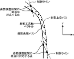
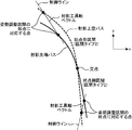
- the posture adjustment information deriving unit 16 identifies a posture adjustment point where the direction of the tool axis vector from the tip point toward the sky point corresponding to the tip point changes abruptly among the tip path after local interpolation and the sky path after local interpolation, A posture adjustment section, which is a parameter variable section before and after the specified posture adjustment position, is extracted, and the posture of the tool 106 in the posture adjustment section is adjusted in a direction in which the change in the direction of the tool axis vector becomes gentle in the posture adjustment section. Posture adjustment information for adjustment is obtained.
- the posture adjustment information deriving unit 16 uses the tool axis as the posture adjustment point where the posture of the tool 106 is to be adjusted with respect to the traveling direction of the tip path after local interpolation among the tip path after local interpolation and the sky path after local interpolation.
- the mediation of the direction of the projected tool axis vector obtained by projecting the tool axis vector onto the specific plane among the part where the angle formed by the vector increases or decreases during the short movement distance of the tool 106 and the tip path after local interpolation and the sky path after local interpolation A location where the rate of change relative to the increment of the variable exceeds a certain rate of change set as a parameter is specified.
- the locus indicated by the projected tip path obtained by projecting the tip after the local interpolation onto the specific plane and the local interpolation The trajectory indicated by the projected sky path obtained by projecting the rear sky path onto the specific plane is separated from each other, and the angle between the projection tool axis vector and the reference direction (y-axis direction in the present embodiment) in the specific plane is Sections where the rate of change relative to the increase of the parametric variable exceeds a certain rate of change, or the point indicated by the tip after the local interpolation when viewed from the direction perpendicular to the specific plane and the point indicated by the path after the local interpolation overlap ( A section including an intersection and a contact point, a section including a point where points where the two trajectories overlap are included, and the like.
- the posture adjustment information deriving unit 16 uses the tool 106 for a posture adjustment point including an intersection where a trajectory indicated by the tip path after local interpolation and a trajectory indicated by the sky path after local interpolation intersect when viewed from the direction perpendicular to the specific plane.
- the condition that the top point of the tool 106 is located at a point on the post-local interpolation upper path corresponding to the intersection point in the parametric variable located at the point on the post-local interpolation tip path corresponding to the intersection point is satisfied. Find posture adjustment information.
- the posture adjustment information deriving unit 16 tracks the change in the posture of the tool 106 represented by the post-local interpolation tip path and the post-local interpolation top pass, and corresponds to the tip point on the post-local interpolation tip path. Calculate the angle of the C-axis coordinate at the location where the correspondence of the sky point on the sky path after local interpolation should be adjusted and / or the direction of the projection tool axis vector (at the singular point where the length of the projection tool axis vector is 0) The position adjustment information is found, and the posture adjustment information including the posture adjustment section information and the tip sky corresponding adjustment function S (s) and / or the direction specifying function C (s) is obtained, and the posture adjustment information is obtained. Is registered in the memory 5.
- the tip sky corresponding adjustment function S (s) is a function used to adjust the sky point on the post-local interpolation upper path corresponding to the tip point on the post-local interpolation tip path.
- This tip / upper correspondence adjustment function S (s) is included in the concept of the tip / top correspondence relationship of the present invention.
- the tip over sky corresponding adjustment function S (s) is after the local interpolation from the point corresponding to the starting point of the posture adjustment section to the arbitrary point corresponding to any parameter in the posture adjustment section in the tip path after the local interpolation.
- Predetermined point on the post-local interpolation sky path that corresponds to the arbitrary point on the post-local interpolation tip path from the point corresponding to the starting point of the posture adjustment section of the travel distance along the tip path and the top path after local interpolation
- the direction specifying function C (s) is a function used to adjust the direction of the projection tool axis vector (when the singular point where the length of the projection tool axis vector is 0, the reference for calculating the angle of the C axis coordinate). It is.
- the direction specifying function C (s) has an angle between a control line, which is a straight line passing through a point on the projection tip path and a point on the projection sky path corresponding to the point, and the reference direction on the specific plane.
- the relationship between the direction specifying angle, which is the angle between the control line and the reference direction, and the parameter in the posture adjustment section is defined so as to change at a uniform rate from the start point to the end point of the posture adjustment section.
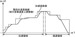
- the parametric variable time function deriving unit 18 is derived by the acceleration / deceleration conditions stored in the storage unit 4, the post-local interpolation tip path and the post-local interpolation sky path, and the attitude adjustment information deriving unit 16 and registered in the memory 5. Based on the obtained posture adjustment information, a parameter time function (parameter variable velocity curve) representing a change of the parameter with respect to the passage of the reference time is obtained. Specifically, the parametric variable time function deriving unit 18 uses the transfer axis coordinate calculation function stored in the storage unit 4 to perform each of the interpolated tip path, the post-local interpolation sky path, and the posture adjustment information.
- Transfer axis paths (X-axis path, Y-axis path, Z-axis path, A-axis path, and C-axis path) are calculated. Then, the parametric variable time function deriving unit 18 obtains the approximate value of the first derivative by the parameter of each transfer axis path and the approximate value of the second derivative by the parameter, and calculates the first derivative in each block between the command points. From the approximate value and the second-order differential approximate value, the parameter s of each block is set so as to satisfy the condition that the acceleration in the transfer axis direction of the object to be transferred does not exceed the allowable acceleration in the transfer axis direction included in the acceleration / deceleration conditions.
- a parametric time function is derived that indicates the maximum acceleration that can be transferred along the rear sky path.
- the transfer command deriving unit 20 includes a parameter time function derived by the parameter time function deriving unit 18, a tip path after local interpolation, an empty path after local interpolation, posture adjustment information, and a transfer axis coordinate calculation function. Based on this, the transfer amount for each reference unit time (specific cycle) of the transfer object in the direction of each transfer axis is obtained, and the determined transfer amount for each reference unit time of the transfer object in the direction of each transfer axis is commanded. And
- the reference unit time is a unit time of the reference time.
- the command pulse is included in the concept of the transfer command of the present invention.
- the transfer command deriving unit 20 derives a parameter corresponding to each time point for each reference unit time of the reference time based on the parameter time function derived by the parameter time function deriving unit 18.
- the transfer command deriving unit 20 determines the position coordinate of the tip point on the post-local interpolation tip path corresponding to the parameter, for the parameter in the posture adjustment section among the derived parameter at each time point, A tool axis vector heading toward the sky point on the sky path after local interpolation, in which the relative positional relationship from the tip point to the tip point is adjusted in a direction in which the change in the direction of the projected tool axis vector becomes gentle based on the posture adjustment information; Ask for.
- the transfer command deriving unit 20 determines the position coordinates of the tip point on the post-local interpolation tip path corresponding to the parameter, for the parameter outside the posture adjustment section among the derived parameter at each time point, The tool axis vector from the tip point to the sky point on the sky path after local interpolation corresponding to the parameter is obtained. Further, the transfer command deriving unit 20 passes the position coordinates of the tip point obtained for the parameter at each time point through the tip point of the tool 106 and sets the tool 106 to the tool axis vector obtained for the parameter at each time point. A transfer amount per reference unit time of the transfer object in the direction of each transfer axis for moving the transfer object so that the tool axis vectors match is obtained.
- the transfer command deriving unit 20 corresponds to the parameter at each time point using the transfer axis coordinate calculation function from the position coordinates of the tip point and the tool axis vector obtained for the parameter at each time point as described above.
- the position coordinates on each transfer axis are obtained, the amount of change per position unit time of the position coordinates on each transfer axis is obtained from the position coordinates on each transfer axis at each obtained time point, and the change amount is handled.
- the transfer amount per reference unit time of the object to be transferred in the transfer axis direction sets the transfer amount per reference unit time of the object to be transferred in each transfer axis direction thus obtained as a command pulse for each reference unit time (for each specific period).
- the control unit 22 controls the operation of each transfer device 102, 110, 112, 114, 116.
- This control unit 22 causes each transfer device 102, 110, 112, 114, 116 to transfer the transfer object in accordance with the command pulse for each specific period obtained by the transfer command deriving unit 20.
- the control unit 22 includes the servo motor of the table transfer device 102 and the transfer units 110b, 112b, and 114b among the command pulses for each specific period in each transfer axis direction obtained by the transfer command deriving unit 20.
- 116b a command pulse indicating a transfer amount in the transfer axis direction corresponding to each servo motor is output to each servo motor.
- the object to be transferred is transferred in accordance with the command pulse output to each transfer device 102, 110, 112, 114, 116.
- the path deriving unit 12 reads the machining program (NC program) stored in the storage unit 4 (step S1 in FIG. 3), and the pre-interpolation path deriving unit 13 reads the pre-interpolation tip path and the pre-interpolation sky from the machining program.
- a path is obtained (step S2).
- the pre-interpolation path deriving unit 13 reads a work coordinate system tool path included in the machining program, and uses the work coordinate system tool path as a reference coordinate system based on the work installation information stored in the storage unit 4. Conversion to a tool path is performed, and a tip path before interpolation and a sky path before interpolation are obtained from the converted reference coordinate system tool path.
- the pre-interpolation path deriving unit 13 derives a function representing the position coordinates of the tip point p (s) in the reference coordinate system with respect to an arbitrary parameter s as a pre-interpolation tip path, and the arbitrary parameter s A function representing a position coordinate in the reference coordinate system of the sky point P (s) with respect to the sky point P (s) with respect to is derived as a sky path before interpolation. That is, the pre-interpolation front-end path and the pre-interpolation top-pass path are such that a specific top point on the pre-interpolation front-end path and a specific top point on the pre-interpolation top-pass correspond to a specific parameter one-to-one. Desired.
- the smooth interpolation unit 14a of the path interpolation unit 14 performs block smooth interpolation for each of the pre-interpolation leading-end path and the pre-interpolation upper path obtained by the pre-interpolation path deriving unit 13 (step S3).
- the smooth interpolation unit 14a continuously changes the first and second derivatives before and after the command point located at the boundary between adjacent command blocks in the pre-interpolation tip path, and the tip after interpolation of the command point. Interpolate the tip path before interpolation so that the path passes. At this time, the smooth interpolation unit 14a performs block smooth interpolation only for a portion where such interpolation is analytically possible in the pre-interpolation leading-end path, and performs interpolation for portions where such interpolation is analytically impossible. Instead, leave the original pre-interpolation tip path trajectory.
- the smooth interpolation unit 14a has a portion where the bending angle of the pre-interpolation tip path at the command point is larger than a predetermined angle, and the tip after performing block smooth interpolation on the pre-interpolation tip path. A portion where an error occurring in the path is larger than a preset allowable error is left as it is without being interpolated.
- the smooth interpolation unit 14a similarly performs block smooth interpolation on the pre-interpolation sky path.
- the path local filter 14b performs local interpolation for each of the tip path and the sky path after the block smooth interpolation (step S4).
- the path local filter 14b has a command point in which the change of the first derivative by the parameter is continuous and the change of the second derivative by the parameter is discontinuous in the tip path after the smooth interpolation and the change of the first derivative by the parameter.
- the interpolated command point is the interpolation target point, and only the interpolation section having a specific section width is locally interpolated before and after the interpolation target point in the front end path after smooth interpolation.
- the local interpolation unit 14c determines whether or not the interpolation target point for which the local interpolation unit 14c of the path local filter 14b has not yet calculated the interpolation section width which is the section width of the interpolation section exists in the front end path after the smooth interpolation. Is determined (step S12).
- the local interpolation unit 14c determines the distribution interval width and the interpolation interval width for the interpolation target point whose interpolation interval width has not yet been calculated. Calculation is performed (step S14).
- the distribution interval width is an interval width for distributing a first-order derivative based on a path parameter based on a distribution function.
- step S14 the local interpolation unit 14c first calculates the distribution section width, and then determines the interpolation section width as a section width equal to or greater than the calculated distribution section width.
- the local interpolation unit 14c obtains a section width having a size equal to the distribution section width as the interpolation section width.
- the local interpolation unit 14c performs the pre-local interpolation on the coordinate axes of the reference coordinate system in which the difference between the primary differential values before and after the point is the maximum.
- the distribution interval width is determined so as to satisfy the condition that the position error at the interpolation target point between the tip path and the tip path after the local interpolation is equal to the allowable error in the coordinate axis.
- the distribution interval width is calculated as follows.
- the formula for calculating the distribution interval width varies depending on the distribution function used for the distribution of the first derivative of the path, which will be described later.
- a linear distribution function is used for the distribution of the first derivative of the path, which will be described later.
- a calculation method will be described.
- the difference between the value b1 immediately before the interpolation target point and the value b2 immediately after the interpolation target point of the first-order differentiation by the parametric variable s of the tip path is the maximum on the x axis among the coordinate axes of the reference coordinate system.
- the primary differential function x ′ (s) based on the parameter s of the position coordinate x of the tip path on the x-axis can be expressed by the following equation (1).
- the primary differential function x ′ (s) is indicated by a thick line in FIG.
- ⁇ is a predetermined coefficient.
- the position error at the interpolation target point of the tip path after the local interpolation with respect to the tip path before the local interpolation corresponds to the area of the hatched region in FIG.
- the position error E is obtained by the following equation (2).
- the value of the upper limit parameter is set as the distribution section width A.
- a section width equal to the distribution section width A calculated as described above is set as the interpolation section width.
- the local interpolation unit 14c determines whether or not the interpolation interval for the current interpolation target point overlaps the interpolation interval of another interpolation target point (step S16). If the local interpolation unit 14c determines that the interpolation sections do not overlap, the local interpolation unit 14c returns to step S12 and repeats the subsequent processes. On the other hand, when determining that the interpolation sections overlap, the local interpolation unit 14c combines the overlapped interpolation sections to form one interpolation section (step S18).
- the local interpolation unit 14c determines 1 of the overlapped interpolation sections from the start point of the interpolation section located closest to the start point of the tip path to the end point of the interpolation section positioned closest to the end point of the tip path.
- One interpolation interval is assumed.
- the smallest distribution interval width among the distribution interval widths corresponding to each interpolation interval is adopted as the distribution interval width used for distribution described later for one interpolated interval after being combined. Thereafter, the process returns to step S12, and the subsequent processes are repeated.
- step S12 when the local interpolation unit 14c determines that there is no more interpolation target point for which the interpolation interval width is not calculated in the front end path after smooth interpolation, the local interpolation unit 14c One interpolation section for performing the local interpolation processing is extracted (step S20).
- the local interpolation unit 14c performs interpolation that is located closest to the start point of the front end path among these interpolation sections. Extract sections. Note that the interpolation sections combined in step S18 are handled as one interpolation section.
- the local interpolation unit 14c obtains an adjustment interval for the extracted interpolation interval (step S22).
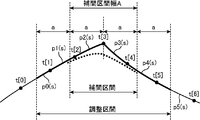
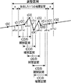
- This adjustment section (see FIGS. 9 and 10) is a section in which the interpolation section is expanded by a section width a that is half of the distribution section width A before and after, and an interpolation block that is a calculation target of the post-interpolation function described later is determined. The standard.
- the local interpolation unit 14c initially sets the post-interpolation integration function stored in the memory 5 to 0 (step S24).
- the local interpolation unit 14c extracts an interpolation block that is a command block for a leading end path for performing an interpolation process for obtaining a post-interpolation function described later (step S26).
- the local interpolation unit 14c includes a plurality of command blocks (in FIG. 9, front-end path command blocks p0 (s) to p5 (s) including at least a part of the adjustment interval obtained in step S22.
- the command block p0 (s) to p7 (s)) for the leading path is selected, and among those command blocks, the interpolation path for obtaining the post-interpolation function to be described later is not completed and the most leading path is selected.
- a block located near the starting point of is extracted as an interpolation block.
- the local interpolation unit 14c obtains a post-interpolation function of the extracted interpolation block (step S28).
- the local interpolation unit 14c obtains a post-interpolation function using a linear distribution function f (s).
- the linear partition function f (s) is expressed by the following equation (4).
- f (s) 0 outside the distribution interval ⁇ A / 2 ⁇ s ⁇ A / 2.
- the local interpolation unit 14c In calculating the post-interpolation function, the local interpolation unit 14c firstly integrates an interval [s ⁇ that has a section width equal to the distribution section width A, with each first position s having a different parameter in the extracted interpolation block as the center. A / 2, s + A / 2] are set. The local interpolation unit 14c then performs first-order differentiation pi ′ (S) based on the leading path parameter at each second position S in which the parameter in the set integration interval [s ⁇ A / 2, s + A / 2] is different. And the first derivative pi ′ (S) at each second position S is distributed based on the distribution function f (s) in the distribution section having the second position S as the center and the distribution section width A.
- the post-distribution differential function pi ′ (S) ⁇ f (s ⁇ S) obtained in this case is integrated over the integration interval [s ⁇ A / 2, s + A / 2], thereby obtaining the post-interpolation function qi ′ (s). .
- the local interpolation unit 14c obtains the post-interpolation function qi '(s) of the interpolation block pi (s) by the following equation (5).
- the post-interpolation function qi '(s) obtained in this way is expressed in different forms depending on whether the section width of the interpolation block pi (s) is larger or smaller than the interpolation section width A.
- the post-interpolation function qi ′ (s) in each case is as follows.
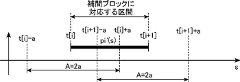
- the post-interpolation function qi ′ (s) obtained by the above interpolation processing is expressed as t [i] ⁇ a ⁇ s ⁇ t [i] + a below function qi11 ′ (s) and t [i ] Function qi12 ′ (s) in the interval of + a ⁇ s ⁇ t [i + 1] ⁇ a and function qi13 ′ (s) in the interval of t [i + 1] ⁇ a ⁇ s ⁇ t [i + 1] + a.
- the command point is t [i]
- the command point near the end point of the leading path is t [i + 1]
- the section width half of the interpolation section width A is a
- the section corresponding to the interpolation block pi (s) is t [I] ⁇ s ⁇ t [i + 1]
- a relationship of t [i] ⁇ a ⁇ t [i + 1] ⁇ a ⁇ t [i] + a ⁇ t [i + 1] + a holds see FIGS.
- FIG. 12 shows a case where the interval width of the interpolation block pi (s) is smaller than the interpolation interval width A and larger than the interval width a half of the interpolation interval width A.
- FIG. 13 shows the interpolation block pi. The case where the section width of (s) is smaller than the half section width a of the interpolation section width A is shown.
- the primary differential function pi '(s) by the parameter s of the interpolation block pi (s) in these cases is represented by a thick line in FIGS.
- the post-interpolation function qi ′ (s) obtained by the above interpolation processing is expressed by the following function qi21 ′ (s) in the interval of t [i] ⁇ a ⁇ s ⁇ t [i + 1] ⁇ a and t
- the function qi22 ′ (s) in the interval [i + 1] ⁇ a ⁇ s ⁇ t [i] + a is subdivided into the function qi23 ′ (s) in the interval t [i] + a ⁇ s ⁇ t [i + 1] + a. Is done.
- the local interpolation unit 14c adds the obtained post-interpolation function to the post-interpolation integration function stored in the memory 5 (step S30).
- the post-interpolation function is added to the post-interpolation integration function set to 0 in step S24, the post-interpolation integration function after the addition is equal to the post-interpolation function obtained in step S28.
- step S32 whether or not the local interpolation unit 14c has performed an interpolation process for obtaining post-interpolation functions for all interpolation blocks whose adjustment sections include at least a part of the sections and adding the post-interpolation functions to the post-interpolation integration function. Is determined (step S32). If the local interpolation unit 14c determines that the interpolation processing for all the interpolation blocks has not been completed yet, the local interpolation unit 14c returns to step S26 and extracts an interpolation block to be subjected to the interpolation processing next.
- the interpolation block extracted at this time is a command block adjacent to the end point side of the front end path with respect to the interpolation block previously subjected to the interpolation processing among the command blocks including at least a part of the adjustment section.
- the local interpolation unit 14c calculates the post-interpolation function in step S28 for the extracted interpolation block, and adds the post-interpolation function obtained thereby to the post-interpolation integration function.
- the local interpolation unit 14c determines that the process of steps S26 to S30 has been completed in step S32 by completing interpolation processing (distribution, integration, addition) of all interpolation blocks whose at least part is included in the adjustment section. Repeat.
- the local interpolation unit 14c determines in step S32 that the interpolation process has been completed for all the interpolation blocks that include at least a part of the adjustment section, the local interpolation unit 14c then obtains a tip interpolation path with an error (step S34). Specifically, the local interpolation unit 14c obtains a front-end interpolation path with an error by extracting a section corresponding to the interpolation section extracted in step S20 from the post-interpolation integration function obtained by adding the post-interpolation functions.
- the error correction unit 14d of the path local filter 14b corrects the tip error correction for correcting the error between the tip path at the point corresponding to the start point of the interpolation section and the point corresponding to the end point of the tip interpolation path with error.
- a path is obtained (step S36). Specifically, the error correction unit 14d has the value of the tip error correction path at the start point of the interpolation interval equal to the value obtained by subtracting the value of the tip path at the start point from the value of the tip interpolation path with error at the start point.
- a tip error correction path that satisfies the condition that the value of the tip error correction path at the end point of the interpolation section is equal to the value obtained by subtracting the tip path value at the end point from the value of the tip interpolation path with error at the end point is obtained.
- the error correction unit 14d sets the tip error correction path to E (s), the tip interpolation path with error to r (s), the tip path to p (s), and the starting point of the interpolation section to Ss.
- a tip error correction path E (s) that satisfies the following equations (12) and (13) is obtained.
- the error correction unit 14d obtains a tip error correction path in which E (Ss) and E (Se) are connected by a straight line as an example of the tip error correction path E (s) that satisfies this condition.
- the error correction unit 14d corrects the tip interpolation path with error by the tip error correction path obtained in step S36, and replaces the corrected tip interpolation path with the interpolation section of the tip path to perform interpolation after local interpolation.
- the leading end path of the section is set (step S38). Specifically, the error correction unit 14d corrects the tip interpolation path with error by subtracting the tip error correction path from the tip interpolation path with error, and the tip with error with respect to the tip path at the start point of the interpolation section is obtained by the correction.
- the error of the interpolation path and the error of the tip interpolation path with error with respect to the tip path at the end point of the interpolation section are removed.
- the corrected front end interpolation path is continuously connected to the front end path at the start point of the interpolation section, and is continuously connected to the front end path at the end point of the interpolation section.
- the local interpolation unit 14c determines whether or not the local interpolation of all the interpolation sections of the tip path has been completed (step S40).
- the processes after step S20 are repeated.
- the local interpolation unit 14c extracts an interpolation section that is located closest to the start point of the tip path from among the interpolation sections for which local interpolation has not ended, and calculates and interpolates a post-interpolation function for the extracted interpolation section. Addition to the post-integration function, derivation of the leading end interpolation path with error, derivation of the leading end error correction path, correction of the leading end interpolation path with error, and the like are performed.
- the local interpolation unit 14c determines that the local interpolation has been completed for all the interpolation sections of the front end path
- the local interpolation process for the front end path by the path local filter 14b ends.
- the path local filter 14b derives a post-local interpolation front end path that is a front end path in which all interpolation sections are locally interpolated.
- the path local filter 14b performs local interpolation of the sky path in the same manner as the local interpolation processing of the tip path described above, and derives a post-local interpolation sky path that is a sky path obtained by locally interpolating all the interpolation sections.
- the posture adjustment information deriving unit 16 derives posture adjustment information (step S5 in FIG. 3).
- the detailed process of deriving posture adjustment information by the posture adjustment information deriving unit 16 is shown in FIG.
- the posture adjustment information derivation unit 16 first targets the post-local interpolation front-end path and the local interpolation for a section in which the first derivative by the parameter s of the front-end post-local interpolation continuously changes. It is checked whether or not there is a posture adjustment point where the posture of the tool 106 should be adjusted so that the change in the direction of the tool axis vector becomes gentle in the rear sky path. If there is a posture adjustment point, the posture including the posture adjustment point is included. The adjustment section is extracted together with the connection condition and the section type of the posture adjustment section, and the information is registered in the memory 5 as posture adjustment information (step S42).
- the posture adjustment information deriving unit 16 increases / decreases the angle formed by the tool axis vector with respect to the traveling direction of the post-local interpolation tip path during a short moving distance (set as a parameter).
- the section (ss, se) of the parameter s with a section width corresponding to a certain parameter before and after the location is used as the posture adjustment section.
- the information of the set posture adjustment section (ss, se) is registered in the memory 5 and the information that the section type of the posture adjustment section (ss, se) corresponds to the section type 2 is registered in the memory 5. To do.
- the posture adjustment information deriving unit 16 includes a control line including a point on the projected tip path at the start point ss of the posture adjustment section (ss, se) and a straight line passing through a point on the projected sky path at the start point ss and the specific plane.
- the angle Cs between the reference direction (y-axis direction) on the (xy plane), the point on the projection tip path at the end point se of the posture adjustment section (ss, se), and the projection sky path at the end point se Both the control line composed of a straight line passing through the point and the angle Ce between the reference direction on the specific plane are registered in the memory 5 as NULL.
- the posture adjustment information deriving unit 16 corresponds to the tip point from the tip point on the tip path after the local interpolation in which the locus indicated by the projected tip path and the locus indicated by the projected sky path are separated from each other on the specific plane.
- the rate of change of the direction of the projected tool axis vector obtained by projecting the tool axis vector toward the sky point on the sky path after local interpolation onto the specific plane with respect to the increment of the parameter (projection tool axis vector (control line) to the parameter increment) If there is a posture adjustment location where the angle change rate with respect to the reference direction exceeds a certain rate of change set as a parameter (see FIG.
- the posture adjustment information deriving unit 16 also includes a point on the projected tip path corresponding to the start point ss of the posture adjustment section (ss, se) and a point on the projected sky path corresponding to the point (on the projected sky path at the start point ss).
- An angle Cs between a control line that is a straight line passing through the point) and the reference direction (hereinafter referred to as an angle Cs of the control line at the start point of the posture adjustment section) and an end point se of the posture adjustment section (ss, se).
- An angle Ce (hereinafter referred to as a reference line) between a control line that is a straight line passing through a point on the corresponding projection tip path and a point on the projection sky path corresponding to the point (a point on the projection sky path at the end point se).
- the control line angle Ce at the end point of the posture adjustment section is obtained, and information on the angle range (Cs, Ce) of the control line in the posture adjustment section (ss, se) is registered in the memory 5.
- the posture adjustment information deriving unit 16 performs the interpolation on the post-local interpolation tip path corresponding to the intersecting or touching point.
- the point becomes a singular point, and a section having a specific section width (set as a parameter) before and after the parametric variable of the singular point.
- the posture adjustment section is set, and information on the posture adjustment section (ss, se) is registered in the memory 5.
- the posture adjustment information deriving unit 16 obtains an angle between the control line at the start point ss and the end point se and the tangent direction of the projection tip path, and based on the angle, at the start point ss and the end point se It is determined whether the control line is nearly parallel to the tangential direction of the projection tip path, and the posture adjustment section is divided into a plurality of sections as follows according to the determination result, and the section for each divided section The information, the angle range of the control line, and the section type are obtained and registered in the memory 5.
- the posture adjustment information deriving unit 16 uses the smaller angle of the angles between the control line at the start point ss and the end point se of the posture adjustment section and the tangential direction of the projected tip path as a parameter stored in the storage unit 4. If the angle is equal to or greater than a specific angle (for example, a specific angle between 10 degrees and 30 degrees), it is determined that the control line is not nearly parallel to the tangential direction of the projection tip path, and the angle is less than the determined angle If it is, it is determined that the control line is nearly parallel to the tangential direction of the projection tip path.
- a specific angle for example, a specific angle between 10 degrees and 30 degrees
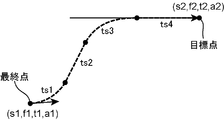
- the posture adjustment information deriving unit 16 has the control lines close to parallel to the tangential direction of the projection tip path at both the start point ss and the end point se of the posture adjustment section. If there is not (see FIG. 17), the posture adjustment section is the start point side section from the start point to the parameter of the intersection of the projection tip path and the projection sky path, and the end point from the parameter of the intersection point to the end point of the posture adjustment section. It divides
- the posture adjustment information deriving unit 16 is configured so that the control line is not nearly parallel to the tangential direction of the projection tip path at the start point ss of the posture adjustment zone and the posture adjustment zone when the projection tip path and the projection sky path intersect.
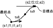
- the control line is close to the tangent direction of the projected tip path at the end point se (see FIG.
- the posture adjustment section is divided into two sections, the start point side section corresponds to section type 1, the end point side first section corresponds to section type 1, and the end point side second section corresponds to section type 2. .
- the posture adjustment information deriving unit 16 obtains the control line angle Cs at the start point of the posture adjustment section and the control line angle Ce at the end point of the posture adjustment section, and calculates the average angle between the obtained angles Cs and Ce. It is obtained as the angle Cm of the control line at the intersection of the projected tip path and the projected sky path.
- the posture adjustment information deriving unit 16 derives an angle equal to the control line angle Ce at the end point of the posture adjustment section as the control line angle Ck at the division point.
- the posture adjustment information deriving unit 16 corresponds to the intersection of a straight line passing through a point on the projection tip path corresponding to the division point sk and having an angle between the reference direction and Ck and the projection sky path.
- the parametric position is obtained as a division point Sk of the projection sky path.
- the posture adjustment information deriving unit 16 controls the control line at the start point ss of the posture adjustment section that is close to the tangential direction of the projection tip path and at the end point se of the posture adjustment section. If the line is not nearly parallel to the tangential direction of the projected tip path, the starting point from the starting point of the posture adjustment section to the dividing point between the start point and the parameter of the intersection of the projected tip path and the projected sky path.
- the posture adjustment section is divided into the first section, the second section on the start point side from the dividing point to the parameter of the intersection of the projection tip path and the projection sky path, and the end point side section from the intersection point to the end point of the posture adjustment section.
- the start point side first section corresponds to the section type 2
- the start point side second section corresponds to the section type 1
- the end point side section corresponds to the section type 1.
- the posture adjustment information deriving unit 16 calculates the control line angle Cs at the start point of the posture adjustment interval, the control line angle Ce at the end point of the posture adjustment interval, and the control line angle Cm at the intersection of the projection tip path and the projection sky path.
- an angle equal to the control line angle Cs at the start point of the posture adjustment section is derived as the control line angle Ck at the dividing point. Further, the posture adjustment information deriving unit 16 obtains the division point Sk of the projected sky path in the same manner as described above. Then, from the information obtained as described above, the posture adjustment information deriving unit 16 starts the first point side first section (ss, sk) for the tip path and the first point side first section (Ss, Sk) for the sky path (Ss).
- the posture adjustment information deriving unit 16 has a control line that is nearly parallel to the tangential direction of the projection tip path at both the start point ss and the end point se of the posture adjustment section when the projection tip path and the projection sky path intersect.
- the posture adjustment section is the start point side section from the start point to the parameter of the intersection of the projection tip path and the projection sky path, and the end point side from the parameter of the intersection to the end point of the posture adjustment section. It is determined that both the start-point side section and the end-point side section fall under section type 2.
- the posture adjustment information deriving unit 16 also includes a parameter sm for the projection tip path and a parameter Sm for the projection sky path at the intersection of the projection tip path and the projection sky path, and an angle Cs of the control line at the start point of the posture adjustment section.
- the control line angle Ce at the end point of the posture adjustment section and the control line angle Cm at the intersection are obtained in the same manner as described above.
- the control line corresponds to the tangential direction of the projection tip path at both the start point ss and the end point se of the attitude adjustment section.
- the posture adjustment section is defined as the end point of the posture adjustment section from the start point side section from the start point to the parameter of the contact point between the projection tip path and the projection sky path and the contact point variable. It is determined that both the start-point side section and the end-point side section correspond to the section type 2.
- the posture adjustment information deriving unit 16 calculates the start point Ss and end point Se of the posture adjustment section for the sky path, the control line angle Cs at the start point of the posture adjustment section, and the control line angle Ce at the end point of the posture adjustment section.
- the parameter sm for the projection tip path at the contact point and the parameter Sm for the projection sky path are determined in the same manner as the parameter variables sm and Sm for the intersection in the case of FIG. Is obtained in the same manner as the angle Cm of the control line at the intersection point in the case of FIG.
- the posture adjustment information deriving unit 16 registers, in the memory 5, information having the same contents as in the case of FIG. 19 as posture adjustment information for the start point side section from the obtained information, and as posture adjustment information for the end point side section. Information similar to that in the case of FIG. 19 is registered in the memory 5.
- the posture adjustment information deriving unit 16 has a singular point where the length of the projected tool axis vector is zero on the tip path after local interpolation and the sky path after local interpolation (singular point where the tool axis vector is perpendicular to a specific plane) ) Are continuous (hereinafter referred to as a singular point continuous section), a section having a specific section width before and after the singular point continuous section is set as the posture adjustment section.
- the posture adjustment information deriving unit 16 has a control line that is not nearly parallel to the tangential direction (traveling direction) of the projected tip path at the start point ss of the posture adjustment interval including the singular point continuous interval, and the end point of the posture adjustment interval If the control line is close to parallel to the tangential direction (traveling direction) of the projection tip path at se (see FIG. 22), it is located slightly closer to the end point from the start point ss of the posture adjustment section and the start point of the singular point continuous section.
- the posture adjustment section is divided into the end point side section from sn to the end point se of the posture adjustment section, and it is determined that the start point side section and the intermediate section correspond to the section type 1 and the end point side section corresponds to the section type 2.
- the posture adjustment information deriving unit 16 obtains the first division point Sm in the sky path as an intermediary variable equal to the first division point sm, and mediates the second division point Sn in the sky path equal to the second division point sm. Find as a variable.
- Information on the angle range (Cs, Cm) of the control line in the start point side section and information that the start point side section corresponds to the section type 1 is registered in the memory 5 as posture adjustment information, and the intermediate section (sm, sn) about the tip path
- the intermediate section (Sm, Sn) for the sky path, the angle range (Cm, Cn) of the control line in the intermediate section, and information that the intermediate section corresponds to the section type 1 are registered in the memory 5 as posture adjustment information
- End point side section (sn, se) for the path, end point side section (Sn, Se) for the sky path (Se se)
- control line angle in the end point side section Circumference (Cn, Ce) and end point section is registered in the memory 5 the information that corresponds to the interval type 2 as the posture adjustment information.
- the posture adjustment information deriving unit 16 has a case in which the control line is nearly parallel to the tangential direction (traveling direction) of the projection tip path at both the start point ss and the end point se of the posture adjustment section including the singular point continuous section (see FIG. 23) includes a starting point side section between the starting point ss of the posture adjustment section and the first dividing point sm located slightly closer to the end point from the starting point of the singular point continuous section, and the first dividing point sm and the singular point continuous section.
- the posture adjustment section is divided into an intermediate section between the second division point sn positioned slightly closer to the start point from the end point of the image and an end point side section from the second division point sn to the end point se of the posture adjustment section.
- the posture adjustment information deriving unit 16 includes the first division point Sm in the sky path, the second division point Sn in the sky path, the control line angle Cs and the posture at the start point of the posture adjustment section. An angle Ce of the control line at the end point of the adjustment section is obtained. The posture adjustment information deriving unit 16 sets the angle Cm of the control line at the first division point to an angle equal to the angle between the traveling direction of the projection tip path at the first division point and the reference direction, and performs the second division.
- the control line angle range (Cs, Cm) and the information that the start point side section corresponds to the section type 2 are registered in the memory 5 as posture adjustment information, and the intermediate section (sm, sn) for the tip path is registered.
- the posture adjustment information deriving unit 16 determines whether or not each section registered in the memory 5 includes a section in which the direction specifying function C (s) and the tip sky corresponding adjustment function S (s) are not set. It discriminate
- the posture adjustment information deriving unit 16 determines that there is a section in which the both functions C (s) and S (s) are not set in the section registered in the memory 5, then the both functions C One section is extracted from the sections for which (s) and S (s) are not yet set, and it is determined whether or not the section type of the extracted section is section type 1 (step S46). At this time, the posture adjustment information deriving unit 16 determines the section type of the extracted section based on the section type information registered for the section in the memory 5.
- the posture adjustment information deriving unit 16 determines that the section type of the extracted section is the section type 1, the posture adjustment information deriving section 16 derives the direction specifying function C (s) of the section and uses the derived function C (s). It is additionally registered in the memory 5 as posture adjustment information of the section (step S48).
- the posture adjustment information deriving unit 16 calculates the direction specifying function C (s) by the following equation (14).
- the posture adjustment information deriving unit 16 additionally registers the calculated direction specifying function C (s) as posture adjustment information in the memory 5 in association with the corresponding section information. After step S48, the process returns to step S44, and the subsequent processing is repeated.
- the posture adjustment information deriving unit 16 determines in step S46 that the section type of the extracted section is not the section type 1, that is, the section type 2, the posture adjustment information deriving unit 16 For the extracted section, the tip top sky corresponding adjustment function S (s) is derived, and the derived function S (s) is additionally registered in the memory 5 as posture adjustment information of the section (step S52).
- the attitude adjustment information deriving unit 16 differs in the parameter in the section from the point corresponding to the start point of the extracted section in the sky path after the local interpolation, when deriving the leading end sky corresponding adjustment function S (s).
- the moving distance along the sky path after the local interpolation to the point corresponding to each point Stipulated the correlation between the parameters for the tip path after the local interpolation and the parameter for the sky path after the local interpolation so that the moving distance along the tip path after the local interpolation is maintained at a constant ratio
- An adjustment function S (s) corresponding to the tip sky is obtained.
- the posture adjustment information deriving unit 16 sets a plurality of intermediate points in the posture adjustment section (ss, se), and starts from the point corresponding to the start point ss of the posture adjustment section in the post-local interpolation tip path. From the point corresponding to each intermediate point and the movement distance along the tip path after the local interpolation to the point corresponding to the end point se, and from the point corresponding to the start point ss of the posture adjustment section of the post-local interpolation sky path to each intermediate point The movement distance along the sky path after the local interpolation up to the corresponding point and the point corresponding to the end point se is derived, respectively. For example, as shown in FIG.
- the start point s0 is set as a point equal to the start point ss of the posture adjustment section
- the end point s5 is set as a point equal to the end point se of the posture adjustment section
- the start point s0 and the end point s5 are Four intermediate points s1, s2, s3, and s4 are set in between.
- the posture adjustment information deriving unit 16 starts from the point p (s0) on the post-local interpolation tip path corresponding to the start point s0 to the post-local interpolation tip path corresponding to each of the intermediate points s1, s2, s3, s4 and the end point s5.
- the posture adjustment information deriving unit 16 correlates an arbitrary parameter in the posture adjustment section and a movement distance along the post-local interpolation tip path corresponding to the section from the starting point of the posture adjustment section to the arbitrary parameter.
- a distance calculation function len (s) on the tip path indicating the relationship is derived.
- the posture adjustment information deriving unit 16 obtains the points (s0, len0), (s1, len1), (s2, len2), (s3, len3), (s4, len4), (s5, len5).
- a function representing curves connected in order is derived as a tip path distance calculation function len (s) (s0 ⁇ s ⁇ s5).
- the posture adjustment information deriving unit 16 also adds an arbitrary travel distance along the post-local interpolation sky path from the point on the post-local interpolation sky path corresponding to the start point of the posture adjustment section, and the post-local interpolation sky path by the travel distance.
- An upper path distance-parameter variable function SS (LEN) indicating a correlation with a parameter of a point separated from the point corresponding to the starting point of the posture adjustment section along the upper path after local interpolation is derived.
- the posture adjustment information deriving unit 16 obtains the points (LEN0, s0), (LEN1, s1), (LEN2, s2), (LEN3, s3), (LEN4, s4), (LEN5, s5).
- a function representing a curve connected in order is derived as a sky path distance-parametric variable corresponding function SS (LEN) (LEN0 ⁇ LEN ⁇ LEN5). Then, the posture adjustment information deriving unit 16 calculates the tip upper sky correspondence adjustment function S (s) based on the derived tip path upper distance calculation function len (s) and the sky path upper distance-parametric variable corresponding function SS (LEN). To derive. Specifically, the posture adjustment information deriving unit 16 derives the function S (s) by the following equation (15).
- the posture adjustment information derivation unit 16 additionally registers the tip sky corresponding adjustment function S (s) derived as described above in the memory 5 as part of the posture adjustment information. Thereafter, the process returns to step S44 and the subsequent processing is repeated.
- the parameter time function deriving unit 18 derives a parameter time function that represents a change in the parameter with respect to the passage of the reference time T (FIG. 3). Step S6).
- the parameter time function deriving unit 18 includes an acceleration / deceleration condition including an allowable acceleration for each transfer axis stored in the storage unit 4, a front-end path after local interpolation, an empty path after local interpolation, a memory
- the parameter time function (parameter variable velocity curve) is obtained by using the transfer axis coordinate calculation function based on the posture adjustment information registered in 5.
- the parameter time function deriving unit 18 obtains the parameter time function as follows.
- the parametric variable time function deriving unit 18 first obtains a parametric variable speed upper limit function represented by a stepped velocity curve in FIG.
- the parametric variable speed upper limit function is a function that represents the upper limit value of the speed ds / dT of the parametric variable s for each block between the command points of each transfer axis path.
- Each horizontal part of the stepwise speed curve in FIG. 24 represents a block, and the speed ds / dT of the part corresponds to the upper limit value of the speed ds / dT of the parameter s of the block.
- Each block is originally set so that the increment of the parameter s for each block is equal, but the time required to travel a distance corresponding to the increment of the parameter s of each block varies. In FIG.
- the increase in the parameter s is converted into the progress of the time t and is represented on the horizontal axis.
- the parametric variable time function deriving unit 18 obtains the parametric variable upper limit function by obtaining the upper limit value of the speed ds / dT of the parametric variable s of each block as follows.
- the parametric time function deriving unit 18 determines the target based on the tip after local interpolation and the sky path after local interpolation.
- a total of five points (s a -2e, s a -e, s a , s a + e, s a + 2e) of a predetermined parameter s a in the block and two points before and after the point Determine the position coordinates of each tip point on the tip path after local interpolation and each tool axis vector from each tip point to the corresponding sky point on the sky path after local interpolation.
- the parametric variable time function deriving unit 18 corresponds to a section where the target block is registered as posture adjustment information in the memory 5, and the direction specifying function C (s) is registered in the memory 5 for the section.
- a total of five points s a -2e, s a -e, s a , s a + e, each of a point of a predetermined parameter s a in the target block and two points before and after the point.
- the direction specifying angle corresponding to the five parameter positions is obtained using the direction specifying function C (s) of that section.
- the parametric time function deriving unit 18 corresponds to a section in which the target block is registered as posture adjustment information in the memory 5, and the leading sky corresponding adjustment function S (s) is registered in the memory 5 for the section.
- a total of five points s a -2e, s a -e, s a , s a , a point of a predetermined parameter s a in the target block and two points before and after that point. + E, s a + 2e)
- the position coordinates of each tip point on the post-local interpolation tip path are calculated, and the five points based on the tip sky corresponding adjustment function S (s) for the section corresponding to the target block are obtained.
- e is a parameter indicating a minute distance in the parameter.
- i 1 to the point (s a -e)
- i 2 to the point s a
- the parameter time function deriving unit 18 obtains an approximate value ds1 [ax] of the first derivative by the parameter of the transfer axis path at the point (s a -e) by the following equation (16), and by the following equation (17):
- the approximate value ds2 [ax] of the first derivative by the parameter of the transfer axis path at the point (s a + e) is obtained, and the two approximate values ds1 [ax] and ds2 [ax] thus obtained and the following equation (18) are used.
- an approximated value ddds [ax] of the second derivative by the parameter of the transfer axis path at the point corresponding to the parameter s a is obtained.
- ax is an index representing each transfer axis.
- the acceleration a [] for each transfer axis can be approximated by v 2 ⁇ ddss [] and is stored in the storage unit 4.
- the allowable acceleration for each transfer axis in the acceleration / deceleration condition is A []
- the parameter time function deriving unit 18 obtains the speed upper limit value vm of the target block by the following equation (19).
- the parameter time function deriving unit 18 determines the speed upper limit value vm of the corresponding block for each transfer axis and the speed corresponding to the block among the speed commands included in the machining program. The lowest value is the upper limit value of the speed ds / dT of the parameter s of the block.
- the parametric variable time function deriving unit 18 obtains the upper limit value of the speed ds / dT of the parametric variable s of all the blocks by the method as described above, and connects the obtained upper limit values of the blocks to the parametric variable speed upper limit function. Ask for.
- the parametric variable time function deriving unit 18 has a stepped shape represented by the parametric variable upper limit function based on the allowable speed, allowable acceleration, and allowable jerk of the variable s included in the acceleration / deceleration conditions stored in the storage unit 4.
- An acceleration / deceleration curve ds (T) / dT that continuously changes so as not to exceed the velocity curve is obtained, and the obtained acceleration / deceleration curve ds (T) / dT is integrated at the reference time T to obtain a parameter time function s (T ) Is calculated.
- the parameter time function deriving unit 18 first sets a predetermined time interval from the start point side to the end point side of the acceleration region speed curve (speed function) of the acceleration / deceleration curve ds (T) / dT. Every time it is obtained sequentially along with the time interval width ts of the time interval and registered in the memory 5. At this time, the parameter time function deriving unit 18 reaches the end point of the block set as the target point (s2, f2) from the final point (s1, f1, t1) of the velocity curve registered in the memory 5 so far.
- a speed curve is calculated for each time interval together with the time interval width ts so that the speed f1 at the final point can rise to the upper limit value (speed upper limit value f2) of the speed ds / dT of the block.
- the form of the speed curve obtained at this time is the difference (s2 ⁇ s1) in the parameter between the final point and the target point, the speed f1 at the final point, the speed upper limit f2, the acceleration a1 at the final point, the allowable value It depends on conditions such as acceleration and allowable jerk.
- FIGS. 25 to 31 show how to obtain a velocity curve corresponding to each condition.
- FIG. 25 and 26 show a case where the speed reaches the speed upper limit value f2 before reaching the target point (s2, f2) from the final point (s1, f1, t1).
- t2 is the time when s2 is reached.
- FIG. 25 shows that the speed is increased from f1 so that the acceleration increases from a1 to the allowable acceleration according to the allowable jerk from the final point (s1, f1, t1) (time interval ts1), and then the allowable acceleration is reached.
- the speed increases at the same acceleration (time interval ts2), and then the acceleration is reduced according to the allowable jerk so that the speed does not exceed the speed upper limit value f2, and the speed reaches the speed upper limit value f2 (time interval ts3).
- a speed curve in the form of reaching the target point (s2, f2) at a speed equal to the speed upper limit value f2 (time interval ts4) is shown, and the parametric variable time function deriving unit 18 follows each condition according to such a condition.
- Each speed curve (speed function) is calculated together with the time interval widths ts1 to ts4 of each interval, and the calculated speed curve is stored in the memory 5 together with the corresponding time interval. To record.
- the speed is increased from f1 so that the acceleration increases from a1 according to the allowable jerk from the final point (s1, f1, t1) (time interval ts5).
- the acceleration is reduced according to the allowable jerk to reach the speed upper limit value f2 (time interval ts6), and then the target point (s2, f2) is reached at a speed equal to the speed upper limit value f2 (time interval ts7).
- the parameter time function deriving unit 18 calculates a speed curve (speed function) for each time interval together with the time interval widths ts5 to ts7 of each interval in accordance with such conditions. The calculated speed curve is registered in the memory 5 together with the corresponding time interval.
- FIGS. 27 to 29 show a case where the target point (s2, f2) is reached while the acceleration is decreasing according to the allowable jerk.
- the speed is increased from f1 so that the acceleration increases from a1 according to the allowable jerk from the final point (s1, f1, t1) (time interval ts8), but from the final point to the target point (s2 , F2) is small (s2-s1), so before the speed reaches the allowable acceleration, the acceleration is reduced according to the allowable jerk to reach the speed upper limit value f2 and reach the target point (s2, f2).
- the parameter time function derivation unit 18 converts the speed curve (speed function) for each time interval according to such a condition to the time interval width ts8 of each interval. , Ts9, and the calculated velocity curve is registered in the memory 5 together with the corresponding time interval.
- the speed is increased from f1 so that the acceleration increases from a1 to the allowable acceleration according to the allowable jerk from the final point (s1, f1, t1) (time interval ts10), and thereafter, at an acceleration equal to the allowable acceleration.
- the speed increases (time interval ts11), and then reaches the target point (s2, f2) (time interval ts12) while the acceleration is decreased according to the allowable jerk so that the speed does not exceed the upper speed limit f2.
- the parameter time function deriving unit 18 calculates a speed curve (speed function) for each time interval together with the time interval widths ts10 to ts12 of each interval according to such a condition, The calculated speed curve is registered in the memory 5 together with the corresponding time interval.
- the parameter time function deriving unit 18 calculates the speed curve (speed function) of the section together with the time section width ts13 in accordance with such a condition, and the calculated speed curve is used as the time section. It is registered in the memory 5 together with ts13.
- FIG. 30 shows a case where the speed cannot be increased to the speed upper limit value f2 even if the parameter s reaches the value s2 corresponding to the target point.
- the parameter time function deriving unit 18 calculates a speed curve and does not register the calculated speed curve in the memory 5 when this is the case.
- T1 shows a case where the speed exceeds the speed upper limit f2 even if the acceleration is decreased according to the allowable jerk.
- the parametric time function deriving unit 18 cancels the data of the speed curve registered in the memory 5 immediately before when calculating the speed curve, and further stores the memory in the previous one. Recalculation is performed to obtain a speed curve that reaches the current target point from the final point of the speed curve registered in 5 and can reach the speed upper limit value corresponding to the current target point.
- the recalculation method in this case is the same as in the above cases.
- the parameter time function deriving unit 18 sequentially calculates and registers the speed curve as described above.
- the parameter time function deriving unit 18 registers the obtained velocity curve in the memory 5
- the time t2 and the acceleration a2 when reaching the target point are registered in the memory 5 and the next target point is set.
- the registered time t2 is used as the time t1 at the final point
- the registered acceleration a2 is used as the acceleration a1 at the final point to calculate the next speed curve.
- the speed curve in the acceleration region of the acceleration / deceleration curve is obtained by the speed curve obtained until the speed upper limit value corresponding to the next target point becomes smaller than the speed at the final point.
- the parameter time function deriving unit 18 sequentially calculates and registers the speed curve similar to the above from the end point side to the start point side of the path in the acceleration / deceleration curve. Obtain the velocity curve. Then, the parametric variable time function deriving unit 18 obtains the acceleration / deceleration curve ds (T) / dT by connecting the end point of the obtained acceleration region speed curve and the start point of the deceleration region speed curve. Then, the parameter time function deriving unit 18 calculates the parameter time function s (T) by integrating the obtained acceleration / deceleration curve ds (T) / dT at the reference time T.
- step S7 The detailed process of this step S7 is shown in the flowchart of FIG.
- the transfer command deriving unit 20 initially sets the reference time T so that the reference time T matches the time that is the starting point of the parametric variable time function obtained in step S6.
- the position coordinate of the transfer axis is set to oldp [] (step S56 in FIG. 6).
- the transfer command deriving unit 20 obtains a parameter position s corresponding to the initially set reference time T (step S58). Specifically, the transfer command deriving unit 20 obtains the parameter position s corresponding to the initially set reference time T using the parameter time function s (T) obtained by the parameter time function deriving unit 18. .
- the transfer command deriving unit 20 calculates each transfer axis coordinate newp [] corresponding to the determined parameter position s using the transfer axis coordinate calculation function (step S60). The detailed process of this step is shown in the flowchart of FIG.
- the transfer command deriving unit 20 determines whether or not the parameter position s derived in step S58 is a parameter within the section of the posture adjustment information registered in the memory 5 (step S76).
- the parameter position is next. It is determined whether or not the tip top sky corresponding adjustment function S (s) is registered in the memory 5 as posture adjustment information corresponding to the section corresponding to s (step S78).
- the transfer command deriving unit 20 determines that the tip over sky adjustment function S (s) is not registered in the memory 5 as the posture adjustment information corresponding to the section, next, in step S58 described above.
- a variable ss is obtained (step S80). Specifically, the transfer command deriving unit 20 uses a control line corresponding to the parameter position s derived in step S58 using the direction specifying function C (s) included in the posture adjustment information corresponding to the section.
- a direction specific angle which is an angle between the reference direction, is obtained, and passes through a projected tip point obtained by projecting the tip point on the post-local interpolation tip path corresponding to the parameter position s derived in step S58 onto the specific plane.
- a parameter ss is calculated for the sky point on the post-local interpolation sky path corresponding to the intersection where the straight line having the obtained direction specific angle with respect to the reference direction intersects the projection sky path.
- the transfer command deriving unit 20 coordinates the tip point p (s) on the post-local interpolation tip path corresponding to the parameter position s derived in step S58 in the reference coordinate system, and the tip point p. From (s), a tool position consisting of a tool axis vector toward the sky point P (ss) corresponding to the parameter ss obtained in step S80 is obtained (step S84).
- the transfer command deriving unit 20 calculates the position coordinates newp [] of each transfer axis corresponding to the obtained tool position (step S86). Specifically, in the transfer command deriving unit 20, the tip point of the tool 106 is arranged at the position coordinate of the tip point p (s) obtained in step S84, and the tool axis vector (axial center) of the tool 106 is set. In order to cause the tool 106 to take a position and orientation that match the tool axis vector obtained in step S84, the table transfer device 102 rotates the table 101a, the swing support transport unit 110b rotates the swing support 110a, and the like.
- the moving support body transfer unit 112b calculates the rotation support body 112a
- the ram transfer unit 114b calculates the ram 114a
- the saddle transfer unit 116b calculates position coordinates on the corresponding transfer shaft.
- the C-axis coordinate is indefinite
- the transfer command deriving unit 20 sets the rotation axis coordinate candidate value obtained in step S82 as the C-axis coordinate.
- step S78 the transfer command deriving unit 20 has the tip sky adjustment function S (s) registered in the memory 5 as posture adjustment information corresponding to the section including the parameter position s derived in step S58. If it is determined that the parameter variable ss (upper sky point specifying parameter) for the above-mentioned interpolated sky path corresponding to the parameter position s derived in step S58 is the tip sky corresponding adjustment function corresponding to that section. It calculates
- S (s) the transfer command deriving unit 20 sets the value obtained by substituting the parameter s derived in step S58 to the tip sky corresponding adjustment function S (s) as the parameter ss.
- the transfer command deriving unit 20 determines whether or not the direction specifying function C (s) is registered in the memory 5 as posture adjustment information corresponding to the section including the parameter position s derived in step S58. (Step S90). Here, if the transfer command deriving unit 20 determines that the direction specifying function C (s) is registered in the memory 5 as the posture adjustment information corresponding to the section, the transfer command deriving unit 20 performs the processing from step S82 onward. On the other hand, when the transfer command deriving unit 20 determines that the direction specifying function C (s) is not registered in the memory 5 as the posture adjustment information corresponding to the section, the transfer command deriving unit 20 is set in step S56.
- a rotation axis coordinate candidate value is set to an angle equal to the rotation transfer axis coordinate (C axis coordinate oldp [Ci]) of the transfer axis coordinates oldp [] (step S92), and then the processing of steps S84 and S86 is performed. I do.
- step S76 If the transfer command deriving unit 20 determines in step S76 that the parameter position s derived in step S58 is not a parameter within the section registered in the memory 5, the transfer command deriving unit 20 determines in step S58.
- a position (parameter variable) equal to the parameter position s derived in step S58 is set as the parameter position ss for the sky point on the post-local interpolation sky path corresponding to the derived parameter position s (step S94). Thereafter, the process of step S92 is performed.
- the transfer command deriving unit 20 sets the position coordinates newp [] for each transfer axis obtained as described above as the old coordinates oldp [] (step S62 in FIG. 6).
- the transfer command deriving unit 20 obtains a new reference time T by adding the reference unit time dT to the reference time T initially set in step S56 (step S64).
- the transfer command deriving unit 20 obtains a parameter position s corresponding to the new reference time T in the same manner as in step S58 (step S66), and on each transfer axis corresponding to the obtained parameter position s.
- the position coordinate newp [] of the current position is obtained (step S68).
- the transfer command deriving unit 20 basically obtains the position coordinates newp [] on each transfer axis according to the flowchart of FIG. 7, as in step S60.
- the rotation is performed at an angle closest to the C axis coordinate oldp [Ci] of the old coordinate oldp [] set in step S62.
- the rotation axis coordinate candidate value is obtained at an angle equal to the C axis coordinate oldp [Ci] of the old coordinate oldp [] set in step S62. Set coordinate candidate values.
- the transfer command deriving unit 20 calculates a command pulse (step S70). Specifically, the transfer command deriving unit 20 corresponds to the old coordinate oldp [] for each transfer axis set in step S62 from the position coordinate newp [] for each transfer axis obtained in step S68. By subtracting, the amount of change in the position coordinates on each transfer axis per reference unit time dT, that is, the transfer amount per reference unit time dT of the object to be transferred for each transfer axis is obtained, and the obtained transfer amount is calculated in real time. The command pulse is used every unit time (every specific cycle).
- the control unit 22 sends the servo motors of the table transfer device 102 and the transfer units 110b, 112b, 114b, and 116b to the corresponding transfer axis among the command pulses per specific period obtained by the transfer command deriving unit 20.
- a command pulse indicating the transfer amount is output (step S72).
- the table transfer device 102 receives the table 101a
- the swing support transport portion 110b receives the swing support 110a
- the swing support transport portion 112b receives the swing support 112a
- the ram transport portion 114b receives the ram 114a.
- the saddle transfer unit 116b moves the saddle 116a along the transfer axis corresponding to the specific period by the transfer amount indicated by the command pulse from the control unit 22, respectively.
- step S74 the transfer command deriving unit 20 determines whether or not to perform a shutdown process.
- the shutdown process is executed, the numerical control process of the present embodiment is terminated, and the transfer command deriving unit 20 does not perform the shutdown. If it is determined, the processes after step S62 are repeated. In step S62 performed again, the transfer command deriving unit 20 sets the position coordinates newp [] for each transfer axis obtained in step S68 to the old coordinates oldp [].
- control process by the numerical controller 2 of the present embodiment is performed.
- the posture adjustment information deriving unit 16 has the posture adjustment section extending before and after the posture adjustment portion where the change rate of the direction of the projection tool axis vector with respect to the parameter increment exceeds a certain change rate.
- the orientation adjustment information for adjusting the orientation of the tool 106 in the direction in which the change of the direction of the projected tool axis vector becomes gentle is obtained, and the transfer command deriving unit 20 performs the local interpolation corresponding to the parameter in the orientation adjustment section.
- the sky point on the post-local interpolation sky path adjusted from the tip point on the tip path to the direction in which the direction of the projected tool axis vector changes gently based on the posture adjustment information.
- the tool axis vector headed to the position is determined, and within the posture adjustment section, the command pulse is derived based on the obtained tool axis vector and the position coordinates of the tip point.
- Orientation Oite projection tool axis vector can be prevented from being suddenly changed. Since the direction of the projection tool axis vector corresponds to the A-axis direction, according to this embodiment, the rotation device 112 causes the swing device 110, the spindle head 108, and the tool 106 to rotate rapidly with respect to the table 101a. Can be prevented. As a result, it is possible to suppress a decrease in workpiece machining accuracy and mechanical shock caused by this sudden rotation.
- the transfer command deriving unit 20 obtains the position coordinates of the tip point corresponding to the parameter in the posture adjustment section on the tip path, and the relative positional relationship from the tip point to the tip point.
- the tool axis vector heading to the sky point on the sky path adjusted based on the posture adjustment information in a direction in which the change in the direction of the projected tool axis vector becomes gentle is obtained, and the position coordinates and tool axis vector of the obtained tip point are obtained. Since the command pulse is derived based on the position of the tool 106, the posture of the tool 106 is adjusted to each tip point on the tip path and each tip point even after adjustment so that the change in the direction of the projected tool axis vector in the posture adjustment section becomes gradual. It is possible to suppress swinging in a direction perpendicular to the curved surface connecting each sky point on the corresponding sky path. This also can suppress a decrease in the machining accuracy of the workpiece.
- the path perpendicular to the specific plane is obtained. It is possible to cause the tool 106 to take a posture in which the tip point of the tool and the sky point overlap each other when viewed from the direction, that is, a posture in which the tool axis vector is perpendicular to a specific plane. In addition, it is possible to effectively prevent the swinging device 110 from rotating relatively rapidly with respect to the table 101a.
- the tip point and the sky point are seen from the direction perpendicular to the specific plane.
- the approach of moving the tool 106 to the swinging device 110 so as to change the inclination of the tool 106 in the A-axis direction in the opposite direction when passing the intersection is performed by moving closer to each other and moving away from each other after passing the intersection. It can be realized by moving it. As a result, it is possible to prevent the tool 106 and the swing device 110 from rotating suddenly in the C-axis direction when passing through the intersection.
- the control line and the reference corresponding to each parameter in the section so that the angle between the control line and the reference direction changes at an equal rate.
- An angle with the direction is obtained, and a tool axis vector in which the positional relationship of the sky point with respect to the tip point is adjusted based on the angle is obtained.
- a command pulse is obtained based on the tool axis vector, and the object to be transferred is transferred in accordance with the command pulse. Therefore, the tool 106 rotated relative to the table 101a by the rotation device 112. And the change of the rotation angle of the rocking
- the direction specific angle obtained from the direction specific function C (s) is used as the C-axis coordinate at the singular point.
- the C-axis coordinate is uniquely determined at the point, and the indefinite state can be eliminated.
- the direction specific angle of this singular point is obtained from a direction specific function that changes the angle between the control line and the reference direction at an equal ratio in the target section, the projection tool axis vector of the target section The condition that the direction is gradually changed is satisfied.
- the direction of the tool 106 and the rotating device 112 is gently changed while eliminating the indefinite state of the position coordinate in the rotational transfer axis direction at the singular point. be able to.
- the moving distance of the tip point along the tip path after local interpolation from the start point of the section and the sky along the sky path after local interpolation from the start point of the section can be moved while the point moving distance is always maintained at a constant ratio. For this reason, it is possible to prevent the posture change of the tool 106 such that the sky point that has been delayed with respect to the tip point suddenly overtakes the tip point, and vice versa. In order for the device 112 to realize such a change in the posture of the tool 106, it is possible to prevent the tool 106 and the swing device 110 from rotating relatively rapidly with respect to the table 101a.
- the local interpolation of the pre-interpolation tip path and the pre-interpolation sky path by the local interpolation unit 14 c of the path local filter 14 b of the path interpolation unit 14 the primary variable based on the parameter in the pre-interpolation tip path and the pre-interpolation sky path is used. Because the differential value is discontinuous, the point where the speed is discontinuous can be interpolated so that the speed is continuous, and the secondary differential value by the parameter in the tip path before interpolation and the sky path before interpolation The points where the acceleration is discontinuous due to the discontinuity can be interpolated so that the acceleration is continuous.
- the differential value due to the parametric variable is discontinuous due to abnormal data in the front path before interpolation and the sky path before interpolation, and the location where sudden speed change or acceleration change occurs due to this is abrupt. It is possible to suppress a change in speed and acceleration, and to suppress the occurrence of a mechanical shock at the location.
- the position where the differential value is discontinuous is interpolated among the front path before interpolation and the empty path before interpolation. The mechanical shock factor can be removed from these paths. For this reason, after the transfer command deriving unit 20 derives the command pulse, it is possible to eliminate an acceleration / deceleration process that interpolates a portion of the command pulse that causes a mechanical shock.
- the pre-interpolation path deriving unit 13 reads the work coordinate system tool path included in the machining program, and converts the read work coordinate system tool path into a path on the reference coordinate system based on the work installation information.
- the reference coordinate system tool path is derived by conversion, and the tip path before interpolation and the pre-interpolation sky path are derived based on the derived reference coordinate system tool path, so that the workpiece coordinate system is inclined with respect to the reference coordinate system.
- the numerical control device according to the present invention can be applied to various machine tools other than the machine tools shown in the above embodiment.
- the numerical control device according to the present invention can be applied to a 5-axis machine tool in which a machine table rotates.
- the numerical controller may not include a path interpolation unit, and based on the tip path and the sky path not interpolated obtained from the tool path of the machining program, the derivation of posture adjustment information, the parameter variable time function Derivation and command pulse may be derived.
- the linear differentiation function is used to distribute the first-order derivative of the leading path and sky path parameters to the distribution interval, but the distribution method is not limited thereto. That is, various distribution functions other than the linear distribution function may be used for the distribution of the first derivative by the parameters of the tip path and the sky path.
- the distribution function used for this distribution is preferably a function having an integral of 1 in the section [ ⁇ A / 2, A / 2] and a symmetrical shape with respect to the center of the section.
- a bell-shaped distribution function f (s) represented by the following equation is given.
- f (s) 0 outside the distribution interval ⁇ A / 2 ⁇ s ⁇ A / 2.
- the interpolation section can be interpolated so as to be a smoother curve than when the above-mentioned linear distribution function is used.
- the first derivative is distributed using the linear distribution function, and the first derivative by the parameter in the path is discontinuous.
- the direction specifying function C (s) is calculated as a linear function.
- the first derivative and the second derivative based on the parameter of the control line angle at the start point and the end point of the posture adjustment section are approximately calculated.
- the direction specifying function that smoothly connects the direction specifying functions before and after the posture adjustment section and smoothly connects the direction specifying functions before and after the end point of the posture adjustment section is preferably obtained.
- the posture adjustment information deriving unit is configured to detect the increment of the parameter of the angle between the projection tool axis vector and the reference direction in a specific plane when the locus indicated by the projection tip path and the locus indicated by the projection sky path are separated from each other.
- the posture adjustment section before and after the posture adjustment point corresponds to the section type 2
- the transfer command deriving unit projects the projection tool axis vector in the posture adjustment section based on the tip over sky adjustment function S (s).
- a tool axis vector adjusted in a direction in which the direction of the axis becomes gentle may be obtained.
- the method for deriving the distribution interval width and the interpolation interval width is not limited to the method described above, and the distribution interval width and the interpolation interval width may be obtained by various derivation methods other than the above method.
- the interpolation section width is the same as the distribution section width, but the interpolation section width is not limited to such a section width. That is, the interpolation section width may be a section width larger than the distribution section width.
- the interpolation section may be locally interpolated in such a state that the primary differential value due to the parameter is continuous at the interpolation target point in the interpolation section of the path, but the secondary differential value is still discontinuous.
- a section obtained by expanding the distribution section by the fixed section may be used as the interpolation section.
- the posture adjustment information deriving unit derives the calculation load and command pulse of the parameter variable time function deriving unit when the parameter time function is derived.
- the adjustment function S (s) corresponding to the leading end of the section from which the direction specifying function C (s) is derived is converted to the direction specifying function C ( s), a projection tip path, and a projection sky path may be derived, and the derived function S (s) may be registered in a memory.
- the posture adjustment information deriving unit identifies the direction after deriving the direction identifying function C (s) in step S48 and registering the function C (s) in the memory.
- a step of deriving the tip-up sky corresponding adjustment function S (s) for the section in which the function C (s) is calculated, and additionally registering the derived function S (s) in the memory 5 as posture adjustment information of the section is added. Also good.
- the posture adjustment information deriving unit obtains each control line angle from the direction specifying function C (s) calculated in step S48 for a plurality of points having different parametric variables s in the section, and the parametric variables.
- a parametric variable S is calculated at each intersection where a straight line that passes through a point on the projection tip path corresponding to each point with different s and forms the angle of the control line obtained with respect to the reference direction intersects the projection sky path. .
- the posture adjustment information deriving unit derives a function for associating each calculated parameter S with each corresponding parameter s as the top-upper sky corresponding adjustment function S (s), and corresponds the function S (s).
- the information is registered in the memory 5 in association with the section information.
- the parameter time function deriving unit always uses the parameter variable time function based on the tip sky corresponding adjustment function S (s).
- the command pulse is always derived based on the leading-upper-air adjustment function S (s).
- the numerical control device includes a plurality of transfer devices that move a workpiece or a tool that processes the workpiece along a plurality of transfer axes in order to process the workpiece using the workpiece as a transfer object,
- a table for supporting a workpiece, and the plurality of transfer devices include a swing device that swings the tool in a swing transfer shaft direction about a first shaft extending in a specific direction, and a first shaft
- a machine tool including the swing device and a rotation device that relatively rotates the tool and the table in a rotation transfer shaft direction about a second axis extending in a direction perpendicular to the second axis.
- a numerical control device provided, the storage unit storing a machining program instructing machining of the workpiece, the machining program stored in the storage unit is read, and based on the read machining program
- the position of the tip of the tool in a reference coordinate system including a specific plane that is fixed on the table and perpendicular to the second axis, and a parameter that is an integrated length of the trajectory of the movement of the tool.
- a tip path representing the movement of the tip point at the time of machining, and the movement of the sky point that is a point away from the tip point along the axis of the tool toward the base end side of the tool by a predetermined distance.
- a path deriving unit that obtains the sky path represented by the position coordinates of the sky point in the coordinate system and the parametric variable, and corresponding to the tip point from the tip point on the tip path obtained by the path deriving unit
- a projected tool axis vector obtained by projecting a tool axis vector directed to the sky point on the sky path onto the specific plane is obtained over the entire section of the tip path and the sky path, and the tip path and the sky
- a position adjustment position that is a position where the change rate of the direction of the projection tool axis vector with respect to the increment of the parametric variable exceeds a certain change rate, and a specific section extending before and after the specified position adjustment position.
- Posture adjustment that is set as a posture adjustment section and obtains posture adjustment information for adjusting the posture of the tool in the posture adjustment section in a direction in which the change in the direction of the projected tool axis vector in the set posture adjustment section becomes gentle.
- An information deriving unit, an acceleration / deceleration condition including an allowable acceleration of the transfer of the transfer object for each transfer axis when the transfer object is moved, the tip path and the sky path derived by the path deriving unit Based on the posture adjustment information derived by the posture adjustment information deriving unit and a parameter variable time representing a change in the parameter with respect to the passage of a reference time
- a parametric time function deriving unit for obtaining an interfunction, the leading path and the sky path obtained by the path deriving unit, the number of parametric time periods obtained by the parametric time function deriving unit, and the posture adjustment information Based on the posture adjustment information obtained by the deriving unit, the position coordinates of the tip point and the tool axis vector at each time point for each unit time of
- the transfer amount of the transfer object per unit time is determined, and the transfer amount per unit time in the direction of each transfer axis is determined as a transfer command for each transfer axis direction.
- the transfer command for the transfer axis direction corresponding to the transfer device among the transfer commands for the transfer axis direction determined by the transfer command deriving unit.
- the parametric variable corresponding to each time point is obtained based on the parametric time function, and among the parametric variables at the obtained time points, for the parametric variables in the posture adjustment interval, the leading path corresponding to the parametric variable is obtained.
- the position coordinates of the top point above and the position coordinates of the sky point on the sky path are obtained, and the position coordinates of the sky point thus obtained are changed in the direction of the projection tool axis vector. Is adjusted based on the posture adjustment information in a direction in which it becomes gentle, and a tool axis vector from the obtained tip point to the sky point after the adjustment is obtained, and out of the posture adjustment section of the parameter at each time point
- the position coordinates of the tip point on the tip path corresponding to the parametric variable, and the tool axis vector from the tip point to the sky point on the sky path corresponding to the parametric variable are used as the position coordinates of the tip point and the tool axis vector at each time point.
- the posture adjustment information derivation unit is configured to change the projection tool axis vector in a posture adjustment section before and after the posture adjustment point where the change rate of the direction of the projection tool axis vector with respect to the parameter increment exceeds a certain change rate.
- the posture adjustment information for adjusting the posture of the tool in a direction in which the change in the direction becomes gentle is obtained, and the transfer command deriving unit calculates the position coordinates of the sky point corresponding to the parameter in the posture adjustment section of the projection tool axis vector.
- the posture adjustment section is adjusted based on the posture adjustment information in a direction in which the direction change becomes gentle, and a tool axis vector from the tip point corresponding to the parameter in the posture adjustment section to the adjusted sky point is obtained.
- the direction of the projected tool axis vector can be prevented from changing suddenly at the position of the posture adjustment. That. And since the direction of the projection tool axis vector corresponds to the swing transfer axis direction, according to the numerical control device, the rotation device moves the tool and the swing device relative to the table in the rotation transfer axis direction. Therefore, it is possible to prevent a relatively sudden rotation, and as a result, it is possible to suppress a decrease in workpiece machining accuracy and a mechanical shock caused by the sudden rotation.
- the transfer command deriving unit obtains the position coordinates of the tip point corresponding to the parameter in the posture adjustment section on the tip path, and the sky point corresponding to the parameter in the posture adjustment section. Is adjusted based on the posture adjustment information in a direction in which the change in the direction of the projected tool axis vector becomes gradual, and a tool axis vector heading from the obtained tip point to the sky point after the adjustment is obtained, and the posture adjustment section Since the transfer command is derived based on the obtained tool axis vector, the tool posture remains on the tip path even after adjustment so that the change in the direction of the projected tool axis vector in the posture adjustment section is gradual. It is possible to suppress a swing in a direction perpendicular to a curved surface connecting each tip point and each sky point on the sky path corresponding to each tip point. Therefore, it is possible to suppress a decrease in workpiece machining accuracy.
- the posture adjustment information deriving unit includes an intersection point where a trajectory indicated by the tip path and a trajectory indicated by the sky path intersect when viewed from a direction perpendicular to the specific plane.
- the tip point of the tool in the parameter corresponding to the intersection point, is located at a point on the tip path corresponding to the intersection point, and the sky point of the tool corresponds to the sky path corresponding to the intersection point. It is preferable to obtain the posture adjustment information that satisfies the condition of being located at the upper point.
- the tip of the tool seen from the direction perpendicular to the specific plane. It is possible to make the tool take an attitude in which the point and the sky point overlap, that is, an attitude in which the tool axis vector is perpendicular to a specific plane, and the tool and the swing device move relative to the table in the process of passing through the intersection. A relatively sudden rotation can be effectively prevented.
- the tip point and the sky point are the intersection points when viewed from the direction perpendicular to the specific plane.
- the movement of approaching each other as they approach and moving away from each other after passing through the intersection can be realized by changing the inclination of the tool in the direction of the oscillating transfer shaft in the opposite direction when passing through the intersection, and as a result, It is possible to prevent the tool and the swinging device from suddenly rotating in the direction of the rotational transfer axis when passing through the intersection.
- the posture adjustment information deriving unit is configured to identify the projected front end path obtained by projecting the front end path obtained by the path deriving unit onto the specific plane and the upper path obtained by the path deriving unit.
- a projection sky path projected onto a plane, and between a control line that is a straight line passing through a point on the projection tip path and a point on the projection sky path corresponding to the point, and a reference direction on the specific plane A direction specifying angle that is an angle between the control line and the reference direction so that the angle changes from the start point to the end point of the posture adjustment section and the parametric variable in the posture adjustment section.
- a direction specifying function that defines the relationship of the position is derived as the posture adjustment information, and the transfer command deriving unit is configured to perform a previous operation based on the direction specifying function derived by the posture adjustment information deriving unit.
- the direction specifying angle corresponding to the parametric variable in the posture adjustment section is obtained, and a straight line passing through a point on the projection tip path corresponding to the parametric variable, and an angle between the straight line and the reference direction is The intersection point between the straight line that matches the obtained direction specifying angle and the projected sky path is specified, and the position coordinates of the point on the sky path corresponding to the specified intersection point are derived as the position coordinates of the adjusted sky point. May be.
- the direction specific angle corresponding to each parameter in the posture adjustment section is determined so that the direction specific angle changes at an equal rate in the posture adjustment section, and the tip point is determined based on the direction specific angle. Since a tool axis vector in which the positional relationship of the sky point with respect to is adjusted is obtained, a transfer command is obtained based on this tool axis vector, and by transferring each object to be transferred to each transfer device according to the transfer command, The change of the rotation angle between the table, the tool and the swinging device which are relatively rotated by the rotation device can be directly changed gradually.
- the transfer command deriving unit corresponds to the parameter of the singular point when the posture adjustment location includes the singular point.
- the direction specifying angle is determined based on the direction specifying function, and the determined direction specifying angle is used as the position coordinate of the rotating transfer axis direction corresponding to the parameter of the singular point. It is preferable to determine the transfer amount per unit time of the transfer object.
- the direction specifying angle of the singular point is obtained from a direction specifying function that changes the direction specifying angle at an equal rate in the posture adjustment section, the condition that the direction of the projection tool axis vector is gently changed in the posture adjustment section. Meet. For this reason, in this structure, the direction of the tool axis vector can be gently changed in the posture adjustment section while eliminating the indefinite state of the position coordinate in the rotational transfer axis direction at the singular point.
- the posture adjustment information deriving unit includes the point from the point corresponding to the starting point of the posture adjustment section to the arbitrary point corresponding to the arbitrary parameter in the posture adjustment section in the tip path.
- the transfer command deriving unit is configured to obtain a front-to-front correspondence relationship that defines the correlation of the front end path as the posture adjustment information.
- the above-described sky point specifying parameter that satisfies the above-mentioned tip sky corresponding relationship derived by the posture adjustment information deriving unit is obtained, and the position coordinates of the points on the sky path corresponding to the obtained sky point specifying parameter are adjusted. You may derive
- the movement distance of the tip point along the tip path from the start point of the posture adjustment section and the movement distance of the sky point along the sky path from the start point of the posture adjustment section are always constant in the posture adjustment section. It is possible to move the tip point and the sky point of the tool while maintaining the ratio. For this reason, it is possible to prevent a change in the posture of the tool such that the sky point that was delayed with respect to the tip point suddenly overtakes the tip point and vice versa, and the rotation device In order to realize such a change in the posture of the tool, it is possible to prevent the tool, the swinging device, and the table from rotating relatively rapidly.
- the path deriving unit reads the machining program stored in the storage unit, and the movement of the tip point indicated by the read machining program is the position of the tip point in the reference coordinate system.
- the tip path before interpolation represented by a function of coordinates and the parameter, and the movement of the sky point indicated by the read machining program by the function of the position coordinate of the sky point in the reference coordinate system and the parameter
- a path interpolation unit that obtains the sky path by locally interpolating the obtained sky path before interpolation, and the path interpolation unit includes: The change in the primary differential value due to the parameter is continuous and the change in the secondary differential value due to the parameter is discontinuous in the leading path before interpolation determined by the
- the change of the primary differential value due to the parametric variable is continuous and the change of the secondary differential value due to the parametric variable is discontinuous and the primary differential value due to the parametric variable
- a sky path interpolation target point at least one of the points where the change of the sky is discontinuous, the sky path interpolation which is a specific section before and after the sky path interpolation target point of the sky path before interpolation It is preferable to interpolate only the section so that the change in the differential value which is discontinuous at the above-described point for the interpolation of the sky path becomes a continuous change.
- the point where the speed is discontinuous due to the discontinuity of the primary differential value due to the parametric variable in the front path before interpolation and the sky path before interpolation is interpolated so that the speed is continuous. It is possible to interpolate the points where the acceleration is discontinuous due to the discontinuous secondary differential value due to the parametric variable in the pre-interpolation tip path and the pre-interpolation upper pass so that the acceleration is continuous. . For this reason, the differential value due to the parametric variable is discontinuous due to abnormal data in the front path before interpolation and the sky path before interpolation, and the location where sudden speed change or acceleration change occurs due to this is abrupt.
- the storage unit stores workpiece installation information representing a relative position and inclination of a workpiece coordinate system fixed to the workpiece installed on the table with respect to the reference coordinate system
- the machining program stored in the workpiece includes a workpiece coordinate system tool path representing movement of the tool on the workpiece coordinate system when machining the workpiece, and the path derivation unit is included in the machining program.
- a reference coordinate system tool path is derived by reading the workpiece coordinate system tool path and converting the read workpiece coordinate system tool path to a path on the reference coordinate system based on the workpiece installation information. It is preferable to derive the tip path and the sky path based on a coordinate system tool path.
- the workpiece coordinate system tool path is converted into the reference coordinate system tool path and the reference The tip path and the sky path can be obtained from the coordinate system tool path.
- the position adjustment position is identified from the obtained tip path and sky path, the position adjustment information is derived, the parameter time function is derived, and the transfer command is derived. If the object to be transferred is transferred to the transfer device, even if the work is tilted on the table, the position of the position adjustment position according to the position of the work is accurately specified, and the tool in the operation in the vicinity of the position adjustment position And the relative rotation between the table and the table can be prevented.
- the tool and the table are relative even when the machining program includes a part that instructs the movement of the object to be transferred such that the direction of the projected tool axis vector changes suddenly. It is possible to prevent a sudden rotation of the workpiece and to prevent a decrease in workpiece machining accuracy and a mechanical shock.
Landscapes
- Engineering & Computer Science (AREA)
- Human Computer Interaction (AREA)
- Manufacturing & Machinery (AREA)
- Physics & Mathematics (AREA)
- General Physics & Mathematics (AREA)
- Automation & Control Theory (AREA)
- Computing Systems (AREA)
- Theoretical Computer Science (AREA)
- Numerical Control (AREA)
Abstract
La présente invention se rapporte à un dispositif de commande numérique dans lequel une unité de détermination d'instructions de transfert calcule des paramètres qui correspondent aux points temporels pour chaque moment unitaire d'un moment de référence sur la base d'une fonction temporelle paramétrique. Pour lesdits paramètres calculés de chaque point temporel qui se trouvent dans un intervalle de réglage de l'orientation, l'unité de détermination d'instructions de transfert calcule des coordonnées de position d'un point d'extrémité sur une trajectoire d'extrémité et des coordonnées de position d'un point intermédiaire sur une trajectoire intermédiaire correspondant auxdits paramètres et, sur la base des informations de réglage de l'orientation, ajuste lesdites coordonnées de position calculées du point intermédiaire dans une direction de telle sorte que le changement de l'orientation du vecteur d'axe d'outil projeté soit progressif, et calcule un vecteur d'axe d'outil orienté à partir du point d'extrémité calculé vers le point intermédiaire après ledit réglage. Pour les paramètres susmentionnés de chaque point temporel qui se trouvent à l'extérieur de l'intervalle de réglage de l'orientation, l'unité de détermination d'instructions de transfert calcule les coordonnées de position du point d'extrémité sur la trajectoire d'extrémité correspondant aux paramètres et d'un vecteur d'axe d'outil orienté par rapport au dit point d'extrémité vers le point intermédiaire sur la trajectoire intermédiaire correspondant au dit paramètre, et détermine lesdites coordonnées de position d'extrémité calculées et le vecteur d'axe d'outil comme étant les coordonnées de position de point d'extrémité et le vecteur d'axe d'outil auxdits points temporels.
Priority Applications (2)
| Application Number | Priority Date | Filing Date | Title |
|---|---|---|---|
| EP12819308.3A EP2738634A4 (fr) | 2011-07-29 | 2012-07-27 | Dispositif de commande numérique |
| US14/236,006 US20140172153A1 (en) | 2011-07-29 | 2012-07-27 | Numerical control device |
Applications Claiming Priority (2)
| Application Number | Priority Date | Filing Date | Title |
|---|---|---|---|
| JP2011-167230 | 2011-07-29 | ||
| JP2011167230A JP5417391B2 (ja) | 2011-07-29 | 2011-07-29 | 数値制御装置 |
Publications (1)
| Publication Number | Publication Date |
|---|---|
| WO2013018340A1 true WO2013018340A1 (fr) | 2013-02-07 |
Family
ID=47628891
Family Applications (1)
| Application Number | Title | Priority Date | Filing Date |
|---|---|---|---|
| PCT/JP2012/004802 WO2013018340A1 (fr) | 2011-07-29 | 2012-07-27 | Dispositif de commande numérique |
Country Status (4)
| Country | Link |
|---|---|
| US (1) | US20140172153A1 (fr) |
| EP (1) | EP2738634A4 (fr) |
| JP (1) | JP5417391B2 (fr) |
| WO (1) | WO2013018340A1 (fr) |
Cited By (2)
| Publication number | Priority date | Publication date | Assignee | Title |
|---|---|---|---|---|
| US10094650B2 (en) | 2015-07-16 | 2018-10-09 | Hand Held Products, Inc. | Dimensioning and imaging items |
| WO2020021793A1 (fr) * | 2018-07-24 | 2020-01-30 | 三菱電機株式会社 | Dispositif de correction de trajet d'outil, procédé de correction de trajet d'outil et dispositif de commande numérique |
Families Citing this family (15)
| Publication number | Priority date | Publication date | Assignee | Title |
|---|---|---|---|---|
| CN102656529B (zh) * | 2009-11-26 | 2014-01-29 | 三菱电机株式会社 | 数控装置 |
| GB2537330B (en) * | 2014-02-21 | 2020-12-23 | Mitsubishi Heavy Ind Mach Systems Ltd | On-board device and route interpolating method therefor |
| US10210625B2 (en) * | 2015-10-30 | 2019-02-19 | Industrial Technology Research Institute | Measurement system comprising angle adjustment module |
| US10599126B2 (en) * | 2015-12-24 | 2020-03-24 | Mitsubishi Electric Corporation | Tool-path correcting apparatus and tool-path correcting method |
| WO2017189771A1 (fr) * | 2016-04-27 | 2017-11-02 | Skogsrud Simen | Procédé de commande de mouvement itératif |
| JP6396389B2 (ja) * | 2016-10-27 | 2018-09-26 | ファナック株式会社 | サーボ制御装置 |
| JP6464135B2 (ja) * | 2016-12-22 | 2019-02-06 | ファナック株式会社 | 数値制御装置 |
| JP6173628B1 (ja) * | 2017-01-30 | 2017-08-02 | 株式会社ミツトヨ | 形状測定装置の制御方法 |
| US10175700B2 (en) * | 2017-03-22 | 2019-01-08 | The Boeing Company | Methods and apparatus to minimize command dynamics of a satellite |
| JP6823032B2 (ja) * | 2018-10-25 | 2021-01-27 | ファナック株式会社 | プログラム修正装置 |
| CN113341876B (zh) * | 2021-06-24 | 2022-08-26 | 合肥工业大学 | 一种基于微分向量优化的五轴曲面加工轨迹规划方法 |
| WO2023073958A1 (fr) * | 2021-10-29 | 2023-05-04 | ファナック株式会社 | Dispositif de création de programme, dispositif de commande et système de machine |
| CN114039517B (zh) * | 2022-01-07 | 2022-04-08 | 北京九辰智能医疗设备有限公司 | 电机控制方法、设备及存储介质 |
| TWI829148B (zh) * | 2022-04-25 | 2024-01-11 | 上博科技股份有限公司 | 主動式整合刀具資料與加工條件之暖機時間控制方法 |
| JP2024039745A (ja) * | 2022-09-12 | 2024-03-25 | ブラザー工業株式会社 | 数値制御装置と工作機械と数値制御方法と数値制御プログラム |
Citations (7)
| Publication number | Priority date | Publication date | Assignee | Title |
|---|---|---|---|---|
| JP2008225825A (ja) * | 2007-03-13 | 2008-09-25 | Shin Nippon Koki Co Ltd | 数値制御装置 |
| JP2010003018A (ja) * | 2008-06-18 | 2010-01-07 | Fujitsu Ltd | 工具経路算出装置、工具経路算出プログラムおよび工具経路算出方法 |
| WO2010032284A1 (fr) * | 2008-09-16 | 2010-03-25 | 新日本工機株式会社 | Dispositif de commande numérique |
| JP2010140312A (ja) * | 2008-12-12 | 2010-06-24 | Fanuc Ltd | 5軸加工機用数値制御装置 |
| JP2010146176A (ja) | 2008-12-17 | 2010-07-01 | Fanuc Ltd | 回転軸を有する工作機械用の数値制御装置 |
| JP2010182157A (ja) * | 2009-02-06 | 2010-08-19 | Shin Nippon Koki Co Ltd | 補正装置及び数値制御装置 |
| JP2011003176A (ja) * | 2009-05-19 | 2011-01-06 | Fanuc Ltd | 5軸加工機用数値制御装置 |
Family Cites Families (6)
| Publication number | Priority date | Publication date | Assignee | Title |
|---|---|---|---|---|
| US3633011A (en) * | 1968-08-29 | 1972-01-04 | Ibm | Method and apparatus for precisely contouring a workpiece imprecisely positioned on a supporting fixture |
| GB1369193A (en) * | 1970-08-17 | 1974-10-02 | Doall Co | Numerical control system for machine tools |
| US3878983A (en) * | 1973-10-29 | 1975-04-22 | Iii Samuel M Hamill | System for numerical control of a machine tool |
| US5329457A (en) * | 1993-04-15 | 1994-07-12 | General Electric Company | Comprehensive three-dimensional rotary tool point compensation |
| JP4351281B2 (ja) * | 2007-12-13 | 2009-10-28 | ファナック株式会社 | 5軸加工機を制御する数値制御装置 |
| JP4406034B2 (ja) * | 2008-03-07 | 2010-01-27 | ファナック株式会社 | 5軸加工機を制御する数値制御装置 |
-
2011
- 2011-07-29 JP JP2011167230A patent/JP5417391B2/ja not_active Expired - Fee Related
-
2012
- 2012-07-27 WO PCT/JP2012/004802 patent/WO2013018340A1/fr active Application Filing
- 2012-07-27 EP EP12819308.3A patent/EP2738634A4/fr not_active Withdrawn
- 2012-07-27 US US14/236,006 patent/US20140172153A1/en not_active Abandoned
Patent Citations (7)
| Publication number | Priority date | Publication date | Assignee | Title |
|---|---|---|---|---|
| JP2008225825A (ja) * | 2007-03-13 | 2008-09-25 | Shin Nippon Koki Co Ltd | 数値制御装置 |
| JP2010003018A (ja) * | 2008-06-18 | 2010-01-07 | Fujitsu Ltd | 工具経路算出装置、工具経路算出プログラムおよび工具経路算出方法 |
| WO2010032284A1 (fr) * | 2008-09-16 | 2010-03-25 | 新日本工機株式会社 | Dispositif de commande numérique |
| JP2010140312A (ja) * | 2008-12-12 | 2010-06-24 | Fanuc Ltd | 5軸加工機用数値制御装置 |
| JP2010146176A (ja) | 2008-12-17 | 2010-07-01 | Fanuc Ltd | 回転軸を有する工作機械用の数値制御装置 |
| JP2010182157A (ja) * | 2009-02-06 | 2010-08-19 | Shin Nippon Koki Co Ltd | 補正装置及び数値制御装置 |
| JP2011003176A (ja) * | 2009-05-19 | 2011-01-06 | Fanuc Ltd | 5軸加工機用数値制御装置 |
Non-Patent Citations (1)
| Title |
|---|
| See also references of EP2738634A4 |
Cited By (3)
| Publication number | Priority date | Publication date | Assignee | Title |
|---|---|---|---|---|
| US10094650B2 (en) | 2015-07-16 | 2018-10-09 | Hand Held Products, Inc. | Dimensioning and imaging items |
| WO2020021793A1 (fr) * | 2018-07-24 | 2020-01-30 | 三菱電機株式会社 | Dispositif de correction de trajet d'outil, procédé de correction de trajet d'outil et dispositif de commande numérique |
| JPWO2020021793A1 (ja) * | 2018-07-24 | 2021-03-11 | 三菱電機株式会社 | 工具経路修正装置、工具経路修正方法および数値制御装置 |
Also Published As
| Publication number | Publication date |
|---|---|
| EP2738634A1 (fr) | 2014-06-04 |
| EP2738634A4 (fr) | 2015-01-14 |
| JP2013030102A (ja) | 2013-02-07 |
| JP5417391B2 (ja) | 2014-02-12 |
| US20140172153A1 (en) | 2014-06-19 |
Similar Documents
| Publication | Publication Date | Title |
|---|---|---|
| JP5417391B2 (ja) | 数値制御装置 | |
| JP5417392B2 (ja) | 数値制御装置 | |
| JP5417390B2 (ja) | 数値制御装置 | |
| KR101928419B1 (ko) | 공구경로의 생성방법 및 공작기계 | |
| US9829879B2 (en) | Generation method and generation apparatus of tool path based on corrections using average distances | |
| JP6684962B2 (ja) | 工具経路生成方法および装置 | |
| US8560112B2 (en) | Numerical controller with function to correct movement path of machining program | |
| JP5850996B1 (ja) | 補間後加減速を考慮したコーナ経路生成機能を有する数値制御装置 | |
| KR20120069745A (ko) | 공구 경로의 생성 방법 및 장치 | |
| US20110062118A1 (en) | Method and machine for machining parts using spark-erosion milling | |
| JP2015121966A (ja) | テーブル形式データによる運転でのスムージング機能を備えた数値制御装置 | |
| JP4637197B2 (ja) | 数値制御装置 | |
| JP7448322B2 (ja) | 工具経路修正装置 | |
| JP2005352876A (ja) | Ncデータ作成装置、5軸nc工作機械の制御装置及びclデータ作成装置 | |
| JP5399537B2 (ja) | 数値制御装置 | |
| CN110879572A (zh) | 数控装置及数控方法 | |
| JP5875740B1 (ja) | 数値制御装置 | |
| JP3902353B2 (ja) | 数値制御装置 | |
| US20240077845A1 (en) | Numerical controller and numerical control program | |
| CN116635800A (zh) | 数值控制装置 | |
| JP6627892B2 (ja) | 歯科技工物製造装置、方法、及びプログラム |
Legal Events
| Date | Code | Title | Description |
|---|---|---|---|
| 121 | Ep: the epo has been informed by wipo that ep was designated in this application |
Ref document number: 12819308 Country of ref document: EP Kind code of ref document: A1 |
|
| WWE | Wipo information: entry into national phase |
Ref document number: 2012819308 Country of ref document: EP |
|
| NENP | Non-entry into the national phase |
Ref country code: DE |
|
| WWE | Wipo information: entry into national phase |
Ref document number: 14236006 Country of ref document: US |