WO2013014938A1 - 小型ダクト付きプロペラ及び船舶 - Google Patents
小型ダクト付きプロペラ及び船舶 Download PDFInfo
- Publication number
- WO2013014938A1 WO2013014938A1 PCT/JP2012/004777 JP2012004777W WO2013014938A1 WO 2013014938 A1 WO2013014938 A1 WO 2013014938A1 JP 2012004777 W JP2012004777 W JP 2012004777W WO 2013014938 A1 WO2013014938 A1 WO 2013014938A1
- Authority
- WO
- WIPO (PCT)
- Prior art keywords
- propeller
- duct
- small
- diameter
- pitch
- Prior art date
Links
Images


Classifications
-
- B—PERFORMING OPERATIONS; TRANSPORTING
- B63—SHIPS OR OTHER WATERBORNE VESSELS; RELATED EQUIPMENT
- B63H—MARINE PROPULSION OR STEERING
- B63H1/00—Propulsive elements directly acting on water
- B63H1/02—Propulsive elements directly acting on water of rotary type
- B63H1/12—Propulsive elements directly acting on water of rotary type with rotation axis substantially in propulsive direction
- B63H1/14—Propellers
- B63H1/26—Blades
-
- B—PERFORMING OPERATIONS; TRANSPORTING
- B63—SHIPS OR OTHER WATERBORNE VESSELS; RELATED EQUIPMENT
- B63H—MARINE PROPULSION OR STEERING
- B63H5/00—Arrangements on vessels of propulsion elements directly acting on water
- B63H5/07—Arrangements on vessels of propulsion elements directly acting on water of propellers
- B63H5/16—Arrangements on vessels of propulsion elements directly acting on water of propellers characterised by being mounted in recesses; with stationary water-guiding elements; Means to prevent fouling of the propeller, e.g. guards, cages or screens
Definitions
- the present invention relates to a propeller with a small duct having a propeller attached to the stern of a hull, a duct attached to the front of the propeller, and a ship equipped with a propeller with a small duct.
- Conventional ducts provided near the propeller include a large duct having a diameter larger than that of a propeller that covers the propeller and a medium duct that is slightly smaller than the propeller diameter and disposed in front of the propeller.
- a large-sized duct that covers a propeller is called a duct propeller, and is treated as a propulsion unit that is effective when the load is integrated with the propeller and is high. This is because the interference between the propeller and the duct is large, and it is more reasonable to treat the performance considering this interference as a propeller.
- a medium-sized duct slightly smaller than the propeller diameter in front of the propeller is treated as an energy-saving device and is not regarded as a propulsion device.
- the resistance test is performed with the duct mounted on the hull. This is based on the recognition that the duct is part of the hull.
- Patent Document 1 a duct having a diameter smaller than the propeller diameter is disclosed, and a duct having a sectional shape protruding inward is disclosed. Further, in Patent Document 2, a duct having a diameter approximately the same as the diameter of the propeller is close to the concept of a large-sized duct, and the shape viewed from the lateral direction is a non-axisymmetrical shape. A duct having a convex shape and a protruding degree of the convex shape increased on the upstream side of the duct is disclosed.
- Patent Document 3 the side view is a non-axisymmetric duct, but the diameter of the duct rear end is 50 to 80% of the propeller diameter, and the horizontal distance between the duct rear end surface and the outer periphery of the propeller is It is disclosed to be 10 to 30% of the propeller diameter.
- Patent Documents 4 to 7 disclose ducts having a non-axisymmetric shape when viewed from the side, but ducts having a diameter smaller than the propeller diameter are disclosed.
- Patent Document 7 discloses a propulsion device in which the pitch at the blade root of the propeller is slightly increased, decreased at the center, and increased again at the blade tip.
- the medium-sized duct placed in front of the propeller has a weak interference with the propeller, an effect similar to that of the previous duct propeller cannot be expected so much in an actual sea area where the load of the propeller is increased by the surf.
- the medium-sized duct disclosed in each patent document does not optimize the radial load distribution of the propeller that controls the efficiency by utilizing interference with a small duct.
- large ducts that can be expected to interfere have cavitation problems, and are difficult to adopt for large ships with large propeller diameters.
- Patent Document 7 since the pitch at the wing tip of the propeller is increased, cavitation increases at the wing tip of the propeller.
- the present invention increases the degree of load by devising the shape of the propeller as an energy-saving device that combines the features of both a large duct and a medium duct, and arranging a small duct close to the front of the propeller.
- the objective is to optimize the load distribution in the radial direction of the propeller that controls the efficiency by using interference with a small duct while suppressing cavitation in the actual sea area.
- the propeller with a small duct corresponding to claim 1 is a propeller with a small duct having a propeller attached to the stern of the hull and a duct attached to the front of the propeller.
- the diameter of the duct is 20% to 50% of the diameter of the propeller.
- the pitch of the propeller is a gradual decreasing pitch that decreases in the radial direction, which is maximum at the blade root of the propeller and minimum at the blade tip.
- the duct is combined with the propeller having a decreasing pitch, and the diameter of the duct is set to 20% or more and 50% or less of the diameter of the propeller so that the duct is brought close to the propeller without generating cavitation.
- the suction effect at the center of the propeller is enhanced and the radial load distribution of the propeller governing efficiency is improved. It can be optimized using interference with the duct. Further, by setting the propeller pitch to the maximum value at the blade root portion of the propeller and the minimum value at the blade tip portion, cavitation generated at the propeller blade tip portion can be suppressed. Further, according to the first aspect of the present invention, since the duct is 20% or more and 50% or less of the diameter of the propeller, the propeller efficiency is small, lightweight, low frictional resistance, low vibration, low noise, and low cost. Can be increased.
- the maximum pitch value is 120% to 160% with respect to the minimum pitch value. According to the second aspect of the present invention, it is possible to enhance the suction effect at the center of the propeller and obtain an optimum load distribution.
- the distance between the rear end of the duct and the front edge of the propeller is set to 0.5% to 10% of the propeller diameter. It is characterized by being less than.
- the duct can be brought close to the propeller without causing separation due to the suction effect of the propeller having a decreasing pitch, and the interference effect between the duct and the propeller can be enhanced.
- the cross-sectional shape of the duct is convex inward, and the protruding degree of the convex shape is increased on the upstream side of the duct.
- the camber ratio is 6% or more and 16% or less.
- the lifting force that propels the hull forward as a component force without causing separation due to the suction effect at the center of the propeller. can be increased.
- the duct is an acceleration type duct having an inner diameter on the downstream side smaller than the inner diameter on the upstream side.
- the suction effect at the center of the propeller and the lift force that propels the hull forward as a component force can be further enhanced.
- the center of the duct is aligned with the axis of the propeller. According to the present invention described in claim 6, it is easier to manufacture and install compared to a non-axisymmetric duct, a propeller shaft and a duct installed with a tilted inclination or a central axis of the duct. Can be provided at low cost.
- the duct is attached to a stern tube of the hull or a stern tube that covers the stern tube via a support column.
- the eighth aspect of the present invention is the propeller with a small duct according to any one of the first to seventh aspects, characterized in that the inner surface of the duct has fixed wings that counterflow the flow to the propeller. According to the eighth aspect of the present invention, the flow that has flowed into the duct flows into the propeller as a counterflow by the fixed wing, thereby further improving the propeller efficiency.
- the support column also serves as a fixed wing, and the support column is twisted in the direction opposite to the rotation direction of the propeller.
- the support can also serve as the fixed wing by rotating and rotating with the support, and the configuration is simplified.
- a ship corresponding to claim 10 is equipped with the propeller with a small duct according to any one of claims 1 to 9. According to the tenth aspect of the present invention, it is possible to provide a ship with high propeller efficiency in an actual sea area where the degree of load increases.
- the duct can be reduced in size by combining the duct with a propeller having a decreasing pitch, and cavitation is generated by setting the diameter of the duct to 20% to 50% of the diameter of the propeller.
- the duct can be brought closer to the propeller without the need. Therefore, by setting the pitch of the propeller to a decreasing pitch, the suction effect at the center of the propeller is enhanced in the actual sea area where the load of the propeller increases due to the wind, and the load distribution in the radial direction of the propeller governing the efficiency is defined as the duct. It is possible to optimize using the interference.
- the propeller pitch is set to the maximum value at the blade root portion of the propeller and the minimum value at the blade tip portion, cavitation generated at the propeller blade tip portion can be suppressed.
- the propeller efficiency is small, light weight, low frictional resistance, low vibration, low noise, and low cost. Can be increased.
- the maximum value of the pitch is 120% or more and 160% or less with respect to the minimum value of the pitch, the suction effect at the center of the propeller can be enhanced and an optimum load distribution can be obtained.
- the duct is connected to the propeller without causing separation due to the suction effect of the propeller with a decreasing pitch.
- the interference effect between the duct and the propeller can be enhanced.
- the cross-sectional shape of the duct is convex inward and the protrusion degree of the convex shape is increased on the upstream side of the duct so that the camber ratio is 6% or more and 16% or less, the camber ratio is 6% or more and 16%.
- the lifting force that propels the hull forward as a component force can be increased without causing separation due to the suction effect at the center of the propeller.
- the duct is an acceleration type duct whose inner diameter on the downstream side is smaller than the inner diameter on the upstream side, the suction effect at the center of the propeller and the lift force that propels the hull forward as a component force are further provided. Can be increased.
- the center of the duct is aligned with the propeller axis, the non-axisymmetric duct or the propeller axis is shifted from the center axis of the duct, or compared to a duct installed with an inclination angle, Manufacture and installation are easy and inexpensive.
- the duct when the duct is attached to the stern tube of the hull or the stern tube covering the stern tube via the support column, the flow is taken in from the entire front surface, and the interference with the propeller is strengthened to improve the efficiency. Retrofitting can be easily performed.
- the inner surface of the duct has a fixed wing that counterflows the flow to the propeller, the flow that flows into the duct flows into the propeller as a counterflow by the fixed wing, thereby further improving the propeller efficiency.
- the column when the column also serves as the fixed wing and the column is twisted in the direction opposite to the propeller rotation direction, the column can also serve as the fixed wing by rotating and rotating with the column, which simplifies the configuration.
- the schematic block diagram of the ship equipped with the propeller with a small duct by embodiment of this invention Partial cross-sectional side view and AA cross-sectional view showing the main part of a small ducted propeller used in the ship Partial cross-sectional configuration diagram showing the main parts of another propeller with a small duct used in the ship Graph showing the pitch distribution of the same-decreasing pitch propeller and normal propeller Graph showing the flow velocity distribution of the same decreasing pitch propeller and normal propeller Graph showing flow velocity distribution according to the distance between the rear end of the duct and the front edge of the propeller in the same propeller with a small duct Graph showing load change test results simulating ship speed drop in waves Graph showing load change test results simulating ship speed drop in waves
- FIG. 1 is a schematic configuration diagram of a ship equipped with a propeller with a small duct according to an embodiment of the present invention
- FIG. 2 (a) is a partial sectional side view showing a main part of the propeller with a small duct used in the ship
- FIG. b) is a cross-sectional view taken along the line AA in FIG. 4A
- FIG. 3 is a partial cross-sectional configuration diagram showing the main part of another propeller with a small duct used in the ship
- FIG. Fig. 5 is a graph showing the pitch distribution
- Fig. 5 is a graph showing the flow velocity distribution of the decreasing pitch propeller and the normal propeller
- Fig. 6 is a graph showing the flow velocity distribution depending on the distance between the rear end of the duct and the front edge of the propeller. It is.
- the ship has a propeller 10 attached to the stern of the hull 1 and a duct 20 attached in front of the propeller 10.
- the propeller 10 has a boss 11 in the center, and the duct 20 is an acceleration in which the inner diameter of the rear end 22 on the downstream side is smaller than the inner diameter of the front end 21 on the upstream side. It is a mold duct.
- the cross section of the duct 20 has a convex shape 23 inside, and the degree of protrusion of the convex shape 23 is increased on the upstream side of the duct 20.
- the camber ratio at the maximum camber position is 6% or more and 16% or less.
- the duct 20 is an accelerating type duct, the cross-sectional shape is convex inward, and the camber ratio is increased, so that the flow can be accelerated and the interference with the propeller 10 can be increased.
- the lifting force propelled forward can also be increased.
- the diameter of the propeller 10 is Dp
- the diameter of the front end 21 of the duct 20 is Ddin
- the diameter of the rear end 22 of the duct 20 is Ddout
- the distance between the front edge of the propeller 10 and the rear end 22 of the duct 20 is L.
- the diameter Ddin of the front end 21 of the propeller 10 is 50% or less of the diameter Dp of the propeller 10
- the distance L between the rear end 22 of the duct 20 and the front edge of the propeller 10 is 15% or less of the diameter Dp of the propeller 10 and further less than 10%. It is preferable to do.
- the distance L between the rear end 22 of the duct 20 and the front edge of the propeller 10 is preferably as close as possible, but in order to avoid contact between the duct 20 and the propeller 10, the diameter Dp of the propeller 10 is 0. 5% or more is preferable.
- the diameter Ddin of the front end 21 of the duct 20 and the diameter Ddout of the rear end 22 of the duct 20 are 20% or more and 50% or less with respect to the diameter Dp of the propeller 10.
- a cylindrical shape in which the diameter Ddin of the front end 21 of the duct 20 and the diameter Ddout of the rear end 22 of the duct 20 are equal within a range of 20% to 50% with respect to the diameter Dp of the propeller 10 may be employed.
- the diameter Ddin of the front end 21 of the duct 20 and the diameter Ddout of the rear end 22 of the duct 20 are more preferably Ddin> Ddout.
- the diameter Ddin of the front end 21 of the duct 20 is 35% to 50% with respect to the diameter Dp of the propeller 10, and the diameter Ddout of the rear end 22 of the duct 20 is 20% to 40% with respect to the diameter Dp of the propeller 10. More preferably, it is less than%.
- the efficiency of the propeller 10 can be increased with small size and light weight, low frictional resistance, low vibration, low noise, and low cost.
- the width W (length) of the duct 20 is preferably 20% or more and 60% or less with respect to the diameter Dp in order to enhance the interference effect and avoid contact with the stern part or increase in resistance. In particular, when applied to a general ship including a large ship, the width W of the duct 20 is more preferably 25% or more and 50% or less with respect to the diameter Dp.
- the duct 20 is formed in an axially symmetric shape, and is attached with the drive shaft 10a of the propeller 10 and the central axis of the duct 20 aligned with each other, so that a non-axisymmetric duct or propeller shaft is provided.
- ducts installed with the center axis of the duct shifted or inclined it is easy to manufacture and install and can be provided at low cost.
- the duct 20 is attached to the hull end 1a that covers the stern tube 10b by columns 20a, 20b, 20c, and 20d.
- the stern tube 10 b is provided around the drive shaft 10 a of the propeller 10.
- the duct 20 may be directly attached to the stern tube 10b by the support columns 20a, 20b, 20c, and 20d.
- the duct 20 may be attached to both the stern tube 10b and the hull end 1a by the columns 20a, 20b, 20c, 20d.
- the flow is taken in from the entire front surface, and interference with the propeller 10 is caused.
- the efficiency can be increased and the duct 20 can be retrofitted easily. This has a great advantage when attaching the duct 20 to an existing ship retrofit, but also has an advantage when attaching to a new ship because it does not require processing to the outer plate of the hull 1 as in the prior art.
- the support columns 20a, 20b, 20c, and 20d are arranged radially with respect to the central axis of the duct 20, and in particular, the angle between the support column 20a and the support column 20d is smaller than the angle between the support column 20b and the support column 20c.
- the wake distribution can be improved. It is preferable that there are at least two struts and at most five struts, and it is possible to further provide struts outside the duct 20.
- the flow path cross section of the duct 20 is configured such that the diameter Ddout of the rear end 22 is narrower than the diameter Ddin of the front end 21.
- the wake distribution can be improved by narrowing the cross section of the duct 20 toward the downstream.
- the cross sectional areas of the columns 20a, 20b, 20c, and 20d may be increased toward the downstream side.
- a column 20 e having a twist is provided on the inner surface of the duct 20, so that the flow to the propeller 10 can be made counterflow.
- the attachment angle with respect to the hull center line is 5 degrees to 25 degrees on the hull side ⁇ s and 5 degrees to 10 degrees on the inner surface side ⁇ d of the duct 20.
- the flow that has flowed into the duct 20 is accelerated from the upstream side toward the downstream side, and is rotated and rotated in the direction opposite to the rotation direction of the propeller 10 by the twisted column 20e, and flows into the propeller 10 as a counterflow.
- the strut 20e may be provided outside the duct 20, and a fixed wing for rotating the flow may be provided on the inner surface of the duct 20; however, the strut 20e may be fixed by rotating the strut 20e.
- the configuration can be simplified.
- FIG. 4 shows the pitch distribution of the decreasing pitch propeller and the normal propeller.
- the radius of the boss 11 is set to r1
- the blade root portion is set from the radius r1 to the radius r2.
- the radius R is 1 / 2Dp
- H is the pitch.
- the blade root portion is 20% or more and 40% or less of the diameter Dp of the propeller 10.
- the pitch H of the propeller 10 according to the present embodiment is a decreasing pitch that decreases in the radius R direction, having a maximum value at the blade root of the propeller 10 and a minimum value at the blade tip.
- the comparative example shown in FIG. 4 shows a constant pitch.
- the pitch H of the propeller 10 has a maximum value Hmax at the blade root (r1 to r2) of the propeller 10, and the maximum value Hmax is considered with respect to the minimum value Hmin of the pitch H in consideration of propulsion efficiency and cavitation generation suppression. Therefore, it is 120% or more and 160% or less.
- FIG. 5 shows a flow velocity distribution between the propeller with a decreasing pitch according to the present embodiment shown in FIG. 4 and a normal propeller as a comparative example.
- V is a flow velocity on the inflow side of the propeller
- Vx is a flow velocity on the outflow side of the propeller 10
- V and Vx are both flow rates in the axial direction.
- the flow velocity distribution is improved when r1 / R is 0.2 to 0.6 as compared with the comparative example. That is, in FIG. 5, since the flow velocity distribution near the center of the propeller 10 (blade root) is improved by setting the propeller 10 to a decreasing pitch, the duct 20 may be a small duct 20 having a small diameter Ddin. It suggests.
- the duct 20 can be reduced in size, the flow velocity of the blade root portion of the propeller 10 can be increased, and interference can be increased in combination with the increase in the pitch of the propeller 10 in the blade root portion. In addition, it can be manufactured at a low cost at a light weight, and the surface area is small, leading to a reduction in frictional resistance. Moreover, since it is the small duct 20, since the flow velocity of the blade root part of the propeller 10 whose speed is relatively slow is increased, the occurrence of cavitation can be suppressed, and the propeller 10 can be prevented from being damaged, vibrated, or generated with noise. Furthermore, because the pitch of the propeller 10 is a decreasing pitch that decreases in the radial direction, which is the maximum value at the blade root and the minimum value at the blade tip, Cavitation generated at the blade tip of the propeller 10 can also be suppressed.
- FIG. 6 shows a flow velocity distribution when the distance L between the rear end 22 of the duct 20 and the front edge of the propeller 10 in the propeller with the small duct is changed.
- the distance L is 15% or less of the diameter Dp of the propeller 10
- the interference between the propeller 10 and the duct 20 appears remarkably.
- the propeller 10 can be further increased in the radius R direction.
- the load distribution is greatly affected. Further, if the distance L is too long, it will come into contact with the hull 1.
- By making the distance L less than 10% of Dp it is possible to prevent contact with the hull 1 and to prevent it from being difficult to capture the flow from the entire front surface.
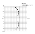
- FIG. 7 and FIG. 8 show the load degree change test results simulating ship speed reduction in waves.
- FIG. 7 is a graph showing the propulsion efficiency when the distance between the front edge of the propeller and the rear end of the duct is changed and when the duct is not provided
- FIG. 8 is the distance between the front edge of the propeller and the rear end of the duct. It is a graph which shows the thrust change at the time of changing.
- the duct 20 has Ddin (the diameter of the front end 21) of 48% of Dp, Ddout (the diameter of the rear end 22) of 40% of Dp, the length (width) W of the duct 20 is 24% of Dp, and the duct blade camber ratio was 8%.
- Ddin the diameter of the front end 21
- Ddout the diameter of the rear end 22
- the length (width) W of the duct 20 is 24% of Dp
- the duct blade camber ratio was 8%.
- the horizontal axis is the ship speed ratio
- the vertical axis is the propulsion efficiency
- the propulsion efficiency when the ship speed ratio is reduced to 0.75 is compared.
- the distance L Dp ⁇ 6% between the front edge of the propeller 10 and the rear end 22 of the duct 20 as Example 1
- L Dp ⁇ 3% as Example 2
- L Dp ⁇ 1% as Example 3
- the propulsion efficiency of Examples 1 to 3 is higher than that of the comparative example in any of the ship speed ratios from 0.75 to 1.
- Example 2 has a greater thrust than Example 1
- Example 3 has a greater thrust than Example 2.
- the thrust increases as the distance L between the front edge of the propeller 10 and the rear end 22 of the duct 20 decreases.
- the duct 20 is combined with the propeller 10 with a decreasing pitch.
- the duct 20 can be reduced in size, and the diameter Ddin of the duct 20 can be set to 20% or more and 50% or less of the diameter Dp of the propeller 10, and the duct 20 can be brought close to the propeller 10 without generating cavitation.
- the pitch H of the propeller 10 is set to a gradually decreasing pitch that decreases in the radial direction, which is the maximum value at the blade root portion of the propeller 10 and the minimum value at the blade tip portion, in a real sea area where the load of the propeller is increased by the wave wind.
- the load distribution in the radius R direction of the propeller 10 that increases the suction effect at the center of the propeller 10 and governs the efficiency can be optimized using the interference with the duct 20.
- the pitch H of the propeller 10 is set to the maximum value at the blade root portion of the propeller 10 and the minimum value at the blade tip portion, cavitation generated at the blade tip portion of the propeller 10 can be suppressed. Generation of vibration and damage to the propeller 10 can be reduced.
- the propeller with a small duct since the duct 20 is 20% or more and 50% or less of the diameter Dp of the propeller 10, the flow velocity of the blade root portion of the propeller 10 is increased, and the propeller 10 at the blade root portion is increased. In combination with the increase in the pitch, the interference can be increased and the efficiency of the propeller 10 can be increased.
- the propeller 10 can be realized that is small and light, has low frictional resistance, low vibration, low noise, and low cost.
- the maximum value Hmax of the pitch H is set to be 120% or more and 160% or less with respect to the minimum value Hmin of the pitch H, thereby suppressing the occurrence of cavitation.
- the suction effect at the center of the propeller 10 can be enhanced to obtain an optimum load distribution, and the propulsion efficiency can be improved.
- the distance L between the rear end 22 of the duct 20 and the front edge of the propeller 10 is 0.5% or more and less than 10% of the diameter Dp of the propeller 10.
- the flow can be accelerated by making the duct 20 an acceleration type duct having an inner diameter on the downstream side smaller than the inner diameter on the upstream side.
- the suction effect can be further enhanced.
- the center of the duct 20 is made coincident with the axis of the propeller 10, so that it can be easily manufactured and installed at low cost.
- the duct 20 is attached to the hull end 1a covering the stern tube 10b or the stern tube 10b of the hull 1 via the support columns 20a, 20b, 20c, 20d. Therefore, the flow can be taken in from the entire front surface, the interference with the propeller 10 can be strengthened to improve the efficiency, and the retrofit of the duct 20 including the existing ship can be easily performed.
- the cross-sectional shape of the duct 20 is the inward convex shape 23, and the protrusion degree of the convex shape 23 is increased on the upstream side of the duct 20 so that the camber ratio is 6%.
- the ratio By setting the ratio to 16% or less, the flow can be accelerated on the upstream side where the average speed is slow, the resistance increase can be suppressed, and the suction effect at the center of the propeller 10 can be further enhanced. In this case, even if the camber ratio is increased to 6% or more and 16% or less due to the suction effect, lift for propelling the hull 1 forward can be increased without causing separation.
- the propeller efficiency can be improved with small size and light weight, low frictional resistance, low vibration, low noise and low cost, and it can be applied to general ships including large ships.
Abstract
本発明の小型ダクト付きプロペラは、船体1の船尾に取り付けるプロペラ10と、プロペラ10の前方に取り付けるダクト20とを有し、ダクト20の直径Ddinをプロペラ10の直径Dpの20%以上50%以下とし、プロペラ10のピッチHを、プロペラの翼根部で最大値となり翼端部で最小値となる、半径R方向に減少する逓減ピッチとしたことを特徴とし、大型ダクトと中型ダクトとの両者の特徴を兼ね備えた省エネ装置として、プロペラ10形状を工夫し、プロペラ10の前方に近接して小型ダクト20を配置することで、荷重度が増加する実海域において、キャビテーションを抑制した上で、効率を支配するプロペラ10の半径R方向の負荷分布を小型ダクト20との干渉を利用して最適化する。
Description
本発明は、船体の船尾に取り付けるプロペラと、プロペラの前方に取り付けるダクトとを有する小型ダクト付きプロペラ、及び小型ダクト付きプロペラを備えた船舶に関する。
従来のプロペラ付近に設けるダクトには、プロペラを覆うタイプのプロペラよりも直径の大きい大型ダクトや、プロペラ直径よりやや小さく、プロペラ前方に配置した中型ダクトがある。
プロペラを覆うタイプの大型ダクトは、ダクトプロペラと呼ばれ、プロペラと一体で荷重度の高い場合に有効な推進器として扱われている。この理由は、プロペラとダクトとの干渉が大きく、この干渉を考慮した性能を推進器として扱う方が合理的だからである。
一方、プロペラ前方のプロペラ直径よりやや小さい中型ダクトは、省エネ装置として扱われ、推進器とは見なされていない。この理由は、ダクトとプロペラの干渉がそれほど大きくなく、むしろ船体とダクトの干渉が大きいからである。
したがって、中型ダクトの性能試験では、船体にダクトを装備したままで抵抗試験を実施する。これはダクトが船体の一部であるという認識に基づく。
プロペラを覆うタイプの大型ダクトは、ダクトプロペラと呼ばれ、プロペラと一体で荷重度の高い場合に有効な推進器として扱われている。この理由は、プロペラとダクトとの干渉が大きく、この干渉を考慮した性能を推進器として扱う方が合理的だからである。
一方、プロペラ前方のプロペラ直径よりやや小さい中型ダクトは、省エネ装置として扱われ、推進器とは見なされていない。この理由は、ダクトとプロペラの干渉がそれほど大きくなく、むしろ船体とダクトの干渉が大きいからである。
したがって、中型ダクトの性能試験では、船体にダクトを装備したままで抵抗試験を実施する。これはダクトが船体の一部であるという認識に基づく。
大型ダクトは、プロペラとの干渉が大きいため、荷重度が増加する実海域において効率が上昇するが、プロペラとダクト間に発生するキャビテーションが問題となり、大型船においては、ほとんど採用されることがない。
中型ダクトについては、特許文献1から特許文献7に示す構成が既に提案されている。
特許文献1では、プロペラ直径よりも小さな直径のダクトが開示され、断面形状が内側に凸形状としたダクトが開示されている。
また、特許文献2では、プロペラ直径と同程度の直径のダクトで大型ダクトの概念にも近いものであり、横方向からみた形状が非軸対称形状のダクトであるが、ダクトの断面形状を内側に凸形状とし、凸形状の突出度を、ダクトの上流側において大きくしたダクトが開示されている。
また、特許文献3では、側面視した形状が非軸対称形状のダクトであるが、ダクト後端部の直径がプロペラ直径の50から80%、ダクト後端面とプロペラ外周先端部との水平距離がプロペラ直径の10から30%とすることが開示されている。
また、特許文献4から特許文献7では、側面視した形状が非軸対称形状のダクトであるが、プロペラ直径よりも小さな直径のダクトが開示されている。
また、特許文献7では、プロペラの翼根部でのピッチをやや大きくし、中央部で減少させ、翼端部で再び増加させた推進装置が開示されている。
しかしながら、プロペラの前方に置かれた中型ダクトは、プロペラとの干渉が弱いため、波風によってプロペラの負荷が増加する実海域において先のダクトプロペラのような効果が、それほど期待できない。
また、各特許文献に開示された中型ダクトは、効率を支配するプロペラの半径方向の負荷分布を小型のダクトとの干渉を利用して最適化するものではない。また、干渉の期待できる大型ダクトは、キャビテーションの問題があり、プロペラ径の大きい大型船には採用が困難である。
また、特許文献7は、プロペラの翼端部でのピッチを大きくしているため、プロペラの翼端部においてキャビテーションが増加してしまう。
また、各特許文献に開示された中型ダクトは、効率を支配するプロペラの半径方向の負荷分布を小型のダクトとの干渉を利用して最適化するものではない。また、干渉の期待できる大型ダクトは、キャビテーションの問題があり、プロペラ径の大きい大型船には採用が困難である。
また、特許文献7は、プロペラの翼端部でのピッチを大きくしているため、プロペラの翼端部においてキャビテーションが増加してしまう。
そこで、本発明は、大型ダクトと中型ダクトとの両者の特徴を兼ね備えた省エネ装置として、プロペラ形状を工夫し、プロペラの前方に近接して小型のダクトを配置することで、荷重度が増加する実海域において、キャビテーションを抑制した上で、効率を支配するプロペラの半径方向の負荷分布を小型のダクトとの干渉を利用して最適化することを目的とする。
請求項1記載に対応した小型ダクト付きプロペラにおいては、船体の船尾に取り付けるプロペラと、プロペラの前方に取り付けるダクトとを有する小型ダクト付きプロペラにおいて、ダクトの直径をプロペラの直径の20%以上50%以下とし、プロペラのピッチを、プロペラの翼根部で最大値となり翼端部で最小値となる、半径方向に減少する逓減ピッチとしたことを特徴とする。請求項1に記載の本発明によれば、ダクトを逓減ピッチのプロペラと組み合わせ、ダクトの直径をプロペラの直径の20%以上50%以下とすることでキャビテーションを発生させずにダクトをプロペラに近づけることができ、プロペラのピッチを逓減ピッチとすることで、波風によってプロペラの荷重度が増加する実海域において、プロペラ中心部での吸い込み効果を高め、効率を支配するプロペラの半径方向の負荷分布をダクトとの干渉を利用して最適化することができる。また、プロペラピッチを、プロペラの翼根部で最大値とし、翼端部で最小値とすることにより、プロペラ翼端部で発生するキャビテーションを抑制できる。また、請求項1に記載の本発明によれば、プロペラの直径の20%以上50%以下のダクトであるため、小型軽量で摩擦抵抗が小さく、低振動、低騒音、低コストでプロペラの効率を高めることができる。
請求項2記載の本発明は、請求項1に記載の小型ダクト付きプロペラにおいて、ピッチの最大値を、ピッチの最小値に対して120%以上160%以下としたことを特徴とする。請求項2に記載の本発明によれば、プロペラ中心部での吸い込み効果を高めて最適な負荷分布とすることができる。
請求項3記載の本発明は、請求項1又は請求項2に記載の小型ダクト付きプロペラにおいて、ダクトの後端とプロペラの前縁との距離を、プロペラの直径の0.5%以上10%未満としたことを特徴とする。請求項3に記載の本発明によれば、逓減ピッチのプロペラの吸い込み効果により剥離を生じることなくダクトをプロペラに近接させることができ、ダクトとプロペラとの干渉効果を高めることができる。
請求項4記載の本発明は、請求項1から請求項3に記載の小型ダクト付きプロペラにおいて、ダクトの断面形状を内側に凸形状とし、凸形状の突出度を、ダクトの上流側において大きくしてキャンバー比を6%以上16%以下としたことを特徴とする。請求項4に記載の本発明によれば、キャンバー比を6%以上16%以下としても、プロペラ中心部での吸い込み効果により、剥離を生じさせることなく、分力として船体を前方に推進する揚力を増加させることができる。
請求項5記載の本発明は、請求項1から請求項4に記載の小型ダクト付きプロペラにおいて、ダクトを、上流側の内直径よりも下流側の内直径が小さい加速型ダクトとしたことを特徴とする。請求項5に記載の本発明によれば、プロペラ中心部での吸い込み効果と、分力として船体を前方に推進する揚力とを更に高めることができる。
請求項6記載の本発明は、請求項1から請求項5に記載の小型ダクト付きプロペラにおいて、ダクトの中心をプロペラの軸心と一致させたことを特徴とする。請求項6に記載の本発明によれば、非軸対称形のダクトやプロペラ軸とダクトの中心軸をずらしたり、傾斜角を持たせて設置するダクトと比較して、製作や設置が容易で安価に提供できる。
請求項7記載の本発明は、請求項1から請求項6に記載の小型ダクト付きプロペラにおいて、ダクトが支柱を介して船体の船尾管又は船尾管を覆う船体端部に取り付けられたことを特徴とする。請求項7に記載の本発明によれば、流れを前方の全面から取り込み、プロペラとの干渉を強めて効率向上を図れるとともに、ダクトの後付を容易に行うことができる。
請求項8記載の本発明は、請求項1から請求項7に記載の小型ダクト付きプロペラにおいて、ダクトの内面に、プロペラへの流れを対向流化する固定翼を有したことを特徴とする。請求項8に記載の本発明によれば、ダクトに流入した流れは固定翼によってプロペラに対向流として流入することにより、プロペラ効率の一層の向上が図れる。
請求項9記載の本発明は、請求項8に記載の小型ダクト付きプロペラにおいて、支柱が固定翼を兼ね、支柱がプロペラの回転方向と逆方向に捻られていることを特徴とする。請求項9に記載の本発明によれば、支柱により回転流化することにより支柱が固定翼を兼ねることができ、構成が簡素化される。
請求項10記載に対応した船舶においては、請求項1から請求項9のいずれかに記載の小型ダクト付きプロペラを装備したことを特徴とする。請求項10に記載の本発明によれば、荷重度が増加する実海域においてプロペラ効率の高い船舶を提供することができる。
本発明の小型ダクト付きプロペラによれば、ダクトを逓減ピッチのプロペラと組み合わせることによりダクトの小型化が図れ、ダクトの直径をプロペラの直径の20%以上50%以下とすることでキャビテーションを発生させずにダクトをプロペラに近づけることができる。従って、プロペラのピッチを逓減ピッチとすることで、波風によってプロペラの荷重度が増加する実海域において、プロペラ中心部での吸い込み効果を高め、効率を支配するプロペラの半径方向の負荷分布をダクトとの干渉を利用して最適化することができる。また、プロペラピッチをプロペラの翼根部で最大値とし翼端部で最小値とすることにより、プロペラ翼端部で発生するキャビテーションを抑制できる。
また、本発明の小型ダクト付きプロペラによれば、プロペラの直径の20%以上50%以下のダクトであるため、小型軽量で摩擦抵抗が小さく、低振動、低騒音、低コストでプロペラの効率を高めることができる。
また、ピッチの最大値を、ピッチの最小値に対して120%以上160%以下とした場合には、プロペラ中心部での吸い込み効果を高めて、最適な負荷分布とすることができる。
また、ダクトの後端とプロペラの前縁との距離を、プロペラの直径の0.5%以上10%未満とした場合には、逓減ピッチのプロペラの吸い込み効果により剥離を生じることなくダクトをプロペラに近接させることができ、ダクトとプロペラとの干渉効果を高めることができる。
また、ダクトの断面形状を内側に凸形状とし、凸形状の突出度を、ダクトの上流側において大きくしてキャンバー比を6%以上16%以下とした場合には、キャンバー比を6%以上16%以下としてもプロペラ中心部での吸い込み効果により、剥離を生じることなく、分力として船体を前方に推進する揚力を増加させることができる。
また、ダクトを、上流側の内直径よりも下流側の内直径が小さい加速型ダクトとした場合には、プロペラ中心部での吸い込み効果と、分力として船体を前方に推進する揚力とを更に高めることができる。
また、ダクトの中心をプロペラの軸心と一致させた場合には、非軸対称形のダクトやプロペラ軸とダクトの中心軸をずらしたり、傾斜角を持たせて設置するダクトと比較して、製作や設置が容易で安価に提供できる。
また、ダクトが支柱を介して船体の船尾管又は船尾管を覆う船体端部に取り付けられた場合には、流れを前方の全面から取り込み、プロペラとの干渉を強めて効率向上を図れるとともに、ダクトの後付を容易に行うことができる。
また、ダクトの内面に、プロペラへの流れを対向流化する固定翼を有した場合には、ダクトに流入した流れは固定翼によってプロペラに対向流として流入することにより、プロペラ効率の一層の向上が図れる。
また、支柱が固定翼を兼ね、支柱がプロペラの回転方向と逆方向に捻られている場合には、支柱により回転流化することにより支柱が固定翼を兼ねることができ、構成が簡素化される。
本発明の船舶によれば、特に荷重度が増加する実海域においてプロペラ効率の高い船舶を提供することができる。
1 船体
1a 船体端部
10 プロペラ
10b 船尾管
11 ボス
20 ダクト
20a、20b、20c、20d 支柱(固定翼)
Dp プロペラの直径
Ddin ダクトの前端の直径
Ddout ダクトの後端の直径
H ピッチ
L ダクトの後端とプロペラの前縁との距離
1a 船体端部
10 プロペラ
10b 船尾管
11 ボス
20 ダクト
20a、20b、20c、20d 支柱(固定翼)
Dp プロペラの直径
Ddin ダクトの前端の直径
Ddout ダクトの後端の直径
H ピッチ
L ダクトの後端とプロペラの前縁との距離
以下に、本発明の実施形態による小型ダクト付きプロペラについて説明する。
図1は本発明の実施形態による小型ダクト付きプロペラを装備した船舶の概略構成図、図2(a)は同船舶に用いる小型ダクト付きプロペラの要部を示す一部断面側面図、図2(b)は同図(a)のA-A断面図、図3は同船舶に用いる他の小型ダクト付きプロペラの要部を示す一部断面構成図、図4は同逓減ピッチプロペラと通常プロペラのピッチ分布を示すグラフ、図5は同逓減ピッチプロペラと通常プロペラの流速分布を示すグラフ、図6は同小型ダクト付きプロペラにおけるダクトの後端とプロペラの前縁との距離による流速分布を示すグラフである。
図1は本発明の実施形態による小型ダクト付きプロペラを装備した船舶の概略構成図、図2(a)は同船舶に用いる小型ダクト付きプロペラの要部を示す一部断面側面図、図2(b)は同図(a)のA-A断面図、図3は同船舶に用いる他の小型ダクト付きプロペラの要部を示す一部断面構成図、図4は同逓減ピッチプロペラと通常プロペラのピッチ分布を示すグラフ、図5は同逓減ピッチプロペラと通常プロペラの流速分布を示すグラフ、図6は同小型ダクト付きプロペラにおけるダクトの後端とプロペラの前縁との距離による流速分布を示すグラフである。
図1に示すように、船舶は、船体1の船尾に取り付けるプロペラ10と、プロペラ10の前方に取り付けるダクト20とを有している。
図2(a)に示すように、プロペラ10は中心部にボス11を有し、ダクト20は、上流側となる前端21の内直径よりも下流側となる後端22の内直径が小さい加速型ダクトである。
ダクト20は、その断面形状が内側に凸形状23となっており、凸形状23の突出度は、ダクト20の上流側において大きくしている。最大キャンバー位置におけるキャンバー比は、6%以上16%以下としている。一般にはキャンバー比が8%を越えるとダクト20内で剥離を生じるが、本実施の形態で特定した小型のダクト20をプロペラ10の前方に近接させて設け、プロペラ10のピッチを半径方向に減少する逓減ピッチとしているため、プロペラ10中心部での吸い込み効果により8%を越えても剥離を生じることなく揚力を増加させることができる。このようにダクト20を加速型ダクトとし、断面形状を内側に凸形状としてキャンバー比を高くすることにより、流れが加速でき、プロペラ10との干渉を高めることができ,、分力として船体1を前方に推進する揚力も増すことができる。
ダクト20は、その断面形状が内側に凸形状23となっており、凸形状23の突出度は、ダクト20の上流側において大きくしている。最大キャンバー位置におけるキャンバー比は、6%以上16%以下としている。一般にはキャンバー比が8%を越えるとダクト20内で剥離を生じるが、本実施の形態で特定した小型のダクト20をプロペラ10の前方に近接させて設け、プロペラ10のピッチを半径方向に減少する逓減ピッチとしているため、プロペラ10中心部での吸い込み効果により8%を越えても剥離を生じることなく揚力を増加させることができる。このようにダクト20を加速型ダクトとし、断面形状を内側に凸形状としてキャンバー比を高くすることにより、流れが加速でき、プロペラ10との干渉を高めることができ,、分力として船体1を前方に推進する揚力も増すことができる。
プロペラ10の直径をDp、ダクト20の前端21の直径をDdin、ダクト20の後端22の直径をDdout、プロペラ10の前縁とダクト20の後端22との距離をLとすると、ダクト20の前端21の直径Ddinをプロペラ10の直径Dpの50%以下、ダクト20の後端22とプロペラ10の前縁との距離Lをプロペラ10の直径Dpの15%以下、更には10%未満とすることが好ましい。ダクト20の後端22とプロペラ10の前縁との距離Lは、可能な限り近接させることが好ましいが、ダクト20とプロペラ10との接触を避けるためには、プロペラ10の直径Dpの0.5%以上とすることが好ましい。
ダクト20の前端21の直径Ddin、及びダクト20の後端22の直径Ddoutは、プロペラ10の直径Dpに対して20%以上50%以下とする。プロペラ10の直径Dpに対して20%以上50%以下の範囲において、ダクト20の前端21の直径Ddinとダクト20の後端22の直径Ddoutが等しい筒状であってもよい。ダクト20の前端21の直径Ddinとダクト20の後端22の直径Ddoutは、Ddin>Ddoutとすることがより好ましい。また、ダクト20の前端21の直径Ddinは、プロペラ10の直径Dpに対して35%以上50%以下、ダクト20の後端22の直径Ddoutは、プロペラ10の直径Dpに対して20%以上40%未満とすることがより好ましい。
プロペラ10の直径Dpの20%以上50%以下のダクト20とすることで、小型軽量で摩擦抵抗が小さく、低振動、低騒音、低コストでプロペラ10の効率を高めることができる。
また、ダクト20の幅W(長さ)は、干渉効果を高め、また船尾部への当接や抵抗増加を避けるため、直径Dpに対して20%以上60%以下であることが好ましい。特に、大型船を含めて広く一般の船舶に適用する上では、ダクト20の幅Wは、直径Dpに対して25%以上50%以下であることがより好ましい。
プロペラ10の直径Dpの20%以上50%以下のダクト20とすることで、小型軽量で摩擦抵抗が小さく、低振動、低騒音、低コストでプロペラ10の効率を高めることができる。
また、ダクト20の幅W(長さ)は、干渉効果を高め、また船尾部への当接や抵抗増加を避けるため、直径Dpに対して20%以上60%以下であることが好ましい。特に、大型船を含めて広く一般の船舶に適用する上では、ダクト20の幅Wは、直径Dpに対して25%以上50%以下であることがより好ましい。
図2(a)に示すように、ダクト20は軸対称形に形成され、プロペラ10の駆動軸10aとダクト20の中心軸を一致させて取り付けているため、非軸対称形のダクトやプロペラ軸とダクトの中心軸をずらしたり、傾斜角を持たせて設置するダクトと比較し、製作や設置が容易で安価に提供できるものとなっている。
図2(b)に示すように、ダクト20は支柱20a、20b、20c、20dによって船尾管10bを覆う船体端部1aに取り付けられている。船尾管10bはプロペラ10の駆動軸10a周りに設けられている。なお、船尾管10bを露出している形式の船舶にあっては、ダクト20は支柱20a、20b、20c、20dにより船尾管10bに直接取り付けてもよい。また、船尾管10bを一部露出している船舶にあっては、ダクト20は、支柱20a、20b、20c、20dにより、船尾管10bと船体端部1aの双方に取り付けてもよい。
ダクト20を、支柱20a、20b、20c、20dを介して船体1の船尾管10b又は船尾管10bを覆う船体端部1aに取り付けることで、流れを前方の全面から取り込み、プロペラ10との干渉を強めて効率向上を図れるとともに、ダクト20の後付けを容易に行うことができる。これは既存船に後付でダクト20を取り付ける場合に利点が大きいが、新造船に取り付ける場合も、従来のように船体1の外板へ加工を要しないため利点を有している。
ダクト20を、支柱20a、20b、20c、20dを介して船体1の船尾管10b又は船尾管10bを覆う船体端部1aに取り付けることで、流れを前方の全面から取り込み、プロペラ10との干渉を強めて効率向上を図れるとともに、ダクト20の後付けを容易に行うことができる。これは既存船に後付でダクト20を取り付ける場合に利点が大きいが、新造船に取り付ける場合も、従来のように船体1の外板へ加工を要しないため利点を有している。
支柱20a、20b、20c、20dは、ダクト20の中心軸に対して放射状に配置し、特に支柱20aと支柱20dとの間の角度を、支柱20bと支柱20cとの間の角度よりも小さくすることで、伴流分布を改善できる。
支柱は最低2本、最大5本とすることが好ましく、ダクト20の外側に更に支柱を設けることも可能である。
支柱は最低2本、最大5本とすることが好ましく、ダクト20の外側に更に支柱を設けることも可能である。
また、ダクト20の流路断面は、前端21の直径Ddinより後端22の直径Ddoutが狭まるように構成している。ダクト20の流路断面を、下流に向かって狭めることで伴流分布を改善できる。ダクト20の下流側の流路断面を狭めるために、ダクト20の内断面を小さくする他に、支柱20a、20b、20c、20dの断面積を下流側に向かって大きくしてもよい。伴流分布を改善することで、小型のダクト20によるプロペラ効率をさらに向上できる。
図3に示すように、ダクト20の内面に捻りを有した支柱20eを設け、プロペラ10への流れを対向流(カウンターフロー)化することもできる。この場合、その船体中心線に対する取り付け角度は、船体側θsで5度から25度、ダクト20の内面側θdで5度から10度とすることが好ましい。ダクト20に流入した流れは、上流側から下流側に向かって加速されるとともに、捻りを有した支柱20eによりプロペラ10の回転方向と逆向きに回転流化され、プロペラ10に対向流として流入することにより、プロペラ効率の一層の向上が図れる。
なお、支柱20eはダクト20の外側に設け、ダクト20の内面には流れを回転流化する固定翼を専用に設けてもよいが、支柱20eにより回転流化することにより支柱20eが固定翼を兼ねることができ、構成が簡素化される。
なお、支柱20eはダクト20の外側に設け、ダクト20の内面には流れを回転流化する固定翼を専用に設けてもよいが、支柱20eにより回転流化することにより支柱20eが固定翼を兼ねることができ、構成が簡素化される。
図4に同逓減ピッチプロペラと通常プロペラのピッチ分布を示す。
プロペラ10は、ボス11の半径をr1、翼根部を半径r1から半径r2とする。半径Rは1/2Dpであり、Hはピッチである。翼根部は、プロペラ10の直径Dpの20%以上40%以下である。
本実施の形態によるプロペラ10のピッチHは、プロペラ10の翼根部で最大値となり翼端部で最小値となる、半径R方向に減少する逓減ピッチとしている。図4に示す比較例は一定ピッチを示している。
本実施の形態によるプロペラ10のピッチHは、プロペラ10の翼根部(r1からr2)で最大値Hmaxとなり、最大値Hmaxを、ピッチHの最小値Hminに対して推進効率とキャビテーション発生抑制を考慮して120%以上160%以下としている。
図5は、図4に示す本実施の形態による逓減ピッチによるプロペラと、比較例としての通常プロペラとの流速分布を示している。
Vはプロペラ10の流入側の流速、Vxはプロペラ10の流出側の流速で、V及びVxはいずれも軸方向の流速である。
図5に示すように、本実施の形態では比較例に対して、r1/Rが0.2から0.6において流速分布が向上している。
すなわち図5では、プロペラ10を逓減ピッチとすることにより、プロペラ10の中心付近(翼根部)の流速分布が改善されるため、ダクト20が直径Ddinの小さい小型のダクト20であってもよいことを示唆している。ダクト20を小型化できることにより、プロペラ10の翼根部の流速を増加させ、翼根部におけるプロペラ10のピッチの増加と相まって干渉を高めることができる。また、軽量で低コストでの製作が可能となり、表面積が小さいことから摩擦抵抗の低減にも繋がる。また、小型のダクト20であることにより、相対的に速度の遅いプロペラ10の翼根部の流速を高めるため、キャビテーションの発生を抑制でき、プロペラ10の損傷や振動、騒音の発生が防止できる。さらに、プロペラ10のピッチが、翼根部で最大値となり翼端部で最小値となる半径方向に減少する逓減ピッチであるため、
プロペラ10の翼端部で発生するキャビテーションも抑制できる。
図6は、同小型ダクト付きプロペラにおけるダクト20の後端22とプロペラ10の前縁との距離Lを変更した場合の流速分布を示している。
距離Lは、プロペラ10の直径Dpの15%以下において、プロペラ10とダクト20との干渉が顕著に表れており、距離LをDpの10%未満とすることで更にプロペラ10の半径R方向の負荷分布に大きな影響を与えている。また、距離Lを長くしすぎると船体1に当接してしまう。距離LをDpの10%未満とすることで、船体1に当接することを防止し、前方の全面から流れを取り込むことが困難になることを防止できる。
距離Lは、プロペラ10の直径Dpの15%以下において、プロペラ10とダクト20との干渉が顕著に表れており、距離LをDpの10%未満とすることで更にプロペラ10の半径R方向の負荷分布に大きな影響を与えている。また、距離Lを長くしすぎると船体1に当接してしまう。距離LをDpの10%未満とすることで、船体1に当接することを防止し、前方の全面から流れを取り込むことが困難になることを防止できる。
図7及び図8に波浪中における船速低下を模擬した荷重度変更試験結果を示す。
図7は、プロペラの前縁とダクトの後端との距離を変化させた場合とダクトを設けない場合の推進効率を示すグラフ、図8は、プロペラの前縁とダクトの後端との距離を変化させた場合の推力変化を示すグラフである。
図7は、プロペラの前縁とダクトの後端との距離を変化させた場合とダクトを設けない場合の推進効率を示すグラフ、図8は、プロペラの前縁とダクトの後端との距離を変化させた場合の推力変化を示すグラフである。
本実験では、Lpp(垂線間長さ)=229m、B(船の幅)=42m、D(船の深さ)=12.19mのアフラマックスタンカーを試験対象船とし、Lpp=4.8600m、B=0.8914m、D=0.2587mのモデル船を用いた。
また、試験対象船のプロペラ10は、Dp(プロペラ直径)=7m、H/D(0.7R)(ピッチ位置)=0.67、EAR(展開面積比)=0.45、Rake(翼傾斜)=-216.7mm、Z(翼数)=4、Boss Ratio(ボス比)=0.1586、Skew(翼の反り)=20degとし、Dp=0.148559m、H/D(0.7R)=0.67、EAR=0.45、Rake=-4.6mm、Z=4、Boss Ratio=0.1586、Skew=20degをモデルプロペラとして用いた。
また、試験対象船のプロペラ10は、Dp(プロペラ直径)=7m、H/D(0.7R)(ピッチ位置)=0.67、EAR(展開面積比)=0.45、Rake(翼傾斜)=-216.7mm、Z(翼数)=4、Boss Ratio(ボス比)=0.1586、Skew(翼の反り)=20degとし、Dp=0.148559m、H/D(0.7R)=0.67、EAR=0.45、Rake=-4.6mm、Z=4、Boss Ratio=0.1586、Skew=20degをモデルプロペラとして用いた。
ダクト20は、Ddin(前端21の直径)がDpの48%、Ddout(後端22の直径)がDpの40%、ダクト20の長さ(幅)WをDpの24%、ダクト翼キャンバー比を8%とした。
本実験は、波浪中における船速低下を模擬するため、回転数一定のまま船速を低下させ、プロペラ荷重度を増加させた状態での自航試験を行った。
本実験は、波浪中における船速低下を模擬するため、回転数一定のまま船速を低下させ、プロペラ荷重度を増加させた状態での自航試験を行った。
図7では、横軸を船速比、縦軸を推進効率とし、船速比を0.75まで低下させた場合の推進効率を比較している。
実施例1としてプロペラ10の前縁とダクト20の後端22との距離L=Dp×6%、実施例2としてL=Dp×3%、実施例3としてL=Dp×1%を用い、ダクト20を用いないものを比較例として示している。
実施例1から実施例3は、船速比0.75から1までのいずれにおいても比較例よりも推進効率が上回っている。
実施例1としてプロペラ10の前縁とダクト20の後端22との距離L=Dp×6%、実施例2としてL=Dp×3%、実施例3としてL=Dp×1%を用い、ダクト20を用いないものを比較例として示している。
実施例1から実施例3は、船速比0.75から1までのいずれにおいても比較例よりも推進効率が上回っている。
図8では、横軸をプロペラ推力、縦軸をダクト抵抗(推力)とし、プロペラ推力を1.05から1.3の間で変化させた場合の推力を比較している。
実施例2は実施例1よりも推力が増加し、実施例3は実施例2よりも推力が増加している。
図8に示すように、プロペラ10の前縁とダクト20の後端22との距離Lは小さいほど推力が増加する。
実施例2は実施例1よりも推力が増加し、実施例3は実施例2よりも推力が増加している。
図8に示すように、プロペラ10の前縁とダクト20の後端22との距離Lは小さいほど推力が増加する。
本実施の形態による小型ダクト付きプロペラによれば、船体1の船尾に取り付けるプロペラ10と、プロペラ10の前方に取り付けるダクト20とを有する小型ダクト付きプロペラにおいて、ダクト20を逓減ピッチのプロペラ10と組み合わせたことで、ダクト20の小型化が可能となり、ダクト20の直径Ddinをプロペラ10の直径Dpの20%以上50%以下としキャビテーションを発生させずにダクト20をプロペラ10に近づけることができる。従って、プロペラ10のピッチHをプロペラ10の翼根部で最大値となり翼端部で最小値となる、半径方向に減少する逓減ピッチとすることで、波風によってプロペラの荷重度が増加する実海域において、プロペラ10中心部での吸い込み効果を高め、効率を支配するプロペラ10の半径R方向の負荷分布をダクト20との干渉を利用して最適化することができる。また、プロペラ10のピッチHをプロペラ10の翼根部で最大値とし翼端部で最小値とすることにより、プロペラ10の翼端部で発生するキャビテーションを抑制できるため、推進効率の低下や騒音、振動の発生、またプロペラ10の損傷を低減できる。
また、本実施の形態による小型ダクト付きプロペラによれば、プロペラ10の直径Dpの20%以上50%以下のダクト20であるため、プロペラ10の翼根部の流速を増加させ、翼根部におけるプロペラ10のピッチの増加と相まって干渉を高めプロペラ10の効率を高めることができる。また、小型軽量で摩擦抵抗が小さく、低振動、低騒音、低コストのプロペラ10を実現することができる。
また、本実施の形態による小型ダクト付きプロペラによれば、ピッチHの最大値Hmaxを、ピッチHの最小値Hminに対して120%以上160%以下としたことで、キャビテーションの発生を抑制した上で、プロペラ10中心部での吸い込み効果を高めて最適な負荷分布とし、推進効率を向上することができる。
また、本実施の形態による小型ダクト付きプロペラによれば、ダクト20の後端22とプロペラ10の前縁との距離Lを、プロペラ10の直径Dpの0.5%以上10%未満としたことで、ダクト前端21が船尾部の船体1に触れることを防止しダクト20の前方の全面から流れを取り込み、ダクト20とプロペラ10との干渉効果を高めることができる。
また、本実施の形態による小型ダクト付きプロペラによれば、ダクト20を、上流側の内直径よりも下流側の内直径が小さい加速型ダクトとしたことで流れが加速でき、プロペラ10中心部での吸い込み効果を更に高めることができる。
また、本実施の形態による小型ダクト付きプロペラによれば、ダクト20の中心をプロペラ10の軸心と一致させたことで、製作や設置が容易で安価に提供できる。
また、本実施の形態による小型ダクト付きプロペラによれば、ダクト20が支柱20a、20b、20c、20dを介して船体1の船尾管10b又は船尾管10bを覆う船体端部1aに取り付けられているため、流れを前方の全面から取り込み、プロペラ10との干渉を強めて効率向上を図れるとともに、既存船を含めてダクト20の後付を容易に行うことができる。
また、本実施の形態による小型ダクト付きプロペラによれば、ダクト20の断面形状を内側に凸形状23とし、凸形状23の突出度を、ダクト20の上流側において大きくしてキャンバー比を6%以上16%以下としたことで平均速度の遅い上流側で流れが加速でき、抵抗増加を抑え、プロペラ10中心部での吸い込み効果を更に高めることができる。この場合、吸い込み効果によりキャンバー比を6%以上16%以下と高くしても剥離を生じることなく、船体1を前方に推進する揚力を増加させることができる。
また、本実施の形態による小型ダクト付きプロペラを装備することで、荷重度が増加する実海域においてプロペラ効率の高い船舶を提供することができる。
本発明の小型ダクト付きプロペラによれば、小型軽量で摩擦抵抗が小さく、低振動、低騒音、低コストでプロペラの効率を高めることができ、大型船を含めて広く一般の船舶に適用できる。
Claims (10)
- 船体の船尾に取り付けるプロペラと、前記プロペラの前方に取り付けるダクトとを有する小型ダクト付きプロペラにおいて、
前記ダクトの直径を前記プロペラの直径の20%以上50%以下とし、
前記プロペラのピッチを、前記プロペラの翼根部で最大値となり翼端部で最小値となる、半径方向に減少する逓減ピッチとしたことを特徴とする小型ダクト付きプロペラ。 - 前記ピッチの前記最大値を、前記ピッチの最小値に対して120%以上160%以下としたことを特徴とする請求項1に記載の小型ダクト付きプロペラ。
- 前記ダクトの後端と前記プロペラの前縁との距離を、前記プロペラの直径の0.5%以上10%未満としたことを特徴とする請求項1又は請求項2に記載の小型ダクト付きプロペラ。
- 前記ダクトの断面形状を内側に凸形状とし、前記凸形状の突出度を、前記ダクトの上流側において大きくしてキャンバー比を6%以上16%以下としたことを特徴とする請求項1から請求項3のいずれかに記載の小型ダクト付きプロペラ。
- 前記ダクトを、上流側の内直径よりも下流側の内直径が小さい加速型ダクトとしたことを特徴とする請求項1から請求項4のいずれかに記載の小型ダクト付きプロペラ。
- 前記ダクトの中心を前記プロペラの軸心と一致させたことを特徴とする請求項1から請求項5のいずれかに記載の小型ダクト付きプロペラ。
- 前記ダクトが支柱を介して前記船体の船尾管又は前記船尾管を覆う船体端部に取り付けられたことを特徴とする請求項1から請求項6のいずれかに記載の小型ダクト付きプロペラ。
- 前記ダクトの内面に、前記プロペラへの流れを対向流化する固定翼を有したことを特徴とする請求項1から請求項7のいずれかに記載の小型ダクト付きプロペラ。
- 前記支柱が前記固定翼を兼ね、前記支柱が前記プロペラの回転方向と逆方向に捻られていることを特徴とする請求項8に記載の小型ダクト付きプロペラ。
- 請求項1から請求項9のいずれかに記載の小型ダクト付きプロペラを装備したことを特徴とする船舶。
Priority Applications (7)
| Application Number | Priority Date | Filing Date | Title |
|---|---|---|---|
| CN201280037120.8A CN103717488B (zh) | 2011-07-26 | 2012-07-26 | 带小型导管的螺旋桨和船舶 |
| EP12817040.4A EP2738084B1 (en) | 2011-07-26 | 2012-07-26 | Propeller with small duct, and ship |
| EP18215036.7A EP3495257B1 (en) | 2011-07-26 | 2012-07-26 | Propeller setting small duct, and ship |
| KR1020197030835A KR102144840B1 (ko) | 2011-07-26 | 2012-07-26 | 소형 덕트가 달린 프로펠러 및 선박 |
| KR1020187022009A KR102037018B1 (ko) | 2011-07-26 | 2012-07-26 | 소형 덕트가 달린 프로펠러 및 선박 |
| KR1020147004953A KR101917408B1 (ko) | 2011-07-26 | 2012-07-26 | 소형 덕트가 달린 프로펠러 및 선박 |
| JP2012554146A JP5230852B1 (ja) | 2011-07-26 | 2012-07-26 | 小型ダクト付きプロペラ及び船舶 |
Applications Claiming Priority (2)
| Application Number | Priority Date | Filing Date | Title |
|---|---|---|---|
| JP2011-163203 | 2011-07-26 | ||
| JP2011163203 | 2011-07-26 |
Publications (1)
| Publication Number | Publication Date |
|---|---|
| WO2013014938A1 true WO2013014938A1 (ja) | 2013-01-31 |
Family
ID=47600800
Family Applications (1)
| Application Number | Title | Priority Date | Filing Date |
|---|---|---|---|
| PCT/JP2012/004777 WO2013014938A1 (ja) | 2011-07-26 | 2012-07-26 | 小型ダクト付きプロペラ及び船舶 |
Country Status (5)
| Country | Link |
|---|---|
| EP (2) | EP2738084B1 (ja) |
| JP (1) | JP5230852B1 (ja) |
| KR (3) | KR101917408B1 (ja) |
| CN (2) | CN103717488B (ja) |
| WO (1) | WO2013014938A1 (ja) |
Cited By (4)
| Publication number | Priority date | Publication date | Assignee | Title |
|---|---|---|---|---|
| WO2014115567A1 (ja) * | 2013-01-25 | 2014-07-31 | 独立行政法人海上技術安全研究所 | 小型ダクト付き船舶及び船舶への小型ダクト適用判断方法 |
| JP2015116850A (ja) * | 2013-12-16 | 2015-06-25 | 国立研究開発法人海上技術安全研究所 | 船尾用ダクト、船尾用ダクトの設計方法、及び船尾用ダクトを装備した船舶 |
| CN104828225A (zh) * | 2015-05-14 | 2015-08-12 | 广西梧州运龙港船机械制造有限公司 | 船用螺旋桨 |
| CN115140282A (zh) * | 2022-05-31 | 2022-10-04 | 中国船舶重工集团公司第七一九研究所 | 抗空化推进器及推进系统 |
Families Citing this family (6)
| Publication number | Priority date | Publication date | Assignee | Title |
|---|---|---|---|---|
| CN103717488B (zh) * | 2011-07-26 | 2016-10-26 | 国立研究开发法人海上·港湾·航空技术研究所 | 带小型导管的螺旋桨和船舶 |
| CN104787284A (zh) * | 2015-04-08 | 2015-07-22 | 浙江海洋学院 | 子母共轴导管轮螺旋桨 |
| KR102065866B1 (ko) * | 2016-03-14 | 2020-02-11 | 재팬 마린 유나이티드 코포레이션 | 양력 발생체 |
| JP6827034B2 (ja) * | 2016-03-29 | 2021-02-10 | ジャパンマリンユナイテッド株式会社 | 船舶の推進装置 |
| KR101894019B1 (ko) * | 2017-01-12 | 2018-09-03 | 성동조선해양 주식회사 | 환형 구조물을 포함하는 전류고정날개 |
| CN112078770B (zh) * | 2019-11-14 | 2021-08-03 | 浙江大学 | 一种全导管式双级吊舱推进器及其设计方法 |
Citations (8)
| Publication number | Priority date | Publication date | Assignee | Title |
|---|---|---|---|---|
| JPS5632396A (en) | 1979-08-17 | 1981-04-01 | Toshiba Ceramics Co Ltd | Silicon single crystal pulling apparatus |
| JPH0317996U (ja) | 1989-02-27 | 1991-02-21 | ||
| JPH082486A (ja) * | 1994-04-19 | 1996-01-09 | Mitsui Eng & Shipbuild Co Ltd | 船 舶 |
| JPH09175488A (ja) | 1995-12-22 | 1997-07-08 | Sumitomo Heavy Ind Ltd | 船尾ダクト付き船舶 |
| JPH10264890A (ja) | 1997-03-28 | 1998-10-06 | Hitachi Zosen Corp | 船舶における推進装置 |
| JP2002220089A (ja) | 2001-01-23 | 2002-08-06 | Hitachi Zosen Corp | 船舶の推進効率向上用ダクト |
| JP2007331549A (ja) | 2006-06-14 | 2007-12-27 | Universal Shipbuilding Corp | 船尾ダクト及びそれを取り付けた船舶 |
| JP2008143488A (ja) | 2006-12-13 | 2008-06-26 | Universal Shipbuilding Corp | 船舶用ダクトおよび船舶用ダクト付き船舶 |
Family Cites Families (16)
| Publication number | Priority date | Publication date | Assignee | Title |
|---|---|---|---|---|
| JPS5939438Y2 (ja) | 1979-08-20 | 1984-11-02 | 日本電気ホームエレクトロニクス株式会社 | 高周波加熱装置 |
| JPS56147195U (ja) * | 1980-04-04 | 1981-11-06 | ||
| JPH0220180Y2 (ja) | 1985-06-10 | 1990-06-01 | ||
| JPH069999B2 (ja) * | 1985-08-20 | 1994-02-09 | 三菱重工業株式会社 | 舶用可変ピツチプロペラ |
| JPS63264890A (ja) | 1987-04-22 | 1988-11-01 | Mitsubishi Electric Corp | 誘導加熱装置の冷却装置 |
| US4802822A (en) * | 1987-10-08 | 1989-02-07 | Brunswick Corporation | Marine propeller with optimized performance blade contour |
| JPH0220180A (ja) | 1988-07-08 | 1990-01-23 | Matsushita Electric Ind Co Ltd | 磁気記録再生装置 |
| US5752865A (en) * | 1995-04-11 | 1998-05-19 | Mitsui Engineering & Shipbuilding Co., Ltd. | Ship |
| JP3491890B2 (ja) * | 2000-09-28 | 2004-01-26 | 株式会社 商船三井 | ハブ渦消去装置を有する船舶のプロペラ |
| JP2005112257A (ja) * | 2003-10-10 | 2005-04-28 | Shin Kurushima Dockyard Co Ltd | プロペラ |
| KR101046088B1 (ko) * | 2007-10-26 | 2011-07-01 | 유니버설 조센 가부시키가이샤 | 선미 덕트 및 그것을 부착한 선박 |
| DE202009002642U1 (de) | 2008-03-10 | 2009-06-25 | Becker Marine Systems Gmbh & Co. Kg | Vorrichtung zur Verringerung des Antriebsleistungsbedarfes eines Schiffes |
| JP2010095181A (ja) * | 2008-10-17 | 2010-04-30 | Ihi Corp | 船舶の推進装置 |
| JP2011025734A (ja) * | 2009-07-22 | 2011-02-10 | Universal Shipbuilding Corp | 舶用複合型省エネ推進装置及び一軸二舵船舶 |
| KR101516839B1 (ko) * | 2010-12-07 | 2015-05-04 | 현대중공업 주식회사 | 선박용 덕트 구조체 |
| CN103717488B (zh) * | 2011-07-26 | 2016-10-26 | 国立研究开发法人海上·港湾·航空技术研究所 | 带小型导管的螺旋桨和船舶 |
-
2012
- 2012-07-26 CN CN201280037120.8A patent/CN103717488B/zh active Active
- 2012-07-26 KR KR1020147004953A patent/KR101917408B1/ko active IP Right Grant
- 2012-07-26 WO PCT/JP2012/004777 patent/WO2013014938A1/ja unknown
- 2012-07-26 CN CN201610857291.5A patent/CN107089313B/zh active Active
- 2012-07-26 KR KR1020197030835A patent/KR102144840B1/ko active IP Right Grant
- 2012-07-26 KR KR1020187022009A patent/KR102037018B1/ko active IP Right Grant
- 2012-07-26 EP EP12817040.4A patent/EP2738084B1/en active Active
- 2012-07-26 EP EP18215036.7A patent/EP3495257B1/en active Active
- 2012-07-26 JP JP2012554146A patent/JP5230852B1/ja active Active
Patent Citations (8)
| Publication number | Priority date | Publication date | Assignee | Title |
|---|---|---|---|---|
| JPS5632396A (en) | 1979-08-17 | 1981-04-01 | Toshiba Ceramics Co Ltd | Silicon single crystal pulling apparatus |
| JPH0317996U (ja) | 1989-02-27 | 1991-02-21 | ||
| JPH082486A (ja) * | 1994-04-19 | 1996-01-09 | Mitsui Eng & Shipbuild Co Ltd | 船 舶 |
| JPH09175488A (ja) | 1995-12-22 | 1997-07-08 | Sumitomo Heavy Ind Ltd | 船尾ダクト付き船舶 |
| JPH10264890A (ja) | 1997-03-28 | 1998-10-06 | Hitachi Zosen Corp | 船舶における推進装置 |
| JP2002220089A (ja) | 2001-01-23 | 2002-08-06 | Hitachi Zosen Corp | 船舶の推進効率向上用ダクト |
| JP2007331549A (ja) | 2006-06-14 | 2007-12-27 | Universal Shipbuilding Corp | 船尾ダクト及びそれを取り付けた船舶 |
| JP2008143488A (ja) | 2006-12-13 | 2008-06-26 | Universal Shipbuilding Corp | 船舶用ダクトおよび船舶用ダクト付き船舶 |
Cited By (4)
| Publication number | Priority date | Publication date | Assignee | Title |
|---|---|---|---|---|
| WO2014115567A1 (ja) * | 2013-01-25 | 2014-07-31 | 独立行政法人海上技術安全研究所 | 小型ダクト付き船舶及び船舶への小型ダクト適用判断方法 |
| JP2015116850A (ja) * | 2013-12-16 | 2015-06-25 | 国立研究開発法人海上技術安全研究所 | 船尾用ダクト、船尾用ダクトの設計方法、及び船尾用ダクトを装備した船舶 |
| CN104828225A (zh) * | 2015-05-14 | 2015-08-12 | 广西梧州运龙港船机械制造有限公司 | 船用螺旋桨 |
| CN115140282A (zh) * | 2022-05-31 | 2022-10-04 | 中国船舶重工集团公司第七一九研究所 | 抗空化推进器及推进系统 |
Also Published As
| Publication number | Publication date |
|---|---|
| KR20190121878A (ko) | 2019-10-28 |
| EP3495257B1 (en) | 2020-04-15 |
| CN103717488B (zh) | 2016-10-26 |
| KR102037018B1 (ko) | 2019-11-26 |
| EP2738084A1 (en) | 2014-06-04 |
| KR101917408B1 (ko) | 2018-11-09 |
| KR20140068034A (ko) | 2014-06-05 |
| KR20180089554A (ko) | 2018-08-08 |
| EP2738084B1 (en) | 2019-01-02 |
| CN103717488A (zh) | 2014-04-09 |
| JP5230852B1 (ja) | 2013-07-10 |
| EP2738084A4 (en) | 2015-04-08 |
| JPWO2013014938A1 (ja) | 2015-02-23 |
| KR102144840B1 (ko) | 2020-08-14 |
| CN107089313B (zh) | 2019-05-17 |
| CN107089313A (zh) | 2017-08-25 |
| EP3495257A1 (en) | 2019-06-12 |
Similar Documents
| Publication | Publication Date | Title |
|---|---|---|
| JP5230852B1 (ja) | 小型ダクト付きプロペラ及び船舶 | |
| JP5539025B2 (ja) | ダクト付き前流固定翼体 | |
| KR101554522B1 (ko) | 선박의 추진 장치와 이를 구비한 선박 | |
| JP7084053B2 (ja) | 小型ダクト付き船舶 | |
| KR20110083998A (ko) | 선박용 덕트 | |
| EP2780225B1 (en) | A method of and a device for reducing the azimuthal torque acting on a pulling pod unit or azimuth thruster | |
| WO2011102103A1 (ja) | ダクト付きスラスタ及びそれを備えた船舶 | |
| JP4382120B2 (ja) | ダクト付きタービンフィン | |
| KR20150076705A (ko) | 선박용 덕트 | |
| KR101225147B1 (ko) | 보스 캡 및 이를 구비한 선박 | |
| JP6478228B2 (ja) | 船尾ダクトとフィンを有した船尾形状及び船舶 | |
| KR102531811B1 (ko) | 선미 덕트를 가진 선미 형상 및 선박 | |
| WO2014068771A1 (ja) | 船舶の推進装置とそれを備えた船舶 | |
| KR20230094685A (ko) | 콴다 효과를 갖는 전류고정날개 | |
| CN114435570A (zh) | 具有桨后附加节能装置吊舱推进器 | |
| KR101422225B1 (ko) | 보조 추력 장치를 갖는 선박 | |
| JP2019156002A (ja) | 舶用推進装置及び船舶 | |
| JP2008247078A (ja) | 船舶用プロペラ及び船舶 | |
| KR20120001305A (ko) | 레이크를 부여한 가변피치 프로펠러 |
Legal Events
| Date | Code | Title | Description |
|---|---|---|---|
| ENP | Entry into the national phase |
Ref document number: 2012554146 Country of ref document: JP Kind code of ref document: A |
|
| 121 | Ep: the epo has been informed by wipo that ep was designated in this application |
Ref document number: 12817040 Country of ref document: EP Kind code of ref document: A1 |
|
| NENP | Non-entry into the national phase |
Ref country code: DE |
|
| ENP | Entry into the national phase |
Ref document number: 20147004953 Country of ref document: KR Kind code of ref document: A |