WO2013008929A1 - 医療用の液体回路キットおよびそれを使用する液体回路システム - Google Patents
医療用の液体回路キットおよびそれを使用する液体回路システム Download PDFInfo
- Publication number
- WO2013008929A1 WO2013008929A1 PCT/JP2012/067990 JP2012067990W WO2013008929A1 WO 2013008929 A1 WO2013008929 A1 WO 2013008929A1 JP 2012067990 W JP2012067990 W JP 2012067990W WO 2013008929 A1 WO2013008929 A1 WO 2013008929A1
- Authority
- WO
- WIPO (PCT)
- Prior art keywords
- line
- valve
- liquid
- liquid circuit
- syringe
- Prior art date
Links
- 0 *=**1C2=*C=C2C2CC1CCC2 Chemical compound *=**1C2=*C=C2C2CC1CCC2 0.000 description 1
Images


Classifications
-
- A—HUMAN NECESSITIES
- A61—MEDICAL OR VETERINARY SCIENCE; HYGIENE
- A61M—DEVICES FOR INTRODUCING MEDIA INTO, OR ONTO, THE BODY; DEVICES FOR TRANSDUCING BODY MEDIA OR FOR TAKING MEDIA FROM THE BODY; DEVICES FOR PRODUCING OR ENDING SLEEP OR STUPOR
- A61M5/00—Devices for bringing media into the body in a subcutaneous, intra-vascular or intramuscular way; Accessories therefor, e.g. filling or cleaning devices, arm-rests
- A61M5/007—Devices for bringing media into the body in a subcutaneous, intra-vascular or intramuscular way; Accessories therefor, e.g. filling or cleaning devices, arm-rests for contrast media
-
- A—HUMAN NECESSITIES
- A61—MEDICAL OR VETERINARY SCIENCE; HYGIENE
- A61M—DEVICES FOR INTRODUCING MEDIA INTO, OR ONTO, THE BODY; DEVICES FOR TRANSDUCING BODY MEDIA OR FOR TAKING MEDIA FROM THE BODY; DEVICES FOR PRODUCING OR ENDING SLEEP OR STUPOR
- A61M39/00—Tubes, tube connectors, tube couplings, valves, access sites or the like, specially adapted for medical use
- A61M39/22—Valves or arrangement of valves
- A61M39/223—Multiway valves
-
- A—HUMAN NECESSITIES
- A61—MEDICAL OR VETERINARY SCIENCE; HYGIENE
- A61M—DEVICES FOR INTRODUCING MEDIA INTO, OR ONTO, THE BODY; DEVICES FOR TRANSDUCING BODY MEDIA OR FOR TAKING MEDIA FROM THE BODY; DEVICES FOR PRODUCING OR ENDING SLEEP OR STUPOR
- A61M39/00—Tubes, tube connectors, tube couplings, valves, access sites or the like, specially adapted for medical use
- A61M39/22—Valves or arrangement of valves
- A61M39/24—Check- or non-return valves
-
- A—HUMAN NECESSITIES
- A61—MEDICAL OR VETERINARY SCIENCE; HYGIENE
- A61M—DEVICES FOR INTRODUCING MEDIA INTO, OR ONTO, THE BODY; DEVICES FOR TRANSDUCING BODY MEDIA OR FOR TAKING MEDIA FROM THE BODY; DEVICES FOR PRODUCING OR ENDING SLEEP OR STUPOR
- A61M5/00—Devices for bringing media into the body in a subcutaneous, intra-vascular or intramuscular way; Accessories therefor, e.g. filling or cleaning devices, arm-rests
- A61M5/14—Infusion devices, e.g. infusing by gravity; Blood infusion; Accessories therefor
- A61M5/142—Pressure infusion, e.g. using pumps
- A61M5/145—Pressure infusion, e.g. using pumps using pressurised reservoirs, e.g. pressurised by means of pistons
- A61M5/155—Pressure infusion, e.g. using pumps using pressurised reservoirs, e.g. pressurised by means of pistons pressurised by gas introduced into the reservoir
-
- A—HUMAN NECESSITIES
- A61—MEDICAL OR VETERINARY SCIENCE; HYGIENE
- A61M—DEVICES FOR INTRODUCING MEDIA INTO, OR ONTO, THE BODY; DEVICES FOR TRANSDUCING BODY MEDIA OR FOR TAKING MEDIA FROM THE BODY; DEVICES FOR PRODUCING OR ENDING SLEEP OR STUPOR
- A61M5/00—Devices for bringing media into the body in a subcutaneous, intra-vascular or intramuscular way; Accessories therefor, e.g. filling or cleaning devices, arm-rests
- A61M5/36—Devices for bringing media into the body in a subcutaneous, intra-vascular or intramuscular way; Accessories therefor, e.g. filling or cleaning devices, arm-rests with means for eliminating or preventing injection or infusion of air into body
- A61M5/365—Air detectors
-
- A—HUMAN NECESSITIES
- A61—MEDICAL OR VETERINARY SCIENCE; HYGIENE
- A61M—DEVICES FOR INTRODUCING MEDIA INTO, OR ONTO, THE BODY; DEVICES FOR TRANSDUCING BODY MEDIA OR FOR TAKING MEDIA FROM THE BODY; DEVICES FOR PRODUCING OR ENDING SLEEP OR STUPOR
- A61M39/00—Tubes, tube connectors, tube couplings, valves, access sites or the like, specially adapted for medical use
- A61M2039/0009—Assemblies therefor designed for particular applications, e.g. contrast or saline injection, suction or irrigation
-
- A—HUMAN NECESSITIES
- A61—MEDICAL OR VETERINARY SCIENCE; HYGIENE
- A61M—DEVICES FOR INTRODUCING MEDIA INTO, OR ONTO, THE BODY; DEVICES FOR TRANSDUCING BODY MEDIA OR FOR TAKING MEDIA FROM THE BODY; DEVICES FOR PRODUCING OR ENDING SLEEP OR STUPOR
- A61M2210/00—Anatomical parts of the body
- A61M2210/12—Blood circulatory system
-
- A—HUMAN NECESSITIES
- A61—MEDICAL OR VETERINARY SCIENCE; HYGIENE
- A61M—DEVICES FOR INTRODUCING MEDIA INTO, OR ONTO, THE BODY; DEVICES FOR TRANSDUCING BODY MEDIA OR FOR TAKING MEDIA FROM THE BODY; DEVICES FOR PRODUCING OR ENDING SLEEP OR STUPOR
- A61M5/00—Devices for bringing media into the body in a subcutaneous, intra-vascular or intramuscular way; Accessories therefor, e.g. filling or cleaning devices, arm-rests
- A61M5/14—Infusion devices, e.g. infusing by gravity; Blood infusion; Accessories therefor
- A61M5/1407—Infusion of two or more substances
- A61M5/1408—Infusion of two or more substances in parallel, e.g. manifolds, sequencing valves
Definitions
- the present invention relates to a liquid circuit kit and system for injecting a medical solution such as a contrast medium and physiological saline into a patient, and in particular, a liquid circuit kit and system that can be suitably used for angiography such as cardiac catheter inspection. About.
- CT Computer Planar Imaging
- MRI Magnetic Resonance Imaging
- PET PET
- angiography device angiography device
- MRA MR (Angio) device.
- a medical solution such as a contrast medium or physiological saline is often injected into the patient.
- Patent Document 1 discloses a liquid circuit system used for angiography (for example, FIGS. 7A to 7B). This system draws medical solutions from a saline source and a contrast medium source connected to a liquid circuit into a syringe and injects them toward a patient.
- the present invention has been made in view of such problems, and an object of the present invention is to provide a liquid circuit kit and a liquid circuit system that can perform angiography satisfactorily without requiring a complicated operation by an operator. It is to provide.
- a liquid circuit kit is as follows: A medical liquid circuit kit used for angiography, A contrast agent line connected to the contrast agent chamber; A saline line connected to a saline chamber; A syringe line connected to the syringe; A patient line for delivering contrast media or saline to the patient; A baseline portion to which each of the lines is connected, wherein the contrast medium line and the physiological saline line are each connected in a T-shape; and
- a first valve member disposed at a connection portion between the contrast agent line and the baseline portion, wherein (i) when the liquid is drawn toward the upstream side of the baseline portion, the contrast agent; Flows from the line into the baseline part, and (ii) when the liquid is pushed from the upstream side to the downstream side of the baseline part, the liquid flows through the valve member in that direction.
- a first valve member configured to: A second valve member disposed at a connection portion between the physiological saline line and the baseline portion, wherein the liquid is pushed from the upstream side to the downstream side of the baseline portion or the physiological saline
- a second valve member configured such that when it is pushed from the water line side toward the second valve member side, the liquid flows in that direction;
- a first release valve having a movable member and disposed on the saline line, the release valve opening and closing the saline line by moving the movable member;
- a liquid circuit kit for medical use configured to: A second valve member disposed at a connection portion between the physiological saline line and the baseline portion, wherein the liquid is pushed from the upstream side to the downstream side of the baseline portion or the physiological saline
- a second valve member configured such that when it is pushed from the water line side toward the second valve member side, the liquid flows in that direction
- a first release valve having a movable member and disposed on the saline line,
- a liquid circuit system includes: The medical liquid circuit kit; An injector for removably holding a syringe connected to the liquid circuit and injecting and sucking liquid by moving a piston member of the syringe; A switch having a drive means for holding a part of the liquid circuit and moving at least the movable member of the first release valve; Is provided.
- connection includes a state in which a predetermined element is connected to an object in addition to being directly connected to an object through some other element.
- Connected in a T-shape is intended to connect the flow paths so as to branch, and does not limit the angle at which the lines intersect.
- the “(contrast / saline) chamber” is intended to be a container such as a bottle or a bag, and is not limited to a specific shape.
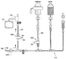
- FIG. 1 It is a figure showing typically a liquid circuit system of one form of the present invention. It is a schematic diagram which shows the function of a dual check valve. It is a figure which shows typically the switching machine holding a part of liquid circuit kit. It is a figure which shows typically the liquid circuit system of the other form of this invention. It is a figure which shows a part of process of an angiography (contrast medium suction
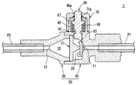
- FIG. 11 It is sectional drawing of the perpendicular direction of the one-way valve of FIG. 11, and has shown the state in which the movable pin was pushed. It is an enlarged view which expands and shows a part of FIG. It is a perspective view which shows the state by which the supporting member, the movable pin, etc. are arrange
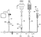
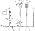
- the liquid circuit system 200 of this embodiment shown in FIG. 1 is used for, for example, cardiac catheter examination.
- the system 200 includes a liquid circuit kit 201 (detailed below), a contrast medium chamber 221, a physiological saline chamber 223, a transducer 270, and a syringe 251 connected thereto.
- the liquid circuit system 200 also includes an injection head 260 (only a part of which is shown) that holds the syringe 251 and sucks and pushes out the chemical liquid.
- the liquid circuit kit 201 in FIG. 1 specifically includes a syringe line 204 connected to the syringe 251, a contrast agent line 205 connected to the contrast agent chamber 221, and a physiological saline connected to the physiological saline chamber 223.
- the material, length, and diameter of the tubes constituting the lines 204 to 208 may be appropriately selected in consideration of the pressure applied to the tubes.
- a portion to which a high pressure is applied is preferably composed of a high pressure resistant tube.
- dual check valves 215A and 215B and release valves 202A and 202B which will be described later, preferably have a high breakdown voltage.
- the “baseline part 210” refers to a part to which the above-mentioned lines 204 to 208 are connected as shown in FIG. 1, and is composed of tubes, valves, connectors and the like.
- the syringe line 204 is connected to the upstream side of the baseline part 210 and the patient line 208 is connected to the downstream side.
- a contrast medium line 205, a physiological saline line 206, and a transducer line 207 are connected to an intermediate portion of the base line portion 210 sequentially from the upstream side.
- Each of these lines 205 to 207 is connected to the base line portion 210 in a T shape.
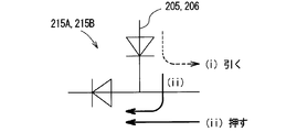
- the contrast medium line 205 and the physiological saline line 206 are connected to the base line unit 210 by dual check valves 215A and 215B, respectively.
- the two dual check valves 215A, B may be the same, or different ones having different functions may be used. In FIG. 1, the same thing is utilized as an example.
- the dual check valves 215A and 215B are valves having the following functions (see also FIG. 2A): (I) When the liquid is drawn toward the upstream side of the baseline portion 210 (that is, the syringe 251 side), the liquid is allowed to flow in that direction. (Ii) On the other hand, regarding the dual check valve 215A, when the liquid is pushed from the upstream side of the baseline portion 210 toward the downstream side, the liquid flows through the valve 215A to the downstream side. Regarding the dual check valve 215B, similarly, when the liquid is pushed toward the downstream side, or when pushed toward the valve 215B side from the physiological saline line 206 side, the liquid flows in those directions. .
- the dual check valves 215A and 215B restrict the flow from the downstream side to the upstream side and the flow toward the lines 205 and 206 as shown in FIG. 2A.
- valve 215A is arranged upstream of the dual check valve 215B, and the flow of the liquid upstream is restricted by this valve 215A. It is not pulled toward the side.
- the transducer line 207 is connected to the base line part 210 by a connector 217 having no valve function as an example.
- a three-way cock 213 is provided between the connector 217 and the dual check valve 215B.
- the arrangement position of the three-way cock 213 is not necessarily limited to this.
- the stopcock 213 may be disposed downstream of the air sensor 232 (detailed below) in the patient line 208.
- the three-way stopcock 213 is one in which one of the three lines connected thereto is closed along the direction of the lever (for example, in the state of FIG. May be prevented).
- Such a three-way cock is used when an operator discharges the liquid in the line to the outside as needed.
- the syringe 251 to which the syringe line 204 is connected may have, for example, a capacity of about several tens to 200 ml, and is preferably capable of performing high-pressure injection. If necessary, a protective cover that covers the syringe 251 may be used.
- the syringe 251 has a cylindrical cylinder member and a piston member (plunger rod) that is slidably inserted into the cylinder member.
- the piston member may be a so-called rodless type.
- the injector (injection head) 260 to which the syringe 251 is detachably mounted is not limited, but is preferably a type that can perform high-pressure injection, for example.
- the injector includes a motor that is a drive source and a presser member that moves back and forth. By pulling the presser member, the piston member of the syringe is pulled to fill the syringe with the chemical solution, while by pressing the presser member, the liquid in the syringe is pushed out.
- the contrast medium chamber 221 to which the contrast medium line 205 is connected may be a bottle-shaped container filled with a contrast medium.
- the contrast agent chamber 221 may be used while being suspended by a suspender (not shown), and the contrast agent line 205 is connected to the lower portion of the contrast agent chamber 221. This connection may be made via a needle.
- an air sensor 231 for example, an infrared sensor for detecting whether air is mixed in the liquid in the contrast medium line 205 is disposed below the contrast medium chamber 221.
- a drip chamber 233 is disposed below the air sensor 231 and on the contrast medium line 205, and the contrast medium from the contrast medium chamber 221 once drops into the chamber 233, and the contrast medium from within the chamber 233. It flows into the line 205.
- the saline chamber 223 to which the saline line 206 is connected may be, for example, a bag-like container filled with a contrast agent.
- a pressurizing unit 224 for pressurizing the bag is further provided. It is equipped (the thing of such composition is also called "pressure bag"). Commercially available pressure bags may be used.
- the pressurizing means 224 is not limited, and may compress the bag using a fluid such as air as a driving source, or compress the bag using a motor or the like as a driving source. Also good.
- a similar air sensor 231 and drip chamber 233 are also disposed in the physiological saline line 206.
- the mechanism for pressurizing the physiological saline is not limited to the above, but other configurations will be described later.
- the physiological saline line 206 is provided with a release valve 202A for switching opening and closing of the line 206.
- a specific configuration example of the release valve 202A will be described later with reference to FIGS.
- the release valve 202A has a movable member 203 that moves in response to an external force. By moving the movable member 203, the valve opening / closing state is switched to open and close the physiological saline line 206.
- the valve 202A is opened by pushing the movable member 203, and the physiological saline from the pressurized bag is configured to flow toward the baseline part 210 side.
- the transducer 270 connected to the line 207 detects blood pressure so that the patient's pulse can be monitored.
- the pulse waveform is configured to be displayed on a display 271 connected to the transducer 270.
- the transducer valve 207 is also provided with a release valve 202B similar to the release valve 202A of the physiological saline line 206. However, the direction is opposite to that of the release valve 202A. In this release valve 202B, the movable member 203 is pushed, so that the chemical liquid can flow to the transducer 270 side.
- a three-way cock 213 is disposed between the release valve 202 ⁇ / b> B of the transducer line 207 and the transducer 270. Further, the movable member 203 of one release valve 202A and the movable member 203 of the other release valve 202B are arranged to face each other. Further, the distances (L 1 , L 2 ) from the base line part 210 to the movable members 203, 203 of the valves are arranged so as not to be the same so as to correspond to the configuration of the switching machine 300 described later.
- a thin tube called a catheter (not shown) is connected to the distal end of the patient line 208, and this catheter is inserted into the patient's blood vessel.
- the catheter tip is transferred to, for example, the coronary artery, and a contrast agent or the like is injected into the blood vessel from the catheter tip.
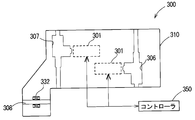
- the switching machine 300 includes a box-shaped housing 310 as an example.
- the switching device 300 includes a first holding unit 306 for holding a part of the physiological saline line 206 and a second holding unit 307 for holding a part of the transducer line 207. These holding portions 306 and 307 are formed in a concave shape, and the release valves 202A and 202B of each line are set therein.
- driving units 301 and 301 that push the movable members 203 and 203 of the valves 202A and 202B electromechanically using, for example, a motor as a driving source are provided.
- the driving units 301 and 301 may be configured to operate in response to a control signal from an external controller 350.
- the function of the controller 350 is not particularly limited, but the injector 260 may have the function.
- the switching machine 300 also includes a third holding unit 308 that holds a part of the patient line 208 and an air sensor 332 that detects the presence or absence of bubbles in the patient line 208.
- the air sensor 332 may be an ultrasonic sensor.
- the ultrasonic sensor 332 is advantageous in that, even when bubbles are mixed in the liquid under a high pressure condition, the ultrasonic sensor 332 can be found well.
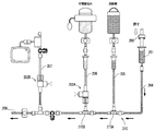
- FIG. 3 shows an initial state.
- the movable members 203 and 203 of the release valves 202A and 202B are not pushed and the liquid does not flow bidirectionally.
- the piston drive mechanism operates to pull the piston member of the syringe 251.
- the inside of the syringe 251 and the syringe line 204 becomes negative pressure, and the contrast agent in the chamber 221 is drawn into the syringe lines 205 and 204 and the syringe 251 via the contrast agent line 205 and the dual check valve 215A.
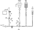
- the piston member of the syringe 251 is pushed, and the contrast agent is pushed out from the syringe 251.
- the fluid is sent to the baseline part 210 side through the syringe line 204 and passes through the two dual check valves 215A and 215B to fill the baseline part 210.
- This extrusion operation of the contrast agent is continued until the contrast agent is pushed out at least beyond the dual check valve 215B, as shown in FIG.
- the movable member 203 of the release valve 202A and the movable member 203 of the release valve 202B are pushed to open both valves 202A and 202B.
- the opening is automatically performed when the driving units 301 and 301 of the switching machine 300 press each movable member.
- the pressurizing means 224 of the physiological saline chamber 223 is driven, and a predetermined pressure (for example, about 300 mmHg) is applied to the physiological saline. Therefore, when the valve 202A is opened, the physiological saline flows from the chamber 223 side toward the base line part 210, passes through the release valve 202A and the dual check valve 215B, and flows toward the patient line 208 side.
- the contrast agent further passes through the three-way stopcock 213 and branches at the connector 217, with some flowing into the patient line 208 and the other flowing into the transducer line 207.
- the release valve 202B since the release valve 202B is opened, the physiological saline flows toward the transducer 270 beyond the release valve 202B. In this way, by filling each line with physiological saline, bubbles in the line are removed to the outside.
- the pressing of the movable member 203 of the release valve 202A of the physiological saline line 206 is released so that the physiological saline does not flow downstream beyond the release valve 202A.
- the pressing of the movable member 203 of the release valve 202B of the transducer line 207 is released so that the contrast agent does not flow into the transducer 270 side in the next contrast agent injection step, and the contrast agent or the like exceeds the release valve 202B. Make sure that it does not flow to the transducer side.
- the contrast medium in the syringe 251 is pushed out toward the patient as shown in FIG. Specifically, the contrast agent passes through the contrast agent line 204, the baseline portion 210, the patient line 208, and a catheter (not shown) to a predetermined imaging site (for example, a coronary artery of the heart) in the patient body. Sent.
- the movable member 203 of the release valve 202A of the physiological saline line 206 is pushed as shown in FIG. 8 to open the valve again.
- a predetermined pressure for example, about 300 mmHg
- the pressurizing means 224 of the pressure bag is sent to the base line part 210 and the patient line 208, and the contrast medium is flushed.
- the release valve 202B of the transducer line 207 is opened, whereby physiological saline is caused to flow further to the transducer side than the release valve 202B. Perform a flash.
- the liquid circuit kit 201 of the present embodiment includes the contrast agent line 205, the physiological saline line 206, the syringe line 204, the patient line 208, and the base line unit 210, and the contrast agent line.
- Dual check valves 215A and 215B for restricting the flow of liquid in a predetermined direction are provided at a connection portion between 205 and the baseline portion 210 and a connection portion between the physiological saline line 206 and the baseline portion 206. Therefore, it is possible to satisfactorily perform the suction of the contrast medium into the syringe 251 (FIG. 3) and the subsequent delivery of the contrast medium (FIG. 4) without requiring the operator to manually switch the three-way stopcock. Can do.
- a release valve 202A is provided in the physiological saline line 206.
- the release valve 202A switches between opening and closing by pressing the movable member 203, for example, the release valve 202A can be easily switched compared to a type in which opening and closing is switched by twisting a lever such as a three-way cock.
- a lever such as a three-way cock.
- such movement of the movable member 203 can be performed in a short time compared to the case of twisting the lever.
- the closing can be performed more reliably than when the tube is crushed and closed.
- the transducer line 207 can be satisfactorily closed using the release valve 202B, so that a high-pressure liquid transducer 270 can be used even when a high-pressure injection such as a cardiac catheter test is performed. Inflow to the side can be prevented, and as a result, breakage and damage of the transducer 270 can be prevented.
- the liquid circuit kit 201 of the present embodiment uses the contrast agent line 205, the physiological saline line 206, the syringe line 204, the transducer line 207, the patient line 208, and the base line part 210 as one set, and is used as a disposable. May be used. That is, the liquid circuit kit 200 can be used a plurality of times, but may be replaced with a new one when the use for one patient is completed for the purpose of preventing infections and the like. In this case, it may be disposable including the drip chambers 233 and 233 (only one of them) of the physiological saline line 206 and the contrast medium line 205.
- the liquid circuit system of the present embodiment uses the liquid circuit kit 200, and includes an injector that carries the syringe 251 and sucks and injects (sends out) the liquid, and a predetermined line of the liquid circuit kit 200. And a switching device 300 that automatically switches between opening and closing. According to such a system, it is possible to appropriately perform a series of injection operations of contrast medium and physiological saline without requiring the operator to switch the three-way stopcock, and if necessary, all steps Can also be performed automatically.
- the present invention is not limited to the form described above.
- a tube pump that continuously crushes the tube and flows physiological saline in the tube in a predetermined direction may be used instead of the pressure bag.
- a device that repeatedly sucks and pushes physiological saline by reciprocating the piston member of a small syringe can be used.
- This device uses a cam mechanism and a biasing member (for example, a spring). May be.
- release valves 202A and 202B usable in the liquid circuit system 200 of FIG. 1 may be as follows.
- an example of the configuration of the release valve will be described with reference to FIGS. 11 to 19, but the present invention is not limited to the following steps.
- the one corresponding to the release valves 220A and 220B will be described as “one-way valve 1”.
- the movable member 223 corresponds to the “movable pin 60”.
- the one-way valve shown in FIGS. 11 to 19 switches between a one-valve state that allows movement in only one direction of the chemical solution and an open state that allows movement in both directions.
- a release valve As a release valve, the closed state that completely blocks the movement of the liquid and the open state that allows the movement in both directions (the direction in which the liquid flows depends on the pressure difference of the liquid) can be switched. Good.
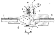
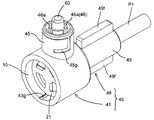
- the one-way valve 1 of this embodiment shown in FIG. 11 is mainly used for a medical liquid circuit.
- the one-way valve 1 has a high pressure resistance and can be used, for example, for cardiac catheter examination.
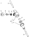
- the valve 1 moves to a casing 50 constituting the valve chamber 10, a disc-shaped valve body 25 disposed in the valve chamber 10, and a part of the casing 50.
- a movable pin 60 held in a possible manner and a cap 70 attached to the casing 50 so as to cover the movable pin 60 are provided.
- the one-way valve 1 is connected to a supply tube P1 and a discharge tube P2.
- the valve 1 basically allows only a flow from the supply tube P1 to the discharge tube P2, and allows a bidirectional flow only while the movable pin 60 is pressed.
- the flow direction of the chemical solution depends on the pressure of the chemical solution in the tubes P1 and P2, and therefore other flow directions are possible under a predetermined pressure condition. As an example, under the condition that the fluid pressure on the P2 side is higher than that on the P1 side, the chemical solution does not flow when the movable pin 60 is not pushed, and the chemical solution flows from the P2 side to the P1 side only while being pushed. It will flow.
- each component of the casing 50, the movable pin 60, the cap 70, and the support member 21 described later may be a resin molded product as an example.
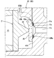
- the casing 50 has a casing body 40 to which the supply tube P1 is connected and a substantially cylindrical closure member 30 to which the discharge tube P2 is connected.
- the valve chamber 10 is formed between the two members.
- An inlet portion 11 for supplying a chemical solution into the valve chamber is formed on the upstream side of the valve chamber 10 (FIG. 12), and an outlet portion 13 for sending the chemical solution to the outside is formed on the downstream side. .
- the valve chamber 10 is generally shaped like a horizontal column, and its downstream side is tapered so that the cross-sectional area gradually decreases toward the outlet 13 side.
- a valve body 25 (details below) for opening and closing the inlet 11 and a support member 21 (details below) for holding the valve body 25 are disposed.
- the casing main body 40 is a cylindrical (one example) main body 41 constituting the valve chamber 10 and a cylindrical portion that is narrower than the main body 41 provided on the upstream side of the main body 41. And a tube holding part 48 to which P1 is connected.
- the material of the casing body 40 is not limited, but may be permeable so that the inside of the valve can be seen, or may be non-permeable.
- the end of the supply tube P1 is inserted into the tube holding part 48.
- the supply tube P1 is connected to the tube holding portion 48 with sufficient strength by a conventionally known method so that the tube does not come off even when the hydraulic pressure increases.
- One or a plurality of ribs may be formed on the tube holding portion 48 so that the supply tube P1 can be connected with good workability.
- one rib 49f, 49f projecting in the radial direction is formed on the upper portion and the lower portion of the cylindrical portion 49 one by one.
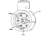
- the main body 41 has a shape in which a cylinder is turned sideways, and a valve body 25 (see FIG. 11) and a support member 21 that holds the valve body 25 are disposed therein (these elements). Details of the members are as follows). As shown in FIG. 16, an inlet portion 11 for supplying a chemical solution is formed in a part of the wall surface 41 h in the main body portion.
- the inlet 11 is provided with a recess 11a (see FIGS. 14 and 16) formed so as to partially dent the wall surface 41h, and the channel 11c communicates with the recess 11a.
- a chamfer surface 11b is formed at the boundary between the recess 11a and the flow path 11c.
- the outline shape of the recessed part 11a is circular, and the three ribs 43Ra are formed in the recessed part 11a as an example. These ribs 43Ra are radially formed at equal intervals.
- the rib 43Ra plays a role of supporting the front surface of the valve body 25 (details below).
- a plurality of support ribs 43 ⁇ / b> Rb for supporting the outer peripheral portion of the valve body 25 are formed around the inlet portion 11.
- the six support ribs 43Rb are arranged radially at equal intervals.
- the valve body 25 is, for example, a disc shape and has flexibility (a valve body that does not have flexibility will be described later again).
- the thickness of the valve body may be uniform.
- the material of the valve body may be, for example, silicone rubber, and its hardness is, for example, in the range of 5 ° to 90 °, preferably in the range of 40 ° to 80 °, more preferably in the range of 60 ° to 80 °. It may be a range.
- the valve body 25 has a diameter that can close the inlet portion 11.
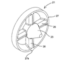
- the support member 21 for holding the valve body 25 includes a ring-shaped frame 27, a substantially cone-shaped (conical-shaped) pressing portion 23 disposed at the center thereof, and a pressing portion 23.
- the pressing portion 23 protrudes in the direction of the valve body 25 and presses the vicinity of the center portion of the back surface of the valve body 25 at the tip portion.
- valve body 25 basically blocks the inlet 11 as shown in FIG. 12, and prevents the flow from the valve chamber 10 toward the supply pipe P1.
- the outer peripheral portion of the valve body 25 is elastically deformed by the liquid pressure, thereby allowing the chemical liquid to flow into the valve chamber 10.
- the support member 21 is provided with a shape of each part in an R shape or a taper shape so that even if air bubbles are mixed into the valve chamber, the air bubbles can be discharged well outside the valve chamber. ing. Specifically, a gentle R shape is formed on the upstream side of each support arm 26 in the flow direction.
- the frame 27 is also tapered so that the thickness of the frame becomes thinner toward the upstream side in the flow direction. According to such a configuration, there is an advantage that the bubbles easily flow downstream as compared with the case where the support arms 26 and the frame 27 have a simple cross-sectional shape.
- the operation for removing bubbles is not limited, but for example, the entire valve 1 is raised so that the discharge tube P2 side is up, and the user taps the valve lightly with a hand or a predetermined tool.
- the air bubbles may be allowed to escape downstream.
- the material of the casing 40 is transparent, it is possible to visually recognize whether or not bubbles remain in the casing.
- the downstream side of the valve chamber 10 is formed in a tapered shape in which the cross-sectional area gradually decreases toward the outlet portion 13 as in the present embodiment, the bubbles can be allowed to escape well.
- each support arm 26 may be tapered so that the plate thickness becomes thinner toward the upstream side in the flow direction.
- the frame 27 may be provided with an R shape.
- the support member 21 has a configuration in which an outer peripheral portion is supported by being sandwiched between the casing body 40 and the closure member 30. According to such a configuration, there is no need to provide a dedicated part or structure for fixing the support member 21. Further, in order to prevent the support member 21 from rotating in the valve chamber 10, as shown in FIGS. 15 and 18, a protrusion 27a is formed on the outer peripheral portion of the frame 27, and this protrusion 27a is formed in the casing body. It may be adapted to engage with the longitudinal groove 43g.
- the tip shape of the movable pin 60 also has a predetermined shape, which will be described later.
- the accommodation space 15 in which the movable pin 60 is disposed is formed by an outer cylinder portion 45 (detailed below) of the casing body 40 and a cap 70 attached thereto.
- the cap 70 has a generally bottomed cylindrical shape as shown in FIGS. 12 and 19.
- the cap 70 has a flat upper surface portion 71 and a cylindrical peripheral wall portion extending downward from the peripheral portion thereof. 73.
- One opening is provided in the upper surface 71, and a part of the movable pin 60 protrudes outside through this.
- a convex portion 76 (for example, the cross-sectional shape is rectangular) is formed on the inner surface of the peripheral wall portion 73.
- one convex portion 76 is provided on each side of the peripheral wall portion 73.
- the cap 70 is attached to the casing body 40 with sufficient strength so that the cap 70 and the movable pin 60 do not come off even when a high pressure is applied to the chemical during use.
- a means for fixing the cap 70 for example, an adhesive or welding may be used, but a mechanical fixing means is more preferable.
- the mechanical fixing means for example, one in which the convex portion of one member is fitted into the concave portion of the other member, one in which the screw portions are screwed together, or an additional fixing tool such as a screw or a fixing pin is used. Then, both members may be fixed.
- the cap 70 can be fixed with sufficient strength and with high positional accuracy. If necessary, after the cap 70 is attached to the outer cylinder portion 45, further fixing may be performed with an adhesive or the like.
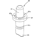
- the movable pin 60 has, for example, a circular cross-sectional shaft portion 61 and a flange portion 67 formed in a part thereof.
- an action portion 63 that comes into contact with the valve body 25 is formed.
- the action part 63 is formed in a wedge shape so that the outer peripheral part of the valve body 25 can be lifted from the wall surface 41h.
- the action part 63 has a protrusion 63a that enters between the valve body 25 and the wall surface 41h, and a flat part 63b that is formed on the downstream side of the protrusion 63a.
- the flat portion 63 is preferably configured so as to protrude from the same surface as the upper surface of the valve chamber 10 or in a state where the movable pin 63 is positioned upward as shown by a broken line in FIG. If the flat surface 63 is recessed from the upper surface of the valve chamber, bubbles may stay in this portion. However, with the above configuration, the bubbles can flow well downstream. it can.
- the shaft portion 61 is formed with an annular groove 61c for fitting an O-ring R1 (details below).
- the flange portion 67 is formed above the annular groove 61 c, and four arc-shaped guide holes 67 a are formed in the flange portion 67.
- the upper end of the shaft portion 61 is a portion that is pushed by the user or by a predetermined mechanism, and the corner portion on the outer periphery of the upper end has an R shape.
- the movable pin 60 is disposed in the outer cylinder portion 45 of the casing body 41.
- An inner cylinder portion 46 is formed inside the outer cylinder 45, and the inner cylinder portion 46 is composed of four wall pieces 46a having a circular cross section.
- each wall piece 46a is in a state of being passed through each guide hole 67a of the movable pin.
- Each wall piece 46a functions as a member for guiding the vertical movement of the movable pin 60, and plays a role of preventing the movable pin 60 from rotating around the central axis.
- the movable pin 60 configured as described above is configured to move up and down as shown in FIGS. First, the state of FIG. 12 in which the movable pin 60 is in the first position (upper position) will be described.
- the movable pin 60 is lifted upward by the biasing force of the coil spring 68 disposed below the flange portion 67 of the movable pin 60, and the upper surface of the flange portion 67 is pressed against the inner surface of the cap 70. Since the flange portion 67 is formed to have a larger diameter than the opening portion of the cap 70, the movable pin 60 does not come out of the cap. In the present embodiment, since the upper surface of the flange portion 67 and the inner surface of the cap 70 are both flat surfaces and the two members are in contact with each other, the cap 70 uniformly applies the force from the flange portion 67. Can receive.
- the one-way valve 1 functions as a one-way valve that only allows the flow from the supply tube P1 side to the discharge tube P2 side.
- the flow direction of the chemical liquid depends on the pressure of the chemical liquid in the tubes P1 and P2.
- the valve 1 is used in a liquid circuit in which the liquid pressure on the P2 side is higher than the P1 side. In this case, the chemical solution does not flow when the movable pin 60 is not pressed, and the chemical solution flows from the P2 side toward the P1 side only while the movable pin 60 is being pressed.
- the flow of the chemical solution is not limited to a specific direction as described above.
- the movable pin 60 is pushed downward and moved to the second position (downward position).
- the movable pin 60 is pushed down while resisting the urging force of the coil spring 68, and in a state where it has moved to the position shown in FIG. 13, the action portion 63 of the movable pin 60 enters between the valve body 25 and the wall surface 41h (FIG. 14). ),
- the outer peripheral portion of the valve body 25 is elastically deformed, and thereby the inlet portion 11 is opened.
- the chemical liquid can flow in both directions (which direction depends on the liquid pressure in P1 and P2).
- the communication state of the valve can be appropriately switched by pressing the movable pin 60.
- the means for pushing the movable pin 1 is not particularly limited.
- the user may push the movable pin 60 by hand or using a predetermined tool, or the predetermined mechanism is to push the movable pin 60. Also good.
- each wall piece 46a is configured to fit into a locking groove 71g formed on the inner surface of the upper surface portion 71 of the cap 70. Therefore, the front end side of the inner cylindrical portion 46 is prevented from expanding, and as a result, the sealing performance by the O-ring R1 is kept good even during use.
- the movable pin 60 may be a polyacetal resin (POM) having a good sliding property.
- the component constituting the casing 50 may be polycarbonate resin (PC).
- the outer peripheral surface of the valve body 25 in particular, the surface facing the wall surface 41h) may be provided with a fine uneven shape.
- the one-way valve 1 of this embodiment can temporarily cancel the function of the one-way valve by moving the movable pin 60.
- this movable pin 60 is arrange
- FIG. Therefore, even if a large force is applied in such a direction that the pressure of the chemical solution rises and pushes the movable pin 60 against the movable pin 60 during use, the force is received by the cap 70 via the flange portion 67 and is movable.
- the pin 60 does not come off. Therefore, the one-way valve 1 of the present embodiment can cope with high-pressure injection of a chemical solution.
- the cap 70 is fixed to the casing 50 using mechanical fixing means (45g, 76). Therefore, for example, the cap 70 can be fixed with sufficient strength and high positional accuracy as compared with the case where the cap 70 is fixed using only an adhesive.
- the inlet portion 11 since the concave portion 11a as shown in FIG. 16 is formed in the inlet portion 11 of the valve chamber 10, the inlet portion 11 can be reliably opened only by slightly deforming the valve body 25. it can. That is, if such a recess 11a is not formed, it is necessary to deform the valve body 25 to the extent that the central flow path 11c is opened in order to open the inlet 11.
- the concave portion 11a when the outer peripheral portion of the valve body 25 is deformed, the concave portion 11a is opened and the flow passage 11c communicating therewith is also opened.
- the inlet 11 can be opened and closed with a slight deformation of the valve body 25.
- the hydraulic pressure applied to the back surface of the valve body 25 during use of the valve becomes a problem. That is, depending on in which liquid circuit the valve 1 is used, if the hydraulic pressure in the valve chamber 10 becomes very high at the time of use, the valve body 25 is moved to the recess 11a side by the hydraulic pressure. It is assumed that it will be pushed to. In this case, if the support rib 43Ra is not provided in the recess 11a, the valve body 25 may be stuck to the recess 11a. In this state, even if the action portion 63 of the movable pin 60 is pushed between the valve body 25 and the wall surface 41h, the inlet portion 11 may not be sufficiently opened.
- the support rib 43Ra is not necessarily limited to the shape shown in FIG. 16, and a protrusion having an arbitrary shape protruding from the bottom of the recess 11a may be formed.
- the present invention is not limited to the above and can be variously modified.
- the valve body 25 may not have flexibility.
- the valve body is a plate-shaped member having no flexibility, and is configured to be displaceable between (a) a position where the inlet portion 11 is closed and (b) a position where the inlet portion 11 is opened. It may be.
- the support member 21 may have a configuration in which at least the pressing portion 23 has elasticity and the pressing portion is elastically contracted to allow the displacement of the valve body.
- the shape of the pressing portion of the support member is not limited to the conical shape, and may be, for example, a truncated cone shape. By adopting such a shape, the valve body can be pressed in a wider area.
- the shape of the cap 70 is not particularly limited as long as it is fixed to the casing 50 with sufficient strength so that the movable pin 60 does not come off when the one-way valve 1 is used. It is good also as a shape.
- the shape of the movable pin 60 is not limited as long as the movable pin 60 is moved by receiving a force from the outside and moves the valve body 25 thereby, and may have a shape other than the pin shape.
- the cross-sectional shape is not limited to a circle, but may be a rectangle, a polygon, or the like.
- the structure in which the flange portion 67 of the movable pin 60 contacts the upper surface of the cap 70 is exemplified as a structure for preventing the movable pin 60 from coming off.
- the structure for preventing the removal is limited to the flange.
- it may be a simple protrusion or the like provided on the outer periphery of the movable pin.
- an additional cap (not shown) may be attached to the protruding portion of the movable pin 60 so that the user can easily push the movable pin 60 by hand.
- the casing 50 is composed of the casing body and the closure member 30, but the number of parts and the shape of the casing are not limited as long as the casing forms the valve chamber 10.
- the valve body 25 is not limited to a circular contour shape, and may have a contour shape such as an ellipse, a rectangle, or a polygon. In the above description, it is assumed that the thickness of the valve body 25 is constant, but the thickness of the valve body 25 may be different depending on the part.
- the one-way valve according to another embodiment of the present invention may be as follows.
- a casing constituting a valve chamber having a liquid inlet and outlet;
- a valve body that is arranged to close the inlet in the valve chamber and is configured to be elastically deformable or displaceable to open the inlet;
- a movable member movably held in the casing, wherein the movable member abuts the valve body by moving and elastically deforms or displaces the valve body;
- a one-way valve with an opening function in which when the movable member is pushed, an amount of chemical corresponding to the amount of movement is pushed out of the valve chamber through the outlet.
- the valve is configured such that when the movable pin 60 is pushed, a small amount of chemical corresponding to the amount of movement is pushed out from the valve chamber 10.
- the movable pin 68 is returned to the original position by the coil spring 68, and the valve body 25 is temporarily deformed to refill the valve chamber 10 with the chemical solution again.
- the function of pushing out a small amount of liquid medicine by operating the movable pin 60 is particularly effective when, for example, a contrast medium is injected in a cardiac catheter test.
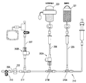
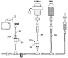
- a pump device 226 as shown in FIG. 20 may be used instead of the pressurizing means 224 for physiological saline (FIG. 1).
- FIG. 20 only a part of the chemical circuit system is shown. About the structure downstream from the three-way cock 213, the thing similar to FIG. 1 can be used.
- the pump device 226 is of the type disclosed in Japanese Patent No. 3626264, for example.
- the pump device 226 includes a main body 227 on which a small syringe 226a is mounted, and a piston drive mechanism (not shown) that moves the piston member of the syringe 226a back and forth.
- a part of the circuit is changed from that of FIG. Specifically, connectors 215C and 215D are used in place of the check valves 215A and 215B, and a one-valve V-1 is disposed between both connectors.
- the one-way valve V-1 is arranged so as to allow the flow to the downstream side and not to allow the flow in the opposite direction, as indicated by the triangular mark in FIG. Similarly to this, the flow restriction direction of the other one-way valve follows the direction of the triangle mark in FIG.
- a connector 234, an infusion chamber 233, an air sensor 231 and a one-way valve V-2 are arranged in this order from the side close to the chamber 221.
- the arrangement of these components 234, 233, 231 can be changed as appropriate.
- the line 206 connecting the connector 215D and the physiological saline chamber 223 is divided into two on the way, one of which is the line 206 and the other is the line 209 that goes to the pump device 226. As shown in FIG. 20, two one-way valves V-3 and V-4 are arranged in the line 206.
- One one-way valve V-5 is also provided between the connector 215D and the three-way cock 213.
- the one-way valve V-5 may be omitted.
- a circuit downstream from the one valve may be made disposable.
- the circuit downstream from the connector 215D may be used as the disposal regardless of the presence or absence of the one-way valve V-5.
- a chemical liquid tube (not shown) may be connected to the three-way cock 213, and the chemical liquid may be injected toward the patient via the chemical liquid tube.
- the pump device 226 is operated to move the piston member of the small syringe 226a forward and backward, so that (i) physiological saline from the chamber 223 into the syringe 226a Suction and (ii) discharge of physiological saline from the small syringe 226a are repeated. Thereby, physiological saline is inject
- a load sensor 223S for measuring the weight of the physiological saline chamber 223 is provided as an example.
- the control device (not shown) is based on the output value of the load sensor 223S or a value obtained by converting the load sensor 223S into a load. Whether or not) When it is determined that the value is equal to or less than a predetermined set value, a predetermined warning (for example, lighting of a lamp, display of a message, output of sound or sound, etc.) is issued to the surgeon.
- a predetermined warning for example, lighting of a lamp, display of a message, output of sound or sound, etc.
- load sensor 223S as described above can also be used in the chemical circuit system of the embodiment of FIG.
- a connector having a floating valve body as disclosed in Japanese Patent Application Laid-Open No. 9-117505 can be used as an example of an infusion chamber. , Air contamination on the patient line side is prevented. Further, it may be determined based on the position of the valve body whether or not it is empty, and if it is empty, control such as stopping injection may be performed.
- the chemical circuit system of FIG. 20 includes the following liquid circuit kit: A medical liquid circuit kit used for angiography, A contrast agent line connected to the contrast agent chamber; A saline line connected to the saline chamber; A syringe line connected to the syringe; A patient line for delivering contrast media or saline to the patient; A baseline part to which each line is connected, wherein the contrast medium line and the physiological saline line are each connected in a T-shape; and
- a (i) When the liquid is drawn toward the upstream side of the baseline portion, the contrast medium flows from the line into the baseline portion, and (ii) the liquid flows from the upstream side of the baseline portion.
- a first valve means (V-1, V-2) configured to pass through the valve means and flow liquid in that direction when pushed toward the downstream side;
- Second valve means (V-1) which allows the liquid to flow in the direction when the liquid is pushed from the upstream side to the downstream side of the baseline portion but does not allow the reverse flow.
- c When the physiological saline is sent from the physiological saline chamber by the physiological saline feeding means, the physiological saline is allowed to flow to the patient line side, and the flow to the syringe line side is not allowed.
- Valve means (V-3, V-1); A liquid circuit kit for medical use.
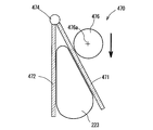
- a roller type pump 470 as shown in FIG. 21 can also be used as means for sending out the chemical liquid by pressurizing the chemical liquid chamber.
- the pump 470 includes a pair of pressing members 471 and 472 arranged so as to sandwich the chamber 223 therebetween. When one of the pressing members 471 and 472 comes close to the other, the chamber 223 between both the members 471 and 472 is pressed, and thereby the chemical solution inside the chamber 223 is pushed out.
- both members may be connected by a hinge portion 474 so that one of the members rotates with respect to the other.
- a roller 476 may be provided to bring one member close toward the other.
- the roller 476 rotates around the rotation center 476a (there may or may not be a drive source) and moves downward as indicated by an arrow in the figure, and the pressing member 471 is directed toward the other member 472.
- You may be comprised so that it may press.
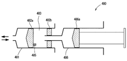
- a piston type pump 480 as shown in FIG. 22 can be used.
- the pump 480 includes two syringes 481 and 486 connected in series, and the front end portion of the front syringe 481 is connected to a line 209 (see FIG. 20).
- a short gasket 482a is slidably disposed in the front syringe 481, and a protrusion 485 is formed on the back surface of the gasket 482a.
- the protrusion 485 is not necessarily formed, but plays a role of defining a movable range when the gasket 482a moves rearward.
- the tip of the rear syringe 486 is formed to be thin and inserted into a through hole formed in the sealing member 482b of the front syringe 481.
- the pump 480 is also provided with driving means (not shown) for moving the piston member of the rear syringe 486 back and forth.
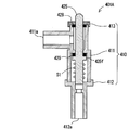
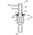
- the release valves 202A and 202B in FIG. 1 may be configured as shown in FIG. It should be noted that a part of the configuration is schematically drawn in FIG. 23 (and FIG. 24 described later).
- a release valve 401A in FIG. 23 includes a hollow main body member 411, a tube connection member 412 connected to a lower portion thereof, and a cap member 413 that closes an upper end opening of the main body member 411 as members constituting the casing 410.
- a shaft member 425 is disposed inside the main body member 411 so as to be movable upward and downward.
- the shaft member 425 is provided with two seal members 428 and 429, and a flange portion 425f is formed on a part of the shaft member 425.
- the shaft member 425 is biased upward by the coil spring S1 (FIG. 23), and in this state, the flange portion 425f presses against the seal member 429. In this state, fluid does not flow from the lower end opening 412a of the connection member 412 toward the side opening 411a of the main body member 411 (or vice versa).
- a part of the flow path may be formed by a groove formed along the longitudinal direction of the outer periphery of the shaft member 425.
- a release valve 401A as shown in FIG. 23 may be used.
- a release valve 401B as shown in FIG. 24 may be used.
- the release valve 401B of FIG. 24 includes a hollow main body member 411 and a cap member 413 that closes the upper end opening as members constituting the casing 410.
- a shaft member 425 is arranged inside the main body member 411 so as to be movable upward and downward.
- the shaft member 425 is provided with one seal member 429 and an O-ring R1.
- a pressing member 416 having a channel formed therein is attached to the upper end of the shaft member 425 that protrudes upward from the cap member 413.
- the pressing member 416 has a side opening 416a serving as a fluid inlet / outlet.
- an octopus tube may be provided at an arbitrary position of the circuit in order to prevent air bubbles from being injected into the patient.
- an octopus pipe may be provided between the connector 217 and the air sensor 232 in the configuration of FIG.
- the “octopus tube” is a protrusion (such as any outer shape) that is a hollow head formed inside the cavity, and the bubbles that flow through the fluid circuit. It is for capturing.
- the octopus pipe is arranged so as to protrude vertically upward. Moreover, it is preferable to provide in the location where the direction of a line (tube) is stable among circuit systems so that the attitude
- One-way valve 200 Liquid circuit system 201 Liquid circuit kit 202A, 202B Release valve 203 Movable member 205 Contrast agent line 206 Saline line 207 Transducer line 208 Patient line 209 Line 210 Base line part 213 Three-way stopcocks 215A, 215B Dual check valve 215C 215D Connector 223 Saline chamber 223S Sensor 226 Pump device 226a Syringe 227 Body part 231, 232 Air sensor 251 Syringe 260 Injector 270 Transducer 300 Switching machine 301 Drive part 332 Air sensor 401A, 401B Release valve 410 Casing 411 Body member 412 Tube connection member 413 Cap member 428, 429 Seal member 470 Roller type pump 476 Roller 480 Piston type pump 481, 486 Syringe V-1 to V-1 One-way valve S1 Coil spring
Landscapes
- Health & Medical Sciences (AREA)
- Heart & Thoracic Surgery (AREA)
- Hematology (AREA)
- Anesthesiology (AREA)
- Biomedical Technology (AREA)
- Engineering & Computer Science (AREA)
- Life Sciences & Earth Sciences (AREA)
- Animal Behavior & Ethology (AREA)
- General Health & Medical Sciences (AREA)
- Public Health (AREA)
- Veterinary Medicine (AREA)
- Vascular Medicine (AREA)
- Pulmonology (AREA)
- Emergency Medicine (AREA)
- Infusion, Injection, And Reservoir Apparatuses (AREA)
Priority Applications (2)
| Application Number | Priority Date | Filing Date | Title |
|---|---|---|---|
| CN201280044808.9A CN103813818B (zh) | 2011-07-14 | 2012-07-13 | 医疗用的液体回路套装和使用该液体回路套装的液体回路系统 |
| JP2013524009A JP6071880B2 (ja) | 2011-07-14 | 2012-07-13 | 医療用の液体回路キットおよびそれを使用する液体回路システム |
Applications Claiming Priority (2)
| Application Number | Priority Date | Filing Date | Title |
|---|---|---|---|
| JP2011-156089 | 2011-07-14 | ||
| JP2011156089 | 2011-07-14 |
Publications (1)
| Publication Number | Publication Date |
|---|---|
| WO2013008929A1 true WO2013008929A1 (ja) | 2013-01-17 |
Family
ID=47506204
Family Applications (1)
| Application Number | Title | Priority Date | Filing Date |
|---|---|---|---|
| PCT/JP2012/067990 WO2013008929A1 (ja) | 2011-07-14 | 2012-07-13 | 医療用の液体回路キットおよびそれを使用する液体回路システム |
Country Status (3)
| Country | Link |
|---|---|
| JP (4) | JP6071880B2 (es) |
| CN (2) | CN103813818B (es) |
| WO (1) | WO2013008929A1 (es) |
Cited By (6)
| Publication number | Priority date | Publication date | Assignee | Title |
|---|---|---|---|---|
| CN106975120A (zh) * | 2017-04-19 | 2017-07-25 | 钟建筑 | 一种输液瓶自动换瓶装置 |
| CN109350114A (zh) * | 2018-11-28 | 2019-02-19 | 广东省人民医院(广东省医学科学院) | 一种多功能心脏彩超声学造影检查装置 |
| WO2020004581A1 (ja) * | 2018-06-29 | 2020-01-02 | 株式会社サーキュラス | 薬液注入装置 |
| CN110639082A (zh) * | 2019-09-27 | 2020-01-03 | 南通大学 | 一种具有自动换瓶输液功能的点滴装置 |
| CN110869069A (zh) * | 2018-09-05 | 2020-03-06 | 深圳市迈威生物科技有限公司 | 可弃组件及流体输送系统 |
| WO2023117771A1 (en) | 2021-12-20 | 2023-06-29 | P&R Medical | Fluid delivery system |
Families Citing this family (7)
| Publication number | Priority date | Publication date | Assignee | Title |
|---|---|---|---|---|
| SG11201804778RA (en) * | 2016-02-09 | 2018-07-30 | Bracco Injeneering S A | Method of operating an injection system |
| WO2019046260A1 (en) * | 2017-08-31 | 2019-03-07 | Bayer Healthcare Llc | METHOD FOR CONTROLLING DYNAMIC PRESSURE IN A FLUID INJECTOR SYSTEM |
| CN107929870B (zh) * | 2017-12-15 | 2023-09-19 | 广东省人民医院(广东省医学科学院) | 单气缸双管造影装置 |
| JP7128985B2 (ja) * | 2018-04-17 | 2022-09-01 | 株式会社ジェイ・エム・エス | 輸液セット |
| CN108939219B (zh) * | 2018-07-06 | 2021-03-19 | 深圳市国赛生物技术有限公司 | 柱塞泵容腔内的气泡去除方法、气泡去除系统及存储介质 |
| KR102491623B1 (ko) * | 2019-11-01 | 2023-01-27 | 김용현 | 약액 공급 조절 장치, 약액 공급 조절 장치용 리저버 어셈블리 및 이를 포함하는 약액 주입 장치 |
| JP7144464B2 (ja) * | 2020-01-20 | 2022-09-29 | ディーブイエックス株式会社 | 造影剤注入装置及び注入ラインキット |
Citations (5)
| Publication number | Priority date | Publication date | Assignee | Title |
|---|---|---|---|---|
| WO2000000768A1 (fr) * | 1998-06-29 | 2000-01-06 | Sugan Co., Ltd. | Appareil commutateur de canaux |
| JP2003199823A (ja) * | 2001-11-05 | 2003-07-15 | Suugan Kk | 流路切替装置およびその装置に用いる造影剤注入用チューブ |
| JP2004065737A (ja) * | 2002-08-08 | 2004-03-04 | Nemoto Kyorindo:Kk | 薬液注入装置 |
| JP2004357985A (ja) * | 2003-06-05 | 2004-12-24 | Nemoto Kyorindo:Kk | 薬液注入装置 |
| JP2007508061A (ja) * | 2003-10-10 | 2007-04-05 | ボストン サイエンティフィック リミテッド | 液体から気体を除去する装置及び方法。 |
Family Cites Families (11)
| Publication number | Priority date | Publication date | Assignee | Title |
|---|---|---|---|---|
| JPH0325369A (ja) * | 1989-06-22 | 1991-02-04 | Toshiba Corp | 自動化学分析装置用チェックバルブ |
| US6315762B1 (en) * | 1996-11-14 | 2001-11-13 | Angiodynamics, Inc. | Contrast medium delivery system and associated method |
| JP4293689B2 (ja) * | 1999-10-05 | 2009-07-08 | 株式会社根本杏林堂 | 造影剤注入装置 |
| US6626862B1 (en) * | 2000-04-04 | 2003-09-30 | Acist Medical Systems, Inc. | Fluid management and component detection system |
| US7172572B2 (en) * | 2001-10-04 | 2007-02-06 | Boston Scientific Scimed, Inc. | Manifold system for a medical device |
| US6918907B2 (en) * | 2003-03-13 | 2005-07-19 | Boston Scientific Scimed, Inc. | Surface electrode multiple mode operation |
| WO2005007220A1 (ja) * | 2003-07-18 | 2005-01-27 | Nemoto Kyorindo Co., Ltd. | 入力操作された注入条件を画像表示する薬液注入装置 |
| US20080167621A1 (en) * | 2005-05-16 | 2008-07-10 | Wagner Gary S | Multi-Barrel Syringe Having Integral Manifold |
| JP2007222656A (ja) * | 2007-04-10 | 2007-09-06 | Medrad Inc | 流体搬送システム、圧力隔離機構、インジェクタ制御機構、及びそれらを用いる方法 |
| WO2011055790A1 (ja) * | 2009-11-09 | 2011-05-12 | 株式会社根本杏林堂 | 開放機能付き一方弁、該一方弁を備えたチューブユニットおよび薬液注入システム |
| EP2506889B1 (en) * | 2009-12-03 | 2018-06-13 | Jean-Pierre Peters | Fluid interconnection set with particle filter |
-
2012
- 2012-07-13 CN CN201280044808.9A patent/CN103813818B/zh not_active Expired - Fee Related
- 2012-07-13 WO PCT/JP2012/067990 patent/WO2013008929A1/ja active Application Filing
- 2012-07-13 JP JP2013524009A patent/JP6071880B2/ja active Active
- 2012-07-13 CN CN201610833688.0A patent/CN106943642B/zh active Active
-
2016
- 2016-12-27 JP JP2016253078A patent/JP6316924B2/ja active Active
-
2018
- 2018-03-28 JP JP2018061576A patent/JP6676686B2/ja active Active
-
2020
- 2020-03-12 JP JP2020042737A patent/JP2020096989A/ja active Pending
Patent Citations (5)
| Publication number | Priority date | Publication date | Assignee | Title |
|---|---|---|---|---|
| WO2000000768A1 (fr) * | 1998-06-29 | 2000-01-06 | Sugan Co., Ltd. | Appareil commutateur de canaux |
| JP2003199823A (ja) * | 2001-11-05 | 2003-07-15 | Suugan Kk | 流路切替装置およびその装置に用いる造影剤注入用チューブ |
| JP2004065737A (ja) * | 2002-08-08 | 2004-03-04 | Nemoto Kyorindo:Kk | 薬液注入装置 |
| JP2004357985A (ja) * | 2003-06-05 | 2004-12-24 | Nemoto Kyorindo:Kk | 薬液注入装置 |
| JP2007508061A (ja) * | 2003-10-10 | 2007-04-05 | ボストン サイエンティフィック リミテッド | 液体から気体を除去する装置及び方法。 |
Cited By (10)
| Publication number | Priority date | Publication date | Assignee | Title |
|---|---|---|---|---|
| CN106975120A (zh) * | 2017-04-19 | 2017-07-25 | 钟建筑 | 一种输液瓶自动换瓶装置 |
| WO2020004581A1 (ja) * | 2018-06-29 | 2020-01-02 | 株式会社サーキュラス | 薬液注入装置 |
| JPWO2020004581A1 (ja) * | 2018-06-29 | 2021-08-12 | 株式会社サーキュラス | 薬液注入装置 |
| JP7304347B2 (ja) | 2018-06-29 | 2023-07-06 | 株式会社サーキュラス | 薬液注入装置 |
| CN110869069A (zh) * | 2018-09-05 | 2020-03-06 | 深圳市迈威生物科技有限公司 | 可弃组件及流体输送系统 |
| CN110869069B (zh) * | 2018-09-05 | 2021-04-06 | 深圳市迈威生物科技有限公司 | 可弃组件及流体输送系统 |
| CN109350114A (zh) * | 2018-11-28 | 2019-02-19 | 广东省人民医院(广东省医学科学院) | 一种多功能心脏彩超声学造影检查装置 |
| CN110639082A (zh) * | 2019-09-27 | 2020-01-03 | 南通大学 | 一种具有自动换瓶输液功能的点滴装置 |
| WO2023117771A1 (en) | 2021-12-20 | 2023-06-29 | P&R Medical | Fluid delivery system |
| BE1028541B1 (nl) * | 2021-12-20 | 2023-07-12 | P&R Medical Bv | Vloeistofafgiftesysteem |
Also Published As
| Publication number | Publication date |
|---|---|
| CN103813818A (zh) | 2014-05-21 |
| CN103813818B (zh) | 2016-10-19 |
| JP2017094128A (ja) | 2017-06-01 |
| JP6316924B2 (ja) | 2018-04-25 |
| JP6676686B2 (ja) | 2020-04-08 |
| JP2018118099A (ja) | 2018-08-02 |
| CN106943642B (zh) | 2020-11-27 |
| JPWO2013008929A1 (ja) | 2015-02-23 |
| JP6071880B2 (ja) | 2017-02-01 |
| JP2020096989A (ja) | 2020-06-25 |
| CN106943642A (zh) | 2017-07-14 |
Similar Documents
| Publication | Publication Date | Title |
|---|---|---|
| JP6316924B2 (ja) | 医療用の液体回路キットおよびそれを使用する液体回路システム | |
| JP6002039B2 (ja) | 医療管類セットにおける二重逆止弁配列の機能を査定するためのシステムおよび方法 | |
| JP2018167058A (ja) | 薬液回路およびそれを使用する薬液回路システム | |
| JP5735498B2 (ja) | 流体注入デバイスの流路から空気を除去する方法およびシステム | |
| US11826541B2 (en) | Sliding syringe cap for separate filling and delivery | |
| EP2364172B1 (en) | Mating mechanism for a pressurizing unit and corresponding sleeve in a medical fluid injection device | |
| JP7543626B2 (ja) | 閉鎖機構、薬液回路、及び注入システム | |
| JP2018161507A (ja) | 流入動作が制限された一方弁、該一方弁を備えたチューブユニットおよび薬液注入システム | |
| JP5800713B2 (ja) | 開放機能付き一方弁を備えたチューブユニットを有する薬液注入システム | |
| JP4902096B2 (ja) | 薬液シリンジ | |
| JPWO2004108192A1 (ja) | 薬液供給制御方法、その方法に使用する薬液供給制御装置及びその装置を用いた薬液投与セット | |
| US20070250008A1 (en) | Fluid injection apparatus and adaptor pump therefor | |
| JP5936825B2 (ja) | 開放機能付き一方弁 | |
| CN114980943B (zh) | 造影剂注入装置以及注入管线套件 | |
| JP7549089B2 (ja) | 薬液注入装置 | |
| JP6856977B2 (ja) | クランプ、閉鎖装置及び薬液回路 |
Legal Events
| Date | Code | Title | Description |
|---|---|---|---|
| 121 | Ep: the epo has been informed by wipo that ep was designated in this application |
Ref document number: 12811275 Country of ref document: EP Kind code of ref document: A1 |
|
| ENP | Entry into the national phase |
Ref document number: 2013524009 Country of ref document: JP Kind code of ref document: A |
|
| NENP | Non-entry into the national phase |
Ref country code: DE |
|
| 122 | Ep: pct application non-entry in european phase |
Ref document number: 12811275 Country of ref document: EP Kind code of ref document: A1 |