WO2013008621A1 - コイルの巻線方法及び巻線装置 - Google Patents
コイルの巻線方法及び巻線装置 Download PDFInfo
- Publication number
- WO2013008621A1 WO2013008621A1 PCT/JP2012/066327 JP2012066327W WO2013008621A1 WO 2013008621 A1 WO2013008621 A1 WO 2013008621A1 JP 2012066327 W JP2012066327 W JP 2012066327W WO 2013008621 A1 WO2013008621 A1 WO 2013008621A1
- Authority
- WO
- WIPO (PCT)
- Prior art keywords
- winding
- unit
- coil
- shaft
- shaft body
- Prior art date
Links
Images


Classifications
-
- H—ELECTRICITY
- H01—ELECTRIC ELEMENTS
- H01F—MAGNETS; INDUCTANCES; TRANSFORMERS; SELECTION OF MATERIALS FOR THEIR MAGNETIC PROPERTIES
- H01F41/00—Apparatus or processes specially adapted for manufacturing or assembling magnets, inductances or transformers; Apparatus or processes specially adapted for manufacturing materials characterised by their magnetic properties
- H01F41/02—Apparatus or processes specially adapted for manufacturing or assembling magnets, inductances or transformers; Apparatus or processes specially adapted for manufacturing materials characterised by their magnetic properties for manufacturing cores, coils, or magnets
- H01F41/04—Apparatus or processes specially adapted for manufacturing or assembling magnets, inductances or transformers; Apparatus or processes specially adapted for manufacturing materials characterised by their magnetic properties for manufacturing cores, coils, or magnets for manufacturing coils
- H01F41/06—Coil winding
- H01F41/064—Winding non-flat conductive wires, e.g. rods, cables or cords
-
- H—ELECTRICITY
- H01—ELECTRIC ELEMENTS
- H01F—MAGNETS; INDUCTANCES; TRANSFORMERS; SELECTION OF MATERIALS FOR THEIR MAGNETIC PROPERTIES
- H01F27/00—Details of transformers or inductances, in general
- H01F27/28—Coils; Windings; Conductive connections
- H01F27/2823—Wires
-
- B—PERFORMING OPERATIONS; TRANSPORTING
- B21—MECHANICAL METAL-WORKING WITHOUT ESSENTIALLY REMOVING MATERIAL; PUNCHING METAL
- B21F—WORKING OR PROCESSING OF METAL WIRE
- B21F3/00—Coiling wire into particular forms
- B21F3/10—Coiling wire into particular forms to spirals other than flat, e.g. conical
-
- H—ELECTRICITY
- H01—ELECTRIC ELEMENTS
- H01F—MAGNETS; INDUCTANCES; TRANSFORMERS; SELECTION OF MATERIALS FOR THEIR MAGNETIC PROPERTIES
- H01F41/00—Apparatus or processes specially adapted for manufacturing or assembling magnets, inductances or transformers; Apparatus or processes specially adapted for manufacturing materials characterised by their magnetic properties
- H01F41/02—Apparatus or processes specially adapted for manufacturing or assembling magnets, inductances or transformers; Apparatus or processes specially adapted for manufacturing materials characterised by their magnetic properties for manufacturing cores, coils, or magnets
- H01F41/04—Apparatus or processes specially adapted for manufacturing or assembling magnets, inductances or transformers; Apparatus or processes specially adapted for manufacturing materials characterised by their magnetic properties for manufacturing cores, coils, or magnets for manufacturing coils
- H01F41/06—Coil winding
- H01F41/082—Devices for guiding or positioning the winding material on the former
- H01F41/086—Devices for guiding or positioning the winding material on the former in a special configuration on the former, e.g. orthocyclic coils or open mesh coils
-
- H—ELECTRICITY
- H01—ELECTRIC ELEMENTS
- H01F—MAGNETS; INDUCTANCES; TRANSFORMERS; SELECTION OF MATERIALS FOR THEIR MAGNETIC PROPERTIES
- H01F41/00—Apparatus or processes specially adapted for manufacturing or assembling magnets, inductances or transformers; Apparatus or processes specially adapted for manufacturing materials characterised by their magnetic properties
- H01F41/02—Apparatus or processes specially adapted for manufacturing or assembling magnets, inductances or transformers; Apparatus or processes specially adapted for manufacturing materials characterised by their magnetic properties for manufacturing cores, coils, or magnets
- H01F41/04—Apparatus or processes specially adapted for manufacturing or assembling magnets, inductances or transformers; Apparatus or processes specially adapted for manufacturing materials characterised by their magnetic properties for manufacturing cores, coils, or magnets for manufacturing coils
- H01F41/06—Coil winding
- H01F41/098—Mandrels; Formers
-
- H—ELECTRICITY
- H01—ELECTRIC ELEMENTS
- H01F—MAGNETS; INDUCTANCES; TRANSFORMERS; SELECTION OF MATERIALS FOR THEIR MAGNETIC PROPERTIES
- H01F5/00—Coils
Definitions
- the present invention relates to a winding method and a winding device for a coil composed of a plurality of coil layers.
- the applicant has developed a coil (2) in which unit coil portions (23) formed by winding a conducting wire (22) in a spiral shape are repeatedly arranged in the winding axis direction.
- a first unit winding part (25) and a second unit having different inner circumferential lengths are obtained by winding a conducting wire in a spiral shape.
- the winding part (26) and the third unit winding part (27) are formed continuously in the winding axis direction, and the unit coil part composed of the plurality of unit winding parts (25) (26) (27) is wound.
- the intermediate product (20) of the air-core coil continuously formed in the axial direction the intermediate product (20) is compressed in the winding axis direction, and the third unit as shown in FIG.
- Patent Document 1 a method for obtaining a finished product (21) of an air-core coil composed of a plurality of coil layers (three layers in the illustrated example) is known (Patent Document 1).
- Patent Document 1 As a method for producing the intermediate product (20) of the air-core coil shown in FIG. 18 (a), a method using a stepped winding jig corresponding to the cavity shape of the intermediate product (20) (Patent Document 1). In addition, an automatic winding machine is known that winds a conductor around the core member while changing the form of the core member for each winding step of each unit winding part (Patent Document 2).
- the method using a stepped winding jig has a problem of poor production efficiency because the winding work is a manual work.
- an automatic winding machine that winds a conductor around the core member while changing the form of the core member for each winding process of each unit winding part, for each winding process of each unit winding part
- the configuration for changing the form of the core member is complicated.
- an object of the present invention is to form a plurality of unit winding portions having different inner peripheral lengths in a simple configuration, continuously in the winding axis direction, and to wind a unit coil portion composed of the plurality of unit winding portions. It is an object to provide a coil winding method and a winding apparatus capable of producing a coil continuously formed in the axial direction.
- a plurality of unit winding portions having different inner peripheral lengths are continuously formed in the winding axis direction, and each unit winding portion is formed in a loop shape having a plurality of arc-shaped corner portions.
- a coil unit is wound along the winding path, and a unit coil unit composed of the plurality of unit coil units is formed continuously in the winding axis direction.
- the plurality of unit winding portions constituting each unit coil portion are formed in an arc shape in which a plurality of corner portions formed at the same phase angle with respect to the winding axis have a center of curvature at the same position. .
- a plurality of unit winding portions having different inner peripheral lengths are continuously formed in the winding axis direction, and each unit winding portion has a plurality of arc-shaped corner portions.
- a winding method of a coil wound along a loop-shaped winding path wherein a unit coil portion composed of the plurality of unit winding portions is continuously formed in a winding axis direction,
- the pressing member (61) By rotating the pressing member (61) to press the conducting wire (22) along a circumferential path centering on the shaft body (5), the conducting wire (22) is placed on the outer peripheral surface of the shaft body (5).
- a second step of forming an arcuate corner by winding a predetermined angle, and forming one unit winding by repeating the first step and the second step by the number of corners In the process of forming the unit winding part, by changing the outer diameter of the shaft body (5) at the time of forming each corner part, in the plurality of unit winding parts constituting each unit coil part, the same with respect to the winding axis A plurality of corner portions formed at the phase angle are formed in an arc shape having a center of curvature at the same position and different curvature radii.
- each unit coil portion is multilayered at least partially.
- a plurality of unit winding portions having different inner peripheral lengths are formed continuously in the winding axis direction, and each unit winding portion has a plurality of arc-shaped corner portions.
- a coil winding device that is wound along a loop-shaped winding path, and in which a unit coil portion including the plurality of unit winding portions is continuously formed in a winding axis direction,
- the shaft (5) A conductor transfer mechanism (4) for transferring the conductor (22) along a straight transition path intersecting with the shaft body (5) and for bringing the conductor (22) along the outer peripheral surface of the shaft body (5); , By rotating the pressing member (61) to press the conducting wire (22) along a circumferential path centering on the shaft body (5), the conducting wire (22) is placed on the outer peripheral surface of the shaft body (5). Bending mechanism to bend along (6) And has.
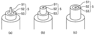
- the shaft body (5) is composed of a plurality of shaft portions (51), (52), and (53) arranged on a concentric shaft with the winding shaft, and the shaft body (5)
- the shaft portion (51) is connected to a reciprocating drive mechanism for reciprocally moving the other shaft portions (52) and (53) along the winding shaft.
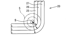
- a guide plate (9) is provided that surrounds the shaft (5) and guides the lead wire (22) bent in a loop shape by the bending mechanism (6).
- the surface of the guide plate (9) has an inclination corresponding to the lead angle of the unit winding portion with respect to a plane orthogonal to the shaft body (5).
- a plurality of unit windings constituting each unit coil unit are formed at a plurality of phase angles with respect to the winding axis. Since the corner portions are formed in an arc shape having the center of curvature at the same position, when each unit coil portion is multi-layered at least partially, the inner unit winding portion and the outer unit winding in the multi-layer portion. As a result, the space factor of the conducting wire increases.
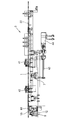
- FIG. 1 is a plan view showing an entire coil winding device according to the present invention.
- FIG. 2 is a front view showing the entire winding device.
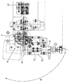
- FIG. 3 is a plan view of the first carriage.
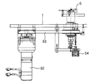
- FIG. 4 is a front view of the shaft body and its peripheral mechanism.
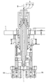
- FIG. 5 is a cross-sectional view of the shaft body.
- FIG. 6 is a plan view of the shaft body and its peripheral mechanism.
- FIG. 7 is a front view of the bending mechanism.
- FIG. 8 is a perspective view of the shaft body and the bending mechanism.
- FIG. 9 is a perspective view for explaining the operation of the shaft body.
- FIG. 10 is a cross-sectional view illustrating the dimensional relationship between the shaft body and the coil intermediate product.
- FIG. 10 is a cross-sectional view illustrating the dimensional relationship between the shaft body and the coil intermediate product.
- FIG. 11 is an enlarged plan view showing a corner of the coil intermediate product.
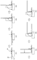
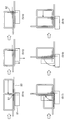
- FIG. 12 is a series of plan views for explaining the first stage of the coil winding process.
- FIG. 13 is a series of plan views for explaining the second stage of the coil winding process.
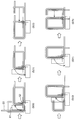
- FIG. 14 is a series of plan views for explaining the third stage of the coil winding process.
- FIG. 15 is a series of plan views for explaining the fourth stage of the coil winding process.
- FIG. 16 is a series of plan views for explaining the fifth stage of the coil winding process.
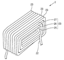
- FIG. 17 is a perspective view of the completed state of the coil.
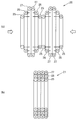
- FIG. 18 is a diagram illustrating a compression process for obtaining a finished product from an intermediate coil product.
- the lead wire (22) is transferred from right to left along a straight line on a horizontal plane.
- the winding device has a first carriage (slidable in the front-rear direction perpendicular to the transition path of the conductor (22) on a base (1) having a horizontal surface. 11) is provided, and on the left side of the first carriage (11), the shaft body (5) projecting vertically upward and the shaft body (5) can be rotated in an angular range exceeding 90 degrees.
- a rotating table (12) is provided.
- a second carriage (13) capable of sliding in the front-rear direction at the initial position of the turntable (12) shown in FIG.
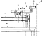
- a pressing member (61) capable of pressing the conducting wire (22) is attached to the end of the shaft (5) as shown in FIG.
- the first carriage 11 has a pair of reciprocating guide mechanisms 71, 72 at the left and right ends, and is moved back and forth by an arbitrary distance by the first reciprocating drive mechanism 7. I can do it. Further, the second carriage 13 can be moved back and forth by an arbitrary distance by the second reciprocating drive mechanism 8 shown in FIG.
- a motor (62) is linked to the turntable (12) via a belt mechanism (63) shown in FIG. Thereby, the bending mechanism (6) for winding the conducting wire (22) around the outer peripheral surface of the shaft body (5) is configured.
- a lead wire feeding mechanism (3) for feeding the lead wire (22) from the upstream side toward the downstream side is connected to the first carriage (11) at the right end on the upstream side of the lead wire (22). .
- the lead wire transfer mechanism (4) includes a first gripping mechanism (41) and a second gripping mechanism (42).
- a motor (44) is connected to the first gripping mechanism (41) via a shaft (43) shown in FIG. 2, and when the motor (44) is driven, the first gripping mechanism (41) is connected to a lead wire (22). ) Reciprocate along the transition path.
- the first gripping mechanism (41) moves the lead wire (22) according to the moving distance by moving from the downstream position to the upstream side while gripping the lead wire (22), and then grips the lead wire (22). It returns to the original downstream position in a state in which is released.
- the second holding mechanism (42) releases the holding of the conducting wire (22) during the holding period of the conducting wire (22) by the first holding mechanism (41) and holds the conducting wire (22) by the first holding mechanism (41). During the release, the conductor (22) is gripped.
- the shaft body (5) is disposed along the transition path of the conducting wire (22). As shown in FIG. 5, the shaft body (5) is coaxial with the winding shaft S as a center, and has a round shaft-shaped first shaft portion (51). And a cylindrical second shaft portion (52) and a cylindrical third shaft portion (53).
- the first shaft portion (51) is connected to the first reciprocating drive mechanism (54) shown in FIG.
- the second shaft portion (52) and the third shaft portion (53) are respectively connected to the second reciprocating drive mechanism (55) and the third reciprocating drive mechanism (56) shown in FIG.
- the second shaft portion (52) of the shaft body (5) has an outer diameter obtained by adding twice the outer diameter of the conducting wire to the outer diameter of the first shaft portion (51).
- the third shaft portion (53) has an outer diameter obtained by adding twice the outer diameter of the conducting wire to the outer diameter of the second shaft portion (52).
- the turntable (12) constituting the bending mechanism (6) reciprocates along a circumferential line R around the winding axis S of the conducting wire.
- the second carriage 13 on the turntable 12 reciprocates along a linear path P that approaches and separates from the winding axis S of the conducting wire. Accordingly, the pressing member (61) constituting the bending mechanism (6) approaches and separates from the shaft body (5) and rotates around the shaft body (5).
- the pressing member (61) is formed with a concave groove (60) extending along the transition path of the conducting wire (22). Further, a U-shaped guide plate (9) is installed in the vicinity of the shaft body (5).
- the first carriage (11) moves forward so that the lead wire (22) is connected to the first shaft portion (51) of the shaft body (5), While moving parallel to the position along the outer peripheral surface of the biaxial portion (52) or the third axial portion (53), the second carriage (13) moves forward so that the pressing member (61) moves the conductive wire (22).
- the conducting wire (22) is transferred by a predetermined distance.
- the transfer distance of the conducting wire (22) is set to a size corresponding to the length of each of the four sides of the unit winding portion to be formed.
- the pressing member (61) is rotated by a predetermined rotation angle ⁇ exceeding 90 degrees from the initial position along the conducting wire (22), whereby the conducting wire (22) is turned into the first shaft portion of the shaft body (5). (51) It is bent by 90 degrees along the outer peripheral surface of the second shaft portion (52) or the third shaft portion (53).
- the rotation angle ⁇ of the pressing member (61) is slightly larger than 90 degrees, the conductor (22) has a bending angle of 90 degrees due to the spring back.
- the conducting wire (22) extending beyond the shaft body (5) slides along the surface of the guide plate (9).
- the guide plate (9) has an inclination angle corresponding to the lead angle of the unit winding portion, and the conductive wire (22) slides along the surface of the guide plate (9). A predetermined lead angle is given to the conducting wire (22).
- One unit winding part having four arcuate corners is formed by repeating the transfer process and bending process of the conducting wire (22) described above four times. Then, the shaft portion of the shaft body (5) around which the conducting wire (22) is to be wound is changed to another shaft portion having a different outer diameter, and the first carriage (11) and the first shaft are changed according to the outer diameter of the shaft portion. 2 With the carriage (13) moved back and forth, the next unit winding part having four arcuate corners can be obtained by repeating the transfer process and bending process of the conductor (22) four times. It is formed.
- the corners of the first unit winding portion (25) formed by winding the conductive wire around the outer peripheral surface of the first shaft portion (51) of the shaft body (5), and the second shaft portion A corner portion of the second unit winding portion (26) formed by winding a conducting wire around the outer peripheral surface of (52) and a third unit winding portion formed by winding the conducting wire around the outer peripheral surface of the third shaft portion (53)
- the corner of (27) has a common center of curvature coinciding with the winding axis S.
- the first unit winding portion (25), the second unit winding portion (26) and the third unit winding portion (27) are formed into one unit as shown in FIG.
- the coil part (23) an air core coil intermediate product (20) in which the unit coil part (23) is repeatedly formed is obtained.
- step S1 of FIG. 12 the conducting wire (22) is placed along the outer peripheral surface of the first shaft portion (51), and the pressing member (61) is placed along the conducting wire (22).
- step S3 the pressing member (61) is rotated to bend the lead wire (22).
- step S4 the pressing member (61) is returned to the initial position.
- step S5 the conductor (22) is transferred by a predetermined distance (the length of the short side of the unit winding portion), and in step S6, the pressing member (61) is rotated to bend the conductor (22). .
- a second arc-shaped corner portion corresponding to the outer diameter of the first shaft portion (51) is formed.
- step S7 the pressing member (61) is returned to the initial position. Then, in step S8 of FIG. 13, the conductor (22) is transferred by a predetermined distance (the length of the long side of the unit winding portion), and then in step S9, the pressing member (61) is rotated to conduct the conductor (22). Bend. As a result, a third arcuate corner portion corresponding to the outer diameter of the first shaft portion (51) is formed.
- step S10 the pressing member (61) is returned to the initial position.
- step S11 the conductive wire (22) is transferred by a predetermined distance (the length of the short side of the unit winding portion), and in step S12, the pressing member (61) is rotated to bend the conductive wire (22). .
- a fourth arc-shaped corner portion corresponding to the outer diameter of the first shaft portion (51) is formed, and the first unit winding portion (25) is wound.
- step S13 the pressing member (61) is returned to the initial position.
- step S14 in FIG. 14 the conductor (22) is transferred by a predetermined distance (the length of the long side of the unit winding portion), and then in step S15, the first carriage (11) and the second carriage (13 ) Is retracted by a distance corresponding to the outer diameter of the conductor (22).
- step S17 the pressing member (61) is rotated to bend the conducting wire (22). As a result, a first arc-shaped corner portion corresponding to the outer diameter of the second shaft portion (52) is formed.
- step S18 the pressing member (61) is returned to the initial position.
- step S19 the conductor (22) is transferred by a predetermined distance (the length of the short side of the unit winding portion), and then in step S20 of FIG. 15, the pressing member (61) is rotated to thereby conduct the conductor (22). Bend. As a result, a second arc-shaped corner corresponding to the outer diameter of the second shaft portion (52) is formed.
- step S21 the pressing member (61) is returned to the initial position.
- step S22 the conductor (22) is transferred by a predetermined distance (the length of the long side of the unit winding portion), and in step S23, the pressing member (61) is rotated to bend the conductor (22). .
- a third arc-shaped corner corresponding to the outer diameter of the second shaft portion (52) is formed.
- step S24 the pressing member (61) is returned to the initial position.
- step S25 after the conducting wire (22) is transferred by a predetermined distance (the length of the short side of the unit winding portion), in step S26 in FIG. 16, the pressing member (61) is rotated to conduct the conducting wire (22). Bend.
- a fourth arc-shaped corner portion corresponding to the outer diameter of the second shaft portion (52) is formed, and the second unit winding portion (26) is wound.
- step S27 the pressing member (61) is returned to the initial position.
- step S28 the conductor (22) is transferred by a predetermined distance (the length of the long side of the unit winding portion), and then in step S29, the first carriage (11) and the second carriage (13) are connected to the conductor. Retract by a distance corresponding to the outer diameter of (22).
- step S31 the pressing member (61) is rotated to bend the conducting wire (22). As a result, a first arc-shaped corner portion corresponding to the outer diameter of the third shaft portion (53) is formed.
- the third unit winding portion (27) is wound to form the first unit coil portion (23).
- the winding shaft is changed in the order of the third shaft portion (53), the second shaft portion (52), and the first shaft portion (51), and the first carriage (11) and the second carriage (13 ) Is advanced by a distance corresponding to the outer diameter of the conductor (22), and the third unit winding part (27), the second unit winding part (26), and the first unit winding part (25) are wound in this order,
- the air core coil intermediate product (20) shown in FIG. 10 is completed.
- the guide plate (9) shown in FIG. 8 has an inclination angle corresponding to the lead angle of the unit winding portion. Therefore, each time the pressing member (61) is rotated, the guide wire ( 22) is provided with a lead angle, and each time one unit winding is formed, the unit winding is pushed up by one pitch, and the winding of the intermediate product (20) is moved vertically upward as shown in FIG. proceed.
- the intermediate product (20) of the air-core coil obtained as described above is compressed in the direction of the winding axis as shown in FIGS. 18 (a) and 18 (b) to obtain a finished product (21) of the three-layer coil. obtain.
- the second unit winding part (26) is pushed inside the third unit winding part (27), and the first unit winding part (26) is inserted inside the second unit winding part (26). 25) is pushed in.
- the first unit winding part (25) and the second unit constituting each unit coil part are formed in an arc shape in which three corner portions formed at the same phase angle with respect to the winding axis S have the center of curvature at the same position S. . Therefore, the gap between the unit windings at each corner of the coil (2) as a finished product becomes zero, and the space factor of the conducting wire increases.
- the coil (2) as a finished product functions as a reactor with a core (not shown) inserted in the central cavity, or used as a primary or secondary winding of a transformer. become.
- the conducting wire (22) is not limited to a round wire but may be a square wire having a rectangular cross section.
Landscapes
- Engineering & Computer Science (AREA)
- Power Engineering (AREA)
- Manufacturing & Machinery (AREA)
- Mechanical Engineering (AREA)
- Manufacture Of Motors, Generators (AREA)
- Coil Winding Methods And Apparatuses (AREA)
- Coils Of Transformers For General Uses (AREA)
- Manufacturing Cores, Coils, And Magnets (AREA)
- Coiling Of Filamentary Materials In General (AREA)
- Wire Processing (AREA)
Abstract
互いに異なる内周長を有する複数の単位巻部が巻き軸方向に連続して形成されると共に、該複数の単位巻部からなる単位コイル部が巻き軸方向に連続して形成されているコイルを作製することが出来る、簡易な構成の巻線装置を提供する。 本発明に係るコイルの巻線装置は、軸体5と、軸体5に対して交叉する直線の移行路に沿って導線22を移送して、軸体5の外周面に導線22を沿わせる導線移送機構と、導線22を押圧すべき押圧部材61を、軸体5を中心とする円周経路に沿って回動させることにより、導線22を軸体5の外周面に沿って屈曲させる曲げ機構6とを具えている。
Description
本発明は、複数のコイル層からなるコイルの巻線方法及び巻線装置に関するものである。
出願人は、図17に示す如く、導線(22)を渦巻き状に巻回してなる単位コイル部(23)が巻き軸方向に繰り返し並んだコイル(2)を開発している。
この様なコイル(2)の製造方法として、図18(a)の如く、導線を渦巻き状に巻回することにより、互いに異なる内周長を有する第1単位巻部(25)、第2単位巻部(26)及び第3単位巻部(27)を、巻き軸方向に連続して形成すると共に、これら複数の単位巻部(25)(26)(27)からなる単位コイル部を、巻き軸方向に連続して形成して、空芯コイルの中間製品(20)を作製した後、該中間製品(20)を巻き軸方向に圧縮して、図18(b)の如く、第3単位巻部(27)の内側に第2単位巻部(26)の少なくとも一部を押し込み、該第2単位巻部(26)の内側に第1単位巻部(25)の少なくとも一部を押し込むことにより、複数のコイル層(図示する例では3層)からなる空芯コイルの完成品(21)を得る方法が知られている(特許文献1)。
図18(a)に示す空芯コイルの中間製品(20)を作製する方法としては、該中間製品(20)の空洞形状に応じた段付きの巻線治具を用いる方法(特許文献1)や、各単位巻部の巻線工程毎に巻芯部材の形態を変化させつつ該巻芯部材の周囲に導線を巻回する自動巻線機が知られている(特許文献2)。
しかしながら、段付きの巻線治具を用いる方法では、巻線作業が手作業となるため、生産効率が悪い問題がある。
又、各単位巻部の巻線工程毎に巻芯部材の形態を変化させつつ該巻芯部材の周囲に導線を巻回する自動巻線機においては、各単位巻部の巻線工程毎に巻芯部材の形態を変化させるための構成が複雑となる問題がある。
又、各単位巻部の巻線工程毎に巻芯部材の形態を変化させつつ該巻芯部材の周囲に導線を巻回する自動巻線機においては、各単位巻部の巻線工程毎に巻芯部材の形態を変化させるための構成が複雑となる問題がある。
そこで本発明の目的は、簡易な構成で、互いに異なる内周長を有する複数の単位巻部が巻き軸方向に連続して形成されると共に、該複数の単位巻部からなる単位コイル部が巻き軸方向に連続して形成されているコイルを作製することが出来る、コイルの巻線方法及び巻線装置を提供することである。
本発明に係るコイルにおいては、互いに異なる内周長を有する複数の単位巻部が巻き軸方向に連続して形成され、各単位巻部は、それぞれ円弧状の複数の角部を有するループ状の巻き線経路に沿って巻回され、該複数の単位巻部からなる単位コイル部が巻き軸方向に連続して形成されている。
ここで、各単位コイル部を構成する複数の単位巻部は、前記巻き軸に対して同じ位相角度に形成される複数の角部が、同じ位置に曲率中心を有する円弧状に形成されている。
ここで、各単位コイル部を構成する複数の単位巻部は、前記巻き軸に対して同じ位相角度に形成される複数の角部が、同じ位置に曲率中心を有する円弧状に形成されている。
本発明に係るコイルの巻線方法は、互いに異なる内周長を有する複数の単位巻部が巻き軸方向に連続して形成され、各単位巻部は、それぞれ円弧状の複数の角部を有するループ状の巻き線経路に沿って巻回され、該複数の単位巻部からなる単位コイル部が巻き軸方向に連続して形成されているコイルの巻線方法であって、
軸体(5)に対して交叉する直線の移行路に沿って所定距離だけ導線(22)を移送して、軸体(5)の外周面に導線(22)を沿わせる第1工程と、
導線(22)を押圧すべき押圧部材(61)を、軸体(5)を中心とする円周経路に沿って回動させることにより、導線(22)を軸体(5)の外周面に所定角度だけ巻き付けて、円弧状の角部を形成する第2工程
とを有し、第1工程と第2工程を前記角部の数だけ繰り返すことによって1つの単位巻部を形成し、1つの単位巻部を形成する過程で、各角部の形成に際して軸体(5)の外径を変化させることにより、各単位コイル部を構成する複数の単位巻部において、前記巻き軸に対して同じ位相角度に形成される複数の角部を、同じ位置に曲率中心を有すると共に曲率半径の異なる円弧状に形成する。
具体的態様において、前記複数の単位巻部からなる単位コイル部が巻き軸方向に連続して形成されているコイルが作製された後、該コイルを巻き軸方向に圧縮して、各単位コイルを構成する複数の単位巻部の内、内周長の大きな単位巻部の内側に内周長の小さな単位巻部の少なくとも一部を押し込む第3工程を有している。
これによって、各単位コイル部が少なくとも一部で多層化されることになる。
これによって、各単位コイル部が少なくとも一部で多層化されることになる。
本発明に係るコイルの巻線装置は、互いに異なる内周長を有する複数の単位巻部が巻き軸方向に連続して形成され、各単位巻部は、それぞれ円弧状の複数の角部を有するループ状の巻き線経路に沿って巻回され、該複数の単位巻部からなる単位コイル部が巻き軸方向に連続して形成されているコイルの巻線装置であって、
軸体(5)と、
前記軸体(5)に対して交叉する直線の移行路に沿って導線(22)を移送して、軸体(5)の外周面に導線(22)を沿わせる導線移送機構(4)と、
導線(22)を押圧すべき押圧部材(61)を、軸体(5)を中心とする円周経路に沿って回動させることにより、導線(22)を軸体(5)の外周面に沿って屈曲させる曲げ機構(6)
とを具えている。
軸体(5)と、
前記軸体(5)に対して交叉する直線の移行路に沿って導線(22)を移送して、軸体(5)の外周面に導線(22)を沿わせる導線移送機構(4)と、
導線(22)を押圧すべき押圧部材(61)を、軸体(5)を中心とする円周経路に沿って回動させることにより、導線(22)を軸体(5)の外周面に沿って屈曲させる曲げ機構(6)
とを具えている。
具体的態様において、前記軸体(5)は、巻き軸と同心軸上に配備された複数の軸部(51)(52)(53)から構成され、該軸体(5)は、中心の軸部(51)に対して他の軸部(52)(53)をそれぞれ巻き軸に沿って往復移動させる往復駆動機構に繋がっている。
又、他の具体的態様においては、前記軸体(5)を包囲して、曲げ機構(6)によってループ状に屈曲された導線(22)をガイドするガイド板(9)が設置されている
更に具体的な態様において、前記ガイド板(9)の表面は、前記軸体(5)と直交する面に対して単位巻部のリード角度に応じた傾斜を有している。
本発明に係るコイルの巻線方法及び巻線装置によって製造されるコイルによれば、各単位コイル部を構成する複数の単位巻部において、巻き軸に対して同じ位相角度に形成される複数の角部が、同じ位置に曲率中心を有する円弧状に形成されているので、各単位コイル部を少なくとも一部で多層化したとき、多層化部にて、内側の単位巻部と外側の単位巻部との間の隙間が可及的にゼロに近づき、この結果、導線の占積率が増大する。
以下、図18(a)に示す空芯コイルの中間製品(20)を作製するための巻線方法及び巻線装置につき、図面に沿って具体的に説明する。尚、図1において、導線(22)は水平面上を直線に沿って右から左へ移送される。
本発明に係る巻線装置は、図1に示す如く、水平の表面を有するベース(1)上に、導線(22)の移行路に対して直交する前後方向にスライド可能な第1往復台(11)が配備されると共に、第1往復台(11)の左側には、鉛直上方に突出する軸体(5)と、軸体(5)を中心として90度を超える角度範囲で回転が可能な回転台(12)とが配備されている。
回転台(12)上には、図1に示す回転台(12)の初期位置にて前後方向にスライドが可能な第2往復台(13)が配備されている。
第2往復台(13)には、図6に示す如く軸体(5)側の端部に、導線(22)を押圧することが可能な押圧部材(61)が取り付けられている。
第2往復台(13)には、図6に示す如く軸体(5)側の端部に、導線(22)を押圧することが可能な押圧部材(61)が取り付けられている。
第1往復台(11)は、図3に示す如く左右の端部に一対の往復ガイド機構(71)(72)を具え、第1往復駆動機構(7)によって前後に任意距離だけ移動させることが出来る。
又、第2往復台(13)は、図1に示す第2往復駆動機構(8)によって前後に任意距離だけ移動させることが出来る。
回転台(12)には、図4に示すベルト機構(63)を介してモータ(62)が連繋している。
これによって、軸体(5)の外周面に導線(22)を巻き付けるための曲げ機構(6)が構成される。
又、第2往復台(13)は、図1に示す第2往復駆動機構(8)によって前後に任意距離だけ移動させることが出来る。
回転台(12)には、図4に示すベルト機構(63)を介してモータ(62)が連繋している。
これによって、軸体(5)の外周面に導線(22)を巻き付けるための曲げ機構(6)が構成される。
第1往復台(11)には、導線(22)の上流側となる右側の端部に、導線(22)を上流側から下流側へ向けて繰り出す導線繰り出し機構(3)が連結されている。
第1往復台(11)上には、導線(22)の移行路に沿って導線移送機構(4)が配備されている。導線移送機構(4)は、第1把持機構(41)と第2把持機構(42)とを具えている。第1把持機構(41)には、図2に示すシャフト(43)を介してモータ(44)が連結されており、モータ(44)の駆動によって、第1把持機構(41)を導線(22)の移行路に沿って往復移動させる。
第1把持機構(41)は、導線(22)を把持した状態で下流位置から上流側へ移動することによってその移動距離に応じて導線(22)を移送し、その後、導線(22)の把持を解除した状態で元の下流位置へ復帰するものである。
第2把持機構(42)は、第1把持機構(41)による導線(22)の把持期間中は導線(22)の把持を解除し、第1把持機構(41)による導線(22)の把持解除中は導線(22)を把持するものである。
第2把持機構(42)は、第1把持機構(41)による導線(22)の把持期間中は導線(22)の把持を解除し、第1把持機構(41)による導線(22)の把持解除中は導線(22)を把持するものである。
軸体(5)は、導線(22)の移行路に沿って配備されており、図5に示す如く、巻き軸Sを中心として同軸上に、丸軸状の第1軸部(51)と、円筒状の第2軸部(52)と、円筒状の第3軸部(53)とを具え、第1軸部(51)は、図4に示す第1往復駆動機構(54)に繋がり、第2軸部(52)及び第3軸部(53)は、図5に示す第2往復駆動機構(55)及び第3往復駆動機構(56)にそれぞれ繋がっている。
これによって、図9(a)の如く第1軸部(51)のみを突出させた第1状態と、図9(b)の如く第1軸部(51)及び第2軸部(52)を突出させた第2状態と、図9(c)の如く第1軸部(51)、第2軸部(52)及び第3軸部(53)を突出させた第3状態とを実現することが出来る。
図10及び図11に示す如く、軸体(5)の第2軸部(52)は、第1軸部(51)の外径に対して導線の外径の2倍を加算した外径を有し、第3軸部(53)は、第2軸部(52)の外径に対して導線の外径の2倍を加算した外径を有している。
曲げ機構(6)を構成する回転台(12)は、図6及び図8に示す如く、導線の巻き軸Sを中心とする円周線Rに沿って往復移動する。
回転台(12)上の第2往復台(13)は、図7及び図8に示す如く、導線の巻き軸Sに対して接近離間する直線経路Pに沿って往復移動する。
これによって、曲げ機構(6)を構成する押圧部材(61)は、軸体(5)に対して接近離間すると共に、軸体(5)を中心として回動することになる。
回転台(12)上の第2往復台(13)は、図7及び図8に示す如く、導線の巻き軸Sに対して接近離間する直線経路Pに沿って往復移動する。
これによって、曲げ機構(6)を構成する押圧部材(61)は、軸体(5)に対して接近離間すると共に、軸体(5)を中心として回動することになる。
押圧部材(61)には、図8に示す如く、導線(22)の移行路に沿って延びる凹溝(60)が形成されている。
又、軸体(5)の近傍位置には、U字状のガイド板(9)が設置されている。
又、軸体(5)の近傍位置には、U字状のガイド板(9)が設置されている。
上記巻線装置による巻線工程においては、図8に示す如く、第1往復台(11)が前進することによって、導線(22)が軸体(5)の第1軸部(51)、第2軸部(52)若しくは第3軸部(53)の外周面に沿う位置まで平行移動すると共に、第2往復台(13)が前進することによって、押圧部材(61)が導線(22)を押圧することが可能な位置まで前進した状態で、先ず、導線(22)が所定距離だけ移送される。該導線(22)の移送距離は、形成せんとする単位巻部における4辺の各辺の長さに応じた大きさに設定される。
次に、押圧部材(61)が、導線(22)に沿った初期位置から90度を超える所定の回転角度θだけ回転することによって、導線(22)を軸体(5)の第1軸部(51)、第2軸部(52)若しくは第3軸部(53)の外周面に沿わせて90度だけ屈曲させる。
尚、押圧部材(61)の回転角度θを90度よりも僅かに大きく設定することにより、導線(22)はスプリングバックによって90度の屈曲角度を有することになる。
この導線(22)の屈曲過程で、軸体(5)よりも先へ延びている導線(22)は、ガイド板(9)の表面に沿って摺動する。
尚、押圧部材(61)の回転角度θを90度よりも僅かに大きく設定することにより、導線(22)はスプリングバックによって90度の屈曲角度を有することになる。
この導線(22)の屈曲過程で、軸体(5)よりも先へ延びている導線(22)は、ガイド板(9)の表面に沿って摺動する。
ここで、ガイド板(9)は、単位巻部のリード角に応じた傾斜角度を有しており、該ガイド板(9)の表面に沿って導線(22)が摺動することによって、該導線(22)に対して所定のリード角が付与される。
上述の導線(22)の移送工程と折り曲げ工程とを4回繰り返すことによって、4つの円弧状の角部を有する1つの単位巻部が形成される。
そして、導線(22)を巻き付けるべき軸体(5)の軸部を外径の異なる他の軸部に変更すると共に、該軸部の外径に応じて、第1往復台(11)と第2往復台(13)を前後に移動させた状態で、同様に導線(22)の移送工程と折り曲げ工程とを4回繰り返すことによって、4つの円弧状の角部を有する次の単位巻部が形成される。
そして、導線(22)を巻き付けるべき軸体(5)の軸部を外径の異なる他の軸部に変更すると共に、該軸部の外径に応じて、第1往復台(11)と第2往復台(13)を前後に移動させた状態で、同様に導線(22)の移送工程と折り曲げ工程とを4回繰り返すことによって、4つの円弧状の角部を有する次の単位巻部が形成される。
この様にして、内周長の異なる3つの単位巻部が巻回され、これによって1つの単位コイル部が形成される。
ここで、図10に示す如く、第1単位巻部(25)を形成する際には、軸体(5)の第1軸部(51)のみを突出させてその外周面に導線を巻き付け、第2単位巻部(26)を形成する際には、第2軸部(52)を突出させてその外周面に導線を巻き付け、第3単位巻部(27)を形成する際には、第3軸部(53)を突出させてその外周面に導線を巻き付ける。
ここで、図10に示す如く、第1単位巻部(25)を形成する際には、軸体(5)の第1軸部(51)のみを突出させてその外周面に導線を巻き付け、第2単位巻部(26)を形成する際には、第2軸部(52)を突出させてその外周面に導線を巻き付け、第3単位巻部(27)を形成する際には、第3軸部(53)を突出させてその外周面に導線を巻き付ける。
これによって、図11に示す如く、軸体(5)の第1軸部(51)の外周面に導線を巻き付けて形成される第1単位巻部(25)の角部と、第2軸部(52)の外周面に導線を巻き付けて形成される第2単位巻部(26)の角部と、第3軸部(53)の外周面に導線を巻き付けて形成される第3単位巻部(27)の角部とが、巻き軸Sと一致する共通の曲率中心を有することになる。
更に、上述の単位コイル部の形成工程を繰り返すことによって、図10に示す如く第1単位巻部(25)、第2単位巻部(26)及び第3単位巻部(27)を1つの単位コイル部(23)として、該単位コイル部(23)を繰り返し形成した空芯コイルの中間製品(20)が得られることになる。
図12~図16は、本発明に係る巻線装置の一連の動作を表わしている。
図12のステップS1では、導線(22)を第1軸部(51)の外周面に沿わせると共に、該導線(22)に押圧部材(61)を沿わせる。
次に、ステップS2にて導線(22)を所定距離(単位巻部の長辺の長さ)だけ移送した後、ステップS3では、押圧部材(61)を回転させて、導線(22)を屈曲させる。
これによって、第1軸部(51)の外径に応じた1つ目の円弧状の角部が形成されることになる。
図12のステップS1では、導線(22)を第1軸部(51)の外周面に沿わせると共に、該導線(22)に押圧部材(61)を沿わせる。
次に、ステップS2にて導線(22)を所定距離(単位巻部の長辺の長さ)だけ移送した後、ステップS3では、押圧部材(61)を回転させて、導線(22)を屈曲させる。
これによって、第1軸部(51)の外径に応じた1つ目の円弧状の角部が形成されることになる。
次に、ステップS4の如く、押圧部材(61)を初期位置まで復帰させる。そして、ステップS5では、導線(22)を所定距離(単位巻部の短辺の長さ)だけ移送した後、ステップS6では、押圧部材(61)を回転させて、導線(22)を屈曲させる。
これによって、第1軸部(51)の外径に応じた2つ目の円弧状の角部が形成されることになる。
これによって、第1軸部(51)の外径に応じた2つ目の円弧状の角部が形成されることになる。
次に、ステップS7の如く、押圧部材(61)を初期位置まで復帰させる。そして、図13のステップS8では、導線(22)を所定距離(単位巻部の長辺の長さ)だけ移送した後、ステップS9では、押圧部材(61)を回転させて、導線(22)を屈曲させる。
これによって、第1軸部(51)の外径に応じた3つ目の円弧状の角部が形成されることになる。
これによって、第1軸部(51)の外径に応じた3つ目の円弧状の角部が形成されることになる。
続いて、ステップS10の如く、押圧部材(61)を初期位置まで復帰させる。そして、ステップS11では、導線(22)を所定距離(単位巻部の短辺の長さ)だけ移送した後、ステップS12では、押圧部材(61)を回転させて、導線(22)を屈曲させる。
これによって、第1軸部(51)の外径に応じた4つ目の円弧状の角部が形成され、第1単位巻部(25)が巻回されることになる。
これによって、第1軸部(51)の外径に応じた4つ目の円弧状の角部が形成され、第1単位巻部(25)が巻回されることになる。
続いて、ステップS13の如く、押圧部材(61)を初期位置まで復帰させる。そして、図14のステップS14では、導線(22)を所定距離(単位巻部の長辺の長さ)だけ移送した後、ステップS15では、第1往復台(11)と第2往復台(13)を導線(22)の外径に応じた距離だけ後退させる。
次に、ステップS16の如く、第2軸部(52)を上昇させた後、ステップS17では押圧部材(61)を回転させて、導線(22)を屈曲させる。
これによって、第2軸部(52)の外径に応じた1つ目の円弧状の角部が形成されることになる。
次に、ステップS16の如く、第2軸部(52)を上昇させた後、ステップS17では押圧部材(61)を回転させて、導線(22)を屈曲させる。
これによって、第2軸部(52)の外径に応じた1つ目の円弧状の角部が形成されることになる。
続いて、ステップS18の如く、押圧部材(61)を初期位置まで復帰させる。そして、ステップS19では、導線(22)を所定距離(単位巻部の短辺の長さ)だけ移送した後、図15のステップS20では、押圧部材(61)を回転させて、導線(22)を屈曲させる。
これによって、第2軸部(52)の外径に応じた2つ目の円弧状の角部が形成されることになる。
これによって、第2軸部(52)の外径に応じた2つ目の円弧状の角部が形成されることになる。
続いて、ステップS21の如く、押圧部材(61)を初期位置まで復帰させる。そして、ステップS22では、導線(22)を所定距離(単位巻部の長辺の長さ)だけ移送した後、ステップS23では、押圧部材(61)を回転させて、導線(22)を屈曲させる。
これによって、第2軸部(52)の外径に応じた3つ目の円弧状の角部が形成されることになる。
これによって、第2軸部(52)の外径に応じた3つ目の円弧状の角部が形成されることになる。
続いて、ステップS24の如く、押圧部材(61)を初期位置まで復帰させる。そして、ステップS25では、導線(22)を所定距離(単位巻部の短辺の長さ)だけ移送した後、図16のステップS26では、押圧部材(61)を回転させて、導線(22)を屈曲させる。
これによって、第2軸部(52)の外径に応じた4つ目の円弧状の角部が形成され、第2単位巻部(26)が巻回されることになる。
これによって、第2軸部(52)の外径に応じた4つ目の円弧状の角部が形成され、第2単位巻部(26)が巻回されることになる。
続いて、ステップS27の如く、押圧部材(61)を初期位置まで復帰させる。そして、ステップS28では、導線(22)を所定距離(単位巻部の長辺の長さ)だけ移送した後、ステップS29では、第1往復台(11)と第2往復台(13)を導線(22)の外径に応じた距離だけ後退させる。
次に、ステップS30の如く、第3軸部(53)を上昇させた後、ステップS31では押圧部材(61)を回転させて、導線(22)を屈曲させる。
これによって、第3軸部(53)の外径に応じた1つ目の円弧状の角部が形成されることになる。
次に、ステップS30の如く、第3軸部(53)を上昇させた後、ステップS31では押圧部材(61)を回転させて、導線(22)を屈曲させる。
これによって、第3軸部(53)の外径に応じた1つ目の円弧状の角部が形成されることになる。
以後、同様の動作を繰り返すことによって、第3単位巻部(27)が巻回され、1つ目の単位コイル部(23)が形成されることになる。
そして、次は第3軸部(53)、第2軸部(52)、第1軸部(51)の順に巻き付け軸を変更すると共に、第1往復台(11)と第2往復台(13)を導線(22)の外径に応じた距離だけ前進させつつ、第3単位巻部(27)、第2単位巻部(26)、第1単位巻部(25)の順に巻回して、次の単位コイル部(23)を形成し、この単位コイル部(23)の形成を繰り返すことによって、図10に示す空芯コイルの中間製品(20)が完成することになる。
そして、次は第3軸部(53)、第2軸部(52)、第1軸部(51)の順に巻き付け軸を変更すると共に、第1往復台(11)と第2往復台(13)を導線(22)の外径に応じた距離だけ前進させつつ、第3単位巻部(27)、第2単位巻部(26)、第1単位巻部(25)の順に巻回して、次の単位コイル部(23)を形成し、この単位コイル部(23)の形成を繰り返すことによって、図10に示す空芯コイルの中間製品(20)が完成することになる。
上述の巻線装置においては、図8に示すガイド板(9)が、単位巻部のリード角に応じた傾斜角度を有しているので、押圧部材(61)を回動させる度に導線(22)にリード角が付与され、1つの単位巻部が形成される度に該単位巻部が1ピッチだけ押し上げられ、図10に示す如く鉛直上方へ向かって中間製品(20)の巻線が進行する。
上述の様にして得られた空芯コイルの中間製品(20)を、図18(a)(b)に示す様に巻き軸方向に圧縮することによって、3層コイルの完成品(21)を得る。該完成品(21)においては、第3単位巻部(27)の内側に第2単位巻部(26)が押し込まれ、該第2単位巻部(26)の内側に第1単位巻部(25)が押し込まれている。
上記の巻線方法及び巻線装置によって作製された空芯コイルの中間製品(20)においては、図11に示す如く、各単位コイル部を構成する第1単位巻部(25)、第2単位巻部(26)及び第3単位巻部(27)は、巻き軸Sに対して同じ位相角度に形成される3つの角部が、同じ位置Sに曲率中心を有する円弧状に形成されている。
従って、完成品としてのコイル(2)の各角部における単位巻部間の隙間がゼロとなり、導線の占積率が増大することになる。
従って、完成品としてのコイル(2)の各角部における単位巻部間の隙間がゼロとなり、導線の占積率が増大することになる。
完成品としてのコイル(2)は、その中央空洞部にコア(図示省略)が挿入された状態で、リアクトルとして機能し、或いは、変圧器の一次巻線若しくは二次巻線として使用されることになる。
尚、本発明の各部構成は上記実施の形態に限らず、特許請求の範囲に記載の技術的範囲内で種々の変形が可能である。例えば、導線(22)は丸線に限らず、断面矩形の角線であってもよい。
(2) コイル
(20) 中間製品
(21) 完成品
(22) 導線
(23) 単位コイル部
(25) 第1単位巻部
(26) 第2単位巻部
(27) 第3単位巻部
(1) ベース
(11) 第1往復台
(12) 回転台
(13) 第2往復台
(3) 導線繰り出し機構
(4) 導線移送機構
(5) 軸体
(51) 第1軸部
(52) 第2軸部
(53) 第3軸部
(6) 曲げ機構
(61) 押圧部材
(62) モータ
(7) 第1往復駆動機構
(8) 第2往復駆動機構
(9) ガイド板
S 巻き軸
(20) 中間製品
(21) 完成品
(22) 導線
(23) 単位コイル部
(25) 第1単位巻部
(26) 第2単位巻部
(27) 第3単位巻部
(1) ベース
(11) 第1往復台
(12) 回転台
(13) 第2往復台
(3) 導線繰り出し機構
(4) 導線移送機構
(5) 軸体
(51) 第1軸部
(52) 第2軸部
(53) 第3軸部
(6) 曲げ機構
(61) 押圧部材
(62) モータ
(7) 第1往復駆動機構
(8) 第2往復駆動機構
(9) ガイド板
S 巻き軸
Claims (9)
- 互いに異なる内周長を有する複数の単位巻部が巻き軸方向に連続して形成され、各単位巻部は、それぞれ円弧状の複数の角部を有するループ状の巻き線経路に沿って巻回され、該複数の単位巻部からなる単位コイル部が巻き軸方向に連続して形成されているコイルにおいて、
各単位コイル部を構成する複数の単位巻部は、前記巻き軸に対して同じ位相角度に形成される複数の角部が、同じ位置に曲率中心を有する円弧状に形成されていることを特徴とするコイル。 - 互いに異なる内周長を有する複数の単位巻部が巻き軸方向に連続して形成され、各単位巻部は、それぞれ円弧状の複数の角部を有するループ状の巻き線経路に沿って巻回され、該複数の単位巻部からなる単位コイル部が巻き軸方向に連続して形成されているコイルの巻線方法において、
軸体に対して交叉する直線の移行路に沿って所定距離だけ導線を移送して、軸体の外周面に導線を沿わせる第1工程と、
導線を押圧すべき押圧部材を、軸体を中心とする円周経路に沿って回動させることにより、導線を軸体の外周面に巻き付けて、円弧状の角部を形成する第2工程
とを有し、第1工程と第2工程を前記角部の数だけ繰り返すことによって1つの単位巻部を形成し、1つの単位巻部を形成する過程で、各角部の形成に際して軸体の外径を変化させることにより、各単位コイル部を構成する複数の単位巻部において、前記巻き軸に対して同じ位相角度に形成される複数の角部を、同じ位置に曲率中心を有する円弧状に形成することを特徴とするコイルの巻線方法。 - 前記軸体は、巻き軸と同心軸上に配備された複数の軸部から構成され、中心の軸部に対して他の軸部を昇降させることによって、該軸体の外径を変化させる請求項2に記載のコイルの巻線方法。
- 前記複数の単位巻部からなる単位コイル部が巻き軸方向に連続して形成されているコイルを作製した後、巻き軸方向の両側から圧縮力を加えることによって、各単位コイル部を構成する複数の単位巻部の内、内周長の大きな単位巻部の内側に内周長の小さな単位巻部の少なくとも一部を押し込む第3工程を有している請求項2又は請求項3に記載のコイルの巻線方法。
- 互いに異なる内周長を有する複数の単位巻部が巻き軸方向に連続して形成され、各単位巻部は、それぞれ円弧状の複数の角部を有するループ状の巻き線経路に沿って巻回され、該複数の単位巻部からなる単位コイル部が巻き軸方向に連続して形成されているコイルの巻線装置において、
軸体と、
前記軸体に対して交叉する直線の移行路に沿って導線を移送して、軸体の外周面に導線を沿わせる導線移送機構と、
導線を押圧すべき押圧部材を、軸体を中心とする円周経路に沿って回動させることにより、導線を軸体の外周面に沿って屈曲させる曲げ機構
とを具えていることを特徴とするコイルの巻線装置。 - 前記軸体は、巻き軸と同心軸上に配備された複数の軸部から構成され、該軸体は、中心の軸部に対して他の軸部をそれぞれ巻き軸に沿って往復させる往復駆動機構に繋がっている請求項5に記載のコイルの巻線装置。
- 前記導線移送機構は、軸体と直交する方向に前後移動する第1往復台上に配備され、前記曲げ機構は、前記軸体を中心として回転する回転台と、該回転台上に設けられて前記軸体と直交する方向に前後移動する第2往復台とを具え、該第2往復台上に前記押圧部材が取り付けられている請求項5又は請求項6に記載のコイルの巻線装置。
- 前記軸体を包囲して、曲げ機構によってループ状に屈曲された導線の回動をガイドするガイド板が設置されている請求項5乃至請求項7の何れかに記載のコイルの巻線装置。
- 前記ガイド板の表面は、前記軸体と直交する面に対して単位巻部のリード角度に応じた傾斜を有している請求項8に記載のコイルの巻線装置。
Priority Applications (5)
| Application Number | Priority Date | Filing Date | Title |
|---|---|---|---|
| KR1020187024382A KR101948499B1 (ko) | 2011-07-08 | 2012-06-27 | 코일의 권선 방법 및 권선 장치 |
| KR1020147000739A KR101910225B1 (ko) | 2011-07-08 | 2012-06-27 | 코일의 권선 방법 및 권선 장치 |
| CN201280033950.3A CN103843088B (zh) | 2011-07-08 | 2012-06-27 | 线圈的绕线方法及绕线装置 |
| US14/149,778 US20140184379A1 (en) | 2011-07-08 | 2014-01-07 | Coil winding method and winding apparatus |
| US15/268,358 US10418173B2 (en) | 2011-07-08 | 2016-09-16 | Coil winding method and winding apparatus |
Applications Claiming Priority (2)
| Application Number | Priority Date | Filing Date | Title |
|---|---|---|---|
| JP2011-151444 | 2011-07-08 | ||
| JP2011151444A JP5535141B2 (ja) | 2011-07-08 | 2011-07-08 | 空芯コイルの巻線方法及び巻線装置 |
Related Child Applications (1)
| Application Number | Title | Priority Date | Filing Date |
|---|---|---|---|
| US14/149,778 Continuation US20140184379A1 (en) | 2011-07-08 | 2014-01-07 | Coil winding method and winding apparatus |
Publications (1)
| Publication Number | Publication Date |
|---|---|
| WO2013008621A1 true WO2013008621A1 (ja) | 2013-01-17 |
Family
ID=47505918
Family Applications (1)
| Application Number | Title | Priority Date | Filing Date |
|---|---|---|---|
| PCT/JP2012/066327 WO2013008621A1 (ja) | 2011-07-08 | 2012-06-27 | コイルの巻線方法及び巻線装置 |
Country Status (6)
| Country | Link |
|---|---|
| US (2) | US20140184379A1 (ja) |
| JP (1) | JP5535141B2 (ja) |
| KR (2) | KR101948499B1 (ja) |
| CN (1) | CN103843088B (ja) |
| TW (1) | TWI552177B (ja) |
| WO (1) | WO2013008621A1 (ja) |
Cited By (1)
| Publication number | Priority date | Publication date | Assignee | Title |
|---|---|---|---|---|
| CN104347263A (zh) * | 2013-07-25 | 2015-02-11 | 安徽一变变压器制造有限公司 | 壳式变压器绕线机 |
Families Citing this family (4)
| Publication number | Priority date | Publication date | Assignee | Title |
|---|---|---|---|---|
| JP5490186B2 (ja) * | 2012-05-31 | 2014-05-14 | 株式会社エス・エッチ・ティ | コイルの巻線方法及び変圧器 |
| JP5499349B2 (ja) * | 2012-11-02 | 2014-05-21 | 福井県 | 巻線構造及びそれを用いた電気機器 |
| WO2015155899A1 (ja) * | 2014-04-12 | 2015-10-15 | 福井県 | 巻線構造及びそれを用いた電気機器 |
| CN110310821A (zh) * | 2019-07-22 | 2019-10-08 | 成都玖锦科技有限公司 | 一种微型精密金丝线圈绕制装置 |
Citations (3)
| Publication number | Priority date | Publication date | Assignee | Title |
|---|---|---|---|---|
| JP2006288025A (ja) * | 2005-03-31 | 2006-10-19 | San-Ei Electronic Industries Co Ltd | 矩形状コイル、矩形状コイルの製造方法及び矩形状コイルの製造装置 |
| JP2006339407A (ja) * | 2005-06-02 | 2006-12-14 | Sht Corp Ltd | 自動巻線機及びこれを用いた空心コイルの製造方法 |
| JP2009302245A (ja) * | 2008-06-12 | 2009-12-24 | Nittoku Eng Co Ltd | エッジワイズコイルの巻線方法及び巻線装置 |
Family Cites Families (10)
| Publication number | Priority date | Publication date | Assignee | Title |
|---|---|---|---|---|
| US3787766A (en) * | 1972-02-22 | 1974-01-22 | Duncan Electric Co Inc | Meter magnet with strip-wound current coil |
| US3989200A (en) * | 1975-04-22 | 1976-11-02 | Bachi, Inc. | Non-circular perfect layer electrical coils |
| US4924201A (en) * | 1988-08-29 | 1990-05-08 | General Electric Company | Core and coil assembly for a transformer having an amorphous steel core |
| JPH07183152A (ja) * | 1993-12-22 | 1995-07-21 | Toshiba Corp | コイル巻線装置 |
| CN1258782C (zh) * | 2001-07-03 | 2006-06-07 | Sht有限公司 | 线圈装置的制造方法 |
| JP3545390B2 (ja) * | 2001-07-03 | 2004-07-21 | 株式会社エス・エッチ・ティ | 空芯コイル、コイル装置及びそれらの製造方法 |
| JP3621676B2 (ja) * | 2001-11-29 | 2005-02-16 | 昭和電線電纜株式会社 | 電気コイルの巻線加工装置 |
| US7317372B2 (en) | 2002-06-11 | 2008-01-08 | Sht Corporation Limited | Air-core coil and process for fabricating the same |
| JP5155732B2 (ja) * | 2008-05-15 | 2013-03-06 | 株式会社日立産機システム | 変圧器用多段コイル、並びにそれを製作するための巻線方法及び装置 |
| JP5935478B2 (ja) * | 2012-04-19 | 2016-06-15 | 株式会社豊田自動織機 | コイル巻取り装置の芯金 |
-
2011
- 2011-07-08 JP JP2011151444A patent/JP5535141B2/ja active Active
-
2012
- 2012-06-27 KR KR1020187024382A patent/KR101948499B1/ko active IP Right Grant
- 2012-06-27 WO PCT/JP2012/066327 patent/WO2013008621A1/ja active Application Filing
- 2012-06-27 CN CN201280033950.3A patent/CN103843088B/zh active Active
- 2012-06-27 KR KR1020147000739A patent/KR101910225B1/ko active IP Right Grant
- 2012-07-03 TW TW101123852A patent/TWI552177B/zh active
-
2014
- 2014-01-07 US US14/149,778 patent/US20140184379A1/en not_active Abandoned
-
2016
- 2016-09-16 US US15/268,358 patent/US10418173B2/en active Active
Patent Citations (3)
| Publication number | Priority date | Publication date | Assignee | Title |
|---|---|---|---|---|
| JP2006288025A (ja) * | 2005-03-31 | 2006-10-19 | San-Ei Electronic Industries Co Ltd | 矩形状コイル、矩形状コイルの製造方法及び矩形状コイルの製造装置 |
| JP2006339407A (ja) * | 2005-06-02 | 2006-12-14 | Sht Corp Ltd | 自動巻線機及びこれを用いた空心コイルの製造方法 |
| JP2009302245A (ja) * | 2008-06-12 | 2009-12-24 | Nittoku Eng Co Ltd | エッジワイズコイルの巻線方法及び巻線装置 |
Cited By (1)
| Publication number | Priority date | Publication date | Assignee | Title |
|---|---|---|---|---|
| CN104347263A (zh) * | 2013-07-25 | 2015-02-11 | 安徽一变变压器制造有限公司 | 壳式变压器绕线机 |
Also Published As
| Publication number | Publication date |
|---|---|
| US20140184379A1 (en) | 2014-07-03 |
| KR101948499B1 (ko) | 2019-02-14 |
| TW201308375A (zh) | 2013-02-16 |
| CN103843088B (zh) | 2016-08-31 |
| US20170069424A1 (en) | 2017-03-09 |
| KR20140037211A (ko) | 2014-03-26 |
| KR20180098689A (ko) | 2018-09-04 |
| JP2013021041A (ja) | 2013-01-31 |
| TWI552177B (zh) | 2016-10-01 |
| KR101910225B1 (ko) | 2018-10-19 |
| JP5535141B2 (ja) | 2014-07-02 |
| US10418173B2 (en) | 2019-09-17 |
| CN103843088A (zh) | 2014-06-04 |
Similar Documents
| Publication | Publication Date | Title |
|---|---|---|
| US10418173B2 (en) | Coil winding method and winding apparatus | |
| US9287042B2 (en) | Winding device and winding method for edgewise coil | |
| US8225491B2 (en) | Coil manufacturing method | |
| WO2011111682A1 (ja) | 回転電機のステータ、ステータの製造方法、及びステータにおけるコイル製造方法 | |
| KR101715991B1 (ko) | 자동 권선기, 공심 코일 및 그 권선 방법 | |
| JP5785117B2 (ja) | 巻線装置および巻線方法 | |
| JP2012151996A (ja) | コイルセグメント環状配列方法、コイルセグメント環状配列装置、及びステータ | |
| US9242830B2 (en) | Coil winding method and transformer | |
| JP2019195845A (ja) | コイル成形装置およびコイル成形方法 | |
| JP2013021041A5 (ja) | ||
| JP5369160B2 (ja) | 空芯コイルの巻線装置 | |
| JP2009262210A (ja) | 長尺素材折曲げ装置および長尺素材折り曲げ方法 | |
| JP6476472B2 (ja) | 巻線装置 | |
| JP5244223B2 (ja) | 空芯コイル及びその巻線方法 | |
| JP5146778B2 (ja) | 線材成形装置及びコイル製造装置 | |
| JP2016092028A (ja) | 巻線装置 | |
| JP2011083789A (ja) | 回転電機の固定子又は回転子のコイル成形装置 | |
| CN111525760A (zh) | 电机绕组线圈的绕制工艺和电机绕组线圈 |
Legal Events
| Date | Code | Title | Description |
|---|---|---|---|
| 121 | Ep: the epo has been informed by wipo that ep was designated in this application |
Ref document number: 12810819 Country of ref document: EP Kind code of ref document: A1 |
|
| DPE1 | Request for preliminary examination filed after expiration of 19th month from priority date (pct application filed from 20040101) | ||
| NENP | Non-entry into the national phase |
Ref country code: DE |
|
| ENP | Entry into the national phase |
Ref document number: 20147000739 Country of ref document: KR Kind code of ref document: A |
|
| 122 | Ep: pct application non-entry in european phase |
Ref document number: 12810819 Country of ref document: EP Kind code of ref document: A1 |