WO2013008469A1 - 鉄道車両用台車 - Google Patents
鉄道車両用台車 Download PDFInfo
- Publication number
- WO2013008469A1 WO2013008469A1 PCT/JP2012/004514 JP2012004514W WO2013008469A1 WO 2013008469 A1 WO2013008469 A1 WO 2013008469A1 JP 2012004514 W JP2012004514 W JP 2012004514W WO 2013008469 A1 WO2013008469 A1 WO 2013008469A1
- Authority
- WO
- WIPO (PCT)
- Prior art keywords
- leaf spring
- vehicle
- axle box
- lateral
- axle
- Prior art date
- Legal status (The legal status is an assumption and is not a legal conclusion. Google has not performed a legal analysis and makes no representation as to the accuracy of the status listed.)
- Ceased
Links
Images


Classifications
-
- B—PERFORMING OPERATIONS; TRANSPORTING
- B61—RAILWAYS
- B61F—RAIL VEHICLE SUSPENSIONS, e.g. UNDERFRAMES, BOGIES OR ARRANGEMENTS OF WHEEL AXLES; RAIL VEHICLES FOR USE ON TRACKS OF DIFFERENT WIDTH; PREVENTING DERAILING OF RAIL VEHICLES; WHEEL GUARDS, OBSTRUCTION REMOVERS OR THE LIKE FOR RAIL VEHICLES
- B61F5/00—Constructional details of bogies; Connections between bogies and vehicle underframes; Arrangements or devices for adjusting or allowing self-adjustment of wheel axles or bogies when rounding curves
- B61F5/26—Mounting or securing axle-boxes in vehicle or bogie underframes
- B61F5/30—Axle-boxes mounted for movement under spring control in vehicle or bogie underframes
-
- B—PERFORMING OPERATIONS; TRANSPORTING
- B61—RAILWAYS
- B61F—RAIL VEHICLE SUSPENSIONS, e.g. UNDERFRAMES, BOGIES OR ARRANGEMENTS OF WHEEL AXLES; RAIL VEHICLES FOR USE ON TRACKS OF DIFFERENT WIDTH; PREVENTING DERAILING OF RAIL VEHICLES; WHEEL GUARDS, OBSTRUCTION REMOVERS OR THE LIKE FOR RAIL VEHICLES
- B61F5/00—Constructional details of bogies; Connections between bogies and vehicle underframes; Arrangements or devices for adjusting or allowing self-adjustment of wheel axles or bogies when rounding curves
- B61F5/26—Mounting or securing axle-boxes in vehicle or bogie underframes
- B61F5/30—Axle-boxes mounted for movement under spring control in vehicle or bogie underframes
- B61F5/301—Axle-boxes mounted for movement under spring control in vehicle or bogie underframes incorporating metal springs
- B61F5/302—Leaf springs
-
- B—PERFORMING OPERATIONS; TRANSPORTING
- B61—RAILWAYS
- B61F—RAIL VEHICLE SUSPENSIONS, e.g. UNDERFRAMES, BOGIES OR ARRANGEMENTS OF WHEEL AXLES; RAIL VEHICLES FOR USE ON TRACKS OF DIFFERENT WIDTH; PREVENTING DERAILING OF RAIL VEHICLES; WHEEL GUARDS, OBSTRUCTION REMOVERS OR THE LIKE FOR RAIL VEHICLES
- B61F5/00—Constructional details of bogies; Connections between bogies and vehicle underframes; Arrangements or devices for adjusting or allowing self-adjustment of wheel axles or bogies when rounding curves
- B61F5/50—Other details
- B61F5/52—Bogie frames
Definitions
- the present invention relates to a railcar bogie that omits side beams.
- Patent Document 1 proposes an axle box support device, in which a carriage frame includes a lateral beam extending in the lateral direction and a pair of left and right side beams extending in the front-rear direction from both ends of the lateral beam.
- the axle box support device includes an axle spring composed of a coil spring interposed between the axle box and a side beam located above the axle box.
- Patent Document 2 proposes a bogie that omits the side beam portion of the bogie frame.
- the bogie frame composed of side beams and side beams is manufactured by welding heavy steel materials to each other, so that the weight of the bogie frame increases, and the steel material cost and There is a problem that the assembly cost becomes high.
- the horizontal beam of the bogie frame and the axle box are connected to each other by a support mechanism member so as to maintain a certain distance from each other, and the front and rear of the leaf spring are disposed at both lateral ends of the horizontal beam.
- a central portion in the direction is held and fixed, and both end portions in the front-rear direction of the leaf spring are inserted into spring receivers provided at the lower portion of the axle box.
- an object of the present invention is to improve the reliability of the leaf spring carriage by allowing the transverse spring to be properly supported even if the leaf spring is damaged.
- a railcar bogie comprises a pair of front and rear axles arranged along the vehicle width direction at the front and rear in the longitudinal direction of the vehicle across the horizontal beam for supporting the body of the railcar.
- a bearing that is provided on both sides of the axle in the vehicle width direction and rotatably supports the axle, a shaft box that accommodates the bearing, and a vehicle longitudinal direction in a state in which both ends of the side wall in the vehicle width direction are supported.
- at least one of the end portions in the vehicle width direction of the transverse beam has a predetermined elastic deformation range of the leaf spring.
- a preliminary support mechanism that supports the end portion of the side beam when displaced downward.
- the preliminary support mechanism when the leaf spring is damaged by any chance, and the lateral end of the lateral beam is displaced downward beyond the predetermined elastic deformation range of the leaf spring, the preliminary support mechanism is moved to the end of the lateral beam. Since the portion is supported, the required support function can be secured by the preliminary support mechanism. Therefore, even if the leaf spring should be damaged, the lateral beam can be properly supported, and the reliability of the leaf spring carriage can be improved.
- the lateral beam can be properly supported, and the reliability of the leaf spring carriage can be improved.
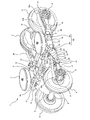
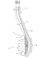
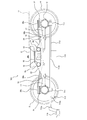
- FIG. 1 is a perspective view showing a railway vehicle carriage according to a first embodiment of the present invention. It is a top view of the trolley
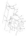
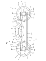
- FIG. 2 is a perspective view showing a receiving seat of the coupling mechanism shown in FIG. 1 and its vicinity.
- FIG. 5 is a cross-sectional view of a main part showing a cross beam, a leaf spring, and a preliminary support member in a cross section taken along line VV in FIG. 2.
- FIG. 6 is a sectional view taken along line VI-VI in FIG. 2. It is a principal part side view showing the leaf
- FIG. 1 is a perspective view showing a railway vehicle carriage 1 according to a first embodiment of the present invention.
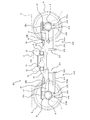
- FIG. 2 is a plan view of the carriage 1 shown in FIG.
- FIG. 3 is a side view of the carriage 1 shown in FIG.
- FIG. 4 is a perspective view showing the receiving seats 21 and 21 of the coupling mechanism 16 shown in FIG. 1 and the vicinity thereof.
- a railcar bogie 1 is arranged in a vehicle width direction (hereinafter also referred to as a lateral direction) as a bogie frame 3 for supporting a vehicle body 11 via an air spring 2 serving as a secondary suspension.
- the lateral beam 4 is not provided with a lateral beam extending from both lateral ends of the lateral beam 4 in the vehicle longitudinal direction (hereinafter also referred to as the front-rear direction).
- a pair of front and rear axles 5 is disposed along the lateral direction in front and rear of the lateral beam 4, and wheels 6 are fixed to both lateral sides of the axle 5.
- Bearings 7 that rotatably support the axle 5 are provided at both lateral ends of the axle 5 so as to be laterally outer than the wheels 6, and the bearings 7 are accommodated in an axle box 8.
- An electric motor 9 is attached to the side beam 4, and a gear box 10 in which a reduction gear for transmitting power to the axle 5 is accommodated is connected to the output shaft of the electric motor 9.
- the side cover 4 is also provided with a brake device (not shown) for braking the rotation of the wheels 6.
- the lateral beam 4 includes a pair of square pipes 12 made of metal extending in the lateral direction and connection plates 13 and 14 made of metal for connecting the square pipes 12.
- the connection plates 13 and 14 are connected to the square pipe 12. On the other hand, it is fixed by bolting or the like.
- a pair of cylindrical connecting plates 14 are provided at both ends 4 a in the lateral direction of the lateral beam 4 at intervals, and an air spring base 15 is installed on the upper surface thereof.
- Both lateral ends 4 a of the lateral beam 4 are coupled to the axle box 8 by a coupling mechanism 16.
- the coupling mechanism 16 includes a shaft beam 17 that extends integrally from the axle box 8 along the front-rear direction.
- the end portion of the shaft beam 17 is provided with a cylindrical portion 18 whose inner peripheral surface is cylindrical and whose both lateral sides are open.
- a mandrel 20 is inserted into the internal space of the cylindrical portion 18 via a rubber bush (not shown).
- a pair of receiving seats 21 and 22 constituting the coupling mechanism 16 are provided in the lateral end portions 4 a of the lateral beam 4 so as to protrude in the front-rear direction.
- the upper ends of the pair of receiving seats 21 and 22 are connected by an upper connecting plate 23, and the upper connecting plate 23 is fixed to the square pipe 12 by a bolt 24.
- the receiving seats 21 and 22 are connected to each other by a lower connecting plate 28 at the projecting tip side of the lower end portion.
- the receiving seats 21 and 22 are formed with insertion grooves 25 that open downward.
- the both ends of the mandrel 20 in the horizontal direction are fitted into the fitting groove 25 from below.
- the lid member 26 is fixed to the receiving seats 21 and 22 by bolts (not shown) so as to close the lower opening of the fitting groove 25, and the mandrel 20 is supported from below by the lid member 26. Yes.
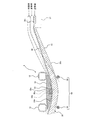
- a leaf spring 30 extending in the front-rear direction is spanned between the side beam 4 and the axle box 8, and a center portion 30 a in the front-rear direction of the plate spring 30 supports both end portions 4 a in the lateral direction of the side beam 4.
- the front and rear direction end portions 30c of the leaf spring 30 are supported by the axle box 8. That is, the leaf spring 30 has both the function of the primary suspension and the function of the conventional side beam.
- a spring seat 31 is attached to the upper end portion of the axle box 8, and both longitudinal end portions 30 c of the leaf spring 30 are supported by the spring seat 31 from below.
- the center part 30a in the front-rear direction of the leaf spring 30 is arranged so as to sink under the lateral beam 4, and contact members 33 (see FIG. 5) provided at both lateral ends 4a of the lateral beam 4 are placed from above. It has been.
- the extension part 30b between the front-rear direction center part 30a and the front-rear direction both end parts 30c of the leaf spring 30 is inclined downward toward the front-rear direction center part 30a in a side view. That is, the front-rear direction center portion 30 a of the leaf spring 30 is located below the front-rear direction end portions 30 c of the leaf spring 30.
- a part of the extending portion 30b of the leaf spring 30 is disposed at a position overlapping the coupling mechanism 16 in a side view while maintaining a state where a gap is formed with the coupling mechanism 16.
- a part of the extended portion 30b of the leaf spring 30 passes below the upper connecting plate 23 and above the lower connecting plate 28 in the space 27 sandwiched between the pair of receiving seats 21 and 22.
- a central portion 30a in the front-rear direction of the leaf spring 30 is located in a space below the lateral beam 4 and above a first preliminary support member 29 described later.
- FIG. 5 is a cross-sectional view of the main part showing the cross beam 4, the leaf spring 30, and the first preliminary support member 29 in the VV line cross section of FIG. 2.
- 6 is a cross-sectional view taken along line VI-VI in FIG.
- a fixing plate 32 made of metal (for example, general steel material) fixed to the lower surfaces of the pair of square pipes 12, and the fixing plate 32.
- a contact member 33 made of a rigid body (for example, metal, fiber reinforced resin, etc.) fixed to the lower surface of the plate spring 30 is provided, and the contact member 33 does not support the lower surface of the plate spring 30. It is placed on the front-rear direction center part 30a from above and is in free contact. In other words, the contact member 33 is in contact with the upper surface of the leaf spring 30 without fixing the leaf spring 30 in the vertical direction.
- the front and rear direction end portions 30 c of the leaf spring 30 are located higher than the contact surface 33 a that is the lower surface of the contact member 33 of the side beam 4.
- a contact surface 33a of the contact member 33 with the leaf spring 30 has a substantially arc shape that protrudes downward in a side view. In a side view, the curvature of the contact surface 33 a of the contact member 33 is set to be larger than the curvature of the portion of the leaf spring 30 that contacts the contact member 33 in a state where the cart 1 does not support the vehicle body 11. ing.
- the leaf spring 30 In the state where the carriage 1 supports the vehicle body 11, the leaf spring 30 is elastically deformed so that the lateral beam 4 sinks downward due to the downward load from the vehicle body 11, and the curvature of the portion of the leaf spring 30 that contacts the contact member 33 is curved.
- the curvature of the contact surface 33a of the contact member 33 is kept larger than the curvature of the portion of the leaf spring 30 that contacts the contact member 33 (solid line in FIG. 5).
- the curvature of the portion of the leaf spring 30 that contacts the contact member 33 increases (broken line in FIG. 5).
- the leaf spring 30 has a two-layer structure including a lower layer portion 35 made of a fiber reinforced resin (for example, CFRP or GFRP) and an upper layer portion 36 made of a metal (for example, a general steel material) thinner than the lower layer portion 35.
- the leaf spring 30 is formed by integrally covering the upper surface side of the leaf spring main body portion (lower layer portion 35) made of fiber reinforced resin with metal (upper layer portion 36).
- the extending portion 30b of the leaf spring 30 is formed so that the thickness T gradually increases from the end portion side to the center portion side in the front-rear direction.
- the contact portion between the contact surface 33a of the contact member 33 and the upper surface of the leaf spring 30 is provided with an uneven fitting structure which is a fitting portion that fits in the vertical direction with play. Specifically, a concave portion 33b that is recessed upward is formed in the central portion of the contact surface 33a of the contact member 33, and a convex portion 36a that fits with the concave portion 33b with play is formed on the upper surface of the upper layer portion 36 of the leaf spring 30. Has been.
- the lateral beam 4 is provided with a pair of guide side walls 39 projecting downward on both lateral sides of the abutting member 33 so as to be spaced apart from each other, and a leaf spring 30 provides a gap between the guide side walls 39.
- the pair of guide side walls 39 are connected to each other by a columnar first preliminary support member 29 extending in the lateral direction on both the front side and the rear side when viewed from the center in the front-rear direction of the leaf spring 30.
- These first preliminary support members 29 are provided symmetrically in the front-rear direction, and when the leaf spring 30 is broken, for example, when the leaf spring 30 is broken, the leaf spring 30 is connected to the abutting member 33 of the end portion 4a of the lateral beam 4.
- a preliminary support mechanism 50 that sandwiches and supports the end portion 4a of the horizontal beam 4 is configured.
- the first preliminary support member 29 is disposed below the leaf spring 30 at a position overlapping the end portion 4a of the side beam 4 in plan view.
- the distance L1 between the pair of front and rear first preliminary support members 29 is shorter than the front-rear direction length L2 of the contact member 33 of the end 4a of the lateral beam 4.
- the first preliminary support member 29 is not moved away from the leaf spring 30 and is not in contact with the horizontal beam 4 while the horizontal beam 4 is relatively displaced in the vertical direction with respect to the axle box 8. Is provided.
- the front-rear direction of the leaf spring 30 If there is an abnormality in which the center portion 30a in the front-rear direction of the leaf spring 30 does not follow the lower surface of the contact member 33 due to damage such as the center of the leaf spring 30 being bent in the front-rear direction, the front-rear direction of the leaf spring 30
- the central portion 30a (the portion overlapping the lateral beam 4 of the plate spring 30 in plan view) is inclined beyond the normal elastic deformation range, and the front and rear of the preliminary support member 29 and the contact member 33 due to the downward load from the lateral beam 4 It is positioned so as to be sandwiched in the vertical direction between the direction end edges (the chain line in FIG. 5).
- the contact member 33 at the end in the vehicle width direction of the lateral beam 4 supports the upper surface of the leaf spring 30 and the first preliminary support member 29 is the plate.
- the lower surface of the spring 30 is supported.
- the first preliminary support member 29 supports the end portion 4 a of the lateral beam 4 via the leaf spring 30.
- the first preliminary support member 29 is laterally moved through the longer remaining portion of the leaf spring 30. 4 end 4a is supported.
- the rear portion of the fold portion is inclined beyond the normal elastic deformation range, and the downward load from the lateral beam 4
- the first preliminary support member 29 and the contact member 33 are positioned so as to be sandwiched in the vertical direction.
- the preliminary support member 29 supports the end portion 4 a of the lateral beam 4 via the portion on the rear side of the bent portion of the leaf spring 30.
- the damaged leaf spring 30 is positioned so as to be sandwiched between the longitudinal edge of the contact member 33 and the first preliminary support member 29. Positioning may be performed so as to be sandwiched between the edge and the first preliminary support member 29. Further, in a state where the preliminary support member 29 supports the one end portion 4a of the lateral beam 4 via the leaf spring 30, the one end portion 4a of the lateral beam 4 is slightly displaced downward than usual. The height and posture of the vehicle body 11 can be corrected by increasing the expansion amount of the air spring 2.
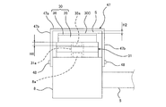
- FIG. 7 is a side view of the main part showing the leaf spring 30 and the spring seat 31 of the axle box 8 in the cart 1 shown in FIG.
- FIG. 8 is a main part rear view for explaining the attachment of the cover 47 to the axle box 8 shown in FIG.
- a spring seat 31 is placed on the upper end portion of the axle box 8.
- a hole 31a is formed at the center of the spring seat 31, and a convex portion 8a provided on the axle box 8 is fitted into the hole 31a.
- the spring seat 31 is formed by laminating a rubber plate 41, a metal plate 42, and a rubber plate 43 in order from the bottom. Both front and rear end portions 30c of the leaf spring 30 are placed on the spring seat 31 from above and are in free contact.
- the front and rear end portions 30 c of the leaf spring 30 are in contact with the upper surface of the spring seat 31 in a state where it is not fixed in the vertical direction with respect to the spring seat 31.
- the contact portion between the contact surface 33a (upper surface) of the spring seat 31 and the lower surface of the leaf spring 30 is provided with an uneven fitting structure that is a fitting portion that fits in the vertical direction with play.
- a convex portion 35a that integrally protrudes downward from the lower layer portion 35 is formed at both longitudinal end portions 30c of the leaf spring 30, and the convex portion 35a fits into the hole portion 31a of the spring seat 31 with play.
- the axle box 8 is provided with a cover 47 having a reverse U-shaped cross section that covers the upper part of the longitudinal end 30c of the leaf spring 30 with a gap S therebetween (FIGS. 1 to 3 and 7). (Not shown).
- the cover 47 has an upper wall portion 47a and side wall portions 47b that hang downward from both lateral end portions of the upper wall portion 47a.
- the lower end portion of the side wall portion 47b is attached to the axle box 8 by a fixing tool 48 such as a screw. It is fixed.
- the clearance S between the upper wall portion 47a of the cover 47 and the leaf spring 30 includes an uneven fitting structure between the leaf spring 30 and the spring seat 31 and an uneven fitting structure between the spring seat 31 and the axle box 8. Is set so that the fitted state is maintained.
- the height H2 of the gap S is set to be smaller than the height H1 of the convex portions 8a and 35a.
- the support member 29 is positioned so as to sandwich the leaf spring 30 with the end portion 4a of the lateral beam 4 in the vertical direction and supports the end portion 4a of the lateral beam 4, the required support function is provided in the first preliminary function. It can be secured by the support member 29. Therefore, even if the leaf spring 30 of the carriage 1 is damaged, the lateral beam 4 can be properly supported, and the reliability of the carriage 1 can be improved.
- the first preliminary support member 29 has a gap with respect to the leaf spring 30 when the end portion 4a of the lateral beam 4 is displaced in the vertical direction within the normal elastic deformation range of the leaf spring 30.
- the end 4a of the side beam 4 is not supported. Therefore, the design of the spring constant of the plate spring 30 is facilitated, and the load from the plate spring 30 is not applied to the first preliminary support member 29 when the plate spring is in a normal elastic deformation state, so that the first preliminary support member 29 fatigue can be prevented.
- the first preliminary support member 29 is provided on both the front side and the rear side when viewed from the center in the front-rear direction of the spring 30, damage occurs in any part in the length direction of the leaf spring 30.
- the preliminary support member 29 can support the end portion 4 a of the lateral beam 4 via the leaf spring 30.
- the axle box 8 is provided with a cover 47 that covers the upper surface of the front and rear direction end portions 30c of the plate spring 30 with a gap S between the upper surface of the front and rear direction end portions 30c of the plate spring 30. Since the fitting state of the concave-convex fitting structure between the spring 30 and the spring seat 31 is set, even if the leaf spring 30 is damaged, the leaf spring 30 can be prevented from falling off. it can.
- FIG. 9 is a drawing corresponding to FIG. 5 of the carriage 101 according to the second embodiment of the present invention.
- the preliminary support member 129 of the present embodiment is a plate-like member that is disposed below the leaf spring 30 at a position that overlaps the end 4 a of the lateral beam 4 in plan view.
- the preliminary support member 129 is curved along the lower surface of the leaf spring 30 with a gap from the leaf spring 30.
- the length in the front-rear direction of the preliminary support member 129 is shorter than the length in the front-rear direction of the contact member 33 of the end 4 a of the side beam 4.
- the preliminary support member 129 is separated from the leaf spring 30. It is spaced apart and does not support the end 4 a of the side beam 4.
- the leaf spring 30 is damaged by any chance, and the lateral end 4a of the lateral beam 4 has a predetermined elastic deformation range of the leaf spring 30.
- the preliminary support member 129 is positioned so as to sandwich the leaf spring 30 with the end portion 4a of the side beam 4 in the vertical direction when it is displaced downward, the end portion 4a of the side beam 4 is supported.
- the required support function can be secured by the preliminary support member 129. Since other configurations are the same as those of the first embodiment described above, description thereof is omitted.
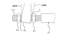
- FIG. 10 is a side view of a carriage 201 according to the third embodiment of the present invention.
- FIG. 11 is an enlarged view of a main part of the carriage 201 shown in FIG.
- a substantially U-shaped receiving frame 212 is vertically suspended from the axle box 8 when viewed from the front-rear direction.
- a rod 211 is bridged between the front and rear receiving frames 212.
- the rod 211 has a rod main body portion 211a and both end portions 211b in the front-rear direction of the rod main body portion 211a, and screws are formed on the outer peripheral surfaces of the both end portions 211b.
- Stoppers 213 and 214 which are nuts, are screwed onto the end portion 211 b of the rod 211 inserted into the inner space of the receiving frame 212 on both sides in the front-rear direction of the receiving frame 212.
- the stoppers 213 and 214 are sized so as not to pass through the internal space of the receiving frame 212, and are arranged with a predetermined gap in the front-rear direction with respect to the receiving frame 212. In this way, the rod 211, the receiving frame 212, and the stoppers 213 and 214 constitute the preliminary support mechanism 210.
- FIG. 12 is a side view of a carriage 301 according to the fourth embodiment of the present invention.
- a pair of front and rear brackets 311 are suspended from the side beam 4 integrally.
- a base end portion of a rod 312 extending toward the axle box 8 side is connected to the lower end portion of the bracket 311 via a support shaft 313 so as to be swingable up and down.
- the rod 312 has a screw formed on the outer peripheral surface of the tip portion 312b on the axle box 8 side.
- a substantially U-shaped receiving frame 314 is vertically provided on the axle box 8 when viewed from the front-rear direction, and a distal end portion 312 b of the rod 312 is inserted into the inner space of the receiving frame 314.
- Stoppers 315 and 316 that are nuts are screwed to the front end portion 312 b of the rod 312 on both sides in the front-rear direction of the receiving frame 314.
- the stoppers 315 and 316 are sized so as not to pass through the internal space of the receiving frame 314, and are disposed with a predetermined gap in the front-rear direction with respect to the receiving frame 314. In this manner, the bracket 311, the rod 312, the support shaft 313, the receiving frame 314, and the stoppers 315 and 316 constitute the preliminary support mechanism 310.
- the stoppers 315 and 316 can support the end portion 4a of the lateral beam 4 via the coupling mechanism 16 by preventing the axle box 8 from rotating. Since other configurations are the same as those of the first embodiment described above, description thereof is omitted.
- FIG. 13 is a partial cross-sectional side view of a cart 401 according to a fifth embodiment of the present invention.
- the coupling mechanism 416 of the carriage 401 includes a shaft beam 417 that integrally extends from the axle box 8 along the front-rear direction.
- a cylindrical portion 418 having an inner peripheral surface that is cylindrical and that opens on both lateral sides is provided.
- a mandrel 420 is inserted into the internal space of the cylindrical portion 418 via a rubber bush 419.
- the shaft beam 417 integrally has an overhang portion 440 that protrudes from the tubular portion 418 toward the opposite side of the axle box 8.
- a substantially U-shaped stopper 441 as viewed from the front-rear direction is provided integrally with the lateral beam 4 below the overhang portion 440.
- the stopper 441 is disposed with a predetermined gap with respect to the overhang portion 440. In this way, the overhang portion 440 and the stopper 441 constitute the preliminary support mechanism 410.
- FIG. 14 is a side view of a carriage 501 according to the sixth embodiment of the present invention.
- a hoop 513 as a stopper is bridged between the front axle box 8 and the rear axle box 8 so as to extend in the front-rear direction below the end portion 4 a of the side beam 4.
- a pair of left and right brackets 511 are vertically suspended on the axle box 8, and a pin 512 is bridged between the brackets 511 with the axial direction thereof directed in the vehicle width direction.
- a hoop 513 which is an endless belt-like body, is bridged in a slightly slack state.
- the hoop 513 is made of, for example, a fiber reinforced resin.
- the hoop 513 is slightly loosened, so that the load from the lateral beam 4 is not substantially borne. In this manner, the bracket 511, the pin 512, and the hoop 513 constitute the preliminary support mechanism 510.
- FIG. 15 is a side view of a carriage 601 according to the seventh embodiment of the present invention.
- a hoop 613 as a second preliminary support member is bridged between the front axle box 8 and the rear axle box 8 so as to extend in the front-rear direction below the end portion 4 a of the side beam 4.
- a bracket 611 is vertically suspended from the axle box 8 and a pulley 612 is rotatably provided on the bracket 611.
- a hoop 613 is stretched between the front and rear pulleys 612 with a little extra length.
- the hoop 613 is made of, for example, a fiber reinforced resin.
- a supported portion 614 that is integrally suspended from the lateral beam 4 is disposed immediately above the central portion of the hoop 613 in the front-rear direction.
- the leaf spring 30 When the leaf spring 30 is in a normal elastic deformation state, a gap is formed between the supported portion 614 and the hoop 613, or the non-supporting portion 614 is in light contact. Since the hoop 613 is stretched over the pulley 612 with a surplus length, the hoop 613 does not substantially support the supported portion 614 even if the supported portion 614 makes slight contact with the hoop 613. In this way, the bracket 611, the pulley 612, the hoop 613, and the supported portion 614 constitute the preliminary support mechanism 610.
- the supported portion 614 descending together with the lateral beam 4 is the center in the front-rear direction of the hoop 613.
- the supported portion 614 is supported by the tension of the hoop 613. Therefore, the hoop 613 can support the end portion 4a of the lateral beam 4 even if the leaf spring 30 is damaged.
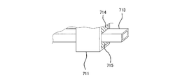
- FIG. 16 is a side view of a carriage 701 according to the eighth embodiment of the present invention.
- FIG. 17 is a perspective view of main parts of the carriage 701 shown in FIG.
- a bar 713 as a stopper is bridged between the front axle box 8 and the rear axle box 8 so as to extend in the front-rear direction below the end portion 4 a of the side beam 4.
- a cylindrical insertion frame 711 is suspended downward from the axle box 8, and a square pipe-shaped bar 713 extending in the front-rear direction is inserted into the insertion frame 711.
- elastic members 714 and 715 for example, rubber
- the axle box 8 can rotate around the axle in a range where the bar 713 does not interfere with the insertion frame 711.
- the insertion frame 711, the elastic members 714, 715, and the bar 713 constitute the preliminary support mechanism 710.
- the bar 713 is provided with peripheral device mounting portions 713a, 713b, 713c.
- peripheral device mounting portions 713a, 713b, 713c For example, at least one of a current collector 716, a trip cock 717, and a baffle 718 (snow remover) is attached to the bar 713.
- a current collector 716, a trip cock 717, and a baffle 718 is attached to the bar 713.
- a baffle 718 now remover
- the bar 713 is provided with peripheral device mounting portions 713a, 713b, 713c.
- the mounting portions 713a, 713b, and 713c may be bolt holes.
- the current collector 716 is used as a third rail-type current collector, and is disposed at the center in the front-rear direction of the carriage 701 to prevent the current collector from becoming long.
- the trip cock 717 is a part of the security device, and is disposed on the left side in front of the traveling direction of the carriage 701. When a stop signal is issued from the outside to the vehicle, the train stopper on the side of the track in the vehicle traveling direction rises, but in the unlikely event that the vehicle has advanced beyond the stop position, the trip cock on the vehicle side 717 hits the ground-side train stopper and the emergency brake is applied.
- the baffle 718 (snowblower) is for removing obstacles or accumulated snow from the front, and is attached to the tip of the bar 713.
- the bogie for the railway vehicle according to the present invention has an excellent effect of being able to appropriately support the horizontal beam even if the leaf spring of the bogie is damaged, and to improve the reliability of the bogie. It is beneficial to apply it widely to railway vehicles that can demonstrate the significance of this effect.
Landscapes
- Engineering & Computer Science (AREA)
- Mechanical Engineering (AREA)
- Vibration Prevention Devices (AREA)
- Springs (AREA)
- Vehicle Body Suspensions (AREA)
Priority Applications (7)
| Application Number | Priority Date | Filing Date | Title |
|---|---|---|---|
| EP14156449.2A EP2743153B1 (en) | 2011-07-14 | 2012-07-12 | Railcar bogie |
| EP12811394.1A EP2733040B1 (en) | 2011-07-14 | 2012-07-12 | Railcar bogie |
| US14/232,295 US9327737B2 (en) | 2011-07-14 | 2012-07-12 | Railcar bogie |
| KR1020137027171A KR101528696B1 (ko) | 2011-07-14 | 2012-07-12 | 철도 차량용 대차 |
| KR1020137027200A KR101528697B1 (ko) | 2011-07-14 | 2012-07-12 | 철도 차량용 대차 |
| CN201280033374.2A CN103635372B (zh) | 2011-07-14 | 2012-07-12 | 铁道车辆用转向架 |
| US14/154,328 US9242657B2 (en) | 2011-07-14 | 2014-01-14 | Railcar bogie |
Applications Claiming Priority (4)
| Application Number | Priority Date | Filing Date | Title |
|---|---|---|---|
| JP2011-155609 | 2011-07-14 | ||
| JP2011155609 | 2011-07-14 | ||
| JP2012076652A JP5947590B2 (ja) | 2011-07-14 | 2012-03-29 | 鉄道車両用台車 |
| JP2012-076652 | 2012-03-29 |
Related Child Applications (2)
| Application Number | Title | Priority Date | Filing Date |
|---|---|---|---|
| US14/232,295 A-371-Of-International US9327737B2 (en) | 2011-07-14 | 2012-07-12 | Railcar bogie |
| US14/154,328 Division US9242657B2 (en) | 2011-07-14 | 2014-01-14 | Railcar bogie |
Publications (1)
| Publication Number | Publication Date |
|---|---|
| WO2013008469A1 true WO2013008469A1 (ja) | 2013-01-17 |
Family
ID=47505772
Family Applications (1)
| Application Number | Title | Priority Date | Filing Date |
|---|---|---|---|
| PCT/JP2012/004514 Ceased WO2013008469A1 (ja) | 2011-07-14 | 2012-07-12 | 鉄道車両用台車 |
Country Status (7)
| Country | Link |
|---|---|
| US (2) | US9327737B2 (https=) |
| EP (2) | EP2733040B1 (https=) |
| JP (1) | JP5947590B2 (https=) |
| KR (2) | KR101528697B1 (https=) |
| CN (2) | CN103635372B (https=) |
| SG (1) | SG2014009856A (https=) |
| WO (1) | WO2013008469A1 (https=) |
Cited By (4)
| Publication number | Priority date | Publication date | Assignee | Title |
|---|---|---|---|---|
| CN105209313A (zh) * | 2013-06-19 | 2015-12-30 | 川崎重工业株式会社 | 板簧盖及具备该板簧盖的铁道车辆用转向架 |
| US10875552B2 (en) | 2015-12-25 | 2020-12-29 | Kawasaki Jukogyo Kabushiki Kaisha | Railcar bogie |
| CN116387796A (zh) * | 2023-04-04 | 2023-07-04 | 中车成型科技(青岛)有限公司 | 一种转向架天线梁结构、转向架、轨道车辆及成型工艺 |
| WO2025206009A1 (ja) * | 2024-03-29 | 2025-10-02 | 日本製鉄株式会社 | 受座 |
Families Citing this family (29)
| Publication number | Priority date | Publication date | Assignee | Title |
|---|---|---|---|---|
| JP5947590B2 (ja) | 2011-07-14 | 2016-07-06 | 川崎重工業株式会社 | 鉄道車両用台車 |
| JP5947772B2 (ja) * | 2011-07-14 | 2016-07-06 | 川崎重工業株式会社 | 鉄道車両用台車 |
| JP5779280B2 (ja) * | 2012-04-06 | 2015-09-16 | 川崎重工業株式会社 | 鉄道車両用台車 |
| US9352757B2 (en) * | 2012-04-06 | 2016-05-31 | Kawasaki Jukogyo Kabushiki Kaisha | Railcar bogie |
| USD749984S1 (en) * | 2012-05-15 | 2016-02-23 | Kawasaki Jukogyo Kabushiki Kaisha | Bogie for railcar |
| JP5765292B2 (ja) * | 2012-05-21 | 2015-08-19 | 新日鐵住金株式会社 | 鉄道車両の台車枠 |
| JP5772761B2 (ja) * | 2012-08-13 | 2015-09-02 | 新日鐵住金株式会社 | 鉄道車両の台車枠 |
| CN104822576B (zh) | 2013-01-10 | 2017-03-15 | 川崎重工业株式会社 | 铁道车辆用转向架 |
| JP6383282B2 (ja) * | 2014-12-17 | 2018-08-29 | 川崎重工業株式会社 | 鉄道車両用台車 |
| JP6506630B2 (ja) * | 2015-06-03 | 2019-04-24 | 川崎重工業株式会社 | 板バネユニット及び鉄道車両用台車 |
| JP6510938B2 (ja) * | 2015-09-10 | 2019-05-08 | 川崎重工業株式会社 | 鉄道車両用台車の電極付き板バネの製造方法 |
| JP6620007B2 (ja) | 2015-12-18 | 2019-12-11 | 川崎重工業株式会社 | 鉄道車両用操舵台車 |
| JP6944765B2 (ja) | 2016-05-16 | 2021-10-06 | 川崎重工業株式会社 | 鉄道車両台車の組立方法、測定治具及び鉄道車両台車 |
| JP6650352B2 (ja) | 2016-06-21 | 2020-02-19 | 川崎重工業株式会社 | 鉄道車両台車の組立方法及びそれに用いる軸距固定治具 |
| JP6726612B2 (ja) * | 2016-12-16 | 2020-07-22 | 川崎重工業株式会社 | 鉄道車両用台車 |
| WO2018139431A1 (ja) * | 2017-01-30 | 2018-08-02 | 川崎重工業株式会社 | 鉄道車両用台車 |
| RU173550U1 (ru) * | 2017-04-10 | 2017-08-30 | Акционерное общество "Производственное объединение "Бежицкая сталь" АО "ПО "Бежицкая сталь" | Боковая рама железнодорожной тележки |
| RU176415U1 (ru) * | 2017-05-03 | 2018-01-18 | РЕЙЛ 1520 АйПи ЛТД | Боковая рама тележки грузового вагона |
| JP6845765B2 (ja) * | 2017-08-10 | 2021-03-24 | 川崎重工業株式会社 | 鉄道車両の車上子支持装置及びそれを備えた台車ユニット |
| RU183703U1 (ru) * | 2017-10-20 | 2018-10-01 | Общество с ограниченной ответственностью Управляющая Компания "РэйлТрансХолдинг" (ООО УК "РТХ") | Боковая рама тележки грузового железнодорожного вагона |
| JP6530806B1 (ja) * | 2017-12-26 | 2019-06-12 | 川崎重工業株式会社 | 鉄道車両用台車 |
| JP7037417B2 (ja) * | 2018-03-30 | 2022-03-16 | 川崎車両株式会社 | 鉄道車両の軸箱支持装置及び弾性ブッシュ軸体 |
| JP6620183B2 (ja) * | 2018-04-16 | 2019-12-11 | 川崎重工業株式会社 | 鉄道車両用台車枠 |
| DE102018215111B3 (de) * | 2018-09-05 | 2020-01-02 | Volkswagen Aktiengesellschaft | X-Federeinrichtung für eine Kraftfahrzeug-Radaufhängung |
| CN112644548B (zh) * | 2019-10-10 | 2022-07-26 | 中车唐山机车车辆有限公司 | 一种转向架的构架 |
| CN110588897B (zh) * | 2019-11-01 | 2021-03-26 | 连云港神鹰复合材料科技有限公司 | 一种一体成型碳纤维转向架摇枕安全吊的制备方法 |
| JP7242518B2 (ja) * | 2019-12-16 | 2023-03-20 | 株式会社東芝 | 非破壊検査方法及び非破壊検査システム |
| FR3116255B1 (fr) * | 2020-11-13 | 2022-11-18 | Alstom Transp Tech | Bogie de véhicule ferroviaire, véhicule ferroviaire et procédé d’usinage associés |
| CN118877033B (zh) * | 2024-08-29 | 2025-10-31 | 中车青岛四方机车车辆股份有限公司 | 转向架的横梁组成、构架及转向架、轨道车辆 |
Citations (7)
| Publication number | Priority date | Publication date | Assignee | Title |
|---|---|---|---|---|
| JPS5058711A (https=) * | 1973-09-20 | 1975-05-21 | ||
| JPS53158007U (https=) * | 1977-05-18 | 1978-12-11 | ||
| JPS5511365U (https=) * | 1978-07-10 | 1980-01-24 | ||
| JPS61143257A (ja) * | 1984-12-17 | 1986-06-30 | 住友金属工業株式会社 | 鉄道車両用台車 |
| JPH04119266U (ja) * | 1991-04-01 | 1992-10-26 | 日本車輌製造株式会社 | 鉄道車両用台車 |
| JPH11198809A (ja) * | 1998-01-12 | 1999-07-27 | Nippon Sharyo Seizo Kaisha Ltd | 鉄道車両用台車 |
| JP2002205644A (ja) * | 2001-01-12 | 2002-07-23 | Nippon Sharyo Seizo Kaisha Ltd | 鉄道車両用台車 |
Family Cites Families (10)
| Publication number | Priority date | Publication date | Assignee | Title |
|---|---|---|---|---|
| US2098459A (en) * | 1935-06-11 | 1937-11-09 | John S Mcwhirter | Car truck |
| US3948188A (en) | 1970-06-05 | 1976-04-06 | Swiss Aluminium Ltd. | Resilient railway bogie |
| JPS5547950A (en) | 1978-09-27 | 1980-04-05 | Sumitomo Metal Ind | Truck for railway rolling stock that side beam is omitted |
| GB2091660A (en) * | 1981-01-22 | 1982-08-04 | Pullmann Standard Inc | Leaf spring railway bogies |
| JP2799078B2 (ja) | 1991-01-24 | 1998-09-17 | 川崎重工業株式会社 | 軸箱支持装置 |
| JPH07654A (ja) * | 1993-06-15 | 1995-01-06 | Brother Ind Ltd | ミシン |
| FR2782687B1 (fr) * | 1998-09-02 | 2003-01-10 | Alstom Technology | Bogie a longerons composites |
| FR2862935B1 (fr) * | 2003-12-02 | 2006-03-03 | Alstom | Dispositif de liaison souple entre un longeron et une boite d'essieu |
| CN201712620U (zh) * | 2010-05-26 | 2011-01-19 | 上海梅山钢铁股份有限公司 | 一种用于平板车连接托架自适应高度调节装置 |
| JP5947590B2 (ja) | 2011-07-14 | 2016-07-06 | 川崎重工業株式会社 | 鉄道車両用台車 |
-
2012
- 2012-03-29 JP JP2012076652A patent/JP5947590B2/ja not_active Expired - Fee Related
- 2012-07-12 US US14/232,295 patent/US9327737B2/en not_active Expired - Fee Related
- 2012-07-12 CN CN201280033374.2A patent/CN103635372B/zh not_active Expired - Fee Related
- 2012-07-12 WO PCT/JP2012/004514 patent/WO2013008469A1/ja not_active Ceased
- 2012-07-12 EP EP12811394.1A patent/EP2733040B1/en not_active Not-in-force
- 2012-07-12 KR KR1020137027200A patent/KR101528697B1/ko not_active Expired - Fee Related
- 2012-07-12 KR KR1020137027171A patent/KR101528696B1/ko not_active Expired - Fee Related
- 2012-07-12 CN CN201410041535.3A patent/CN103723158B/zh not_active Expired - Fee Related
- 2012-07-12 EP EP14156449.2A patent/EP2743153B1/en not_active Not-in-force
- 2012-07-12 SG SG2014009856A patent/SG2014009856A/en unknown
-
2014
- 2014-01-14 US US14/154,328 patent/US9242657B2/en not_active Expired - Fee Related
Patent Citations (7)
| Publication number | Priority date | Publication date | Assignee | Title |
|---|---|---|---|---|
| JPS5058711A (https=) * | 1973-09-20 | 1975-05-21 | ||
| JPS53158007U (https=) * | 1977-05-18 | 1978-12-11 | ||
| JPS5511365U (https=) * | 1978-07-10 | 1980-01-24 | ||
| JPS61143257A (ja) * | 1984-12-17 | 1986-06-30 | 住友金属工業株式会社 | 鉄道車両用台車 |
| JPH04119266U (ja) * | 1991-04-01 | 1992-10-26 | 日本車輌製造株式会社 | 鉄道車両用台車 |
| JPH11198809A (ja) * | 1998-01-12 | 1999-07-27 | Nippon Sharyo Seizo Kaisha Ltd | 鉄道車両用台車 |
| JP2002205644A (ja) * | 2001-01-12 | 2002-07-23 | Nippon Sharyo Seizo Kaisha Ltd | 鉄道車両用台車 |
Cited By (5)
| Publication number | Priority date | Publication date | Assignee | Title |
|---|---|---|---|---|
| CN105209313A (zh) * | 2013-06-19 | 2015-12-30 | 川崎重工业株式会社 | 板簧盖及具备该板簧盖的铁道车辆用转向架 |
| CN105209313B (zh) * | 2013-06-19 | 2017-03-29 | 川崎重工业株式会社 | 板簧盖及具备该板簧盖的铁道车辆用转向架 |
| US10875552B2 (en) | 2015-12-25 | 2020-12-29 | Kawasaki Jukogyo Kabushiki Kaisha | Railcar bogie |
| CN116387796A (zh) * | 2023-04-04 | 2023-07-04 | 中车成型科技(青岛)有限公司 | 一种转向架天线梁结构、转向架、轨道车辆及成型工艺 |
| WO2025206009A1 (ja) * | 2024-03-29 | 2025-10-02 | 日本製鉄株式会社 | 受座 |
Also Published As
| Publication number | Publication date |
|---|---|
| EP2733040B1 (en) | 2019-06-19 |
| US9242657B2 (en) | 2016-01-26 |
| KR20130133049A (ko) | 2013-12-05 |
| KR101528696B1 (ko) | 2015-06-12 |
| JP5947590B2 (ja) | 2016-07-06 |
| EP2733040A1 (en) | 2014-05-21 |
| EP2743153B1 (en) | 2018-12-05 |
| CN103635372B (zh) | 2016-10-26 |
| US9327737B2 (en) | 2016-05-03 |
| CN103723158A (zh) | 2014-04-16 |
| EP2733040A4 (en) | 2015-06-03 |
| EP2743153A3 (en) | 2014-09-10 |
| KR101528697B1 (ko) | 2015-06-15 |
| CN103635372A (zh) | 2014-03-12 |
| SG2014009856A (en) | 2014-05-29 |
| CN103723158B (zh) | 2016-07-27 |
| US20140144347A1 (en) | 2014-05-29 |
| US20140123870A1 (en) | 2014-05-08 |
| EP2743153A2 (en) | 2014-06-18 |
| JP2013035536A (ja) | 2013-02-21 |
| KR20130127540A (ko) | 2013-11-22 |
Similar Documents
| Publication | Publication Date | Title |
|---|---|---|
| JP5947590B2 (ja) | 鉄道車両用台車 | |
| JP5883488B2 (ja) | 鉄道車両用台車 | |
| KR101465146B1 (ko) | 철도차량용 보기 | |
| JP4685921B2 (ja) | 鉄道車両用台車 | |
| CN112519820B (zh) | 一种轨道车辆的转向架系统及轨道车辆 | |
| CN112519821B (zh) | 一种用于轨道车辆的转向架舱及转向架系统 | |
| CN105151068B (zh) | 动力转向架及轻轨车辆 | |
| CN111994120B (zh) | 轨道车辆 | |
| CN105857332A (zh) | 一种带摇枕100%地板有轨电车转向架 | |
| JP2014088176A (ja) | 鉄道車両用台車 | |
| JP2013035536A5 (https=) | ||
| CN104822576B (zh) | 铁道车辆用转向架 | |
| CN103052554A (zh) | 铁道车辆用转向架 | |
| JP5947772B2 (ja) | 鉄道車両用台車 | |
| CZ197898A3 (cs) | Závěsový systém ložiskové skříně otočného podvozku | |
| US20140346763A1 (en) | Low floor vehicles for transporting passengers | |
| WO2018139431A1 (ja) | 鉄道車両用台車 | |
| CN111994115B (zh) | 转向架 | |
| WO2017104464A1 (ja) | 鉄道車両用操舵台車 | |
| CN111232009B (zh) | 一种侧梁、构架和转向架 | |
| CN108909757A (zh) | 一种铁路车辆转向架构架及转向架 | |
| JP2002029420A (ja) | 動吸振器の取付方法及び鉄道車両 | |
| RU61667U1 (ru) | Рама двухосной рельсовой тележки |
Legal Events
| Date | Code | Title | Description |
|---|---|---|---|
| 121 | Ep: the epo has been informed by wipo that ep was designated in this application |
Ref document number: 12811394 Country of ref document: EP Kind code of ref document: A1 |
|
| ENP | Entry into the national phase |
Ref document number: 20137027171 Country of ref document: KR Kind code of ref document: A |
|
| WWE | Wipo information: entry into national phase |
Ref document number: 14232295 Country of ref document: US |
|
| NENP | Non-entry into the national phase |
Ref country code: DE |
|
| WWE | Wipo information: entry into national phase |
Ref document number: 2012811394 Country of ref document: EP |