EP2733040B1 - Railcar bogie - Google Patents
Railcar bogie Download PDFInfo
- Publication number
- EP2733040B1 EP2733040B1 EP12811394.1A EP12811394A EP2733040B1 EP 2733040 B1 EP2733040 B1 EP 2733040B1 EP 12811394 A EP12811394 A EP 12811394A EP 2733040 B1 EP2733040 B1 EP 2733040B1
- Authority
- EP
- European Patent Office
- Prior art keywords
- railcar
- cross beam
- plate spring
- end portion
- auxiliary supporting
- Prior art date
- Legal status (The legal status is an assumption and is not a legal conclusion. Google has not performed a legal analysis and makes no representation as to the accuracy of the status listed.)
- Not-in-force
Links
Images


Classifications
-
- B—PERFORMING OPERATIONS; TRANSPORTING
- B61—RAILWAYS
- B61F—RAIL VEHICLE SUSPENSIONS, e.g. UNDERFRAMES, BOGIES OR ARRANGEMENTS OF WHEEL AXLES; RAIL VEHICLES FOR USE ON TRACKS OF DIFFERENT WIDTH; PREVENTING DERAILING OF RAIL VEHICLES; WHEEL GUARDS, OBSTRUCTION REMOVERS OR THE LIKE FOR RAIL VEHICLES
- B61F5/00—Constructional details of bogies; Connections between bogies and vehicle underframes; Arrangements or devices for adjusting or allowing self-adjustment of wheel axles or bogies when rounding curves
- B61F5/26—Mounting or securing axle-boxes in vehicle or bogie underframes
- B61F5/30—Axle-boxes mounted for movement under spring control in vehicle or bogie underframes
-
- B—PERFORMING OPERATIONS; TRANSPORTING
- B61—RAILWAYS
- B61F—RAIL VEHICLE SUSPENSIONS, e.g. UNDERFRAMES, BOGIES OR ARRANGEMENTS OF WHEEL AXLES; RAIL VEHICLES FOR USE ON TRACKS OF DIFFERENT WIDTH; PREVENTING DERAILING OF RAIL VEHICLES; WHEEL GUARDS, OBSTRUCTION REMOVERS OR THE LIKE FOR RAIL VEHICLES
- B61F5/00—Constructional details of bogies; Connections between bogies and vehicle underframes; Arrangements or devices for adjusting or allowing self-adjustment of wheel axles or bogies when rounding curves
- B61F5/26—Mounting or securing axle-boxes in vehicle or bogie underframes
- B61F5/30—Axle-boxes mounted for movement under spring control in vehicle or bogie underframes
- B61F5/301—Axle-boxes mounted for movement under spring control in vehicle or bogie underframes incorporating metal springs
- B61F5/302—Leaf springs
-
- B—PERFORMING OPERATIONS; TRANSPORTING
- B61—RAILWAYS
- B61F—RAIL VEHICLE SUSPENSIONS, e.g. UNDERFRAMES, BOGIES OR ARRANGEMENTS OF WHEEL AXLES; RAIL VEHICLES FOR USE ON TRACKS OF DIFFERENT WIDTH; PREVENTING DERAILING OF RAIL VEHICLES; WHEEL GUARDS, OBSTRUCTION REMOVERS OR THE LIKE FOR RAIL VEHICLES
- B61F5/00—Constructional details of bogies; Connections between bogies and vehicle underframes; Arrangements or devices for adjusting or allowing self-adjustment of wheel axles or bogies when rounding curves
- B61F5/50—Other details
- B61F5/52—Bogie frames
Definitions
- the present invention relates to a railcar bogie from which side sills are omitted.
- a bogie for supporting a carbody of a railcar and allowing the railcar to run along a rail is provided under a floor of the carbody.
- axle boxes each configured to store a bearing for supporting an axle are supported by an axlebox suspension so as to be displaceable relative to a bogie frame in an upper-lower direction.
- the axlebox suspension and the bogie frame includes a cross beam extending in a crosswise direction and a pair of left and right side sills respectively extending from both end portions of the cross beam in a front-rear direction.
- the axlebox suspension includes axle springs constituted by coil springs each provided between the axle box and the side sill located above the axle box.
- PTL 2 proposes the bogie in which the side sills are omitted from the bogie frame.
- PTL 3 discloses a railcar bogie which forms the basis for the preamble of claim 1.
- Said railcar bogie comprises a plurality of pairs of wheels, a plurality of axles respectively interconnecting the wheels, a cross-beam extending substantially parallel to the axles, a plurality of rocker arms, and a plurality of ball joint-type means connecting the rocker arms to the cross-beam and to the plurality of axles, respectively, whereby the axles may carry out pendulum movements in substantially vertical and horizontal directions relative to the rails, and spring means interposed between the cross-beam and the rocker arms permitting movement of the latter in the mentioned directions.
- PTL4 discloses a further exemplary railcar bogie.
- the bogie frame constituted by the cross beam and the side sills is manufactured by, for example, welding heavy steel members to one another. Therefore, problems are that the weight of the bogie frame becomes heavy, and the cost for the steel members and the assembly cost become high.
- the cross beam of the bogie frame and each axle box are connected to each other by a suspension member so as to be spaced apart from each other by a certain distance.
- front-rear direction middle portions of plate springs are respectively held by and fixed to both crosswise direction end portions of the cross beam, and both front-rear direction end portions of each plate spring are respectively inserted in spring receiving portions respectively provided at lower portions of the axle boxes.
- an object of the present invention is to improve the reliability of a plate spring bogie by appropriately supporting a cross beam even if the plate spring is, for example, damaged.
- a railcar bogie includes: a cross beam configured to support a carbody of a railcar, a pair of front and rear axles arranged at both sides of the cross beam in a railcar longitudinal direction so as to extend in a railcar width direction; bearings respectively provided at both railcar width direction sides of each of the axles and configured to rotatably support the axles: axle boxes configured to respectively accommodate the bearings; plate springs extending in the railcar longitudinal direction so as to respectively support both railcar width direction end portions of the cross beam and each including (i) two railcar longitudinal direction end portions respectively supported by the axle boxes as well as (ii) a railcar longitudinal direction middle portion arranged under the cross beam.
- the railcar bogie further comprises contact members respectively provided at both railcar width direction end portions of the cross beam and respectively disposed on the railcar longitudinal direction middle portions of the plate springs from above so as to freely contact the railcar longitudinal direction middle portions of the plate springs without fixing them in an upper-lower direction; and an auxiliary supporting mechanism configured to, in a case where at least one of both railcar width direction end portions of the cross beam is displaced downward beyond a predetermined elastic deformation range of the plate spring, receive and support said one end portion of the cross beam from below.
- the auxiliary supporting mechanism supports the end portion of the cross beam, so that the required supporting function can be ensured by the auxiliary supporting mechanism. Therefore, even if the plate spring is, for example, damaged, the cross beam can be appropriately supported. Thus, the reliability of the plate spring bogie can be improved.
- the cross beam can be appropriately supported.
- the reliability of the plate spring bogie can be improved.
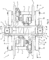
- Fig. 1 is a perspective view showing a railcar bogie 1 according to Embodiment 1 of the present invention.
- Fig. 2 is a plan view of the bogie 1 shown in Fig. 1 .
- Fig. 3 is a side view of the bogie 1 shown in Fig. 1 .
- Fig. 4 is a perspective view showing receiving seats 21 and 21 of a coupling mechanism 16 shown in Fig. 1 and their vicinities.
- the railcar bogie 1 includes a cross beam 4 extending in a railcar width direction (hereinafter also referred to as a "crosswise direction") as a bogie frame 3 configured to support a carbody 11 via air springs 2 serving as secondary suspensions.
- the railcar bogie 1 does not include side sills respectively extending from both crosswise direction end portions of the cross beam 4 in a railcar longitudinal direction (hereinafter also referred to as a "front-rear direction").
- a pair of front and rear axles 5 are respectively arranged in front of and behind the cross beam 4 so as to extend in the crosswise direction.
- Wheels 6 are respectively fixed to both crosswise direction sides of each axle 5.
- Bearings 7 configured to rotatably support the axle 5 are respectively provided at both crosswise direction end portions of the axle 5 so as to be respectively located outside the wheels 6 in the crosswise direction.
- the bearings 7 are respectively accommodated in axle boxes 8.
- An electric motor 9 is attached to the cross beam 4, and a gear box 10 that accommodates a reduction gear configured to transmit power to the axles 5 is connected to an output shaft of the electric motor 9.
- a braking device (not shown) configured to brake the rotations of the wheels 6 is also provided at the cross beam 4.
- the cross beam 4 includes: a pair of square pipes 12 extending in the crosswise direction and made of metal; and connecting plates 13 and 14 connecting the square pipes 12 and made of metal.
- the connecting plates 13 and 14 are fixed to the square pipes 12 by bolts, or the like.
- a pair of tubular connecting plates 14 are provided at each of crosswise direction end portions 4a of the cross beam 4 so as to be spaced apart from each other.
- Each of air spring bases 15 is disposed on upper surfaces of the pair of connecting plates 14.
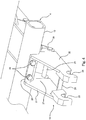
- Each of the crosswise direction end portions 4a of the cross beam 4 is coupled to the axle boxes 8 by coupling mechanisms 16.
- Each of the coupling mechanisms 16 includes an axle beam 17 extending in the front-rear direction integrally from the axle box 8.
- a tubular portion 18 that has a cylindrical inner peripheral surface and opens at both crosswise direction sides thereof is provided at an end portion of each axle beam 17.
- a core rod 20 is inserted through an internal space of each tubular portion 18 via a rubber bushing (not shown).
- a pair of receiving seats 21 and 22 constituting the coupling mechanism 16 are provided at the crosswise direction end portion 4a of the cross beam 4 so as to project in the front-rear direction.
- Upper end portions of the pair of receiving seats 21 and 22 are coupled to each other by an upper coupling plate 23, and the upper coupling plate 23 is fixed to the square pipe 12 by bolts 24.
- projecting tip ends of lower end portions of the receiving seats 21 and 22 are coupled to each other by a lower coupling plate 28.
- a fitting groove 25 that opens downward is formed at each of the receiving seats 21 and 22. Both crosswise direction end portions of the core rod 20 are respectively fitted into the fitting grooves 25 of the receiving seats 21 and 22 from below.
- a lid member 26 is fixed to the receiving seats 21 and 22 by bolts (not shown) from below so as to close lower openings of the fitting grooves 25 of the receiving seats 21 and 22.
- the core rod 20 is supported by the lid member 26 from below.
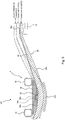
- Each of plate springs 30 extending in the front-rear direction is provided between the cross beam 4 and the axle box 8.
- Front-rear direction middle portions 30a of the plate springs 30 respectively support the crosswise direction end portions 4a of the cross beam 4, and front-rear direction end portions 30c of the plate springs 30 are respectively supported by the axle boxes 8.
- each of the plate springs 30 serves as both a primary suspension and a conventional side sill.
- Spring seats 31 are respectively attached to upper end portions of the axle boxes 8, and the front-rear direction end portions 30c of the plate springs 30 are respectively supported by the spring seats 31 from below.
- the front-rear direction middle portions 30a of the plate springs 30 are arranged under the cross beam 4, and contact members 33 (see Fig. 5 ) respectively provided at the crosswise direction end portions 4a of the cross beam 4 are respectively disposed on the front-rear direction middle portions 30a of the plate springs 30 from above.
- each of extending portions 30b each extending between the front-rear direction middle portion 30a and the front-rear direction end portion 30c is inclined downward toward the front-rear direction middle portion 30a in a side view.
- the front-rear direction middle portion 30a of the plate spring 30 is located at a position lower than the front-rear direction end portion 30c of the plate spring 30.
- a part of each of the extending portions 30b of the plate spring 30 is arranged so as to overlap the coupling mechanism 16 in a side view while being spaced apart from the coupling mechanism 16.
- a part of the extending portion 30b of the plate spring 30 extends through a space 27 sandwiched between the pair of receiving seats 21 and 22 and also extends under the upper coupling plate 23 and above the lower coupling plate 28.
- the front-rear direction middle portion 30a of the plate spring 30 is located in a space under the cross beam 4 and above first auxiliary supporting members 29 described below.
- Fig. 5 is a main portion cross-sectional view taken along line V-V of Fig. 2 and showing the cross beam 4, the plate spring 30, and the first auxiliary supporting members 29.
- Fig. 6 is a cross-sectional view taken along line VI-VI of Fig. 2 .
- a fixing plate 32 fixed to lower surfaces of the pair of square pipes 12 and made of metal (such as a general steel material) and the contact member 33 fixed to a lower surface of the fixing plate 32 and constituted by a rigid body (such as metal or fiber-reinforced resin) are provided at each of the crosswise direction end portions 4a of the cross beam 4.
- the contact member 33 does not support a lower surface of the plate spring 30.
- the contact member 33 is disposed on the front-rear direction middle portion 30a of the plate spring 30 from above so as to freely contact the front-rear direction middle portion 30a. In other words, the contact member 33 contacts an upper surface of the plate spring 30 so as not to fix the plate spring 30 in the upper-lower direction.
- Each of the front-rear direction end portions 30c of the plate spring 30 is located at a position higher than a contact surface 33a that is a lower surface of the contact member 33 of the cross beam 4.
- the contact surface 33a contacting the plate spring 30 has a substantially circular-arc shape that is convex downward in a side view. In a state where the bogie 1 is not supporting the carbody 11, the curvature of the contact surface 33a of the contact member 33 is larger than that of a portion of the plate spring 30 in a side view, the portion contacting the contact member 33.
- the plate spring 30 elastically deforms by the downward load from the carbody 11 such that the cross beam 4 moves downward, and the curvature of the portion, contacting the contact member 33, of the plate spring 30 increases.
- the curvature of the contact surface 33a of the contact member 33 is kept larger than that of the portion, contacting the contact member 33, of the plate spring 30 (solid line in Fig. 5 ).
- the curvature of the portion, contacting the contact member 33, of the plate spring 30 increases (broken line in Fig. 5 ).
- the plate spring 30 has a double-layer structure and includes a lower layer portion 35 made of fiber-reinforced resin (such as CFRP or GFRP) and an upper layer portion 36 that is thinner than the lower layer portion 35 and made of metal (such as a general steel material).
- the plate spring 30 is formed such that an upper surface of a plate spring main body portion (lower layer portion 35) made of fiber-reinforced resin is integrally covered with metal (upper layer portion 36).
- the extending portion 30b of the plate spring 30 is formed such that a thickness T thereof gradually increases in a direction from a front-rear direction end portion toward a middle portion.
- a concave-convex fitting structure including fitting portions that are fitted to each other in the upper-lower direction with a play is provided at a portion where the contact surface 33a of the contact member 33 and the upper surface of the plate spring 30 contact each other.
- a concave portion 33b that is concave upward is formed at a middle portion of the contact surface 33a of the contact member 33
- a convex portion 36a that is fitted to the concave portion 33b with a play is formed on an upper surface of the upper layer portion 36 of the plate spring 30.
- a pair of guide side walls 39 respectively projecting downward from both crosswise direction sides of the contact member 33 are provided at the cross beam 4 so as to be spaced apart from each other, and the plate spring 30 is arranged between the guide side walls 39 so as to be spaced apart from the guide side walls 39.
- the pair of guide side walls 39 are coupled to each other by the first auxiliary supporting members 29 that are respectively located at a front side and a rear side when viewed from a front-rear direction center of the plate spring 30, each extends in the crosswise direction, and each has a columnar shape.
- the first auxiliary supporting members 29 are symmetrically arranged at the front side and the rear side and constitute an auxiliary supporting mechanism 50 configured to, if the plate spring 30 is damaged, such as if the plate spring 30 breaks, support the end portion 4a of the cross beam 4 by sandwiching the plate spring 30 between the auxiliary supporting mechanism 50 and the contact member 33 of the end portion 4a of the cross beam 4.
- the first auxiliary supporting members 29 are arranged under the plate spring 30 so as to overlap the end portion 4a of the cross beam 4 in a plan view.
- a distance L1 between the pair of first auxiliary supporting members 29 at the front side and the rear side is shorter than a front-rear direction length L2 of the contact member 33 of the end portion 4a of the cross beam 4.
- the first auxiliary supporting members 29 are arranged at such positions as to be separated from the plate spring 30 , that is, as not to contact the plate spring 30 while the cross beam 4 is displaced relative to the axle box 8 in the upper-lower direction since the plate spring 30 elastically deforms between a deformation state (solid line in Fig. 5 ) when the vehicle occupancy of the carbody 11 is 0%, that is, the carbody 11 is empty and a deformation state (broken line in Fig. 5 ) when the vehicle occupancy of the carbody 11 is 100%, that is, the carbody 11 is full.
- a deformation state solid line in Fig. 5
- a deformation state broken line in Fig. 5
- the front-rear direction middle portion 30a of the plate spring 30 does not extend along the lower surface of the contact member 33 due to the damage, such as break, of the vicinity of the front-rear direction center of the plate spring 30, the front-rear direction middle portion 30a (a portion of the plate spring 30, the portion overlapping the cross beam 4 in a plan view) of the plate spring 30 inclines beyond the normal elastic deformation range and is positioned so as to be sandwiched between the auxiliary supporting member 29 and a front-rear direction end edge of the contact member 33 in the upper-lower direction by the downward load applied from the cross beam 4 (dashed line in Fig. 5 ).
- the contact member 33 of the railcar width direction end portion of the cross beam 4 supports the upper surface of the plate spring 30, and the first auxiliary supporting members 29 support the lower surface of the plate spring 30.
- the first auxiliary supporting members 29 support the end portion 4a of the cross beam 4 via the plate spring 30.
- the first auxiliary supporting members 29 support the end portion 4a of the cross beam 4 via a remaining longer portion of the plate spring 30.
- a portion, located at the rear side of the broken point, of the plate spring 30 inclines beyond the normal elastic deformation range and is positioned so as to be sandwiched between the first auxiliary supporting member 29 and the contact member 33 in the upper-lower direction by the downward load applied from the cross beam 4.
- the auxiliary supporting members 29 support the end portion 4a of the cross beam 4 via the portion, located at the rear side of the broken point, of the plate spring 30.
- the damaged plate spring 30 is positioned so as to be sandwiched between the front-rear direction end edge of the contact member 33 and the first auxiliary supporting member 29.
- the damaged plate spring 30 may be positioned so as to be sandwiched between the front-rear direction end edge of the square pipe 12 and the first auxiliary supporting member 29.
- the end portion 4a of the cross beam 4 is slightly displaced downward more than usual.
- the height and posture of the carbody 11 can be corrected by increasing the amount of expansion of the corresponding air spring 2.
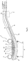
- Fig. 7 is a main portion side view showing the plate spring 30 and the spring seat 31 of the axle box 8 in the bogie 1 shown in Fig. 3 .
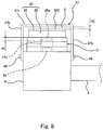
- Fig. 8 is a main portion rear view for explaining the attachment of a cover 47 to the axle box 8 shown in Fig. 7 .
- the spring seat 31 is disposed on the upper end portion of the axle box 8.
- a hole portion 31a is formed at a center of the spring seat 31, and a convex portion 8a provided on the axle box 8 is fitted in the hole portion 31a.
- the spring seat 31 is formed by stacking a rubber plate 41, a metal plate 42, and a rubber plate 43 in this order from below such that these plates 41 to 43 are adhered to one another.
- the front-rear direction end portion 30c of the plate spring 30 is disposed on the spring seat 31 from above so as to freely contact the spring seat 31.
- the front-rear direction end portion 30c of the plate spring 30 contacts an upper surface of the spring seat 31 so as not to be fixed to the spring seat 31 in the upper-lower direction.
- a concave-convex fitting structure including fitting portions that are fitted to each other in the upper-lower direction with a play is provided at a portion where the contact surface 33a (upper surface) of the spring seat 31 and the lower surface of the plate spring 30 contact each other.
- a convex portion 35a projecting downward integrally from the lower layer portion 35 is formed at the front-rear direction end portion 30c of the plate spring 30, and the convex portion 35a is fitted in the hole portion 31a of the spring seat 31 with a play.
- the cover 47 (not shown in Figs. 1 to 3 and 7 ) having an inverted U-shaped cross section is provided at the axle box 8 so as to cover an upper side of the front-rear direction end portion 30c of the plate spring 30 with a space S between the cover 47 and the front-rear direction end portion 30c.
- the cover 47 includes an upper wall portion 47a and side wall portions 47b respectively extending downward from both crosswise direction end portions of the upper wall portion 47a.
- the lower end portions of the side wall portions 47b are fixed to the axle box 8 by fixtures 48, such as screws.
- the space S between the upper wall portion 47a of the cover 47 and the plate spring 30 is set so as to maintain the fit state of the concave-convex fitting structure between the plate spring 30 and the spring seat 31 and the fit state of the concave-convex fitting structure between the spring seat 31 and the axle box 8.
- a height H2 of the space S is set to be lower than a height HI of each of the convex portions 8a and 35a.
- the auxiliary supporting members 29 position the plate spring 30 by sandwiching the plate spring 30 between each auxiliary supporting member 29 and the end portion 4a of the cross beam 4 in the upper-lower direction.
- the auxiliary supporting members 29 support the end portion 4a of the cross beam 4. Therefore, the required supporting function can be ensured by the first auxiliary supporting members 29.
- the plate spring 30 of the bogie 1 is, for example, damaged, the cross beam 4 can be appropriately supported.
- the reliability of the bogie 1 can be improved.
- the first auxiliary supporting members 29 are spaced apart from the plate spring 30, that is, do not support the end portion 4a of the cross beam 4. Therefore, the design of the spring constant of the plate spring 30 becomes easy.
- the load is not applied from the plate spring 30 to the first auxiliary supporting members 29, so that the fatigue of the first auxiliary supporting members 29 can be prevented.
- the first auxiliary supporting members 29 are respectively provided at the front side and rear side when viewed from the front-rear direction center of the spring 30. Therefore, even in a case where any length direction portion of the plate spring 30 is damaged, the auxiliary supporting members 29 can support the end portion 4a of the cross beam 4 via the plate spring 30.
- the auxiliary supporting mechanism 50 is provided separately from the coupling mechanism 16. Therefore, if the plate spring 30 is, for example, damaged, the downward load is not excessively transmitted from the cross beam 4 to the coupling mechanism 16. Thus, the excessive load is prevented from being applied to the coupling mechanism 16.
- the cover 47 is provided at the axle box 8 so as to cover the upper side of the front-rear direction end portion 30c of the plate spring 30 with the space S between the cover 47 and the upper surface of the front-rear direction end portion 30c of the plate spring 30, and the space S is set so as to maintain the fit state of the concave-convex fitting structure between the plate spring 30 and the spring seat 31. Therefore, even if the plate spring 30 is damaged, the plate spring 30 can be prevented from falling off.
- Fig. 9 is a diagram showing a bogie 101 according to Embodiment 2 of the present invention and corresponds to Fig. 5 .
- an auxiliary supporting member 129 of the present embodiment is a plate-shaped member arranged under the plate spring 30 so as to overlap the end portion 4a of the cross beam 4 in a plan view.
- the auxiliary supporting member 129 is arranged so as to be spaced apart from the plate spring 30 and curves along the lower surface of the plate spring 30.
- a front-rear direction length of the auxiliary supporting member 129 is shorter than a front-rear direction length of the contact member 33 of the end portion 4a of the cross beam 4.
- the auxiliary supporting member 129 is spaced apart from the plate spring 30, that is, does not support the end portion 4a of the cross beam 4.
- the auxiliary supporting member 129 positions the plate spring 30 by sandwiching the plate spring 30 between the auxiliary supporting member 129 and the end portion 4a of the cross beam 4 in the upper-lower direction.
- the auxiliary supporting member 129 supports the end portion 4a of the cross beam 4. Therefore, the required supporting function can be ensured by the auxiliary supporting member 129. Since the other components herein are the same as those in Embodiment 1, explanations thereof are omitted.
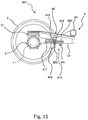
- Fig. 10 is a side view of a bogie 201 according to Embodiment 3 of the present invention.
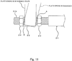
- Fig. 11 is a main portion enlarged view of the bogie 201 shown in Fig. 10 .
- a receiving frame 212 having a substantially U shape when viewed from the front-rear direction is vertically provided at each axle box 8 so as to extend downward.
- a rod 211 extends between the receiving frame 212 at the front side and the receiving frame 212 at the rear side.
- the rod 211 includes a rod main body portion 211a and front-rear direction end portions 211b respectively located at the front side and rear side of the rod main body portion 211a, and threads are formed on outer peripheral surfaces of the end portions 211b.
- Stoppers 213 and 214 that are nuts are threadedly engaged with each of the end portions 211b of the rod 211 inserted in internal spaces of the receiving frames 212, so as to be respectively located at both front-rear direction sides of the receiving frame 212.
- Each of the stoppers 213 and 214 is too big to pass through the internal space of the receiving frame 212 and is arranged so as to be separated from the receiving frame 212 by a predetermined distance in the front-rear direction.
- the rod 211, the receiving frames 212, and the stoppers 213 and 214 constitute an auxiliary supporting mechanism 210.
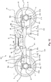
- Fig. 12 is a side view of a bogie 301 according to Embodiment 4 of the present invention.
- a pair of front and rear brackets 311 extend downward integrally from the cross beam 4.
- a base end portion of a rod 312 extending toward the axle box 8 is connected to a lower end portion of each of the brackets 311 via a support shaft 313 such that the rod 312 can swing in the upper-lower direction.
- Threads are formed on an outer peripheral surface of a tip end portion 312b of each rod 312, the tip end portion 312b being located at the axle box 8 side.
- a receiving frame 314 having a substantially U shape when viewed from the front-rear direction is vertically provided at each axle box 8.
- the tip end portion 312b of the rod 312 is inserted through an internal space of the receiving frame 314.
- Stoppers 315 and 316 that are nuts are threadedly engaged with the tip end portion 312b of each rod 312 so as to be respectively located at both front-rear direction sides of the receiving frame 314.
- Each of the stoppers 315 and 316 is too big to pass through the internal space of the receiving frame 314 and is arranged so as to be separated from the receiving frame 314 by a predetermined distance in the front-rear direction.
- the bracket 311, the rod 312, the support shaft 313, the receiving frame 314, and the stoppers 315 and 316 constitute an auxiliary supporting mechanism 310.
- Fig. 13 is a main portion side view showing a bogie 401 according to Embodiment 5 of the present invention, a part of the side view being a cross-sectional view.
- a coupling mechanism 416 of the bogie 401 includes an axle beam 417 extending in the front-rear direction integrally from the axle box 8.
- a tubular portion 418 that has a cylindrical inner peripheral surface and opens at both crosswise direction sides thereof is provided at a tip end side of the axle beam 417.
- a core rod 420 is inserted through an internal space of the tubular portion 418 via a rubber bushing 419.
- the axle beam 417 integrally includes an overhang portion 440 projecting from the tubular portion 418 toward a side opposite to the axle box 8.
- a stopper 441 having a substantially U shape when viewed from the front-rear direction is provided under the overhang portion 440 so as to be integral with the cross beam 4.
- the stopper 441 is provided so as to be spaced apart from the overhang portion 440 by a predetermined distance.
- the overhang portion 440 and the stopper 441 constitute an auxiliary supporting mechanism 410.
- Fig. 14 is a side view of a bogie 501 according to Embodiment 6 of the present invention.
- a hoop 513 that is a stopper extends between the axle box 8 at the front side and the axle box 8 at the rear side so as to be located under the end portion 4a of the cross beam 4 and extend in the front-rear direction.
- a pair of left and right brackets 511 are vertically provided at each axle box 8 so as to extend downward.
- a pin 512 extends between the brackets 511 such that an axial direction thereof corresponds to the railcar width direction.
- the hoop 513 that is an endless belt-shaped body extends between the pin 512 at the front side and the pin 512 at the rear side so as to be slightly slackened.
- the hoop 513 is made of, for example, fiber-reinforced resin.
- the plate spring 30 When the plate spring 30 is in the normal elastic deformation state, the hoop 513 is slightly slackened, so that the hoop 513 does not practically support the load applied from the cross beam 4.
- the brackets 511, the pins 512, and the hoop 513 constitute an auxiliary supporting mechanism 510.
- Fig. 15 is a side view of a bogie 601 according to Embodiment 7 of the present invention.
- a hoop 613 that is a second auxiliary supporting member extends between the axle box 8 at the front side and the axle box 8 at the rear side so as to be located under the end portion 4a of the cross beam 4 and extend in the front-rear direction.
- brackets 611 are respectively, vertically provided at the axle boxes 8 so as to extend downward
- pulleys 612 are respectively, rotatably provided at the brackets 611.
- the hoop 613 extends between the pulley 612 at the front side and the pulley 612 at the rear side so as to be slightly slackened.
- the hoop 613 is made of, for example, fiber-reinforced resin.
- a supported portion 614 extending downward integrally from the cross beam 4 is provided immediately above a front-rear direction middle portion of the hoop 613.
- the brackets 611, the pulleys 612, the hoop 613, and the supported portion 614 constitute an auxiliary supporting mechanism 610.
- the supported portion 614 that moves downward together with the cross beam 4 is received and supported from below by the front-rear direction middle portion of the hoop 613.
- the supported portion 614 is supported by the tension of the hoop 613. Therefore, even if the plate spring 30 is, for example, damaged, the hoop 613 can support the end portion 4a of the cross beam 4.
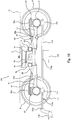
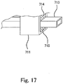
- Fig. 16 is a side view of a bogie 701 according to Embodiment 8 of the present invention.
- Fig. 17 is a main portion perspective view of the bogie 701 shown in Fig. 16 .
- a bar member 713 that is a stopper extends between the axle box 8 at the front side and the axle box 8 at the rear side so as to be located under the end portion 4a of the cross beam 4 and extend in the front-rear direction.
- tubular insertion frames 711 are respectively, vertically provided at the axle boxes 8 so as to extend downward.
- the bar member 713 extending in the front-rear direction and having a square pipe shape is inserted through the insertion frames 711.
- Elastic members 714 and 715 are inserted into each insertion frame 711 so as to sandwich the bar member 713 in the upper-lower direction. With this, when the plate spring 30 is in the normal elastic deformation state, the axle box 8 may rotate around the axle such that the bar member 713 does not contact the insertion frames 711. Thus, the insertion frames 711, the elastic members 714 and 715, and the bar member 713 constitute an auxiliary supporting mechanism 710.
- Attaching portions 713a, 713b, and 713c to which peripheral devices are attached are provided at the bar member 713.
- a current collector 716, a trip cock 717, and a rail guard 718 (snow removing unit) is attached to the bar member 713.
- the attaching portions 713a, 713b, and 713c to which the peripheral devices are attached can be formed at the bar member 713 more easily than a case where the bar member 713 is formed in, for example, a round pipe shape.
- Various fixing methods can be used as a method of attaching the peripheral device to the bar member 713.
- the attaching portions 713a, 713b, and 713c may be provided as bolt holes.
- the current collector 716 is used as a third rail type current collection device. To prevent a current collection wire from increasing in length, the current collector 716 is provided at a front-rear direction middle portion of the bogie 701.
- the trip cock 717 is a part of a protective device and is arranged at a proceeding direction front left side of the bogie 701.
- a stop signal is input to the railcar from outside
- a train stopper located beside a railway track in a railcar proceeding direction stands up.
- the trip cock 717 of the railcar hits the train stopper on the ground.
- an emergency brake is activated.
- the rail guard 718 (snow removing unit) is used to remove obstacles in front or snow on the ground and is attached to the tip end portion of the bar member 713.
- the railcar bogie according to the present invention has an excellent effect of being able to appropriately support the cross beam even if the plate spring of the bogie is, for example, damaged, and to improve the reliability of the bogie.
Landscapes
- Engineering & Computer Science (AREA)
- Mechanical Engineering (AREA)
- Vibration Prevention Devices (AREA)
- Springs (AREA)
- Vehicle Body Suspensions (AREA)
Priority Applications (1)
| Application Number | Priority Date | Filing Date | Title |
|---|---|---|---|
| EP14156449.2A EP2743153B1 (en) | 2011-07-14 | 2012-07-12 | Railcar bogie |
Applications Claiming Priority (3)
| Application Number | Priority Date | Filing Date | Title |
|---|---|---|---|
| JP2011155609 | 2011-07-14 | ||
| JP2012076652A JP5947590B2 (ja) | 2011-07-14 | 2012-03-29 | 鉄道車両用台車 |
| PCT/JP2012/004514 WO2013008469A1 (ja) | 2011-07-14 | 2012-07-12 | 鉄道車両用台車 |
Related Child Applications (2)
| Application Number | Title | Priority Date | Filing Date |
|---|---|---|---|
| EP14156449.2A Division-Into EP2743153B1 (en) | 2011-07-14 | 2012-07-12 | Railcar bogie |
| EP14156449.2A Division EP2743153B1 (en) | 2011-07-14 | 2012-07-12 | Railcar bogie |
Publications (3)
| Publication Number | Publication Date |
|---|---|
| EP2733040A1 EP2733040A1 (en) | 2014-05-21 |
| EP2733040A4 EP2733040A4 (en) | 2015-06-03 |
| EP2733040B1 true EP2733040B1 (en) | 2019-06-19 |
Family
ID=47505772
Family Applications (2)
| Application Number | Title | Priority Date | Filing Date |
|---|---|---|---|
| EP12811394.1A Not-in-force EP2733040B1 (en) | 2011-07-14 | 2012-07-12 | Railcar bogie |
| EP14156449.2A Not-in-force EP2743153B1 (en) | 2011-07-14 | 2012-07-12 | Railcar bogie |
Family Applications After (1)
| Application Number | Title | Priority Date | Filing Date |
|---|---|---|---|
| EP14156449.2A Not-in-force EP2743153B1 (en) | 2011-07-14 | 2012-07-12 | Railcar bogie |
Country Status (7)
| Country | Link |
|---|---|
| US (2) | US9327737B2 (https=) |
| EP (2) | EP2733040B1 (https=) |
| JP (1) | JP5947590B2 (https=) |
| KR (2) | KR101528697B1 (https=) |
| CN (2) | CN103635372B (https=) |
| SG (1) | SG2014009856A (https=) |
| WO (1) | WO2013008469A1 (https=) |
Families Citing this family (33)
| Publication number | Priority date | Publication date | Assignee | Title |
|---|---|---|---|---|
| JP5947590B2 (ja) | 2011-07-14 | 2016-07-06 | 川崎重工業株式会社 | 鉄道車両用台車 |
| JP5947772B2 (ja) * | 2011-07-14 | 2016-07-06 | 川崎重工業株式会社 | 鉄道車両用台車 |
| JP5779280B2 (ja) * | 2012-04-06 | 2015-09-16 | 川崎重工業株式会社 | 鉄道車両用台車 |
| US9352757B2 (en) * | 2012-04-06 | 2016-05-31 | Kawasaki Jukogyo Kabushiki Kaisha | Railcar bogie |
| USD749984S1 (en) * | 2012-05-15 | 2016-02-23 | Kawasaki Jukogyo Kabushiki Kaisha | Bogie for railcar |
| JP5765292B2 (ja) * | 2012-05-21 | 2015-08-19 | 新日鐵住金株式会社 | 鉄道車両の台車枠 |
| JP5772761B2 (ja) * | 2012-08-13 | 2015-09-02 | 新日鐵住金株式会社 | 鉄道車両の台車枠 |
| CN104822576B (zh) | 2013-01-10 | 2017-03-15 | 川崎重工业株式会社 | 铁道车辆用转向架 |
| JP6088366B2 (ja) * | 2013-06-19 | 2017-03-01 | 川崎重工業株式会社 | 板バネカバー及びそれを備えた鉄道車両用台車 |
| JP6383282B2 (ja) * | 2014-12-17 | 2018-08-29 | 川崎重工業株式会社 | 鉄道車両用台車 |
| JP6506630B2 (ja) * | 2015-06-03 | 2019-04-24 | 川崎重工業株式会社 | 板バネユニット及び鉄道車両用台車 |
| JP6510938B2 (ja) * | 2015-09-10 | 2019-05-08 | 川崎重工業株式会社 | 鉄道車両用台車の電極付き板バネの製造方法 |
| JP6620007B2 (ja) | 2015-12-18 | 2019-12-11 | 川崎重工業株式会社 | 鉄道車両用操舵台車 |
| JP6557595B2 (ja) | 2015-12-25 | 2019-08-07 | 川崎重工業株式会社 | 鉄道車両用台車 |
| JP6944765B2 (ja) | 2016-05-16 | 2021-10-06 | 川崎重工業株式会社 | 鉄道車両台車の組立方法、測定治具及び鉄道車両台車 |
| JP6650352B2 (ja) | 2016-06-21 | 2020-02-19 | 川崎重工業株式会社 | 鉄道車両台車の組立方法及びそれに用いる軸距固定治具 |
| JP6726612B2 (ja) * | 2016-12-16 | 2020-07-22 | 川崎重工業株式会社 | 鉄道車両用台車 |
| WO2018139431A1 (ja) * | 2017-01-30 | 2018-08-02 | 川崎重工業株式会社 | 鉄道車両用台車 |
| RU173550U1 (ru) * | 2017-04-10 | 2017-08-30 | Акционерное общество "Производственное объединение "Бежицкая сталь" АО "ПО "Бежицкая сталь" | Боковая рама железнодорожной тележки |
| RU176415U1 (ru) * | 2017-05-03 | 2018-01-18 | РЕЙЛ 1520 АйПи ЛТД | Боковая рама тележки грузового вагона |
| JP6845765B2 (ja) * | 2017-08-10 | 2021-03-24 | 川崎重工業株式会社 | 鉄道車両の車上子支持装置及びそれを備えた台車ユニット |
| RU183703U1 (ru) * | 2017-10-20 | 2018-10-01 | Общество с ограниченной ответственностью Управляющая Компания "РэйлТрансХолдинг" (ООО УК "РТХ") | Боковая рама тележки грузового железнодорожного вагона |
| JP6530806B1 (ja) * | 2017-12-26 | 2019-06-12 | 川崎重工業株式会社 | 鉄道車両用台車 |
| JP7037417B2 (ja) * | 2018-03-30 | 2022-03-16 | 川崎車両株式会社 | 鉄道車両の軸箱支持装置及び弾性ブッシュ軸体 |
| JP6620183B2 (ja) * | 2018-04-16 | 2019-12-11 | 川崎重工業株式会社 | 鉄道車両用台車枠 |
| DE102018215111B3 (de) * | 2018-09-05 | 2020-01-02 | Volkswagen Aktiengesellschaft | X-Federeinrichtung für eine Kraftfahrzeug-Radaufhängung |
| CN112644548B (zh) * | 2019-10-10 | 2022-07-26 | 中车唐山机车车辆有限公司 | 一种转向架的构架 |
| CN110588897B (zh) * | 2019-11-01 | 2021-03-26 | 连云港神鹰复合材料科技有限公司 | 一种一体成型碳纤维转向架摇枕安全吊的制备方法 |
| JP7242518B2 (ja) * | 2019-12-16 | 2023-03-20 | 株式会社東芝 | 非破壊検査方法及び非破壊検査システム |
| FR3116255B1 (fr) * | 2020-11-13 | 2022-11-18 | Alstom Transp Tech | Bogie de véhicule ferroviaire, véhicule ferroviaire et procédé d’usinage associés |
| CN116387796A (zh) * | 2023-04-04 | 2023-07-04 | 中车成型科技(青岛)有限公司 | 一种转向架天线梁结构、转向架、轨道车辆及成型工艺 |
| WO2025206009A1 (ja) * | 2024-03-29 | 2025-10-02 | 日本製鉄株式会社 | 受座 |
| CN118877033B (zh) * | 2024-08-29 | 2025-10-31 | 中车青岛四方机车车辆股份有限公司 | 转向架的横梁组成、构架及转向架、轨道车辆 |
Family Cites Families (17)
| Publication number | Priority date | Publication date | Assignee | Title |
|---|---|---|---|---|
| US2098459A (en) * | 1935-06-11 | 1937-11-09 | John S Mcwhirter | Car truck |
| CH563905A5 (https=) * | 1973-09-20 | 1975-07-15 | Alusuisse | |
| US3948188A (en) | 1970-06-05 | 1976-04-06 | Swiss Aluminium Ltd. | Resilient railway bogie |
| JPS5633802Y2 (https=) * | 1977-05-18 | 1981-08-10 | ||
| JPS5511365U (https=) * | 1978-07-10 | 1980-01-24 | ||
| JPS5547950A (en) | 1978-09-27 | 1980-04-05 | Sumitomo Metal Ind | Truck for railway rolling stock that side beam is omitted |
| GB2091660A (en) * | 1981-01-22 | 1982-08-04 | Pullmann Standard Inc | Leaf spring railway bogies |
| JPS61143257A (ja) * | 1984-12-17 | 1986-06-30 | 住友金属工業株式会社 | 鉄道車両用台車 |
| JP2799078B2 (ja) | 1991-01-24 | 1998-09-17 | 川崎重工業株式会社 | 軸箱支持装置 |
| JPH04119266U (ja) * | 1991-04-01 | 1992-10-26 | 日本車輌製造株式会社 | 鉄道車両用台車 |
| JPH07654A (ja) * | 1993-06-15 | 1995-01-06 | Brother Ind Ltd | ミシン |
| JPH11198809A (ja) * | 1998-01-12 | 1999-07-27 | Nippon Sharyo Seizo Kaisha Ltd | 鉄道車両用台車 |
| FR2782687B1 (fr) * | 1998-09-02 | 2003-01-10 | Alstom Technology | Bogie a longerons composites |
| JP3579767B2 (ja) * | 2001-01-12 | 2004-10-20 | 日本車輌製造株式会社 | 鉄道車両用台車 |
| FR2862935B1 (fr) * | 2003-12-02 | 2006-03-03 | Alstom | Dispositif de liaison souple entre un longeron et une boite d'essieu |
| CN201712620U (zh) * | 2010-05-26 | 2011-01-19 | 上海梅山钢铁股份有限公司 | 一种用于平板车连接托架自适应高度调节装置 |
| JP5947590B2 (ja) | 2011-07-14 | 2016-07-06 | 川崎重工業株式会社 | 鉄道車両用台車 |
-
2012
- 2012-03-29 JP JP2012076652A patent/JP5947590B2/ja not_active Expired - Fee Related
- 2012-07-12 US US14/232,295 patent/US9327737B2/en not_active Expired - Fee Related
- 2012-07-12 CN CN201280033374.2A patent/CN103635372B/zh not_active Expired - Fee Related
- 2012-07-12 WO PCT/JP2012/004514 patent/WO2013008469A1/ja not_active Ceased
- 2012-07-12 EP EP12811394.1A patent/EP2733040B1/en not_active Not-in-force
- 2012-07-12 KR KR1020137027200A patent/KR101528697B1/ko not_active Expired - Fee Related
- 2012-07-12 KR KR1020137027171A patent/KR101528696B1/ko not_active Expired - Fee Related
- 2012-07-12 CN CN201410041535.3A patent/CN103723158B/zh not_active Expired - Fee Related
- 2012-07-12 EP EP14156449.2A patent/EP2743153B1/en not_active Not-in-force
- 2012-07-12 SG SG2014009856A patent/SG2014009856A/en unknown
-
2014
- 2014-01-14 US US14/154,328 patent/US9242657B2/en not_active Expired - Fee Related
Non-Patent Citations (1)
| Title |
|---|
| None * |
Also Published As
| Publication number | Publication date |
|---|---|
| US9242657B2 (en) | 2016-01-26 |
| KR20130133049A (ko) | 2013-12-05 |
| KR101528696B1 (ko) | 2015-06-12 |
| JP5947590B2 (ja) | 2016-07-06 |
| EP2733040A1 (en) | 2014-05-21 |
| EP2743153B1 (en) | 2018-12-05 |
| CN103635372B (zh) | 2016-10-26 |
| US9327737B2 (en) | 2016-05-03 |
| CN103723158A (zh) | 2014-04-16 |
| EP2733040A4 (en) | 2015-06-03 |
| EP2743153A3 (en) | 2014-09-10 |
| KR101528697B1 (ko) | 2015-06-15 |
| CN103635372A (zh) | 2014-03-12 |
| SG2014009856A (en) | 2014-05-29 |
| CN103723158B (zh) | 2016-07-27 |
| WO2013008469A1 (ja) | 2013-01-17 |
| US20140144347A1 (en) | 2014-05-29 |
| US20140123870A1 (en) | 2014-05-08 |
| EP2743153A2 (en) | 2014-06-18 |
| JP2013035536A (ja) | 2013-02-21 |
| KR20130127540A (ko) | 2013-11-22 |
Similar Documents
| Publication | Publication Date | Title |
|---|---|---|
| EP2733040B1 (en) | Railcar bogie | |
| EP2733041B1 (en) | Railway vehicle truck | |
| US8656839B2 (en) | Railcar bogie | |
| US8371234B2 (en) | Bogie for railway vehicle | |
| EP2944534B1 (en) | Railcar bogie | |
| EP2835300B1 (en) | Railcar bogie | |
| US9802627B2 (en) | Railcar bogie | |
| EP3473515B1 (en) | Frame of bogie | |
| CN111994120B (zh) | 轨道车辆 | |
| US9421987B2 (en) | Chassis frame for rail vehicles | |
| CN108045390A (zh) | 宽轨地铁车辆轴箱内置式转向架 | |
| EP3235704B1 (en) | Bogie for railway vehicle | |
| CN110450807B (zh) | 一种单轴转向架 | |
| US9352757B2 (en) | Railcar bogie | |
| CN111994115B (zh) | 转向架 | |
| JP5947772B2 (ja) | 鉄道車両用台車 | |
| CN201544977U (zh) | 一种铁路货车轴箱弹性定位三轴转向架 | |
| EP2366599B1 (en) | Rail vehicle, in particular a low-floor rail vehicle | |
| RU2328397C2 (ru) | Рама двухосной рельсовой тележки | |
| ES2730624T3 (es) | Boje |
Legal Events
| Date | Code | Title | Description |
|---|---|---|---|
| PUAI | Public reference made under article 153(3) epc to a published international application that has entered the european phase |
Free format text: ORIGINAL CODE: 0009012 |
|
| 17P | Request for examination filed |
Effective date: 20140210 |
|
| AK | Designated contracting states |
Kind code of ref document: A1 Designated state(s): AL AT BE BG CH CY CZ DE DK EE ES FI FR GB GR HR HU IE IS IT LI LT LU LV MC MK MT NL NO PL PT RO RS SE SI SK SM TR |
|
| DAX | Request for extension of the european patent (deleted) | ||
| RA4 | Supplementary search report drawn up and despatched (corrected) |
Effective date: 20150507 |
|
| RIC1 | Information provided on ipc code assigned before grant |
Ipc: B61F 5/30 20060101ALI20150429BHEP Ipc: B61F 5/52 20060101AFI20150429BHEP |
|
| GRAP | Despatch of communication of intention to grant a patent |
Free format text: ORIGINAL CODE: EPIDOSNIGR1 |
|
| STAA | Information on the status of an ep patent application or granted ep patent |
Free format text: STATUS: GRANT OF PATENT IS INTENDED |
|
| INTG | Intention to grant announced |
Effective date: 20181220 |
|
| GRAS | Grant fee paid |
Free format text: ORIGINAL CODE: EPIDOSNIGR3 |
|
| GRAA | (expected) grant |
Free format text: ORIGINAL CODE: 0009210 |
|
| STAA | Information on the status of an ep patent application or granted ep patent |
Free format text: STATUS: THE PATENT HAS BEEN GRANTED |
|
| AK | Designated contracting states |
Kind code of ref document: B1 Designated state(s): AL AT BE BG CH CY CZ DE DK EE ES FI FR GB GR HR HU IE IS IT LI LT LU LV MC MK MT NL NO PL PT RO RS SE SI SK SM TR |
|
| REG | Reference to a national code |
Ref country code: GB Ref legal event code: FG4D |
|
| REG | Reference to a national code |
Ref country code: CH Ref legal event code: EP |
|
| REG | Reference to a national code |
Ref country code: IE Ref legal event code: FG4D |
|
| REG | Reference to a national code |
Ref country code: DE Ref legal event code: R096 Ref document number: 602012061225 Country of ref document: DE |
|
| REG | Reference to a national code |
Ref country code: AT Ref legal event code: REF Ref document number: 1145124 Country of ref document: AT Kind code of ref document: T Effective date: 20190715 |
|
| REG | Reference to a national code |
Ref country code: NL Ref legal event code: MP Effective date: 20190619 |
|
| PG25 | Lapsed in a contracting state [announced via postgrant information from national office to epo] |
Ref country code: SE Free format text: LAPSE BECAUSE OF FAILURE TO SUBMIT A TRANSLATION OF THE DESCRIPTION OR TO PAY THE FEE WITHIN THE PRESCRIBED TIME-LIMIT Effective date: 20190619 Ref country code: LT Free format text: LAPSE BECAUSE OF FAILURE TO SUBMIT A TRANSLATION OF THE DESCRIPTION OR TO PAY THE FEE WITHIN THE PRESCRIBED TIME-LIMIT Effective date: 20190619 Ref country code: AL Free format text: LAPSE BECAUSE OF FAILURE TO SUBMIT A TRANSLATION OF THE DESCRIPTION OR TO PAY THE FEE WITHIN THE PRESCRIBED TIME-LIMIT Effective date: 20190619 Ref country code: NO Free format text: LAPSE BECAUSE OF FAILURE TO SUBMIT A TRANSLATION OF THE DESCRIPTION OR TO PAY THE FEE WITHIN THE PRESCRIBED TIME-LIMIT Effective date: 20190919 Ref country code: HR Free format text: LAPSE BECAUSE OF FAILURE TO SUBMIT A TRANSLATION OF THE DESCRIPTION OR TO PAY THE FEE WITHIN THE PRESCRIBED TIME-LIMIT Effective date: 20190619 Ref country code: FI Free format text: LAPSE BECAUSE OF FAILURE TO SUBMIT A TRANSLATION OF THE DESCRIPTION OR TO PAY THE FEE WITHIN THE PRESCRIBED TIME-LIMIT Effective date: 20190619 |
|
| REG | Reference to a national code |
Ref country code: LT Ref legal event code: MG4D |
|
| PG25 | Lapsed in a contracting state [announced via postgrant information from national office to epo] |
Ref country code: BG Free format text: LAPSE BECAUSE OF FAILURE TO SUBMIT A TRANSLATION OF THE DESCRIPTION OR TO PAY THE FEE WITHIN THE PRESCRIBED TIME-LIMIT Effective date: 20190919 Ref country code: RS Free format text: LAPSE BECAUSE OF FAILURE TO SUBMIT A TRANSLATION OF THE DESCRIPTION OR TO PAY THE FEE WITHIN THE PRESCRIBED TIME-LIMIT Effective date: 20190619 Ref country code: GR Free format text: LAPSE BECAUSE OF FAILURE TO SUBMIT A TRANSLATION OF THE DESCRIPTION OR TO PAY THE FEE WITHIN THE PRESCRIBED TIME-LIMIT Effective date: 20190920 Ref country code: LV Free format text: LAPSE BECAUSE OF FAILURE TO SUBMIT A TRANSLATION OF THE DESCRIPTION OR TO PAY THE FEE WITHIN THE PRESCRIBED TIME-LIMIT Effective date: 20190619 |
|
| REG | Reference to a national code |
Ref country code: AT Ref legal event code: MK05 Ref document number: 1145124 Country of ref document: AT Kind code of ref document: T Effective date: 20190619 |
|
| PG25 | Lapsed in a contracting state [announced via postgrant information from national office to epo] |
Ref country code: EE Free format text: LAPSE BECAUSE OF FAILURE TO SUBMIT A TRANSLATION OF THE DESCRIPTION OR TO PAY THE FEE WITHIN THE PRESCRIBED TIME-LIMIT Effective date: 20190619 Ref country code: AT Free format text: LAPSE BECAUSE OF FAILURE TO SUBMIT A TRANSLATION OF THE DESCRIPTION OR TO PAY THE FEE WITHIN THE PRESCRIBED TIME-LIMIT Effective date: 20190619 Ref country code: PT Free format text: LAPSE BECAUSE OF FAILURE TO SUBMIT A TRANSLATION OF THE DESCRIPTION OR TO PAY THE FEE WITHIN THE PRESCRIBED TIME-LIMIT Effective date: 20191021 Ref country code: SK Free format text: LAPSE BECAUSE OF FAILURE TO SUBMIT A TRANSLATION OF THE DESCRIPTION OR TO PAY THE FEE WITHIN THE PRESCRIBED TIME-LIMIT Effective date: 20190619 Ref country code: NL Free format text: LAPSE BECAUSE OF FAILURE TO SUBMIT A TRANSLATION OF THE DESCRIPTION OR TO PAY THE FEE WITHIN THE PRESCRIBED TIME-LIMIT Effective date: 20190619 Ref country code: CZ Free format text: LAPSE BECAUSE OF FAILURE TO SUBMIT A TRANSLATION OF THE DESCRIPTION OR TO PAY THE FEE WITHIN THE PRESCRIBED TIME-LIMIT Effective date: 20190619 Ref country code: RO Free format text: LAPSE BECAUSE OF FAILURE TO SUBMIT A TRANSLATION OF THE DESCRIPTION OR TO PAY THE FEE WITHIN THE PRESCRIBED TIME-LIMIT Effective date: 20190619 |
|
| PG25 | Lapsed in a contracting state [announced via postgrant information from national office to epo] |
Ref country code: IS Free format text: LAPSE BECAUSE OF FAILURE TO SUBMIT A TRANSLATION OF THE DESCRIPTION OR TO PAY THE FEE WITHIN THE PRESCRIBED TIME-LIMIT Effective date: 20191019 Ref country code: ES Free format text: LAPSE BECAUSE OF FAILURE TO SUBMIT A TRANSLATION OF THE DESCRIPTION OR TO PAY THE FEE WITHIN THE PRESCRIBED TIME-LIMIT Effective date: 20190619 Ref country code: SM Free format text: LAPSE BECAUSE OF FAILURE TO SUBMIT A TRANSLATION OF THE DESCRIPTION OR TO PAY THE FEE WITHIN THE PRESCRIBED TIME-LIMIT Effective date: 20190619 Ref country code: IT Free format text: LAPSE BECAUSE OF FAILURE TO SUBMIT A TRANSLATION OF THE DESCRIPTION OR TO PAY THE FEE WITHIN THE PRESCRIBED TIME-LIMIT Effective date: 20190619 |
|
| REG | Reference to a national code |
Ref country code: CH Ref legal event code: PL |
|
| PG25 | Lapsed in a contracting state [announced via postgrant information from national office to epo] |
Ref country code: TR Free format text: LAPSE BECAUSE OF FAILURE TO SUBMIT A TRANSLATION OF THE DESCRIPTION OR TO PAY THE FEE WITHIN THE PRESCRIBED TIME-LIMIT Effective date: 20190619 Ref country code: MC Free format text: LAPSE BECAUSE OF FAILURE TO SUBMIT A TRANSLATION OF THE DESCRIPTION OR TO PAY THE FEE WITHIN THE PRESCRIBED TIME-LIMIT Effective date: 20190619 |
|
| REG | Reference to a national code |
Ref country code: BE Ref legal event code: MM Effective date: 20190731 |
|
| PG25 | Lapsed in a contracting state [announced via postgrant information from national office to epo] |
Ref country code: PL Free format text: LAPSE BECAUSE OF FAILURE TO SUBMIT A TRANSLATION OF THE DESCRIPTION OR TO PAY THE FEE WITHIN THE PRESCRIBED TIME-LIMIT Effective date: 20190619 Ref country code: DK Free format text: LAPSE BECAUSE OF FAILURE TO SUBMIT A TRANSLATION OF THE DESCRIPTION OR TO PAY THE FEE WITHIN THE PRESCRIBED TIME-LIMIT Effective date: 20190619 |
|
| PG25 | Lapsed in a contracting state [announced via postgrant information from national office to epo] |
Ref country code: CH Free format text: LAPSE BECAUSE OF NON-PAYMENT OF DUE FEES Effective date: 20190731 Ref country code: BE Free format text: LAPSE BECAUSE OF NON-PAYMENT OF DUE FEES Effective date: 20190731 Ref country code: LU Free format text: LAPSE BECAUSE OF NON-PAYMENT OF DUE FEES Effective date: 20190712 Ref country code: LI Free format text: LAPSE BECAUSE OF NON-PAYMENT OF DUE FEES Effective date: 20190731 Ref country code: IS Free format text: LAPSE BECAUSE OF FAILURE TO SUBMIT A TRANSLATION OF THE DESCRIPTION OR TO PAY THE FEE WITHIN THE PRESCRIBED TIME-LIMIT Effective date: 20200224 |
|
| REG | Reference to a national code |
Ref country code: DE Ref legal event code: R097 Ref document number: 602012061225 Country of ref document: DE |
|
| PLBE | No opposition filed within time limit |
Free format text: ORIGINAL CODE: 0009261 |
|
| STAA | Information on the status of an ep patent application or granted ep patent |
Free format text: STATUS: NO OPPOSITION FILED WITHIN TIME LIMIT |
|
| PG2D | Information on lapse in contracting state deleted |
Ref country code: IS |
|
| PG25 | Lapsed in a contracting state [announced via postgrant information from national office to epo] |
Ref country code: IE Free format text: LAPSE BECAUSE OF NON-PAYMENT OF DUE FEES Effective date: 20190712 |
|
| 26N | No opposition filed |
Effective date: 20200603 |
|
| PG25 | Lapsed in a contracting state [announced via postgrant information from national office to epo] |
Ref country code: SI Free format text: LAPSE BECAUSE OF FAILURE TO SUBMIT A TRANSLATION OF THE DESCRIPTION OR TO PAY THE FEE WITHIN THE PRESCRIBED TIME-LIMIT Effective date: 20190619 |
|
| GBPC | Gb: european patent ceased through non-payment of renewal fee |
Effective date: 20190919 |
|
| PG25 | Lapsed in a contracting state [announced via postgrant information from national office to epo] |
Ref country code: GB Free format text: LAPSE BECAUSE OF NON-PAYMENT OF DUE FEES Effective date: 20190919 |
|
| PG25 | Lapsed in a contracting state [announced via postgrant information from national office to epo] |
Ref country code: CY Free format text: LAPSE BECAUSE OF FAILURE TO SUBMIT A TRANSLATION OF THE DESCRIPTION OR TO PAY THE FEE WITHIN THE PRESCRIBED TIME-LIMIT Effective date: 20190619 |
|
| PG25 | Lapsed in a contracting state [announced via postgrant information from national office to epo] |
Ref country code: HU Free format text: LAPSE BECAUSE OF FAILURE TO SUBMIT A TRANSLATION OF THE DESCRIPTION OR TO PAY THE FEE WITHIN THE PRESCRIBED TIME-LIMIT; INVALID AB INITIO Effective date: 20120712 Ref country code: MT Free format text: LAPSE BECAUSE OF FAILURE TO SUBMIT A TRANSLATION OF THE DESCRIPTION OR TO PAY THE FEE WITHIN THE PRESCRIBED TIME-LIMIT Effective date: 20190619 |
|
| PGFP | Annual fee paid to national office [announced via postgrant information from national office to epo] |
Ref country code: FR Payment date: 20210611 Year of fee payment: 10 |
|
| PGFP | Annual fee paid to national office [announced via postgrant information from national office to epo] |
Ref country code: DE Payment date: 20210616 Year of fee payment: 10 |
|
| PG25 | Lapsed in a contracting state [announced via postgrant information from national office to epo] |
Ref country code: MK Free format text: LAPSE BECAUSE OF FAILURE TO SUBMIT A TRANSLATION OF THE DESCRIPTION OR TO PAY THE FEE WITHIN THE PRESCRIBED TIME-LIMIT Effective date: 20190619 |
|
| REG | Reference to a national code |
Ref country code: DE Ref legal event code: R119 Ref document number: 602012061225 Country of ref document: DE |
|
| PG25 | Lapsed in a contracting state [announced via postgrant information from national office to epo] |
Ref country code: FR Free format text: LAPSE BECAUSE OF NON-PAYMENT OF DUE FEES Effective date: 20220731 |
|
| PG25 | Lapsed in a contracting state [announced via postgrant information from national office to epo] |
Ref country code: DE Free format text: LAPSE BECAUSE OF NON-PAYMENT OF DUE FEES Effective date: 20230201 |