WO2013001995A1 - 係止装置 - Google Patents
係止装置 Download PDFInfo
- Publication number
- WO2013001995A1 WO2013001995A1 PCT/JP2012/064478 JP2012064478W WO2013001995A1 WO 2013001995 A1 WO2013001995 A1 WO 2013001995A1 JP 2012064478 W JP2012064478 W JP 2012064478W WO 2013001995 A1 WO2013001995 A1 WO 2013001995A1
- Authority
- WO
- WIPO (PCT)
- Prior art keywords
- shaft member
- cam
- contact surface
- introduction path
- shaft
- Prior art date
- Legal status (The legal status is an assumption and is not a legal conclusion. Google has not performed a legal analysis and makes no representation as to the accuracy of the status listed.)
- Ceased
Links
Images





Classifications
-
- B—PERFORMING OPERATIONS; TRANSPORTING
- B60—VEHICLES IN GENERAL
- B60R—VEHICLES, VEHICLE FITTINGS, OR VEHICLE PARTS, NOT OTHERWISE PROVIDED FOR
- B60R5/00—Compartments within vehicle body primarily intended or sufficiently spacious for trunks, suit-cases, or the like
- B60R5/04—Compartments within vehicle body primarily intended or sufficiently spacious for trunks, suit-cases, or the like arranged at rear of vehicle
- B60R5/044—Compartments within vehicle body primarily intended or sufficiently spacious for trunks, suit-cases, or the like arranged at rear of vehicle luggage covering means, e.g. parcel shelves
- B60R5/045—Compartments within vehicle body primarily intended or sufficiently spacious for trunks, suit-cases, or the like arranged at rear of vehicle luggage covering means, e.g. parcel shelves collapsible or transformable
- B60R5/047—Compartments within vehicle body primarily intended or sufficiently spacious for trunks, suit-cases, or the like arranged at rear of vehicle luggage covering means, e.g. parcel shelves collapsible or transformable collapsible by rolling-up
Definitions
- the present invention relates to a locking device for detachably locking a shaft member at a locking position against an urging force.
- Patent Document 1 Conventionally, as a locking device, for example, there is Patent Document 1.
- the stopper pin provided on both sides of the leading edge of the tonneau cover can be detachably locked by the stopper groove mechanism.
- the present invention provides a locking device that can improve operability.
- the first aspect of the present invention is arranged adjacent to the introduction path forming member formed with a linear shaft member introduction path for receiving a shaft member that moves against an urging force,
- a cam that is movable in a direction that intersects the shaft member introduction path, a locking groove that is formed in the cam and holds the shaft member in a locking position, and is formed in the cam;
- By sliding with the shaft member that has entered the introduction path the cam is moved, and a first contact surface that guides the shaft member to the locking groove is formed on the cam.
- An inlet portion that receives the shaft member that has slipped out and an outlet portion that separates the shaft member from the cam, and the shaft member that is pulled back by the biasing force and runs backward in the shaft member introduction path is allowed to pass.
- a second contact surface that slides with the shaft member that moves from the locking groove to move the cam and guides the shaft member from the locking groove to the inlet portion of the release path;
- a locking device is provided.
- the shaft member when the shaft member is inserted into the linear shaft member introduction path formed in the introduction path forming member against the urging force and moved along the shaft member introduction path, the shaft member enters the shaft member introduction path.
- the shaft member and the first contact surface of the cam disposed adjacent to the introduction path forming member slide.
- the cam that is movable in the direction intersecting the shaft member introduction path moves, the shaft member is guided to the locking groove, and the shaft member is locked to the locking groove.
- the shaft member slides on the second contact surface.
- the cam moves and the shaft member moves from the locking groove to the entrance of the release path.
- the cam is swingable about a back side of the shaft member introduction path, the swing center of the cam and the first
- the distance between the first contact surface is longer than the distance between the swing center of the cam and the second contact surface, and the shaft member slides on the second contact surface to swing the cam.
- the force necessary for the shaft member may be set larger than the force necessary for the shaft member to slide on the first abutting surface and swing the cam.
- the cam biasing mechanism according to the first or second aspect of the present invention, wherein the cam biasing mechanism biases the cam in a direction in which the locking groove locks the shaft member. Good.
- the cam is biased in the direction in which the locking groove locks the shaft member by the cam biasing mechanism. For this reason, the shaft member is securely locked in the locking groove.
- the shaft member and the shaft member that is provided at a position that closes the outlet portion of the separation path and that has entered the shaft member introduction path.
- a position for guiding the shaft member to the first contact surface by moving and closing the outlet portion of the separation path by sliding with the shaft member moving from the inlet portion to the outlet portion of the separation path An opening / closing member that swings in a direction to open the exit portion of the separation path from the opening may be provided.
- the shaft member that has entered the shaft member introduction path slides with the opening / closing member provided at a position that closes the exit portion of the separation path, whereby the shaft member is guided to the first contact surface. For this reason, the shaft member that has entered the shaft member introduction path does not enter the separation path, and the shaft member is easily locked in the locking groove. Further, when the shaft member moving from the entrance portion to the exit portion of the separation path slides on the opening and closing member, the shaft member swings in a direction to open the exit portion of the separation path from a position where the opening and closing member closes the exit portion of the separation path. For this reason, the shaft member is reliably detached from the locking device.
- the fifth aspect of the present invention may include an opening / closing member urging mechanism for urging the opening / closing member in a direction to close the outlet portion of the separation path in the fourth aspect of the present invention.
- the opening / closing member urging mechanism urges the opening / closing member in the direction of closing the exit portion of the separation path, the exit portion of the separation path is reliably closed by the opening / closing member.
- the shaft member may be provided on a sheet-like member biased in the winding direction.
- the shaft member is provided at each of both end portions in the width direction of the sheet-like member, and the introduction path forming member and the cam are It may be provided corresponding to each shaft member.
- the shaft members respectively provided at both ends in the width direction of the sheet-like member are locked by the introduction path forming members and the cams provided corresponding to the respective shaft members. For this reason, the width direction both ends of the wide sheet-like member are easily latched.
- the first aspect of the present invention has the above configuration, the operability can be improved.
- the shaft member can be reliably locked in the locking groove.
- the shaft member can be reliably locked in the locking groove.
- the shaft member can be easily locked in the locking groove, and the shaft member can be reliably detached from the locking device.
- the exit portion of the separation path can be reliably closed by the opening / closing member.
- the sixth aspect of the present invention is configured as described above, it is possible to improve operability when the sheet-like member biased in the winding direction is pulled out or stored in the winding direction.
- both end portions in the width direction of the wide sheet-like member can be easily locked.
- FIGS. members (components) having the same or corresponding functions are denoted by the same reference numerals and description thereof is omitted as appropriate.
- an arrow FR appropriately shown in the figure indicates the vehicle front side
- an arrow UP indicates the vehicle upper side
- an arrow IN indicates the vehicle width direction inner side.
- FIG. 3 shows a vehicle 12 having a tonneau cover 10.
- the vehicle 12 is a two-box type station wagon, and a space between the rear seat 14 and the back door 16 is used as a luggage room 18. In this luggage room 18, a passenger's luggage 20 and the like can be placed.
- a tonneau cover 10 is disposed on the rear surface side of the upper end of the seat back of the rear seat 14.
- the tonneau cover 10 includes a winding shaft 22 and a cover 24 (sheet-like member) as a sheet-like member.
- a shaft 26 that is longer than the width of the cover 24 is provided at the vehicle rear side end of the cover 24 along the vehicle width direction. Both side portions in the width direction of the shaft 26 protrude from both side portions in the width direction of the cover 24 to form a pair of left and right stopper pins 26A (shaft members) as shaft members. 28 can be locked to a pair of left and right locking devices 30 disposed in the vicinity of the back door 16.
- the winding shaft 22 of the tonneau cover 10 is arranged so that its axial direction coincides with the vehicle width direction. Inside the winding shaft 22, a winding device (not shown) for winding the cover 24 with an urging force when the tonneau cover 10 is not used is disposed. Therefore, when the tonneau cover 10 is used, the cover 24 is pulled out rearward of the vehicle (in the direction of arrow A in FIG. 3) against the urging force of the winding device, and the stopper pin 26A is locked to the locking device 30. Yes.
- the introduction path forming member in the locking device 30 is constituted by a deck side trim 32 (introduction path forming member).
- the deck side trim 32 is an interior material that is disposed inside the rear side panel of the vehicle and constitutes the vehicle inner side wall 28 (see FIG. 3).
- the deck side trim 32 includes a vertical wall portion 32A disposed along the vehicle front-rear direction, and a rear wall portion 32B that is curved outward in the vehicle width direction from the vehicle rear side end of the vertical wall portion 32A. Yes.
- a linear shaft member introduction path 34 extending in the vehicle front-rear direction is formed in the vertical wall portion 32 ⁇ / b> A of the deck side trim 32.
- the shaft member introduction path 34 is formed at an intermediate portion in the vertical direction of the vertical wall portion 32A, an opening 34A is formed at the front end of the vertical wall portion 32A, and an intermediate portion in the front-rear direction of the vertical wall portion 32A is at the back end. It becomes the rear end part 34B which becomes.
- the width of the shaft member introduction path 34 is set to be slightly larger than the shaft diameter of the stopper pin 26A, and the stopper pin 26A is movable along the shaft member introduction path 34 in the vehicle front-rear direction.
- the locking device 30 includes a thick plate-like cam 38 disposed adjacent to the outer side surface of the deck side trim 34 in the vehicle width direction.
- the cam 38 has a rear end lower portion 34C arranged in the vehicle width direction and a rear end lower portion 34C of the deck side trim 34 in a vehicle lower direction (arrow C direction in FIG. 2) and a vehicle upper direction (FIG. 2). (In the direction of arrow D) is pivotally supported. Accordingly, the cam 38 is pivotally supported on the vehicle rear side, which is the back side of the shaft member introduction path 34, and can swing in a direction intersecting with the shaft member introduction path 34.
- a first contact surface 42 is formed at the lower front end of the cam 38.
- the first abutment surface 42 is an inclined surface that is slightly convexly convex forward from the center in the vertical direction of the front end of the cam 38 toward the lower rear side, and the inclination angle is ⁇ 1. It has become.
- a locking groove 44 is formed on the rear side of the first contact surface 42 of the cam 38, and the first contact surface 42 is formed on the front side of the locking groove 44 (the side opposite to the shaft 40). ing.
- the locking groove 44 has an opening at the lower end side of the cam 38, and extends in a state inclined from the opening toward the upper front side. As shown in FIG. 2, the vehicle width direction outer side end portion of the locking groove 44 is closed by a vehicle width direction outer side wall portion 38 ⁇ / b> B of the cam 38.
- the stopper pin 26A moves from the front of the vehicle along the shaft member introduction path 34 toward the rear of the vehicle (in the direction of arrow A in FIG. 1 slides on the contact surface 42, and the cam 38 swings upward (in the direction of arrow D in FIG. 6) about the shaft 40. Thereafter, as shown in FIG. 7, when the stopper pin 26A reaches the lower end of the first abutting surface 42 and passes through the lower end, the cam 38 moves downward about the shaft 40 as shown in FIG.
- the stopper pin 26 ⁇ / b> A is locked in the locking groove 44.
- a second abutting surface 46 is formed on the rear side (the shaft 40 side) of the locking groove 44 in the cam 38 so as to be continuous with the rear wall portion of the locking groove 44.
- the second contact surface 46 is inclined toward the lower rear side of the cam 38, and the inclination angle is ⁇ 2.
- the inclination angle of the first contact surface 42 is substantially equal to ⁇ 1 and the inclination angle ⁇ 2 of the second contact surface 46 ( ⁇ 1 ⁇ 2).
- the stopper pin 26A moves from the locking groove 44 along the shaft member introduction path 34 toward the rear of the vehicle (in the direction of arrow A in FIG. 9), so that the stopper pin 26A is camped. 38, and the cam 38 swings upward (in the direction of arrow D in FIG. 9) about the shaft 40.
- the second contact surface 46 is formed on the swing center side of the cam 38 with respect to the first contact surface 42, and the shaft 40 serving as the swing center of the cam 38 is connected to the second contact surface 46.
- the distance from the contact surface 46 is shorter than the distance between the shaft 40 and the first contact surface 42.
- the inclination angle of the first contact surface 42 is substantially equal to the inclination angle ⁇ 2 of the second contact surface 46 ( ⁇ 1 ⁇ 2). Therefore, the stopper pin 26A is slid on the second contact surface 46 as compared with the operating force F1 for sliding the stopper pin 26A on the first contact surface 42 and swinging the cam 38 upward.
- the operating force F2 for swinging the cam 38 upward increases (F1 ⁇ F2).
- an inlet portion 50 ⁇ / b> A of the separation path 50 is formed on the rear side (the shaft 40 side) of the second contact surface 46 in the cam 38.
- the separation path 50 is an inclined groove that is curved slightly convex upward from the inlet 50A formed at the center in the front-rear direction of the lower end of the cam 38 toward the upper front side of the cam 38.
- the outlet portion 50 ⁇ / b> B is formed above the first contact surface 42 of the cam 38.
- the stopper pin 26A can pass through the separation path 50, and the groove width W1 is gradually narrowed from the inlet portion 50A toward the outlet portion 50B.
- the vehicle width direction outer side end portion of the separation path 50 is closed by the cam 38 in the vehicle width direction outer side wall portion 38 ⁇ / b> B.
- the stopper pin 26 ⁇ / b> A moves from the locking groove 44 along the shaft member introduction path 34 toward the rear of the vehicle (in the direction of the arrow A in FIG. 9), so that the cam 38 has the shaft 40. Is pivoted upward (in the direction of arrow D in FIG. 9). After that, as shown in FIG. 10, when the stopper pin 26A reaches the lower end of the second contact surface 46 and passes through the lower end, the stopper pin 26A is inserted into the inlet 50A of the separation path 50 as shown in FIG. The cam 38 swings downward (in the direction of arrow C in FIG. 11) about the shaft 40.
- the stopper pin 26 ⁇ / b> A moves forward along the shaft member introduction path 34 in the vehicle front direction (in the direction of arrow B in FIGS. 12 and 13), while passing through the inside of the separation path 50. It moves from 50A toward the exit 50B.
- the cam 38 swings downward (in the direction of arrow C in FIGS. 12 and 13) about the shaft 40. ing.
- the shaft 40 is provided with a coil spring 52 (cam biasing mechanism) as a cam biasing mechanism.
- the coil spring 52 urges the cam 38 downward (in the direction of arrow C in FIGS. 1 and 2).
- the deck side trim 34 is formed with a stopper 54 protruding so that the cam 38 abuts against the stopper 54 and stops at the reference position shown in FIG. 1 against the urging force of the coil spring 52. It has become.
- a flap 60 (opening / closing member) as an opening / closing member is provided at the exit portion 50B of the separation path 50 at a position closing the exit portion 50B.
- the upper end 60A of the flap 60 is swingable to the rear of the vehicle (in the direction of arrow E in FIGS. 1 and 2) and the front of the vehicle (in the direction of arrow F in FIGS. 1 and 2) by the shaft 62 at the upper end 60A. It is pivotally supported. Further, the lower end portion 60B of the flap 60 can be locked to a concave portion 64 formed rearward at the upper end of the first contact surface 42.
- the front surface 60 ⁇ / b> C of the flap 60 is inclined toward the lower rear side at the closed position where the lower end portion 60 ⁇ / b> B of the flap 60 is locked to the recess 64, and is continuous with the first contact surface 42. is doing.
- the shaft 62 of the flap 60 is provided with a coil spring 68 (opening / closing member biasing mechanism) as an opening / closing member biasing mechanism.
- the coil spring 68 urges the flap 60 rearward (in the direction of arrow E in FIGS. 1 and 2). Note that the flap 60 stops at the closed position shown in FIG. 1 against the urging force of the coil spring 68 when the lower end 60B abuts against the recess 64.
- the operator grasps the rear end of the cover 24 and pulls the cover 24 against the urging force of the winding device.
- the stopper pin 26A is locked to the locking device 30.
- the stopper pin 26 ⁇ / b> A is inserted into the shaft member introduction path 34 of the deck side trim 32, and the vehicle rearward (in the direction of arrow A in FIG. 5) along the linear shaft member introduction path 34.
- the stopper pin 26A slides on the front surface 60C of the flap 60, and the cam 38 swings upward (in the direction of arrow D in FIG. 5) about the shaft 40 against the urging force of the coil spring 52.
- the stopper pin 26A when the stopper pin 26A is moved rearward along the linear shaft member introduction path 34, the stopper pin 26A reaches the lower end of the first contact surface 42 as shown in FIG.
- the cam 38 swings downward (in the direction of arrow D in FIG. 8) about the shaft 40 as shown in FIG. 44.
- the stopper pin 26 ⁇ / b> A is easily and surely locked in the locking groove 44 by moving the stopper pin 26 ⁇ / b> A along the shaft member introduction path 34 in a straight line toward the rear of the vehicle.
- the stopper pin 26A slides on the second contact surface 46 of the cam 38, and the cam 38 swings upward (in the direction of arrow D in FIG. 9) about the shaft 40. After that, as shown in FIG. 10, when the stopper pin 26A reaches the lower end of the second contact surface 46 and passes through the lower end, the stopper pin 26A is inserted into the inlet 50A of the separation path 50 as shown in FIG. The cam 38 swings downward (in the direction of arrow C in FIG. 11) about the shaft 40.
- the stopper pin 26A slides on the rear surface 60D of the flap 60, and as shown in FIG. It swings forward (in the direction of arrow F in FIG. 14) about the shaft 62 against the urging force of the spring 68. Therefore, as shown in FIG. 15, the stopper pin 26 ⁇ / b> A comes out of the outlet portion 50 ⁇ / b> B of the separation path 50 and the shaft member introduction path 34 of the deck side trim 32, leaves the locking device 30, and the cover 24 is moved by the biasing force. It is wound around the winding shaft 22. Further, when the stopper pin 26A is separated from the rear surface 60D of the flap 60, the flap 60 swings backward (in the direction of arrow E in FIG. 15) by the biasing force of the coil spring 68 and returns to the closed position.
- the operation of locking the stopper pin 26A to the locking groove 44 of the cam 38 of the locking device 30 and the release of the stopper pin 26A from the locking groove 44 Both of the operations for detachment are linear movements along the shaft member introduction path 34 of the deck side trim 32. For this reason, the operability is improved as compared with a locking device having a conventional structure that moves in a zigzag manner. As a result, the operability when the cover 24 of the tonneau cover 10 is pulled out or stored is improved.
- the second contact surface 46 is formed on the swing center side of the cam 38 with respect to the first contact surface 42, and the second contact surface 46 and the shaft 40 serving as the swing center of the cam 38 are connected to the second contact surface 46.
- the distance from the contact surface 46 is shorter than the distance between the shaft 40 and the first contact surface 42.
- the inclination angle of the first contact surface 42 is substantially equal to the inclination angle ⁇ 2 of the second contact surface 46 ( ⁇ 1 ⁇ 2). Therefore, the stopper pin 26A is slid on the second contact surface 46 as compared with the operating force F1 for sliding the stopper pin 26A on the first contact surface 42 and swinging the cam 38 upward.
- the operating force F2 for swinging the cam 38 upward increases (F1 ⁇ F2).
- the cam 38 is biased by the coil spring 52 in the direction in which the locking groove 44 locks the stopper pin 26A. For this reason, the stopper pin 26 ⁇ / b> A can be reliably locked in the locking groove 44.
- the stopper pin 26A is guided to the first contact surface 42 of the cam 38 by sliding with the front surface 60C of the flap 60 provided at a position closing the outlet 50B of the separation path 50. .
- the stopper pin 26 ⁇ / b> A does not enter the separation path 50, and is easily and reliably guided to the locking groove 44.
- the outlet portion 50 of the separation path 50 is opened from the closed position where the flap 60 closes the outlet portion 50B of the separation path 50. Swings to the open position. For this reason, the stopper pin 26 ⁇ / b> A can be reliably detached from the locking device 30.
- the coil spring 68 urges the flap 60 in the direction to close the outlet 50B of the separation path 50. For this reason, the exit portion 50 ⁇ / b> B of the separation path 50 can be reliably closed by the flap 60.
- stopper pins 26A are provided at both ends in the vehicle width direction of the cover 24, and left and right locking devices 30 are provided corresponding to the pair of stopper pins 26A, respectively. For this reason, the width direction both ends of the cover 24 of the wide tonneau cover 10 can be easily locked.
- the cam 38 is biased by the coil spring 52 as the cam biasing mechanism, and the flap 60 is biased by the coil spring 68 as the opening / closing member biasing mechanism. For this reason, the cam 38 and the flap 60 operate reliably even when the movement direction of the stopper pin 26A (the direction of the shaft member introduction path 34) is other than the vehicle front-rear direction, for example, the vertical direction.
- the cam 38 is urged by the coil spring 52 as the cam urging mechanism.
- the cam 38 is urged by another cam urging mechanism such as a plate spring other than the coil spring. It is good also as a structure to energize.
- the cam 38 may be configured to swing downward by its own weight, excluding the cam biasing mechanism.
- the flap 60 is urged by the coil spring 68 as the opening / closing member urging mechanism.
- the flap 60 is urged by another opening / closing member urging mechanism such as a plate spring other than the coil spring. 60 may be configured to be energized. Further, the flap 60 may be swung by its own weight except for the opening / closing member urging mechanism.
- the shaft member introduction path 34 was formed in the deck side trim 32 as an introduction path formation member, it replaces with this and the shaft member introduction path 34 is provided in other introduction path formation members, such as a rear side panel. It is good also as the formed structure. Further, the cam 38 may be supported by another member such as a rear side panel instead of the deck side trim 32.
- the pair of left and right stopper pins 26A as the shaft members are respectively locked to the pair of left and right locking devices 30, but only one of the left and right stopper pins 26A is only one of the left and right. It is good also as a structure latched to this latching device 30.
- the shaft member is not limited to the stopper pin 26A, and any other shaft member having a shaft shape can be used as long as it can pass through the shaft member introduction path 34, can be locked in the locking groove 44, and can pass through the separation path 50. There may be.
- an opening / closing member is not limited to the flap 60
- plate spring which can be elastically deformed is the exit part 50B of the separation path 50. It is good also as other opening-and-closing members, such as opening and closing directly. It is also possible to adopt a configuration in which no opening / closing member is provided at the outlet 50B of the separation path 50.
- the cam 38 is slightly swung upward manually when the stopper pin 26A is inserted into the shaft member introduction path 34.
- the stopper pin 26A may slide with the first contact surface 42 of the cam 38.
- the inclination angle of the first contact surface 42 is ⁇ 1 and the inclination angle of the second contact surface 46 is substantially the same ( ⁇ 1 ⁇ 2).
- the inclination angle ⁇ 2 of the contact surface 46 may be larger than the inclination angle ⁇ 1 of the first contact surface 42 ( ⁇ 1 ⁇ 2).
- the stopper pin 26A is slid on the second contact surface 46 as compared to the operating force F1 for sliding the stopper pin 26A on the first contact surface 42 and swinging the cam 38 upward.
- the operating force F2 for swinging the cam 38 upward is further increased (F1 ⁇ F2).
- the cam 38 swings in the vertical direction around the shaft 40. Instead, the cam 38 is translated in the vertical direction by a guide member such as a guide rail.
- the stopper pin 26 ⁇ / b> A may slide with the first contact surface 42 of the cam 38, engage with the locking groove 44, and slide with the second contact surface 46.
- the latching device 30 of this invention was applied in order to latch the cover 24 of the tonneau cover 10 as a sheet-like member
- the latching device 30 of this invention is other than the cover 24 of the tonneau cover 10. It can be applied to other sheet-like members such as windshield curtains.
- the locking device 30 of the present invention can be applied to a sheet-like member such as a curtain used in a house or the like in addition to the vehicle.
- the locking device 30 of the present invention can be applied to other than the sheet-like member.
Landscapes
- Engineering & Computer Science (AREA)
- Mechanical Engineering (AREA)
- Vehicle Step Arrangements And Article Storage (AREA)
- Clamps And Clips (AREA)
Abstract
デッキサイドトリム(32)に形成した軸部材導入路(34)に沿ってストッパピン(26A)を後方へ直線状に移動すると、ストッパピン(26A)がカム(38)の第1当接面(42)と摺動し、カム(38)が軸(40)を中心として上方へ揺動して、ストッパピン(26A)が係止溝(44)に係止される。さらに、ストッパピン(26A)を移動すると、ストッパピン(26A)がカム(38)の第2当接面(46)と摺動し、カム(38)が軸(40)を中心として上方へ揺動して、ストッパピン(26A)が離脱路(50)の入口部(50A)に挿入される。次に、作業者がカバーを把持する力を弱める、又はカバーから手を離すと、トノカバーの巻取軸に設けられた巻取装置の付勢力によってカバーとともにストッパピン(26A)が、軸部材導入路(34)に沿って前方へ直線状に引き戻されると共に、離脱路(50)の出口部(50B)から抜け出る。
Description
本発明は、付勢力に抗して軸部材を係止位置に着脱可能に係止するための係止装置に関するものである。
従来、係止装置としては、例えば、特許文献1がある。この従来技術では、ストッパ溝機構によって、トノカバーの先端縁両側に設けられたストッパーピンを着脱可能に係止できるようになっている。
本発明は、操作性を向上できる係止装置を提供する。
本発明の第1の態様は、付勢力に抗して移動する軸部材を受け入れる直線状の軸部材導入路が形成された導入路形成部材と、前記導入路形成部材に隣接して配置され、前記軸部材導入路と交差する方向へ移動可能とされたカムと、前記カムに形成され、前記軸部材を係止位置に保持するための係止溝と、前記カムに形成され、前記軸部材導入路に侵入した前記軸部材と摺動することで、前記カムを移動し、前記軸部材を前記係止溝に案内する第1当接面と、前記カムに形成され、前記係止溝から抜け出した前記軸部材を受け入れる入口部と、前記軸部材を前記カムから分離させる出口部と、を備え、前記付勢力によって引き戻され前記軸部材導入路を逆走する前記軸部材が通過可能とされた離脱路と、前記カムに形成され、軸部材導入路に沿って前記係止溝から移動する前記軸部材と摺動することで、前記カムを移動し、前記軸部材を前記係止溝から前記離脱路の入口部に案内する第2当接面と、を有する係止装置を提供する。
上記の態様では、付勢力に抗して軸部材を、導入路形成部材に形成された直線状の軸部材導入路に挿入し、軸部材導入路に沿って移動すると、軸部材導入路に侵入した軸部材と、導入路形成部材に隣接して配置されたカムの第1当接面とが摺動する。これにより、軸部材導入路と交差する方向へ移動可能とされたカムが移動し、軸部材が係止溝に案内され、軸部材が係止溝に係止される。また、軸部材を係止溝から軸部材導入路に沿ってさらに移動すると、軸部材が第2当接面と摺動する。これにより、カムが移動し、軸部材が係止溝から離脱路の入口部に移動する。ここで、軸部材が付勢力によって引き戻されると、軸部材は軸部材導入路を逆走しつつ離脱路を通過して出口部から抜け、カムから離れる。このため、軸部材を係止溝に係止する操作と、係止溝から解除する操作が、双方とも軸部材導入路に沿った直線移動となるので、操作性が向上する。
本発明の第2の態様は、本発明の第1の態様において、前記カムは前記軸部材導入路の奥側を中心にして揺動可能とされており、前記カムの揺動中心と前記第1当接面との距離が、前記カムの揺動中心と前記第2当接面との距離より長く、前記軸部材が前記第2当接面と摺動して前記カムを揺動するために必要な力が、前記軸部材が前記第1当接面と摺動して前記カムを揺動するために必要な力より大きく設定されていてもよい。
上記の態様では、係止溝から移動を開始した軸部材が第2当接面と摺動してカムを揺動する場合には、係止溝に向かって移動する軸部材が第1当接面と摺動してカムを揺動する場合に比べて大きな力が必要になる。この結果、軸部材が係止溝に係止されたか否かの判断を操作力の増加によって容易に判断可能となる。このため、軸部材を係止溝に確実に係止することができる。
本発明の第3の態様は、本発明の第1または第2の態様において、前記カムを前記係止溝が前記軸部材を係止する方向へ付勢するカム付勢機構を有してもよい。
上記の態様では、カムはカム付勢機構によって係止溝が軸部材を係止する方向へ付勢される。このため、軸部材が係止溝に確実に係止される。
本発明の第4の態様は、本発明の第1~3の何れか1つの態様において、前記離脱路の出口部を塞ぐ位置に設けられ、前記軸部材導入路に侵入した前記軸部材と摺動することによって前記軸部材を前記第1当接面に案内すると共に、前記離脱路の入口部から出口部へ移動する前記軸部材と摺動することによって、前記離脱路の出口部を塞ぐ位置から前記離脱路の出口部を開く方向へ揺動する開閉部材を有してもよい。
上記の態様では、軸部材導入路に侵入した軸部材が、離脱路の出口部を塞ぐ位置に設けられた開閉部材と摺動することによって、軸部材が第1当接面に案内される。このため、軸部材導入路に侵入した軸部材が離脱路に入ることがなく、軸部材が係止溝に容易に係止される。また、離脱路の入口部から出口部へ移動する軸部材が開閉部材と摺動することによって、開閉部材が離脱路の出口部を塞ぐ位置から離脱路の出口部を開く方向へ揺動する。このため、軸部材が係止装置から確実に離脱する。
本発明の第5の態様は、本発明の第4の態様において、前記開閉部材を前記離脱路の出口部を閉じる方向へ付勢する開閉部材付勢機構を有してもよい。
上記の態様では、開閉部材付勢機構が開閉部材を離脱路の出口部を閉じる方向へ付勢するため、開閉部材によって離脱路の出口部が確実に閉じられる。
本発明の第6の態様は、本発明の第1~5の何れか1つの態様において、前記軸部材は巻取り方向へ付勢されたシート状部材に設けられていてもよい。
上記の態様では、巻取り方向へ付勢されたシート状部材を引き出す、または、収納する際に、軸部材導入路に沿った直線移動となるので、操作性が向上する。
本発明の第7の態様は、本発明の第6の態様において、前記軸部材が前記シート状部材の幅方向両端部にそれぞれ設けられており、前記導入路形成部材と前記カムとが前記各軸部材にそれぞれに対応して設けられていてもよい。
上記の態様では、シート状部材の幅方向両端部にそれぞれ設けられた軸部材が、それぞれの軸部材に対応して設けられている導入路形成部材とカムとによって係止される。このため、横幅の広いシート状部材の幅方向両端部が容易に係止される。
本発明の第1の態様は、上記構成としたので、操作性を向上できる。
本発明の第2の態様は、上記構成としたので、軸部材を係止溝に確実に係止することができる。
本発明の第3の態様は、上記構成としたので、軸部材を係止溝に確実に係止することができる。
本発明の第4の態様は、上記構成としたので、軸部材を係止溝に容易に係止することができると共に、軸部材を係止装置から確実に離脱させることができる。
本発明の第5の態様は、上記構成としたので、開閉部材によって離脱路の出口部を確実に閉じることができる。
本発明の第6の態様は、上記構成としたので、巻取り方向へ付勢されたシート状部材を引き出したり、巻取り方向へ収納する際の操作性を向上できる。
本発明の第7の態様は、上記構成としたので、横幅の広いシート状部材の幅方向両端部を容易に係止することができる。
次に、本発明の係止装置の一実施形態を図1~図15に従って説明する。
なお、図中、同一又は対応する機能を有する部材(構成要素)には同じ符号を付して適宜説明を省略する。また、図に適宜示されている矢印FRは車両前方側、矢印UPは車両上方側、矢印INは車幅方向内側をそれぞれ示している。
なお、図中、同一又は対応する機能を有する部材(構成要素)には同じ符号を付して適宜説明を省略する。また、図に適宜示されている矢印FRは車両前方側、矢印UPは車両上方側、矢印INは車幅方向内側をそれぞれ示している。
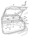
図3には、トノカバー10を備えた車両12が示されている。この車両12は2ボックスタイプのステーションワゴンであり、後部座席14とバックドア16との間のスペースがラッゲージルーム18として用いられている。このラッゲージルーム18には乗員の荷物20等が載置可能となっている。また、後部座席14のシートバックの上端部裏面側には、トノカバー10が配設されている。
トノカバー10は、巻取軸22とシート状部材としてのカバー24(シート状部材)とを備えている。カバー24の車両後方側端部には車幅方向に沿って、カバー24の幅より長い軸26が設けられている。軸26の幅方向両側部は、それぞれカバー24の幅方向両側部から突出しており、軸部材としての左右一対のストッパピン26A(軸部材)なっている、また、ストッパピン26Aは、車両内側側壁28におけるバックドア16の近傍に配設された左右一対の係止装置30にそれぞれ係止可能となっている。
トノカバー10の巻取軸22は、その軸方向が車両幅方向と一致するように配置されている。巻取軸22の内部には、トノカバー10の非使用時にカバー24を付勢力によって巻き取るための図示しない巻取装置が配設されている。従って、トノカバー10の使用時には、カバー24を巻取装置の付勢力に抗して車両後方(図3の矢印A方向)へ引き出し、ストッパピン26Aを係止装置30に係止するようになっている。
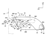
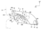
図1及び図2に示されるように、本実施形態では、係止装置30における導入路形成部材がデッキサイドトリム32(導入路形成部材)によって構成されている。なお、デッキサイドトリム32は車両のリヤサイドパネルの内側に配置され、車両内側側壁28(図3参照)を構成する内装材である。また、デッキサイドトリム32は車両前後方向に沿って配置される縦壁部32Aと、縦壁部32Aの車両後方側端から車幅方向外側へ湾曲された後壁部32Bと、を有している。デッキサイドトリム32の縦壁部32Aには車両前後方向に伸びる直線状の軸部材導入路34が形成されている。軸部材導入路34は、縦壁部32Aの上下方向中間部に形成されており、縦壁部32Aの前端に開口部34Aが形成され、縦壁部32Aの前後方向中間部が奥側端になる後端部34Bとなっている。なお、軸部材導入路34の幅は、ストッパピン26Aの軸径より僅かに大きく設定されており、ストッパピン26Aは軸部材導入路34に沿って車両前後方向へ移動可能となっている。
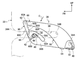
図2に示すように、係止装置30は、デッキサイドトリム34の車幅方向外側面に沿って隣接して配設された厚板状のカム38を備えている。カム38は、後端下部38Aが車幅方向に沿って配置された軸40によって、デッキサイドトリム34の後端下部34Cに車両下方向(図2の矢印C方向)と車両上方向(図2矢印D方向)とへ揺動可能に軸支されている。従って、カム38は軸部材導入路34の奥側となる車両後方側に軸支され、軸部材導入路34と交差する方向へ揺動可能となっている。また、カム38の前端下部には、第1当接面42が形成されている。
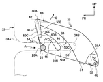
図4に示すように、第1当接面42はカム38の前端の上下方向中央部から後方下側に向かって僅かに前方側へ凸に湾曲した傾斜面となっており、傾斜角度はθ1となっている。カム38における第1当接面42の後方側には、係止溝44が形成されており、第1当接面42は、係止溝44の前方側(軸40と反対側)に形成されている。また、係止溝44はカム38の下端側が開口部となっており、開口部から前側上方に向かって傾斜した状態で伸びている。なお、図2に示すように、係止溝44の車幅方向外側端部は、カム38の車幅方向外側側壁部38Bで閉塞されている。
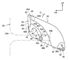
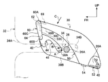
従って、図6に示すように、ストッパピン26Aが軸部材導入路34に沿って車両前方から車両後方(図6の矢印A方向)へ向かって移動することで、ストッパピン26Aがカム38の第1当接面42と摺動し、カム38が軸40を中心として上方(図6の矢印D方向)へ揺動するようになっている。その後、図7に示すように、ストッパピン26Aが第1当接面42に下端に達し、下端を通過すると、図8に示すように、カム38が軸40を中心として下方(図8の矢印C方向)へ揺動し、ストッパピン26Aが係止溝44に係止されるようになっている。
図4に示すように、カム38における係止溝44の後方側(軸40側)には、係止溝44の後壁部に連続して第2当接面46が形成されている。第2当接面46はカム38の後側下方に向かって傾斜しており、傾斜角度はθ2となっている。なお、本実施形態では、第1当接面42の傾斜角度はθ1と第2当接面46の傾斜角度θ2とが略等しくなっている(θ1≒θ2)。
従って、図9に示すように、ストッパピン26Aが、係止溝44から軸部材導入路34に沿って車両後方(図9の矢印A方向)へ向かって移動することで、ストッパピン26Aがカム38の第2当接面46と摺動し、カム38が軸40を中心として上方(図9の矢印D方向)へ揺動するようになっている。
なお、本実施形態では、第2当接面46が第1当接面42に対してカム38の揺動中心側に形成されており、カム38の揺動中心となる軸40と第2当接面46との距離が、軸40と第1当接面42との距離より短い。且つ、第1当接面42の傾斜角度はθ1と第2当接面46の傾斜角度θ2とが略等しくなっている(θ1≒θ2)。このため、ストッパピン26Aを第1当接面42に摺動させてカム38を上方に揺動するための操作力F1に比べて、ストッパピン26Aを第2当接面46に摺動させてカム38を上方に揺動するための操作力F2が大きくなる(F1<F2)。
図2に示すように、カム38における第2当接面46の後方側(軸40側)には、離脱路50の入口部50Aが形成されている。離脱路50は、カム38の下端の前後方向中央部に形成された入口部50Aから、カム38の前方上側に向かって僅かに上方側へ凸に湾曲した傾斜溝となっており、離脱路50の出口部50Bは、カム38の第1当接面42の上方に形成されている。また、離脱路50は、ストッパピン26Aが通過可能となっており、入口部50Aから出口部50Bに向かって溝幅W1が徐々に狭くなっている。なお、図2に示すように、離脱路50の車幅方向外側端部はカム38の車幅方向外側側壁部38Bで閉塞されている。
従って、図9に示すように、ストッパピン26Aが、係止溝44から軸部材導入路34に沿って車両後方(図9の矢印A方向)へ向かって移動することで、カム38が軸40を中心として上方(図9の矢印D方向)へ揺動するようになっている。その後、図10に示すように、ストッパピン26Aが第2当接面46に下端に達し、下端を通過すると、図11に示すように、ストッパピン26Aが離脱路50の入口部50Aに挿入され、カム38は軸40を中心として下方(図11の矢印C方向)へ揺動するようになっている。また、この状態で、作業者がカバー24の後端を把持する力を弱める、又はカバー24から手を離すと、トノカバー10の巻取軸22に設けられた巻取装置の付勢力によって、カバー24とともにストッパピン26Aが、前方(図11の矢印B方向)へ引き戻されるようになっている。
従って、図12及び図13に示すように、ストッパピン26Aは、軸部材導入路34に沿って車両前方(図12及び図13の矢印B方向)へ移動しつつ、離脱路50内を入口部50Aから出口部50Bに向かって移動するようになっている。このとき、ストッパピン26Aが離脱路50の前壁部50Cと摺動することで、カム38は、軸40を中心として下方(図12及び図13の矢印C方向)へ揺動するようになっている。
図1及び図2に示すように、軸40にはカム付勢機構としてのコイルスプリング52(カム付勢機構)が設けられている。コイルスプリング52は、カム38を下方(図1及び図2の矢印C方向)へ付勢している。なお、デッキサイドトリム34には、ストッパ54が突出形成されており、カム38はストッパ54に当接することで、コイルスプリング52の付勢力に抗して図1に示す基準位置に停止するようになっている。
従って、ストッパピン26Aが第1当接面42と摺動する際には、コイルスプリング52の付勢力に抗してカムが上方(図1及び図2の矢印D方向)へ揺動するようになっている。また、ストッパピン26Aが第2当接面46と摺動する際にも、コイルスプリング52の付勢力に抗してカムが上方(図1及び図2の矢印D方向)へ揺動するようになっている。
図1及び図2に示すように、離脱路50の出口部50Bには、出口部50Bを塞ぐ位置に開閉部材としてのフラップ60(開閉部材)が設けられている。フラップ60は上端部60Aが軸62によって、カム38の前端上部に車両後方(図1及び図2の矢印E方向)と車両前方(図1及び図2の矢印F向)とへ揺動可能に軸支されている。また、フラップ60の下端部60Bは、第1当接面42の上端に後方へ向かって形成された凹部64に係止可能とされている。
図4に示すように、フラップ60の下端部60Bが凹部64に係止された閉止位置で、フラップ60の前面60Cは後方下側に向かって傾斜しており、第1当接面42に連続している。
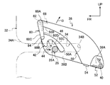
従って、図5に示すように、ストッパピン26Aが、軸部材導入路34に挿入され、軸部材導入路34に沿って車両後方(図5の矢印A方向)へ向かって移動を開始すると、ストッパピン26Aがフラップ60の前面60Cと摺動し、カム38が軸40を中心として上方(図5の矢印D方向)へ揺動するようになっている。その後、図6に示すように、ストッパピン26Aはカム38の第1当接面42と摺動するようになっている。
図1及び図2に示すように、フラップ60の軸62には、開閉部材付勢機構としてのコイルスプリング68(開閉部材付勢機構)が設けられている。コイルスプリング68は、フラップ60を後方(図1及び図2の矢印E方向)へ付勢している。なお、フラップ60は下端部60Bが凹部64に当接することで、コイルスプリング68の付勢力に抗して図1に示す閉止位置に停止するようになっている。
従って、図13及び図14に示すように、ストッパピン26Aが離脱路50の出口部50Bに達すると、ストッパピン26Aがフラップ60の後面60Dと摺動し、フラップ60をコイルスプリング68の付勢力に抗して、軸62を中心に前方(図13及び図14の矢印F方向)へ揺動するようになっている。このため、ストッパピン26Aが離脱路50の出口部50Bから抜け出ることができるようになっている。なお、図15に示すように、ストッパピン26Aがフラップ60から離れると、コイルスプリング68の付勢力によって、フラップ60は後方(図15の矢印E方向)へ揺動して閉止位置に戻るようになっている。
(作用・効果)
次に、本実施形態の作用と効果について説明する。
(トノカバー10を使用位置に引き出す場合)
次に、本実施形態の作用と効果について説明する。
(トノカバー10を使用位置に引き出す場合)
図3に示すように、本実施形態では、トノカバー10を使用位置に引き出す場合には、作業者がカバー24の後端部を把持してカバー24を巻取装置の付勢力に抗して引き出し、ストッパピン26Aを係止装置30に係止する。この際、図5に示すように、ストッパピン26Aを、デッキサイドトリム32の軸部材導入路34に挿入し、直線状の軸部材導入路34に沿って車両後方(図5の矢印A方向)へ移動する。これにより、ストッパピン26Aはフラップ60の前面60Cと摺動し、カム38がコイルスプリング52の付勢力に抗して軸40を中心として上方(図5の矢印D方向)へ揺動する。その後、図6に示すように、ストッパピン26Aがカム38の第1当接面42と摺動し、カム38がコイルスプリング52の付勢力に抗して軸40を中心としてさらに上方(図6の矢印D方向)へ揺動する。
さらに、ストッパピン26Aを直線状の軸部材導入路34に沿って車両後方へ移動すると、図7に示すように、ストッパピン26Aが第1当接面42の下端に達する。そして、ストッパピン26Aが第1当接面42の下端を通過すると、図8に示すように、カム38が軸40を中心として下方(図8の矢印D方向)へ揺動し、係止溝44に係止される。このため、ストッパピン26Aを軸部材導入路34に沿って車両後方へ直線状に移動することで、ストッパピン26Aが係止溝44に容易且つ確実に係止される。
(トノカバー10を格納位置に戻す場合)
次に、トノカバー10を格納位置に戻す場合には、ストッパピン26Aが、係止装置30のカム38の係止溝44に係止されている図8に示す状態で、作業者がカバー24の後端部を把持してカバー24を巻取装置の付勢力に抗して引き出す方向(車両後方)へ移動する。これにより、図9に示すように、ストッパピン26Aが、係止溝44から軸部材導入路34に沿って車両後方(図9の矢印A方向)へ向かって移動する。このため、ストッパピン26Aがカム38の第2当接面46と摺動し、カム38が軸40を中心として上方(図9の矢印D方向)へ揺動する。その後、図10に示すように、ストッパピン26Aが第2当接面46に下端に達し、下端を通過すると、図11に示すように、ストッパピン26Aが離脱路50の入口部50Aに挿入され、カム38は軸40を中心として下方(図11の矢印C方向)へ揺動する。
次に、トノカバー10を格納位置に戻す場合には、ストッパピン26Aが、係止装置30のカム38の係止溝44に係止されている図8に示す状態で、作業者がカバー24の後端部を把持してカバー24を巻取装置の付勢力に抗して引き出す方向(車両後方)へ移動する。これにより、図9に示すように、ストッパピン26Aが、係止溝44から軸部材導入路34に沿って車両後方(図9の矢印A方向)へ向かって移動する。このため、ストッパピン26Aがカム38の第2当接面46と摺動し、カム38が軸40を中心として上方(図9の矢印D方向)へ揺動する。その後、図10に示すように、ストッパピン26Aが第2当接面46に下端に達し、下端を通過すると、図11に示すように、ストッパピン26Aが離脱路50の入口部50Aに挿入され、カム38は軸40を中心として下方(図11の矢印C方向)へ揺動する。
この状態で、作業者がカバー24の後端を把持する力を弱める、又はカバー24から手を離すと、トノカバー10の巻取軸22に設けられた巻取装置の付勢力によって、カバー24とともにストッパピン26Aが、前方(図11の矢印B方向)へ引き戻される。このため、図12に示すように、ストッパピン26Aは直線状の軸部材導入路34に沿って車両前方(図12の矢印B方向)へ移動しつつ、離脱路50の内部を出口部50Bに向かって移動する。また、ストッパピン26Aが離脱路50の前壁部50Cと摺動することで、カム38は下方(図12の矢印C方向)へ揺動する。なお、コイルスプリング52の付勢力によっても、カム38は下方(図12の矢印C方向)へ揺動する。
次に、図13に示すように、ストッパピン26Aが離脱路50の出口部50Bに達すると、ストッパピン26Aがフラップ60の後面60Dと摺動し、図14に示すように、フラップ60をコイルスプリング68の付勢力に抗して、軸62を中心に前方(図14の矢印F方向)へ揺動する。このため、図15に示すように、ストッパピン26Aが、離脱路50の出口部50Bとデッキサイドトリム32の軸部材導入路34とから抜け出し、係止装置30から離れ、カバー24が付勢力によって巻取軸22に巻き取られる。また、ストッパピン26Aがフラップ60の後面60Dから離れると、コイルスプリング68の付勢力によって、フラップ60は後方(図15の矢印E方向)へ揺動して閉止位置に戻る。
以上のように、本実施形態では、ストッパピン26Aを係止装置30のカム38の係止溝44へ係止する操作と、ストッパピン26Aを係止溝44から解除し、係止装置30から離脱させる操作が、双方ともデッキサイドトリム32の軸部材導入路34に沿った直線移動となる。このため、ジグザグに移動させる従来構造の係止装置に比べて操作性が向上する。この結果、トノカバー10のカバー24を引き出す、または、収納する際の操作性が向上する。
また、本実施形態では、第2当接面46が第1当接面42に対してカム38の揺動中心側に形成されており、カム38の揺動中心となる軸40と第2当接面46との距離が、軸40と第1当接面42との距離より短くなっている。且つ、第1当接面42の傾斜角度はθ1と第2当接面46の傾斜角度θ2とが略等しくなっている(θ1≒θ2)。このため、ストッパピン26Aを第1当接面42に摺動させてカム38を上方に揺動するための操作力F1に比べて、ストッパピン26Aを第2当接面46に摺動させてカム38を上方に揺動するための操作力F2が大きくなる(F1<F2)。即ち、係止溝44から移動を開始したストッパピン26Aが第2当接面46と摺動してカム38を上方へ揺動する場合には、係止溝44に向かって移動するストッパピン26Aが第1当接面42と摺動してカム38を上方へ揺動する場合に比べて大きな操作力が必要になる。この結果、ストッパピン26Aが係止溝44に係止されたか否かの判断を操作力の増加によって容易に判断できるので、ストッパピン26Aを係止溝44に確実に係止することが可能になる。
また、本実施形態では、カム38がコイルスプリング52によって係止溝44がストッパピン26Aを係止する方向へ付勢されている。このため、ストッパピン26Aを係止溝44に確実に係止させることができる。
また、本実施形態では、ストッパピン26Aが離脱路50の出口部50Bを塞ぐ位置に設けられたフラップ60の前面60Cと摺動することによって、カム38の第1当接面42に案内される。このため、ストッパピン26Aが離脱路50に入ることがなく、係止溝44に容易かつ確実に案内される。また、フラップ60の後面60Dが離脱路50に沿って移動するストッパピン26Aと摺動することによって、フラップ60が離脱路50の出口部50Bを塞ぐ閉止位置から離脱路50の出口部50を開く開放位置へ揺動する。このため、ストッパピン26Aを係止装置30から確実に離脱させることができる。
また、本実施形態では、コイルスプリング68がフラップ60を離脱路50の出口部50Bを閉じる方向へ付勢している。このため、フラップ60によって離脱路50の出口部50Bを確実に閉じることができる。
また、本実施形態では、ストッパピン26Aがカバー24の車幅方向両端部にそれぞれ設けられており、これら一対のストッパピン26Aにそれぞれ対応して左右の係止装置30が設けられている。このため、横幅の広いトノカバー10のカバー24の幅方向両端部を容易に係止することができる。
また、上記実施形態では、カム付勢機構としてのコイルスプリング52によってカム38を付勢し、開閉部材付勢機構としてのコイルスプリング68によってフラップ60を付勢している。このため、ストッパピン26Aの移動方向(軸部材導入路34の方向)が車両前後方向以外、例えば、上下方向等の構成においてもカム38及びフラップ60が確実に作動する。
(その他の実施形態)
以上に於いては、本発明を特定の実施形態について詳細に説明したが、本発明は上記実施形態に限定されるものではなく、本発明の範囲内にて他の種々の実施形態が可能であることは当業者にとって明らかである。例えば、上記実施形態では、カム付勢機構としてのコイルスプリング52によって、カム38を付勢したが、これに代えて、コイルスプリング以外の板ばね等の他のカム付勢機構によって、カム38を付勢する構成としてもよい。また、カム付勢機構を除き、自重によりカム38が下方へ揺動する構成としてもよい。
以上に於いては、本発明を特定の実施形態について詳細に説明したが、本発明は上記実施形態に限定されるものではなく、本発明の範囲内にて他の種々の実施形態が可能であることは当業者にとって明らかである。例えば、上記実施形態では、カム付勢機構としてのコイルスプリング52によって、カム38を付勢したが、これに代えて、コイルスプリング以外の板ばね等の他のカム付勢機構によって、カム38を付勢する構成としてもよい。また、カム付勢機構を除き、自重によりカム38が下方へ揺動する構成としてもよい。
また、上記実施形態では、開閉部材付勢機構としてのコイルスプリング68によって、フラップ60を付勢したが、これに代えて、コイルスプリング以外の板ばね等の他の開閉部材付勢機構によって、フラップ60を付勢する構成としてもよい。また、開閉部材付勢機構を除き、自重によりフラップ60揺動する構成としてもよい。
また、上記実施形態では、導入路形成部材としてのデッキサイドトリム32に軸部材導入路34を形成したが、これに代えて、リヤサイドパネル等の他の導入路形成部材に軸部材導入路34を形成した構成としてもよい。また、カム38をデッキサイドトリム32に代えてリヤサイドパネル等の他の部材に軸支した構成としてもよい。
また、上記実施形態では、軸部材としての左右一対のストッパピン26Aを左右一対の係止装置30にそれぞれ係止する構成としたが、左右何れか一方のストッパピン26Aのみを左右何れか一方のみの係止装置30に係止する構成としてもよい。また、軸部材はストッパピン26Aに限定されず、軸部材導入路34を通過可能、係止溝44に係止可能、且つ離脱路50を通過可能であれば、軸形状の他の軸部材であってもよい。
また、上記実施形態では、離脱路50の出口部50Bに開閉部材としてのフラップ60を設けたが、開閉部材はフラップ60に限定されず、弾性変形可能な板ばねが離脱路50の出口部50Bを直接開閉する等の他の開閉部材としてもよい。また、離脱路50の出口部50Bに開閉部材を設けない構成とすることも可能である。なお、離脱路50の出口部50Bに開閉部材を設けない構成とした場合には、ストッパピン26Aを軸部材導入路34に挿入した際に、カム38を手動により上方へ僅かに揺動して、ストッパピン26Aがカム38の第1当接面42と摺動するようにすればよい。
また、上記実施形態では、第1当接面42の傾斜角度はθ1と、第2当接面46の傾斜角度はθ2とを略同じ(θ1≒θ2)としたが、これに代えて、第2当接面46の傾斜角度θ2を第1当接面42の傾斜角度θ1に比べて大きくして(θ1<θ2)もよい。この場合には、ストッパピン26Aを第1当接面42に摺動させてカム38を上方に揺動するための操作力F1に比べて、ストッパピン26Aを第2当接面46に摺動させてカム38を上方に揺動するための操作力F2がさらに大きくなる(F1<F2)。この結果、ストッパピン26Aが係止溝44に係止されたか否かの判断を操作力の増加によってさらに容易に判断可能となる。
また、上記実施形態では、カム38が軸40を中心に上下方向へ揺動する構成としたが、これに代えて、カム38がガイドレール等のガイド部材によって上下方向へ平行移動することで、ストッパピン26Aがカム38の第1当接面42と摺動し、係止溝44に係合し、且つ第2当接面46と摺動する構成としてもよい。
また、上記実施形態では、シート状部材としてのトノカバー10のカバー24を係止するために本発明の係止装置30を適用したが、本発明の係止装置30は、トノカバー10のカバー24以外のウインドシールドカーテン等の他のシート状部材にも適用可能である。また、本発明の係止装置30は、車両以外に、住宅等に使用されるカーテン等のシート状部材にも適用可能である。さらに、本発明の係止装置30は、シート状部材以外にも適用可能である。
Claims (7)
- 付勢力に抗して移動する軸部材を受け入れる直線状の軸部材導入路が形成された導入路形成部材と、
前記導入路形成部材に隣接して配置され、前記軸部材導入路と交差する方向へ移動可能とされたカムと、
前記カムに形成され、前記軸部材を係止位置に保持するための係止溝と、
前記カムに形成され、前記軸部材導入路に侵入した前記軸部材と摺動することで、前記カムを移動し、前記軸部材を前記係止溝に案内する第1当接面と、
前記カムに形成され、前記係止溝から抜け出した前記軸部材を受け入れる入口部と、前記軸部材を前記カムから分離させる出口部と、を備え、前記付勢力によって引き戻され前記軸部材導入路を逆走する前記軸部材が通過可能とされた離脱路と、
前記カムに形成され、軸部材導入路に沿って前記係止溝から移動する前記軸部材と摺動することで、前記カムを移動し、前記軸部材を前記係止溝から前記離脱路の入口部に案内する第2当接面と、
を有する係止装置。 - 前記カムは前記軸部材導入路の奥を揺動中心にして揺動可能とされており、前記カムの揺動中心と前記第1当接面との距離が、前記カムの揺動中心と前記第2当接面との距離より長く、前記軸部材が前記第2当接面と摺動して前記カムを揺動するために必要な力が、前記軸部材が前記第1当接面と摺動して前記カムを揺動するために必要な力より大きく設定されている請求項1に記載の係止装置。
- 前記カムを前記係止溝が前記軸部材を係止する方向へ付勢するカム付勢機構を有する請求項1または請求項2に記載の係止装置。
- 前記離脱路の出口部を塞ぐ位置に設けられ、前記軸部材導入路に侵入した前記軸部材と摺動することによって前記軸部材を前記第1当接面に案内すると共に、前記離脱路の入口部から出口部へ移動する前記軸部材と摺動することによって、前記離脱路の出口部を塞ぐ位置から前記離脱路の出口部を開く方向へ揺動する開閉部材を有する請求項1~3の何れか1項に記載の係止装置。
- 前記開閉部材を前記離脱路の出口部を閉じる方向へ付勢する開閉部材付勢機構を有する請求項4に記載の係止装置。
- 前記軸部材は巻取り方向へ付勢されたシート状部材に設けられている請求項1~5の何れか1項に記載の係止装置。
- 前記軸部材が前記シート状部材の幅方向両端部にそれぞれ設けられており、前記導入路形成部材と前記カムとが前記各軸部材にそれぞれに対応して設けられている請求項6に記載の係止装置。
Applications Claiming Priority (2)
| Application Number | Priority Date | Filing Date | Title |
|---|---|---|---|
| JP2011144554A JP2013011310A (ja) | 2011-06-29 | 2011-06-29 | 係止装置 |
| JP2011-144554 | 2011-06-29 |
Publications (1)
| Publication Number | Publication Date |
|---|---|
| WO2013001995A1 true WO2013001995A1 (ja) | 2013-01-03 |
Family
ID=47423895
Family Applications (1)
| Application Number | Title | Priority Date | Filing Date |
|---|---|---|---|
| PCT/JP2012/064478 Ceased WO2013001995A1 (ja) | 2011-06-29 | 2012-06-05 | 係止装置 |
Country Status (2)
| Country | Link |
|---|---|
| JP (1) | JP2013011310A (ja) |
| WO (1) | WO2013001995A1 (ja) |
Families Citing this family (1)
| Publication number | Priority date | Publication date | Assignee | Title |
|---|---|---|---|---|
| JP7347261B2 (ja) * | 2020-02-25 | 2023-09-20 | トヨタ紡織株式会社 | トノカバーの係止構造 |
Citations (2)
| Publication number | Priority date | Publication date | Assignee | Title |
|---|---|---|---|---|
| JP2003237470A (ja) * | 2002-02-13 | 2003-08-27 | Ashimori Ind Co Ltd | 車両用荷崩れ防止装置 |
| JP2009184526A (ja) * | 2008-02-06 | 2009-08-20 | Piolax Inc | トノカバー装置 |
-
2011
- 2011-06-29 JP JP2011144554A patent/JP2013011310A/ja not_active Withdrawn
-
2012
- 2012-06-05 WO PCT/JP2012/064478 patent/WO2013001995A1/ja not_active Ceased
Patent Citations (2)
| Publication number | Priority date | Publication date | Assignee | Title |
|---|---|---|---|---|
| JP2003237470A (ja) * | 2002-02-13 | 2003-08-27 | Ashimori Ind Co Ltd | 車両用荷崩れ防止装置 |
| JP2009184526A (ja) * | 2008-02-06 | 2009-08-20 | Piolax Inc | トノカバー装置 |
Also Published As
| Publication number | Publication date |
|---|---|
| JP2013011310A (ja) | 2013-01-17 |
Similar Documents
| Publication | Publication Date | Title |
|---|---|---|
| US9255429B2 (en) | 2-step guide hood latch apparatus for vehicle | |
| CN112848853B (zh) | 车门打开和关闭装置 | |
| CN101169026B (zh) | 汽车的滑动门构造 | |
| JP6342864B2 (ja) | 自動車用収納ボックス | |
| KR101786663B1 (ko) | 차량용 슬라이딩 도어 래치 | |
| JP5880480B2 (ja) | 車両用ドア構造 | |
| JP6385481B2 (ja) | 車両用駆動機構および車両用パネル移動方法 | |
| US11536058B2 (en) | Structure for connecting door latch cable to retractable outside door handle assembly for vehicle | |
| WO2013001995A1 (ja) | 係止装置 | |
| US10612280B2 (en) | Inside door handle structure | |
| JP3706111B2 (ja) | 車両のスライドドアの開閉装置 | |
| CN112840093A (zh) | 车辆用车门的操作杆装置 | |
| JP6738495B2 (ja) | 自動車用トノカバー装置 | |
| JP4306569B2 (ja) | 引き出し装置 | |
| JP6071056B2 (ja) | 車両用ドアラッチの操作中継装置 | |
| JP6616266B2 (ja) | 車両用収納装置 | |
| JP2011068309A (ja) | 収納ボックス | |
| JP5146237B2 (ja) | スライドドア装置 | |
| KR20160014257A (ko) | 자동차용 도어 체커 장치 | |
| JP6252180B2 (ja) | 車両用ドア構造 | |
| JP2004066857A (ja) | 車両のドア開閉装置 | |
| JP5041251B2 (ja) | 車両用収納装置 | |
| JP2008296672A (ja) | 車両用内装装置 | |
| KR20190050542A (ko) | 상하 개폐식 도어의 맵포켓 어셈블리 | |
| JP4415262B2 (ja) | 車両用収納装置 |
Legal Events
| Date | Code | Title | Description |
|---|---|---|---|
| 121 | Ep: the epo has been informed by wipo that ep was designated in this application |
Ref document number: 12804057 Country of ref document: EP Kind code of ref document: A1 |
|
| NENP | Non-entry into the national phase |
Ref country code: DE |
|
| 122 | Ep: pct application non-entry in european phase |
Ref document number: 12804057 Country of ref document: EP Kind code of ref document: A1 |