WO2013001652A1 - 空気入りタイヤ用トレッド - Google Patents
空気入りタイヤ用トレッド Download PDFInfo
- Publication number
- WO2013001652A1 WO2013001652A1 PCT/JP2011/065116 JP2011065116W WO2013001652A1 WO 2013001652 A1 WO2013001652 A1 WO 2013001652A1 JP 2011065116 W JP2011065116 W JP 2011065116W WO 2013001652 A1 WO2013001652 A1 WO 2013001652A1
- Authority
- WO
- WIPO (PCT)
- Prior art keywords
- tread
- phr
- filler
- pneumatic tire
- rubber composition
- Prior art date
Links
Images


Classifications
-
- B—PERFORMING OPERATIONS; TRANSPORTING
- B60—VEHICLES IN GENERAL
- B60C—VEHICLE TYRES; TYRE INFLATION; TYRE CHANGING; CONNECTING VALVES TO INFLATABLE ELASTIC BODIES IN GENERAL; DEVICES OR ARRANGEMENTS RELATED TO TYRES
- B60C11/00—Tyre tread bands; Tread patterns; Anti-skid inserts
- B60C11/03—Tread patterns
- B60C11/13—Tread patterns characterised by the groove cross-section, e.g. for buttressing or preventing stone-trapping
- B60C11/1353—Tread patterns characterised by the groove cross-section, e.g. for buttressing or preventing stone-trapping with special features of the groove bottom
-
- B—PERFORMING OPERATIONS; TRANSPORTING
- B60—VEHICLES IN GENERAL
- B60C—VEHICLE TYRES; TYRE INFLATION; TYRE CHANGING; CONNECTING VALVES TO INFLATABLE ELASTIC BODIES IN GENERAL; DEVICES OR ARRANGEMENTS RELATED TO TYRES
- B60C11/00—Tyre tread bands; Tread patterns; Anti-skid inserts
- B60C11/03—Tread patterns
- B60C11/04—Tread patterns in which the raised area of the pattern consists only of continuous circumferential ribs, e.g. zig-zag
- B60C11/042—Tread patterns in which the raised area of the pattern consists only of continuous circumferential ribs, e.g. zig-zag further characterised by the groove cross-section
-
- B—PERFORMING OPERATIONS; TRANSPORTING
- B60—VEHICLES IN GENERAL
- B60C—VEHICLE TYRES; TYRE INFLATION; TYRE CHANGING; CONNECTING VALVES TO INFLATABLE ELASTIC BODIES IN GENERAL; DEVICES OR ARRANGEMENTS RELATED TO TYRES
- B60C1/00—Tyres characterised by the chemical composition or the physical arrangement or mixture of the composition
- B60C1/0016—Compositions of the tread
-
- B—PERFORMING OPERATIONS; TRANSPORTING
- B60—VEHICLES IN GENERAL
- B60C—VEHICLE TYRES; TYRE INFLATION; TYRE CHANGING; CONNECTING VALVES TO INFLATABLE ELASTIC BODIES IN GENERAL; DEVICES OR ARRANGEMENTS RELATED TO TYRES
- B60C11/00—Tyre tread bands; Tread patterns; Anti-skid inserts
- B60C11/0008—Tyre tread bands; Tread patterns; Anti-skid inserts characterised by the tread rubber
-
- B—PERFORMING OPERATIONS; TRANSPORTING
- B60—VEHICLES IN GENERAL
- B60C—VEHICLE TYRES; TYRE INFLATION; TYRE CHANGING; CONNECTING VALVES TO INFLATABLE ELASTIC BODIES IN GENERAL; DEVICES OR ARRANGEMENTS RELATED TO TYRES
- B60C11/00—Tyre tread bands; Tread patterns; Anti-skid inserts
- B60C11/03—Tread patterns
- B60C11/13—Tread patterns characterised by the groove cross-section, e.g. for buttressing or preventing stone-trapping
- B60C11/1353—Tread patterns characterised by the groove cross-section, e.g. for buttressing or preventing stone-trapping with special features of the groove bottom
- B60C2011/1361—Tread patterns characterised by the groove cross-section, e.g. for buttressing or preventing stone-trapping with special features of the groove bottom with protrusions extending from the groove bottom
Definitions
- the present invention relates to a tread for a pneumatic tire, and more specifically, a flexible fence is formed in the main groove of the tread to reduce air column resonance noise and maintain drainage performance, and the flexible fence and the tread portion are worn to the same extent.
- the present invention relates to a tread for a pneumatic tire, and a pneumatic tire having such a tread.
- the air column resonance sound of the main groove formed in the tread of the tire is generated by resonance in the pipe (air column) formed by the main groove and the road surface, and the resonance frequency is formed between the road surface and the road surface. Depends on the length of the main air column.
- This air column resonance appears in the form of noise inside and outside the vehicle, and often has a peak around 1 kHz that easily reaches the human ear.
- a so-called flexible fence that is, a projection, extends from the groove wall and bottom of the main groove and blocks all or most of the main groove to form the main groove.
- the flow of water that has entered the main groove is also blocked. Since the drainage of water intervening with the road surface is reduced, the steering stability on a wet road surface is reduced.
- FIG. 4 of Patent Document 1 three groove fences 3 (flexible fences) respectively extending from the opposite groove walls and the groove bottom in the groove are arranged in the main groove with a gap between each other. There is disclosed a technique that achieves both reduction of resonance noise and drainage.
- the partition wall 30 (flexible fence) extending from the groove bottom in the main groove is arranged so that most of the main groove opening is not in contact with the groove wall.
- the thickness of the flexible fence in the tire circumferential direction is thin and easily deformed in order to make the flexible fence function. Therefore, depending on the material used, when traveling, the flexible fence that is easily deformed is less likely to be worn than the tread portion, and there is a difference in the amount of wear between the flexible fence and the tread portion. Due to the difference in the amount of wear, the flexible fence protrudes from the surface of the tread portion (the surface of the tread that forms the tread surface), and from the tread surface during traveling. There is a problem that the flexible fence hits the road surface and noise is generated. The generation of such abnormal noise is contrary to the original role of the flexible fence described above, which is to reduce noise by reducing air column resonance. Further, there is a problem that the flexible fence is worn or damaged at an early stage due to an unintended portion of the flexible fence contacting the road surface due to the protrusion from the tread portion of the flexible fence.
- An object of the present invention is to provide a tread for a pneumatic tire that can suppress a reduction in the effect of reducing air column resonance noise caused by the above, and a pneumatic tire having the tread.
- the present invention provides a tread for a pneumatic tire formed of a rubber composition that comes into contact with a road surface when the tire rolls, and has a bottom surface and two opposing wall surfaces and is deep.
- a tread portion formed with at least one main groove having a thickness D and a width W, and a plurality of flexible fences having a thickness E and blocking at least 70% of a cross-sectional area of the main groove.
- a plurality of flexible fences extending in the groove and arranged at intervals so as to exist in the main groove in the tread surface when the tire rolls, and the plurality of flexible fences are at least It is formed of a rubber composition for a fence different from the rubber composition of the tread part, and the rubber composition for a fence of a flexible fence is more than twice the wear index of the rubber composition of the tread part.
- Filler A which is a nanoparticle having an average
- a filler B greater than 50 phr wherein the particles of the filler are fine particles having a median particle size (weight average) greater than 1 ⁇ m It is characterized in that it contains a filling composition based on filler B.
- the present invention is formed in the main groove, blocks at least 70% of the cross-sectional area of the main groove, and exists at least one in the main groove in the tread surface when the tire rolls.
- the length of the air column in the main groove formed with the road surface is changed with a flexible fence arranged at a certain interval, compared with the case where the flexible fence is not formed, and the peak of the air column resonance sound is changed by humans. It is easy to remove the frequency band that can easily reach the ear, and as a result, noise caused by air column resonance is improved.
- the rubber composition for a fence contains fine particles (filler B) having a median particle size (weight average) larger than 1 ⁇ m and exhibiting a higher wear index than the rubber composition forming the tread portion. Because it contains more than 50phr, the flexible fence can be worn as much as the tread.
- fine particles (filler B) having a median particle size (weight average) larger than 1 ⁇ m are also called non-reinforcing fillers and have no or little reinforcing properties.
- the wear index increases, and the wear rate of the rubber composition containing such fine particles (filler B) increases. It is preferable that such fine particles (filler B) are not or hardly used in the tread portion, for example, less than 40 phr, more preferably less than 30 phr.
- fillers B examples include chalk, natural silicate, precipitated silica, alumina, fillers obtained by chemical synthesis, barium sulfate salts, metal oxides (Mg, Zn, Al And inorganic fillers such as mixtures thereof, and organic fillers such as short fibers, thermoplastic fibers, biodegradable compounds, cellulose derivatives, and mixtures thereof.
- the flexible fence when the flexible fence is in direct contact with the road surface while passing through the tread surface during rolling of the tire, the ground force is contacted between the road surface and the flexible fence due to the reaction force received when the tip of the flexible fence contacts the road surface. causes pressure and slip.
- the wear index of the rubber composition for the fence is larger than the wear index of the rubber composition of the tread portion, even if the ground pressure and the slip amount are reduced due to the deformation of the flexible fence, it is effective.
- the flexible fence can be worn to the same extent as the wear amount of the tread portion.
- the wear index of the rubber composition for a fence is made smaller than twice the wear index of the rubber composition of the tread part, the ground pressure generated when the flexible fence contacts the road surface and the amount of slippage are small. It is difficult to wear, and the flexible fence cannot be worn as much as the tread portion.
- This wear index more than twice this is the tread for pneumatic tires that the present inventors wear to the same extent as the tread portion of the flexible fence while reducing the air column resonance noise and maintaining the drainage performance. Is the numerical value found as appropriate in the process of evaluating such actions (especially drainage performance, flexible fence wear performance), and if the numerical value is within the above range (twice or more), It has been found by analysis and experiment that the above action can be obtained effectively.
- the “groove” is a width and depth formed by connecting two opposing surfaces (wall surfaces) that do not come into contact with each other under normal use conditions by other surfaces (bottom surfaces). A space that has
- main groove refers to a groove having a relatively wide width among various grooves formed in the tread, which mainly handles fluid drainage.
- the main groove means a groove extending in the tire circumferential direction in a straight line, zigzag shape or wave shape in many cases, but has a relatively wide width mainly extending the drainage of the fluid extending at an angle with respect to the tire rotation direction. Grooves with are also included.
- Thread surface refers to the surface area of the tread that comes into contact with the road surface when the tire is mounted on the applicable rim specified by the following industrial standards, filled with the rated internal pressure, and loaded with the rated load. Say.
- the “standard” is defined by an industrial standard effective in the region where the tire is produced or used.
- the industrial standard is “STANDARDS MANUAL” of ETRTO (The European Tyre and Rim Technical Organization) in Europe, and TRA (THE TIRE AND RIMCASSOCIATION IN.
- the tire association (JATMA) "JATMA YEAR BOOK”.
- “applicable rim” refers to a rim defined in these standards depending on the tire size
- “rated internal pressure” refers to an air pressure defined in accordance with the load capacity in these standards.
- “Rated load” refers to the maximum mass allowed to be applied to a tire in these standards.
- the “wearability of the rubber composition” refers to the wear volume of the rubber composition obtained in the Akron wear test measured according to JIS K6264-1 and JIS K6264-2.
- the wear volume of the rubber composition is determined from the difference in mass before and after the main test operation of the vulcanized rubber test piece using an Akron abrasion tester based on the above-mentioned standard.
- the number of revolutions of the grinding wheel is 500 for the preliminary operation and 3000 for the main test, and a tilt angle of 15 degrees is given between the test piece and the grinding wheel.
- the specimen is pressed against the grinding wheel with an applied force of 27.0 N, and the rotational speed of the specimen is 100 revolutions per minute.
- the “wear index” is an index of the above “wear property of rubber composition”.
- This “wear index” is provided to compare the wear properties of a plurality of rubber compositions with each other. From the results obtained in the wear test described above, the wear properties of a given rubber composition are used as a reference. Is a numerical value obtained by converting the numerical value of 1.00, for example, to 1.00, and calculating the abrasion resistance value of the rubber composition to be compared at the same conversion ratio. When the value of the wear index is twice, it indicates that the rubber composition to be compared wears twice as fast as the reference rubber composition.
- the content of various components of the rubber composition is expressed in phr (parts by mass per 100 parts by mass of elastomer or rubber). Furthermore, unless otherwise specified, the ratio (percentage,%) represents weight%, and the interval represented by “between a and b” is larger than a and smaller than b (not including upper and lower limit values). In addition, the interval represented by “from a to b” represents a or more and b or less (including upper and lower limit numerical values).
- “a“ diene ”elastomer or rubber” is an elastomer (at least partially derived from a diene monomer (a monomer having two carbon-carbon double bonds that are not conjugated or conjugated)). Or several elastomers), ie homopolymers or copolymers.
- the diene elastomer is selected from the group consisting of polybutadiene (BR), polyisoprene (IR), natural rubber (NR), butadiene copolymers, isoprene copolymers and blends of these elastomers.
- the diene elastomer is selected from the group consisting of natural rubber, polyisoprenes, polybutadienes having a cis-1,4 unit content of more than 90%, butadiene / styrene copolymers and blends of these elastomers.
- the filler A contains carbon black.
- Suitable carbon blacks are all types of carbon blacks, especially HAF, ISAF or SAF type blacks ("tire grade" blacks) commonly used in tire treads.
- HAF high-density carbon black
- ISAF ISAF
- SAF type blacks Tire grade blacks
- 100, 200 or 300 series reinforcing carbon blacks such as blacks N115, N134, N234, N326, N330, N339, N347 and N375 ( ASTM class).
- the filler A contains an inorganic filler.
- “Reinforcing inorganic filler” as used herein means any inorganic or mineral filler, regardless of its color and its origin (natural or synthetic), such filler being carbon Also known as “white filler”, “light filler” or “non-black filler” in contrast to black, and as such, the tire can be used without any means other than intermediate coupling agents. It is possible to reinforce the rubber composition used for the manufacture, i.e. it can be replaced in the usual tire grade carbon black and its reinforcing function.
- Such fillers are characterized by the presence of hydroxyl (—OH) groups on their surface, as is generally known.
- Suitable reinforcing inorganic fillers are in particular siliceous type mineral fillers, in particular silica (SiO2), or aluminous type mineral fillers, in particular alumina (Al2O3).
- the silica used may be any reinforcing silica known to those skilled in the art, in particular a BET surface area both in the range of less than 450 m 2 / g, preferably 30 to 400 m 2 / g, more preferably 60 to 300 m 2 / g. Any precipitated or calcined silica having a CTAB specific surface area can be used.
- Highly dispersible precipitated silicas may include, for example: silicas from Degussa Ultrasil 7000 and Ultrasil 7005; silicas from Rhodia Zeosil 1165MP, 1135MP and 1115MP; PPG Silica from the company Hi-Sil EZ150G; silicas from Huber Zeopol 8715, 8745 or 8755.
- silicas from Degussa Ultrasil 7000 and Ultrasil 7005 may include, for example: silicas from Degussa Ultrasil 7000 and Ultrasil 7005; silicas from Rhodia Zeosil 1165MP, 1135MP and 1115MP; PPG Silica from the company Hi-Sil EZ150G; silicas from Huber Zeopol 8715, 8745 or 8755.
- functional coupling agents or binders
- bifunctional organosilanes or polyorganosiloxanes in particular bifunctional organosilanes or polyorganosiloxanes.
- the inorganic filler contained in the filler A is preferably silica.
- the reinforcing filler a mixture of an organic filler such as carbon black and a reinforcing inorganic filler such as silica can be used.
- the amount of filler A is between 50 phr and 200 phr. Also more preferably, the amount of filler A is between 60 phr and 140 phr.
- the average particle size (weight average) of the nanoparticles of the filler A is smaller than 500 nm, preferably an average particle size between 20 nm and 200 nm, more preferably an average particle size between 20 nm and 150 nm.
- the average particle size of the nanoparticles indicated by d W (weight average), after dispersion by ultrasonic deagglomeration of the filler to be analyzed in water or surfactant-containing aqueous solution is measured as usual.
- d W weight average
- the measurement is carried out according to the following operating method using an XDC (X-ray disc centrifuge) X-ray centrifugal sedimentation rate meter sold by Brookhaven Instruments.
- a suspension consisting of 3.2 g of an inorganic filler test specimen to be analyzed in 40 ml of water, 60% of a 1500 W ultrasonic probe (1.91 cm (3/4 inch) Vibracell sonicator sold by Bioblock) Prepare by operating for 8 minutes at power (ie 60% away from maximum “power control” position). After sonication, 15 ml of suspension is introduced into the rotating disk.
- n i the particle size or number of objects in the diameter group d i ).
- this procedure is carried out with an aqueous solution containing 15% by volume ethanol and 0.05% by volume nonionic surfactant. The measurement is performed with a DCP type centrifugal light sedimentation rate meter (a disk centrifugal light sedimentation rate meter sold by Brookhaven Instruments).
- a suspension containing 10 mg carbon black was placed in a 40 ml aqueous solution containing 15% ethanol and 0.05% nonionic surfactant by a 600 W ultrasound probe (1.27 cm (1/27 sold by Bioblock). 2 inches) Vibracell sonicator) is pre-prepared by operating for 10 minutes at 60% power (ie 60% of the highest “tip amplitude”).
- Vibracell sonicator a density gradient consisting of 15 ml water (containing 0.05% nonionic surfactant) and 1 ml ethanol is injected into a sedimentation velocimeter disk rotating at 8000 rpm to form a “step gradient”
- 0.3 ml of carbon black suspension is injected onto the gradient surface.
- the mass distribution and weight average particle size d W of the particle size is calculated by sedimentometer software as described above.
- the filler B is selected from the group consisting of inorganic fillers, organic fillers and mixtures thereof.
- the amount of filler B is between 60 phr and 300 phr, more preferably between 90 phr and 300 phr, even more preferably between 140 phr and 300 phr.
- the median particle size (weight average) of the filler B is between 1 ⁇ m and 200 ⁇ m, more preferably between 5 ⁇ m and 100 ⁇ m.
- particle size analysis by mechanical screening can simply be used.
- the operation changes the mesh size of a specified amount of sample (eg 200g) on a vibrating table with various screen diameters (eg 1000,800,630,500,400, ..., 100,80,63 ⁇ m according to progressive ratio 1.26) Screening) for 30 minutes.
- the excess size collected on each screen is weighed with a precision balance, and from this we estimate the percentage of excess size at each mesh diameter relative to the total mass of the material, and finally the median particle size (or apparent median by mass) Diameter) or average particle size (or apparent average diameter) is calculated from the particle size distribution histogram in a known manner.
- the inorganic filler of the filler B is chalk, natural silicate (for example, kaolin, talc, mica), precipitated silica, alumina, a filler obtained by chemical synthesis (for example, Mg, Al, Selected from the group consisting of Ca silicate, silicoaluminate hydrate, calcium carbonate precipitate), barium nitrate, metal oxides (eg Mg, Zn, Al) and mixtures thereof.
- the organic filler of the filler B is a short fiber, a thermoplastic fiber, a biodegradable compound (for example, polyesteramide, modified starch, chitin, chitosan, polylactic acid), a cellulose derivative (for example, cellulose acetate). , Lignin) and mixtures thereof.
- a biodegradable compound for example, polyesteramide, modified starch, chitin, chitosan, polylactic acid
- a cellulose derivative for example, cellulose acetate. , Lignin
- the rubber composition for a fence preferably includes a plasticizing system, and more preferably, the plasticizing system is selected from the group consisting of a liquid plasticizer, a hydrocarbon resin, and a mixture thereof.
- a plasticizing system is selected from the group consisting of a liquid plasticizer, a hydrocarbon resin, and a mixture thereof.
- Any extender oil either aromatic or non-aromatic, can be used, ie any liquid plasticizer known for its plasticizing properties on diene elastomers. At normal temperature (23 ° C.), these plasticizers or oils are viscous liquids. On the contrary, plastic hydrocarbon resins are solid at normal temperature because of their origin.
- Liquid plasticizers are naphthenic oil, paraffinic oil, MES (Medium Extracted Solvates) oil, TDAE (Treated Distillate Aromatic Extracts) oil, mineral oil, vegetable oil, ether plasticizer, ester plasticizer, phosphate plasticizer, sulfonate plasticizer And a group consisting of a mixture thereof.
- the amount of liquid plasticizer is between 2 phr and 60 phr, more preferably between 3 phr and 40 phr, even more preferably from 5 phr to 20 phr.
- the composition of the present invention is a solid plasticizer (at 23 ° C.), for example, International Publication Nos. WO 2005/087859, WO 2006/061064, and WO 2007.
- Hydrocarbon resins are polymers well known to those skilled in the art and are inherently miscible in the diene elastomer composition when additionally described as being “plasticizing”.
- the hydrocarbon-based resins can be aliphatic or aromatic or of aliphatic / aromatic type, i.e. can be based on aliphatic and / or aromatic monomers.
- the hydrocarbon-based resin can be natural or synthetic.
- the plasticizing hydrocarbon resin is a cyclopentadiene (abbreviated as CPD) or dicyclopentadiene (abbreviated as DCPD) homopolymer or copolymer resin, a terpene homopolymer or copolymer. selected resins, C 5 fraction homopolymer or copolymer resins, C 9 fraction homopolymer or copolymer resins, and from the group consisting of mixtures of these resins
- the amount of the plasticized hydrocarbon-based resin is preferably between 2 phr and 60 phr, more preferably between 5 phr and 50 phr, and further preferably from 3 phr to 40 phr.
- the total amount of the plasticizing system for example, the amount of the liquid plasticizer added to the solid hydrocarbon resin is preferably between 40 phr and 100 phr, more preferably from 50 phr to 80 phr.
- the thickness E of the flexible fence is not less than 0.3 mm and not more than 1.0 mm.
- the flexible fence can be worn to the same extent as the tread portion. That is, if the thickness of the flexible fence is made smaller than 0.3 mm, the flexible fence collapses due to air pressure due to a decrease in the dimensional rigidity of the flexible fence, which may reduce the effect of reducing air column resonance noise. . In addition, such a fall makes it difficult for the flexible fence to come into contact with the ground within the tread surface, so that the speed of wear of the flexible fence is significantly reduced relative to the speed of wear of the tread. There is a risk of protruding. On the other hand, if the thickness of the flexible fence is larger than 1.0 mm, the opening ratio of the cross section of the main groove when the flexible fence falls into the main groove becomes small, and the drainage performance may be deteriorated.
- the flexible fence can be worn to the same extent as the tread portion while reducing the air column resonance noise and maintaining the drainage performance.
- FIG. 2 is an enlarged cross-sectional view of a tread for a pneumatic tire viewed along line II-II in FIG.
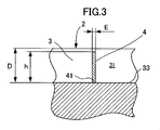
- FIG. 3 is an enlarged cross-sectional view of the tread for a pneumatic tire viewed along line III-III in FIG. 1.
- FIG. 3 is an enlarged cross-sectional view of the tread for a pneumatic tire shown along the line II-II in FIG. 1, similar to FIG. 2, schematically showing a state where the vehicle is traveling on a wet road surface.
- FIG. 4 is an enlarged cross-sectional view of the tread for a pneumatic tire shown along the line III-III in FIG. 1, similar to FIG.
- FIG. 4 is an enlarged cross-sectional view of the tread for a pneumatic tire shown along the line III-III in FIG. 1, similar to FIG. 3, schematically showing a state where the groove depth of the tread portion is worn by about 30%. It is.
- FIG. 1 is a diagram schematically showing a tread portion of a pneumatic tire according to an embodiment of the present invention.
- FIG. 2 is an enlarged view of the tread portion of the pneumatic tire taken along line II-II in FIG.
- FIG. 3 is a cross-sectional view
- FIG. 3 is an enlarged cross-sectional view of the tread portion of the pneumatic tire taken along line III-III in FIG.
- symbol 1 shows the tread 1 for pneumatic tires by this embodiment
- This tread 1 for pneumatic tires has the tread part 2 and the flexible fence 4 mentioned later.
- the main groove 3 has three surfaces, that is, opposing wall surfaces 31 and 32 and a bottom surface (bottom portion) 33.
- the tire size in this example is 225 / 55R16, and the tire rotation direction of the tread portion 2 is not defined.
- the opposing wall surfaces 31 and 32 each extend perpendicular to the tire radial direction, the groove width W is 14.5 mm, and the groove depth D is 8.0 mm.
- the tread tread surface 5 when the tire is filled with the rated internal pressure and the rated load is applied, and the tread tread length L at that time are shown.
- the applicable rim of this size is 7 J
- the rated internal pressure is 250 kPa
- the rated load is 690 kg
- the tread length L is 143 mm.
- each main groove 3 passing through the tread tread surface 5 forms an air column with the road surface, and the resonance frequency of the main groove 3 is that of the air column thus formed.
- a flexible fence 4 is provided in the main groove 3 as shown in FIGS. 1 to 3 in order to change the frequency of the air column resonance sound by changing the length of the air column.
- the installation interval P of each flexible fence 4 formed in the same main groove 3 is such that at least one flexible fence is always present in the tread surface 5 of each main groove 3 during tire rolling. Thus, the interval is shorter than the tread length L.
- the flexible fence 4 has its base 41 connected to the groove bottom 33 of the main groove 3 as shown in FIG. Are provided so as to extend in the tire radial direction (perpendicular to the tire rotation axis). Moreover, as shown in FIG. 2, the side part 42 of the both sides of the flexible fence 4 has the predetermined clearance gap with the wall surfaces 31 and 32 which the main groove 3 opposes the whole except the connection part (33) mentioned above. It is provided as follows.
- the flexible fence 4 is formed to extend in a direction perpendicular to the direction in which the main groove 3 extends.
- the flexible fence 4 has a rectangular cross-sectional shape, and the rectangular cross-section has a width l (see FIG. 2) and a thickness E (see FIG. 3).
- the flexible fence 4 is formed in a rectangular shape when viewed from the longitudinal direction of the main groove 3 (in front view), and as shown in FIGS. It has a slightly lower height h.
- the flexible fence 4 is formed so as to block at least 70% of the cross-sectional area of the main groove 3, and is formed so as to collapse due to water pressure mainly by a liquid such as water flowing in the main groove 3.
- the thickness E of the flexible fence 4 is 0.6 mm.
- the height h and width l of the flexible fence 4 are such that the depth D8 of the main groove 3 is such that about 87% of the cross-sectional area of the main groove 3 is blocked.
- the height h is 7.0 mm and the width l is 13.5 mm with respect to 0.0 mm and the groove width W 14.5 mm.
- the flexible fence 4 has a rectangular shape having a height h of about 5.6 mm or more so as to block at least 70% of the cross-sectional area of the main groove 3. Also good.
- the groove width W and the groove depth D of the tire main groove 3 are changed, the width l and the height h of the flexible fence 4 are also changed accordingly, and the main groove 3 is changed accordingly. It is sufficient to block at least 70% of the cross-sectional area.
- the flexible fence 4 is made of a rubber composition for a fence different from the tread 2, and the rubber composition for the fence generates a faster wear rate than the tread 2.
- Non-reinforcing particles which are not usually contained in the rubber composition constituting No. 2 and have a median particle size (weight average) of 1 ⁇ m or more and which are fine particles in an amount larger than 50 phr (in this embodiment, 200 phr) Contains a filler.
- non-reinforcing fillers include, for example, chalk, natural silicates, precipitated silica, alumina, fillers obtained by chemical synthesis, barium sulfate salts, metal oxides (Mg, Zn, Al, etc.) and Inorganic fillers such as mixtures thereof, organic fillers such as short fibers, thermoplastic fibers, biodegradable compounds, cellulose derivatives and mixtures thereof can be used.
- the rubber composition constituting the tread 2 contains such fine particles (non-reinforcing)
- the fine particles (non-reinforcing) is a very small amount, and preferably the difference in content with the rubber composition for fences is 20 phr. More preferably, it is 30 phr or more.
- the rubber composition for a fence contains 50 phr or more of such fine particles (non-reinforcing)
- the rubber composition constituting the tread preferably contains less than 30 phr of such fine particles (non-reinforced). Preferably it contains less than 20 phr.
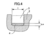
- FIG. 4 is an enlarged cross-sectional view showing a state where the pneumatic tire tread is traveling along a wet road surface as viewed along the line II-II in FIG. 1
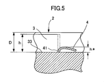
- FIG. 5 is a cross-sectional view taken along the line III-III in FIG. It is an expanded sectional view which shows the state in driving
- the flexible fence 4 formed of a rubber composition for a fence different from the tread 2 as described above passes through the main groove 2 when traveling on a wet road surface. It collapses or bends mainly due to the water pressure generated by a liquid such as water, and as a result, its height decreases to h *, and the main part of the main groove 3 is opened and drained by the decrease in the height. Sex is secured.
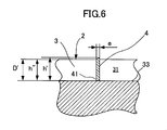
- FIG. 6 is an enlarged cross-sectional view of the pneumatic tire tread as seen along the line III-III in FIG. 1 with the groove depth worn about 30%.
- FIG. 6 shows a state in which after traveling a predetermined distance, the groove depth D of the main groove 3 is reduced to D ′ shallower than the initial height h of the flexible fence 4 due to wear.
- the flexible fence 4 formed of a rubber composition for a fence different from the tread 2 is worn at an angle at the tip portion that contacts the road surface after traveling a predetermined distance, and its height is h ′ on the high side and the low side.
- the height h ′′ on the lower side is about the same as the depth D ′ of the main groove 3.
- the rubber composition for fences will be a part (for example, mentioned above) of the bottom part 33 of the main groove 3 to which the flexible fence 4 is connected. You may use for a connection part (33) (refer FIG. 2, FIG. 3)) or all (not shown). In such a case, since not only the flexible fence 4 but also the bottom 33 of the main groove 3 is formed of the same rubber composition for a fence, the manufacturing process can be simplified.
- the flexible fence 4 formed of the rubber composition for a fence may be divided into a plurality of parts or the main groove 3 as long as it has the above-described action. It is connected to both or one of the opposing wall surfaces 31 and 32 and is formed to extend in the groove width direction, or is connected to the flexible fence connected to the wall surfaces 31 and 32 and the bottom 33 of the main groove 3 in this way.
- the flexible fence 4 may be combined (not shown).
- the rubber composition for the fence and the rubber composition constituting the tread part are preferably placed in a suitable mixer in two successive production stages known to those skilled in the art, namely between 110 ° C. and 190 ° C., preferably 130 ° C. And a first stage thermomechanically processed or mixed at a high temperature with a maximum temperature between 180 ° C. and 180 ° C. (referred to as the “non-production” stage), and thereafter typically below 110 ° C., eg 40 Manufactured using a second machining stage (referred to as the “production” stage) at a lower temperature between 0 ° C. and 100 ° C., the crosslinking system is incorporated in this finishing stage (production stage).
- the method for producing a rubber composition for a fence includes, for example, at least the following steps: In the first ("non-production") stage, at least one reinforcing filler (the particles are nanoparticles having an average particle size (weight average) of less than 500 nm), more than 50 phr of non-reinforcing filler
- the agent (the particles are fine particles having a median particle size (weight average) larger than 1 ⁇ m) is mixed in or mixed into the diene elastomer, and the mixture obtained by the mixing is mixed at least once.
- thermomechanically until reaching a maximum temperature between °C and 190 °C; Cooling the mixture to a temperature below 100 ° C; Then, in the second (“production”) stage, incorporating the crosslinking system; Mixing the mixture until a maximum temperature below 110 ° C is reached.
- the non-production stage described above is carried out in a single thermomechanical process, during which first all the essential base components (diene elastomer, reinforcing filler and optionally Coupling agents, non-reinforcing fillers and plasticizing systems) are first introduced into a suitable mixer, such as a standard closed mixer, and then secondly, for example after mixing for 1 to 2 minutes, after the crosslinking system Introducing other additives, optional coatings or complementary processing aids.
- the total mixing time in this non-production stage is preferably between 1 and 15 minutes.
- the crosslinking system is introduced into an open mixer such as an open mill maintained at a low temperature (eg between 40 ° C. and 100 ° C.).
- a low temperature eg between 40 ° C. and 100 ° C.
- the mixture is then mixed for a few minutes, eg 2-15 minutes (production stage).
- the crosslinking system is preferably a vulcanization system based on sulfur and an accelerator.
- Any compound that can act as a vulcanization accelerator for diene elastomers in the presence of sulfur especially 2-mercaptobenzothiazyl disulfide (abbreviated “MBTS”), N, N-dicyclohexyl-2-benzothiazylsulfur Fenamide (abbreviated as “DCBS”), N-tert-butyl-2-benzothiazylsulfenamide (abbreviated as “TBBS”), N-tert-butyl-2-benzothiazylsulfenimide (“ A compound selected from the group consisting of TBSI ”) and mixtures of these compounds may be used.
- a sulfenamide type primary accelerator is used.
- Various known secondary accelerators or vulcanization activators such as zinc oxide, stearic acid, guanidine derivatives (especially diphenylguanidine), etc. are added to the vulcanization system during the first non-production stage described above and / or It can be added during the production phase described above.
- the sulfur content is, for example, between 0.5 phr and 3.0 phr, and the primary accelerator content is between 0.5 phr and 5.0 phr.
- the final composition thus obtained is then calendered, for example into a sheet or plaque, or extruded, for example, in the form of a rubber-shaped element that can be used as a tire tread.
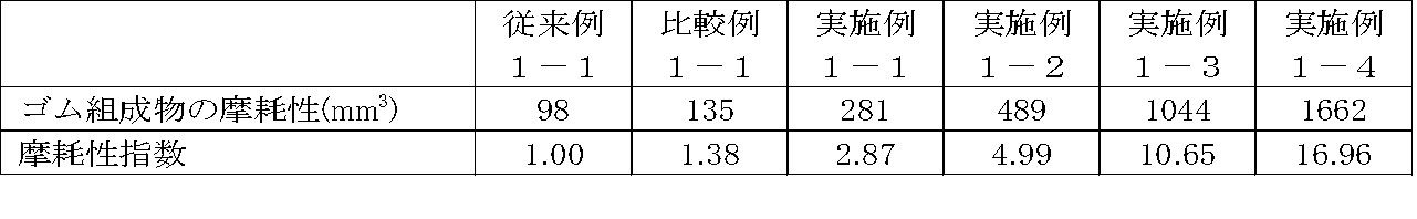
- Table 1 the content of various components produced using silica as a reinforcing filler is shown in phr.
- a rubber composition (Examples 1-1, 1-2, 1-3, 1-4) and a rubber composition not related to the present invention (Comparative Example 1-1) were prepared.
- Each of these six rubber compositions contains 100 phr silica as a reinforcing filler, and the four example rubber compositions and one comparative rubber composition contain at least 10 phr of chalk particulate.
- the rubber composition of Conventional Example 1-1 described above is manufactured by a conventional manufacturing method and used for the tread portion 2 of the tread according to the present invention. That is, in Tables 1 to 4 below, each value of the rubber composition of Conventional Example 1-1 and each value of the rubber composition of Examples 1-1, 1-2, 1-3, and 1-4
- the rubber composition of the tread portion 2 of the tread according to the present invention can be compared with the rubber composition of the flexible fence 4 of the tread according to the present invention (for example, “abrasion index”). is there.
- Table 2 shows the measured values of the wear of each manufactured rubber composition and the wear index calculated from the measurement results based on Conventional Example 1-1 (1.00). Yes. The larger the value of the wear index, the faster the wear rate of the rubber composition.
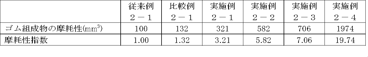
- Example 3 the content of various components produced using carbon black as a reinforcing filler is shown in phr.
- One conventional rubber composition (conventional example 2-1) used as a tread rubber composition, four rubber compositions according to the present invention (Examples 2-1, 2-2, 2- 3, 2-4) and a rubber composition not related to the present invention (Comparative Example 2-1) were prepared.
- Each of these six rubber compositions contains 105 phr carbon black as a reinforcing filler, and the four example rubber compositions and one comparative rubber composition contain at least 10 phr chalk. Fine particles are further contained as a non-reinforcing filler.
- Table 4 shows the measured values of the wear of each manufactured rubber composition, and the wear index based on Conventional Example 2-1 (1.00) calculated from the measurement results. Yes. The larger the value of the wear index, the faster the wear rate of the rubber composition.
- Examples used for flexible fences can be confirmed to have higher wear index than those of Conventional Example 1-1 and Conventional Example 2-1 used for the tread portion, respectively.
- a high wear index is obtained when a small amount of the non-reinforcing filler is added.
- each conventional example Conventional Example 1-1 and Conventional Example
- it can also be confirmed that it is insufficient to have a wear index that is at least twice as high as in Example 2-1).
- Examples 1-1, 1-2, 1-3, and 1-4 used for the flexible fence are the same as those of Conventional Example 1-1 used for the tread portion.
- Examples 2-1, 2-2, 2-3 and 2-4 have an abrasion index higher than twice that of Conventional Example 2-1.
- the wear rate of the example product is larger than that of the conventional examples (Conventional Example 1-1 and Conventional Example 2-1), so that the flexible fence 4 and the tread portion 2 are worn to the same extent. It is something that can be done.
Landscapes
- Engineering & Computer Science (AREA)
- Mechanical Engineering (AREA)
- Compositions Of Macromolecular Compounds (AREA)
- Tires In General (AREA)
Abstract
Description
また、「摩耗性指数」とは、前記「ゴム組成物の摩耗性」を指数化したものであり、数値が大きいほど、摩耗体積が大きいすなわち摩耗速度が速い(摩耗し易い)ことを示す指数のことをいう。この「摩耗性指数」は、複数のゴム組成物の摩耗性を互いに比較するために設けられたものであり、上述した摩耗試験で得られた結果から、基準として所定のゴム組成物の摩耗性の数値を例えば1.00と換算し、一方、比較対象のゴム組成物の摩耗性の数値を同じ換算比率で算出することにより得られる数値である。摩耗性指数の数値が2倍である場合、比較対象のゴム組成物は基準となるゴム組成物より2倍早く摩耗することを示している。
このように構成された本発明においては、気柱共鳴音の低減を図りながら、排水性を確保し、トレッド部と同程度にフレキシブルフェンスを摩耗させることが出来る。即ち、フレキシブルフェンスの厚さを0.3mmよりも小さくすると、フレキシブルフェンスの寸法的な剛性の低下により、空気圧によってもフレキシブルフェンスが倒れ込んでしまい、気柱共鳴音の低減効果が減少する恐れがある。また、そのような倒れ込みにより、踏面内でフレキシブルフェンスが地面と接触しにくくなるので、フレキシブルフェンスの摩耗の速さがトレッド部の摩耗の速さに対して著しく低下し、フレキシブルフェンスがトレッド部から突出する恐れがある。一方、フレキシブルフェンスの厚さを1.0mmよりも大きくすると、フレキシブルフェンスが主溝内に倒れこんだ際の主溝の断面の開口割合が小さくなり、排水性が低下する恐れがある。
先ず、図1及至図3により、本発明の一実施形態による空気入りタイヤ用トレッド及びそのトレッドを有する空気入りタイヤを説明する。
図1は、本発明の一実施形態による空気入りタイヤのトレッド部を模式的に示す図であり、図2は、図1のII-II線に沿って見た空気入りタイヤのトレッド部の拡大断面図であり、図3は、図1のIII-III線に沿って見た空気入りタイヤのトレッド部の拡大断面図である。
先ず、図1に示すように、符号1は、本実施形態による空気入りタイヤ用トレッド1を示し、この空気入りタイヤ用トレッド1は、トレッド部2と、後述するフレキシブルフェンス4とを有する。トレッド部2には、XX‘にて示すタイヤ周方向に延びる幅Wの二本の主溝3が形成されている。主溝3は、3つの面、即ち、対向する壁面31、32及び底面(底部)33を有する。なお、この例におけるタイヤサイズは225/55R16であり、トレッド部2のタイヤ回転方向は規定されていない。本実施形態においては、対向する壁面31、32はそれぞれタイヤ半径方向に垂直に延び、溝幅Wは14.5mmであり、溝深さDは8.0mmである。
この図上には、タイヤが定格内圧に充填され、定格荷重が負荷された際のトレッド踏面5及びその際のトレッド踏面長さLが図示されている。なお“ETRTO STANDARD MANUAL 2011”によれば、当該サイズの適用リムは7J、定格内圧は250kPa、定格荷重は690kgであり、本実施形態においては、踏面長さLは143mmである。
また、図2に示すように、フレキシブルフェンス4は、主溝3の長手方向から見て(正面視)長方形状に形成され、図2及び図3に示すように、主溝3の深さDよりやや低い高さhを有している。
なお、例えば、本実施形態のタイヤの例において、フレキシブルフェンス4を、主溝3の断面積の少なくとも70%を遮断するように、およそ5.6mm以上の高さhを有する長方形状のものとしてもよい。なお、本実施形態の例に限らず、タイヤ主溝3の溝幅W及び溝深さDが変われば、このフレキシブルフェンス4の幅l及び高さhもそれに応じて変更して、主溝3の断面積の少なくとも70%を遮断するようにすればよい。
図4は、図1のII-II線に沿って見た空気入りタイヤ用トレッドの濡れた路面を走行中の状態を示す拡大断面図であり、図5は、図1のIII-III線に沿って見た空気入りタイヤ用トレッドの濡れた路面を走行中の状態を示す拡大断面図である。
図6は、図1のIII-III線に沿って見た空気入りタイヤ用トレッドの、溝深さが約30%摩耗した状態の拡大断面図である。
図6は、所定距離走行後、主溝3の溝深さDが、摩耗によりフレキシブルフェンス4の初期高さhよりも浅いD’まで減少した状態を示す。トレッド2とは異なるフェンス用ゴム組成物にて形成されたフレキシブルフェンス4は、所定距離走行後、路面と接触する先端部が斜めに摩耗し、その高さが、高い側でh’、低い側でh”までその初期高さhから減少し、低い側の高さh”は、主溝3の深さD’と同程度の高さとなっている。
第1(“非生産”)段階において、少なくとも一種類の補強用充填剤 (その粒子は、500nmよりも小さい平均粒度(重量平均)を有するナノ粒子である)、50phrよりも多い非補強用充填剤 (その粒子は、1μmよりも大きい中央値粒度(重量平均)を有する微粒子である)を、ジエンエラストマー中に混入し或いは混入しつつ、その混入により得られた混合物を、1回以上、110℃と190℃の間の最高温度に達するまで熱機械的に混合する工程;
混合物を100℃よりも低い温度に冷却する工程;
その後、第2(“生産”)段階において、架橋系を混入する工程;
その混合物を110℃よりも低い最高温度に達するまで混合する工程。
上述した従来例1-1のゴム組成物は、従来の製造方法で製造され、本発明にかかるトレッドのトレッド部2に使用される。即ち、下記の表1乃至表4において、従来例1-1のゴム組成物の各値と、実施例1-1、1-2、1-3、1-4のゴム組成物の各値とに基づいて、本発明にかかるトレッドのトレッド部2のゴム組成物と、本発明にかかるトレッドのフレキシブルフェンス4のゴム組成物との、特性など(例えば「摩耗性指数」)の比較が可能である。

(2)0.3%の1,2-、2.7%のトランス、97%のシス-1,4-を含むBR(Tg=-106℃);
(3)Rhodia社からのシリカ“Zeosil 1165”、”HD“タイプ(BETおよびCTAB:約160m2/g);
(4)Omya社からのチョーク“Omya BLS” (中央値粒度20μm);
(5)カップリング剤TESPT(Degussa社からの“Si69”);
(6)カーボンブラックN234(ASTM級);
(7)総TDAEオイル(SBR増量オイルも含む):H&R社からの“Vivatec 500”;
(8)Exxson Mobil社からのC5/C9炭化水素系樹脂“Escorez ECR-373”;
(9)酸化亜鉛(Umicore社からの工業級)
(10)ステアリン (Uniqume社からの“Pristerene 4931”);
(11)N‐(1,3‐ジメチルブチル)‐N‐フェニル‐パラ‐フェニレンジアミン (Flexsys社からの“Santoflex 6‐PPD”);
(12)ジフェニルグアニジン (Flexsys社からの“DPG Perkacit”);
(13)N‐シクロヘキシル‐2‐ベンゾチアゾールスルフェンアミド (Flexsys社からの“CBS Santocure”)。

(2)0.3%の1,2-、2.7%のトランス、97%のシス-1,4-を含むBR(Tg=-106℃);
(4)Omya社からのチョーク“Omya BLS”(中央値粒度20μm);
(6)カーボンブラックN234(ASTM級);
(7)総TDAEオイル(SBR増量オイルも含む):H&R社からの“Vivatec 500”;
(8)Exxson Mobil社からのC5/C9炭化水素系樹脂“Escorez ECR-373”;
(9)酸化亜鉛(Umicore社からの工業級)
(10)ステアリン (Uniqume社からの“Pristerene 4931”);
(11)N‐(1,3‐ジメチルブチル)‐N‐フェニル‐パラ‐フェニレンジアミン (Flexsys社からの“Santoflex 6‐PPD”);
(12)ジフェニルグアニジン (Flexsys社からの“DPG Perkacit”);
(13)N‐シクロヘキシル‐2‐ベンゾチアゾールスルフェンアミド (Flexsys社からの“CBS Santocure”)。
2 トレッド部
3 主溝
31 主溝の対抗する壁面
32 主溝の対向する壁面
33 主溝の底部
4 フレキシブルフェンス
41 フレキシブルフェンス4の底部(主溝3の溝底部33との接続部)
42 フレキシブルフェンス4の両側の側面部
5 トレッド踏面
Claims (19)
- タイヤ転動時に路面と接触する、ゴム組成物により形成された空気入りタイヤ用トレッドであって、
底面及び対向する2つの壁面を有し且つ深さD及び幅Wを有する少なくとも一本の主溝が形成されたトレッド部と、
複数のフレキシブルフェンスであって、厚さEを有し、前記主溝の断面積の少なくとも70%を遮るように前記主溝内で延び、且つ、タイヤ転動時、トレッド踏面内の前記主溝内に少なくとも1つ存在するような間隔で配置された、複数のフレキシブルフェンスと、を有し、
前記複数のフレキシブルフェンスは、少なくとも前記トレッド部のゴム組成物と異なるフェンス用ゴム組成物により形成され、前記フレキシブルフェンスのフェンス用ゴム組成物は、前記トレッド部のゴム組成物の摩耗性指数に対し2倍以上の摩耗性指数を有し、かつ前記フェンス用ゴム組成物は、
(a) ジエンエラストマー;
(b) 50phrよりも多い充填剤Aであって、この充填剤の粒子が500nmよりも小さい平均粒度(重量平均)を有するナノ粒子である充填剤A;および、
(c) 50phrよりも多い充填剤Bであって、この充填剤の粒子が1μmよりも大きい中央値粒度(重量平均)を有する微粒子である充填剤B;
をベースとする充填組成物を含むことを特徴とする空気入りタイヤ用トレッド。 - 前記ジエンエラストマーが、ポリブタジエン、ポリイソプレンポリイソプレン、天然ゴム、ブタジエンコポリマー、イソプレンコポリマーおよびこれらのエラストマーの混合物からなる群から選ばれる請求項1に記載の空気入りタイヤ用トレッド。
- 前記充填剤Aがカーボンブラックを含む請求項1又は請求項2に記載の空気入りタイヤ用トレッド。
- 前記充填剤Aが無機充填剤を含む請求項1乃至3の何れか一項に記載の空気入りタイヤ用トレッド。
- 前記無機充填剤はシリカである請求項4に記載の空気入りタイヤ用トレッド。
- 前記充填剤Aの量が50phrと200phrの間である請求項1乃至5の何れか一項に記載の空気入りタイヤ用トレッド。
- 前記充填剤Aの量が60phrと140phrの間である請求項6に記載の空気入りタイヤ用トレッド。
- 前記充填剤Bが、無機充填剤、有機充填剤およびそれらの混合物からなる群から選ばれる請求項1乃至7の何れか一項に記載の空気入りタイヤ用トレッド。
- 前記充填剤Bの量が60phrと300phrの間、好ましくは90phrと300phrの間、より好ましくは140phrと300phrの間である請求項1乃至8の何れか一項に記載の空気入りタイヤ用トレッド。
- 前記充填剤Bが1μmと200μmの間の中央値粒度(重量平均)を有する請求項1乃至9の何れか一項に記載の空気入りタイヤ用トレッド。
- 前記充填剤Bが5μmと100μmの間の中央値粒度(重量平均)を有する請求項10に記載の空気入りタイヤ用トレッド。
- 前記充填剤Bは無機充填剤を含み、その無機充填剤が、チョーク、天然ケイ酸塩、沈降シリカ、アルミナ、化学合成により得られた充填剤、硫酸バリウム塩、金属酸化物およびそれらの混合物からなる群から選ばれる請求項1乃至11の何れか一項に記載の空気入りタイヤ用トレッド。
- 前記充填剤Bは有機充填剤を含み、その有機充填剤が、短繊維、熱可塑性繊維、生分解性化合物、セルロース誘導体およびそれらの混合物からなる群から選ばれる請求項1乃至12の何れか一項に記載の空気入りタイヤ用トレッド。
- 前記フェンス用ゴム組成物が、好ましくは液体可塑剤、炭化水素系樹脂およびそれらの混合物からなる群から選ばれる可塑化系を含む請求項1乃至13の何れか一項に記載の空気入りタイヤ用トレッド。
- 前記液体可塑剤が、ナフテンオイル、パラフィン系オイル、MESオイル、TDAEオイル、鉱物油、植物油、エーテル可塑剤、エステル可塑剤、ホスフェート可塑剤、スルホン酸エステル可塑剤およびそれらの混合物からなる群から選ばれ、かつその量が2phr以上かつ60phr以下、好ましくは3phr以上かつ40phr以下である請求項14に記載の空気入りタイヤ用トレッド。
- 前記炭化水素系樹脂が、シクロペンタジエン(CPD)またはジシクロペンタジエン(DCPD)のホモポリマーまたはコポリマー樹脂、テルペン系のホモポリマーまたはコポリマー樹脂、C5留分のホモポリマーまたはコポリマー樹脂、C9留分のホモポリマーまたはコポリマー樹脂およびこれらの樹脂の混合物からなる群から選ばれ、かつその量が2phrと60phrの間、好ましくは3phrから40phrまでである請求項14に記載の空気入りタイヤ用トレッド。
- 前記可塑化系の合計量が、40phrと100phrの間、好ましくは50phrから80phrまでである請求項1乃至16の何れか一項に記載の空気入りタイヤ用トレッド。
- 前記フレキシブルフェンスの厚さEが0.3mm以上1.0mm以下である請求項1乃至17の何れか一項に記載の空気入りタイヤ用トレッド。
- 請求項1及至18の何れか1項に記載のトレッドを有することを特徴とする空気入りタイヤ。
Priority Applications (4)
| Application Number | Priority Date | Filing Date | Title |
|---|---|---|---|
| PCT/JP2011/065116 WO2013001652A1 (ja) | 2011-06-30 | 2011-06-30 | 空気入りタイヤ用トレッド |
| EP11868546.0A EP2727748B1 (en) | 2011-06-30 | 2011-06-30 | Pneumatic tire tread |
| JP2013522606A JP5815707B2 (ja) | 2011-06-30 | 2011-06-30 | 空気入りタイヤ用トレッド |
| US14/130,306 US9205707B2 (en) | 2011-06-30 | 2011-06-30 | Pneumatic tire tread |
Applications Claiming Priority (1)
| Application Number | Priority Date | Filing Date | Title |
|---|---|---|---|
| PCT/JP2011/065116 WO2013001652A1 (ja) | 2011-06-30 | 2011-06-30 | 空気入りタイヤ用トレッド |
Publications (1)
| Publication Number | Publication Date |
|---|---|
| WO2013001652A1 true WO2013001652A1 (ja) | 2013-01-03 |
Family
ID=47423592
Family Applications (1)
| Application Number | Title | Priority Date | Filing Date |
|---|---|---|---|
| PCT/JP2011/065116 WO2013001652A1 (ja) | 2011-06-30 | 2011-06-30 | 空気入りタイヤ用トレッド |
Country Status (4)
| Country | Link |
|---|---|
| US (1) | US9205707B2 (ja) |
| EP (1) | EP2727748B1 (ja) |
| JP (1) | JP5815707B2 (ja) |
| WO (1) | WO2013001652A1 (ja) |
Cited By (2)
| Publication number | Priority date | Publication date | Assignee | Title |
|---|---|---|---|---|
| FR3013260A1 (fr) * | 2013-11-21 | 2015-05-22 | Michelin & Cie | Dispositif anti bruit ameliore pour pneu |
| WO2015100435A1 (en) * | 2013-12-26 | 2015-07-02 | Bridgestone Americas Tire Operations, Llc | Tire tread having a flexible gate apparatus |
Families Citing this family (5)
| Publication number | Priority date | Publication date | Assignee | Title |
|---|---|---|---|---|
| WO2013066329A1 (en) * | 2011-11-03 | 2013-05-10 | Lanxess Deutschland Gmbh | NdBR WET MASTERBATCH |
| DE102015203869A1 (de) | 2014-10-06 | 2016-04-07 | Continental Reifen Deutschland Gmbh | Schwefelvernetzbare Kautschukmischung und Fahrzeugreifen |
| US10179479B2 (en) | 2015-05-19 | 2019-01-15 | Bridgestone Americas Tire Operations, Llc | Plant oil-containing rubber compositions, tread thereof and race tires containing the tread |
| JP2019500267A (ja) * | 2015-12-25 | 2019-01-10 | コンパニー ゼネラール デ エタブリッスマン ミシュラン | 騒音低減トレッド |
| US20190225778A1 (en) * | 2018-01-22 | 2019-07-25 | The Goodyear Tire & Rubber Company | Tire with tread containing vegetable oil extended high tg styrene/butadiene elastomer and traction resin |
Citations (3)
| Publication number | Priority date | Publication date | Assignee | Title |
|---|---|---|---|---|
| JPS624610A (ja) * | 1985-06-29 | 1987-01-10 | Bridgestone Corp | 空気入りタイヤ |
| JPH03276802A (ja) * | 1990-03-05 | 1991-12-09 | Bridgestone Corp | 空気入りタイヤ |
| JPH10250317A (ja) * | 1997-03-13 | 1998-09-22 | Bridgestone Corp | 重荷重用空気入りタイヤ |
Family Cites Families (7)
| Publication number | Priority date | Publication date | Assignee | Title |
|---|---|---|---|---|
| JPH04221207A (ja) | 1990-12-21 | 1992-08-11 | Bridgestone Corp | 空気入りタイヤ |
| JP3815758B2 (ja) * | 1997-10-06 | 2006-08-30 | 株式会社ブリヂストン | 重荷重用空気入りタイヤ |
| JP2009023505A (ja) * | 2007-07-19 | 2009-02-05 | Yokohama Rubber Co Ltd:The | 空気入りタイヤ |
| JP5288922B2 (ja) * | 2008-07-22 | 2013-09-11 | 株式会社ブリヂストン | タイヤ及びタイヤの製造方法 |
| FR2939724B1 (fr) * | 2008-12-17 | 2012-04-13 | Michelin Soc Tech | Bandage pneumatique dont le sommet est pourvu d'une couche anti-bruit. |
| JP5728018B2 (ja) | 2010-10-15 | 2015-06-03 | コンパニー ゼネラール デ エタブリッスマン ミシュラン | 空気入りタイヤ用トレッド |
| WO2012147191A1 (ja) | 2011-04-28 | 2012-11-01 | コンパニー ゼネラール デ エタブリッスマン ミシュラン | 空気入りタイヤ |
-
2011
- 2011-06-30 WO PCT/JP2011/065116 patent/WO2013001652A1/ja active Application Filing
- 2011-06-30 JP JP2013522606A patent/JP5815707B2/ja not_active Expired - Fee Related
- 2011-06-30 US US14/130,306 patent/US9205707B2/en not_active Expired - Fee Related
- 2011-06-30 EP EP11868546.0A patent/EP2727748B1/en not_active Not-in-force
Patent Citations (3)
| Publication number | Priority date | Publication date | Assignee | Title |
|---|---|---|---|---|
| JPS624610A (ja) * | 1985-06-29 | 1987-01-10 | Bridgestone Corp | 空気入りタイヤ |
| JPH03276802A (ja) * | 1990-03-05 | 1991-12-09 | Bridgestone Corp | 空気入りタイヤ |
| JPH10250317A (ja) * | 1997-03-13 | 1998-09-22 | Bridgestone Corp | 重荷重用空気入りタイヤ |
Non-Patent Citations (1)
| Title |
|---|
| See also references of EP2727748A4 * |
Cited By (6)
| Publication number | Priority date | Publication date | Assignee | Title |
|---|---|---|---|---|
| FR3013260A1 (fr) * | 2013-11-21 | 2015-05-22 | Michelin & Cie | Dispositif anti bruit ameliore pour pneu |
| WO2015074852A1 (fr) * | 2013-11-21 | 2015-05-28 | Compagnie Generale Des Etablissements Michelin | Dispositif anti bruit ameliore pour pneu |
| JP2016537255A (ja) * | 2013-11-21 | 2016-12-01 | カンパニー ジェネラレ デ エスタブリシュメンツ ミシュラン | 改善されたタイヤ用ノイズ低減デバイス |
| WO2015100435A1 (en) * | 2013-12-26 | 2015-07-02 | Bridgestone Americas Tire Operations, Llc | Tire tread having a flexible gate apparatus |
| CN106029402A (zh) * | 2013-12-26 | 2016-10-12 | 普利司通美国轮胎运营有限责任公司 | 具有挠性闸门装置的轮胎胎面 |
| US10926586B2 (en) | 2013-12-26 | 2021-02-23 | Bridgestone Americas Tire Operations, Llc | Tire tread having a flexible gate apparatus |
Also Published As
| Publication number | Publication date |
|---|---|
| EP2727748A4 (en) | 2015-04-15 |
| JP5815707B2 (ja) | 2015-11-17 |
| JPWO2013001652A1 (ja) | 2015-02-23 |
| EP2727748B1 (en) | 2016-08-10 |
| US20150034224A1 (en) | 2015-02-05 |
| EP2727748A1 (en) | 2014-05-07 |
| US9205707B2 (en) | 2015-12-08 |
Similar Documents
| Publication | Publication Date | Title |
|---|---|---|
| JP5815707B2 (ja) | 空気入りタイヤ用トレッド | |
| JP5642555B2 (ja) | 特定の充填材料を含む空洞を備えたトレッドを有するタイヤ | |
| JP5603877B2 (ja) | クラウン領域が回転騒音を抑制する副層を備えている空気式タイヤ | |
| JP5535947B2 (ja) | 冬季タイヤトレッド用ゴム組成物 | |
| JP5778171B2 (ja) | 氷上でのグリップが向上した冬季タイヤ | |
| JP5480818B2 (ja) | 冬季タイヤのトレッド用ゴム組成物 | |
| JP5646501B2 (ja) | 遮水層を備えたクラウン領域を有する空気圧タイヤ | |
| KR20110030631A (ko) | 겨울용 타이어 트레드를 위한 고무 조성물 | |
| JP5815706B2 (ja) | 空気入りタイヤ用トレッド | |
| CN103717383A (zh) | 用于充气轮胎的胎面的橡胶复合材料缆线 | |
| JP5815708B2 (ja) | 空気入りタイヤ用トレッド | |
| WO2016002967A1 (en) | A tire having a tread comprising particles of cork | |
| WO2013098976A1 (ja) | 空気入りタイヤ用トレッド | |
| JP5864574B2 (ja) | 空気入りタイヤ用トレッド | |
| JP5905482B2 (ja) | ニトリルゴムを含有するトレッド副層を含む空気式タイヤ | |
| WO2014084404A1 (ja) | 空気入りタイヤ用トレッド及びこのトレッドを有する空気入りタイヤ | |
| WO2014084403A1 (ja) | 空気入りタイヤ用トレッド及びこのトレッドを有する空気入りタイヤ |
Legal Events
| Date | Code | Title | Description |
|---|---|---|---|
| 121 | Ep: the epo has been informed by wipo that ep was designated in this application |
Ref document number: 11868546 Country of ref document: EP Kind code of ref document: A1 |
|
| ENP | Entry into the national phase |
Ref document number: 2013522606 Country of ref document: JP Kind code of ref document: A |
|
| NENP | Non-entry into the national phase |
Ref country code: DE |
|
| REEP | Request for entry into the european phase |
Ref document number: 2011868546 Country of ref document: EP |
|
| WWE | Wipo information: entry into national phase |
Ref document number: 2011868546 Country of ref document: EP |
|
| WWE | Wipo information: entry into national phase |
Ref document number: 14130306 Country of ref document: US |