WO2012176849A1 - 車輪用軸受装置 - Google Patents
車輪用軸受装置 Download PDFInfo
- Publication number
- WO2012176849A1 WO2012176849A1 PCT/JP2012/065895 JP2012065895W WO2012176849A1 WO 2012176849 A1 WO2012176849 A1 WO 2012176849A1 JP 2012065895 W JP2012065895 W JP 2012065895W WO 2012176849 A1 WO2012176849 A1 WO 2012176849A1
- Authority
- WO
- WIPO (PCT)
- Prior art keywords
- wheel
- bearing device
- rolling
- wheel bearing
- hub wheel
- Prior art date
- Legal status (The legal status is an assumption and is not a legal conclusion. Google has not performed a legal analysis and makes no representation as to the accuracy of the status listed.)
- Ceased
Links
Images










Classifications
-
- B—PERFORMING OPERATIONS; TRANSPORTING
- B60—VEHICLES IN GENERAL
- B60B—VEHICLE WHEELS; CASTORS; AXLES FOR WHEELS OR CASTORS; INCREASING WHEEL ADHESION
- B60B27/00—Hubs
- B60B27/0005—Hubs with ball bearings
-
- B—PERFORMING OPERATIONS; TRANSPORTING
- B60—VEHICLES IN GENERAL
- B60B—VEHICLE WHEELS; CASTORS; AXLES FOR WHEELS OR CASTORS; INCREASING WHEEL ADHESION
- B60B35/00—Axle units; Parts thereof ; Arrangements for lubrication of axles
- B60B35/02—Dead axles, i.e. not transmitting torque
-
- F—MECHANICAL ENGINEERING; LIGHTING; HEATING; WEAPONS; BLASTING
- F16—ENGINEERING ELEMENTS AND UNITS; GENERAL MEASURES FOR PRODUCING AND MAINTAINING EFFECTIVE FUNCTIONING OF MACHINES OR INSTALLATIONS; THERMAL INSULATION IN GENERAL
- F16C—SHAFTS; FLEXIBLE SHAFTS; ELEMENTS OR CRANKSHAFT MECHANISMS; ROTARY BODIES OTHER THAN GEARING ELEMENTS; BEARINGS
- F16C19/00—Bearings with rolling contact, for exclusively rotary movement
- F16C19/02—Bearings with rolling contact, for exclusively rotary movement with bearing balls essentially of the same size in one or more circular rows
- F16C19/14—Bearings with rolling contact, for exclusively rotary movement with bearing balls essentially of the same size in one or more circular rows for both radial and axial load
- F16C19/18—Bearings with rolling contact, for exclusively rotary movement with bearing balls essentially of the same size in one or more circular rows for both radial and axial load with two or more rows of balls
- F16C19/181—Bearings with rolling contact, for exclusively rotary movement with bearing balls essentially of the same size in one or more circular rows for both radial and axial load with two or more rows of balls with angular contact
- F16C19/183—Bearings with rolling contact, for exclusively rotary movement with bearing balls essentially of the same size in one or more circular rows for both radial and axial load with two or more rows of balls with angular contact with two rows at opposite angles
- F16C19/184—Bearings with rolling contact, for exclusively rotary movement with bearing balls essentially of the same size in one or more circular rows for both radial and axial load with two or more rows of balls with angular contact with two rows at opposite angles in O-arrangement
- F16C19/186—Bearings with rolling contact, for exclusively rotary movement with bearing balls essentially of the same size in one or more circular rows for both radial and axial load with two or more rows of balls with angular contact with two rows at opposite angles in O-arrangement with three raceways provided integrally on parts other than race rings, e.g. third generation hubs
-
- F—MECHANICAL ENGINEERING; LIGHTING; HEATING; WEAPONS; BLASTING
- F16—ENGINEERING ELEMENTS AND UNITS; GENERAL MEASURES FOR PRODUCING AND MAINTAINING EFFECTIVE FUNCTIONING OF MACHINES OR INSTALLATIONS; THERMAL INSULATION IN GENERAL
- F16C—SHAFTS; FLEXIBLE SHAFTS; ELEMENTS OR CRANKSHAFT MECHANISMS; ROTARY BODIES OTHER THAN GEARING ELEMENTS; BEARINGS
- F16C33/00—Parts of bearings; Special methods for making bearings or parts thereof
- F16C33/30—Parts of ball or roller bearings
- F16C33/58—Raceways; Race rings
- F16C33/583—Details of specific parts of races
- F16C33/586—Details of specific parts of races outside the space between the races, e.g. end faces or bore of inner ring
-
- F—MECHANICAL ENGINEERING; LIGHTING; HEATING; WEAPONS; BLASTING
- F16—ENGINEERING ELEMENTS AND UNITS; GENERAL MEASURES FOR PRODUCING AND MAINTAINING EFFECTIVE FUNCTIONING OF MACHINES OR INSTALLATIONS; THERMAL INSULATION IN GENERAL
- F16C—SHAFTS; FLEXIBLE SHAFTS; ELEMENTS OR CRANKSHAFT MECHANISMS; ROTARY BODIES OTHER THAN GEARING ELEMENTS; BEARINGS
- F16C35/00—Rigid support of bearing units; Housings, e.g. caps, covers
- F16C35/04—Rigid support of bearing units; Housings, e.g. caps, covers in the case of ball or roller bearings
- F16C35/06—Mounting or dismounting of ball or roller bearings; Fixing them onto shaft or in housing
- F16C35/063—Fixing them on the shaft
-
- B—PERFORMING OPERATIONS; TRANSPORTING
- B60—VEHICLES IN GENERAL
- B60B—VEHICLE WHEELS; CASTORS; AXLES FOR WHEELS OR CASTORS; INCREASING WHEEL ADHESION
- B60B2380/00—Bearings
- B60B2380/70—Arrangements
- B60B2380/76—Twin or multiple bearings having different diameters
-
- B—PERFORMING OPERATIONS; TRANSPORTING
- B60—VEHICLES IN GENERAL
- B60B—VEHICLE WHEELS; CASTORS; AXLES FOR WHEELS OR CASTORS; INCREASING WHEEL ADHESION
- B60B2380/00—Bearings
- B60B2380/80—Shafts specially adapted to receive bearings
- B60B2380/82—Caulked to fix race
-
- B—PERFORMING OPERATIONS; TRANSPORTING
- B60—VEHICLES IN GENERAL
- B60B—VEHICLE WHEELS; CASTORS; AXLES FOR WHEELS OR CASTORS; INCREASING WHEEL ADHESION
- B60B27/00—Hubs
- B60B27/0078—Hubs characterised by the fixation of bearings
- B60B27/0084—Hubs characterised by the fixation of bearings caulking to fix inner race
-
- B—PERFORMING OPERATIONS; TRANSPORTING
- B60—VEHICLES IN GENERAL
- B60B—VEHICLE WHEELS; CASTORS; AXLES FOR WHEELS OR CASTORS; INCREASING WHEEL ADHESION
- B60B2900/00—Purpose of invention
- B60B2900/30—Increase in
- B60B2900/311—Rigidity or stiffness
-
- F—MECHANICAL ENGINEERING; LIGHTING; HEATING; WEAPONS; BLASTING
- F16—ENGINEERING ELEMENTS AND UNITS; GENERAL MEASURES FOR PRODUCING AND MAINTAINING EFFECTIVE FUNCTIONING OF MACHINES OR INSTALLATIONS; THERMAL INSULATION IN GENERAL
- F16C—SHAFTS; FLEXIBLE SHAFTS; ELEMENTS OR CRANKSHAFT MECHANISMS; ROTARY BODIES OTHER THAN GEARING ELEMENTS; BEARINGS
- F16C2226/00—Joining parts; Fastening; Assembling or mounting parts
- F16C2226/50—Positive connections
-
- F—MECHANICAL ENGINEERING; LIGHTING; HEATING; WEAPONS; BLASTING
- F16—ENGINEERING ELEMENTS AND UNITS; GENERAL MEASURES FOR PRODUCING AND MAINTAINING EFFECTIVE FUNCTIONING OF MACHINES OR INSTALLATIONS; THERMAL INSULATION IN GENERAL
- F16C—SHAFTS; FLEXIBLE SHAFTS; ELEMENTS OR CRANKSHAFT MECHANISMS; ROTARY BODIES OTHER THAN GEARING ELEMENTS; BEARINGS
- F16C2240/00—Specified values or numerical ranges of parameters; Relations between them
- F16C2240/40—Linear dimensions, e.g. length, radius, thickness, gap
- F16C2240/70—Diameters; Radii
- F16C2240/80—Pitch circle diameters [PCD]
-
- F—MECHANICAL ENGINEERING; LIGHTING; HEATING; WEAPONS; BLASTING
- F16—ENGINEERING ELEMENTS AND UNITS; GENERAL MEASURES FOR PRODUCING AND MAINTAINING EFFECTIVE FUNCTIONING OF MACHINES OR INSTALLATIONS; THERMAL INSULATION IN GENERAL
- F16C—SHAFTS; FLEXIBLE SHAFTS; ELEMENTS OR CRANKSHAFT MECHANISMS; ROTARY BODIES OTHER THAN GEARING ELEMENTS; BEARINGS
- F16C2326/00—Articles relating to transporting
- F16C2326/01—Parts of vehicles in general
- F16C2326/02—Wheel hubs or castors
-
- F—MECHANICAL ENGINEERING; LIGHTING; HEATING; WEAPONS; BLASTING
- F16—ENGINEERING ELEMENTS AND UNITS; GENERAL MEASURES FOR PRODUCING AND MAINTAINING EFFECTIVE FUNCTIONING OF MACHINES OR INSTALLATIONS; THERMAL INSULATION IN GENERAL
- F16C—SHAFTS; FLEXIBLE SHAFTS; ELEMENTS OR CRANKSHAFT MECHANISMS; ROTARY BODIES OTHER THAN GEARING ELEMENTS; BEARINGS
- F16C33/00—Parts of bearings; Special methods for making bearings or parts thereof
- F16C33/72—Sealings
- F16C33/76—Sealings of ball or roller bearings
- F16C33/78—Sealings of ball or roller bearings with a diaphragm, disc, or ring, with or without resilient members
- F16C33/7869—Sealings of ball or roller bearings with a diaphragm, disc, or ring, with or without resilient members mounted with a cylindrical portion to the inner surface of the outer race and having a radial portion extending inward
- F16C33/7879—Sealings of ball or roller bearings with a diaphragm, disc, or ring, with or without resilient members mounted with a cylindrical portion to the inner surface of the outer race and having a radial portion extending inward with a further sealing ring
-
- F—MECHANICAL ENGINEERING; LIGHTING; HEATING; WEAPONS; BLASTING
- F16—ENGINEERING ELEMENTS AND UNITS; GENERAL MEASURES FOR PRODUCING AND MAINTAINING EFFECTIVE FUNCTIONING OF MACHINES OR INSTALLATIONS; THERMAL INSULATION IN GENERAL
- F16C—SHAFTS; FLEXIBLE SHAFTS; ELEMENTS OR CRANKSHAFT MECHANISMS; ROTARY BODIES OTHER THAN GEARING ELEMENTS; BEARINGS
- F16C41/00—Other accessories, e.g. devices integrated in the bearing not relating to the bearing function as such
- F16C41/007—Encoders, e.g. parts with a plurality of alternating magnetic poles
Definitions
- the present invention relates to a wheel bearing device for rotatably supporting a wheel of an automobile or the like, and more particularly to a so-called outer ring rotation type in which an outer member rotates together with the wheel, and a positioning means is provided on the inner member, and the assembly man-hour to the vehicle
- the present invention relates to a wheel bearing device in which the reduction of the above is achieved.
- wheel bearing devices that support wheels of automobiles and the like support a hub wheel for mounting a wheel rotatably via a rolling bearing, and there are a drive wheel and a driven wheel.
- the inner ring rotating type is generally used for driving wheels and the inner ring rotating and outer ring rotating types are generally used for driven wheels. Since the structure of the mounting portion can be simplified as compared with the inner ring rotating type, it is used as a wheel bearing device for supporting a driven wheel in some automobiles.
- the wheel bearing device 100 includes an inner member 101, an outer member 102, a double row ball 103, and a reinforcing member 104.
- the inner member 101 has double-row inner rolling surfaces 101a and 101b formed on the outer peripheral surface, and is supported and fixed to the suspension device in a use state and does not rotate.
- the outer member 102 integrally has a rotation-side flange 105 on the outer peripheral surface, and double row outer rolling surfaces 102a and 102b are formed on the inner peripheral surface. And it rotates with the wheel (not shown) couple
- the reinforcing member 104 has a partially conical cylindrical shape as a whole, with the large-diameter end on the outer peripheral edge of the rotation-side flange 105 and the small-diameter end on the outer peripheral surface of the outer member 102 more than the rotation-side flange 105. It is joined and fixed to the inner part in the axial direction by welding. Further, a stationary flange 106 is formed on the inner peripheral surface of the inner member 101 in order to fix the inner member 101 to the suspension device.
- a tap hole 108 for fastening the fixing bolt 107 is provided in the stationary side flange 106 of the inner member 101.
- the present invention has been made in view of such circumstances, and an object of the present invention is to provide a wheel bearing device in which positioning means is provided on the inner member to reduce the number of assembling steps for the vehicle.
- the invention according to claim 1 of the present invention has a wheel mounting flange for mounting a wheel on the outer periphery, and a double row outer rolling surface is integrally formed on the inner periphery.
- a back-to-back type double-row angular contact ball bearing is formed by press-fitting into the hub wheel and a small-diameter step portion of the hub ring, and forming the other inner rolling surface facing the outer rolling surface of the double row on the outer periphery.
- the inner ring is fixed in the axial direction by a caulking portion formed by plastic deformation outward in the direction, and the In the wheel bearing device in which the pitch circle diameter of the inner-side rolling elements among the rolling elements in the row is set larger than the pitch circle diameter of the outer-side rolling elements, a concave portion is formed at the inner-side end of the hub wheel.
- a mounting portion having a substantially uniform thickness is formed, and a plurality of bolt holes are formed in the mounting portion, and the hub wheel and the suspension device are fastened through fixing bolts, and the mounting portion of the hub wheel Positioning means for positioning the suspension device in the circumferential direction is formed at the end portion of the suspension.
- the third generation structure wheel bearing of the outer ring rotating type in which the pitch circle diameter of the inner side rolling element of the double row rolling elements is set larger than the pitch circle diameter of the outer side rolling element.
- a mounting portion having a substantially uniform thickness having a recess at the end on the inner side of the hub wheel is formed, and a plurality of bolt holes are formed in the mounting portion so that the hub wheel and the suspension device are connected via a fixing bolt.
- positioning means for positioning in the circumferential direction with the suspension device is formed at the end of the mounting portion of the hub wheel so that the circumferential positioning of the hub wheel and the suspension device can be easily performed. It is possible to provide a wheel bearing device that can be carried out and reduce the number of assembly steps for a vehicle.
- the positioning means may be provided on the outer periphery of the end of the attachment portion.
- the positioning means may be provided on an end face of the attachment portion.
- the positioning means may be provided on the inner periphery of the end of the mounting portion.
- the circumferential direction between the hub wheel and the suspension device Positioning can be performed easily.
- the weight of the hub wheel can be reduced while maintaining the strength. Can be planned.
- the outer member has an outer outer rolling surface on the outer side of the double row outer rolling surface due to the difference in pitch circle diameter.
- the outer rolling surface on the inner side is formed through a step portion that is formed with a diameter smaller than that of the rolling surface and is inclined from the outer rolling surface on the outer side, and the inclination angle of the step portion is If the angle is set to be substantially the same as the inclination angle of the stepped portion of the hub wheel, the conflicting problems of lightening, compactness and high rigidity of the device can be solved.
- the bearing space is effectively utilized. Compared to the outer side, the bearing rigidity of the inner side portion can be increased, and the life of the bearing can be extended.
- the outer side The member can be reduced in weight and rigidity, and sufficient strength can be secured even when a large bending moment load is applied to the wheel mounting flange.
- the surface hardness is hardened to a range of 58 to 64 HRC by induction hardening from the inner rolling surface of the hub wheel to the outer peripheral surface of the small diameter step portion, If the caulking part is kept in the surface hardness after forging, the fretting resistance of the small diameter step part which becomes the fitting part of the inner ring is improved, and the caulking part is free from occurrence of minute cracks. The plastic working can be performed smoothly.
- the wheel bearing device integrally has a wheel mounting flange for mounting a wheel on the outer periphery, an outer member in which a double row outer rolling surface is integrally formed on the inner periphery, and the outer member on the outer periphery.
- a hub wheel having one inner rolling surface facing the outer rolling surface of the double row, a small diameter step portion extending in the axial direction via a step portion inclined from the inner rolling surface, and the hub wheel
- An inner member consisting of an inner ring that is press-fitted into a small-diameter stepped portion and is formed on the outer periphery to form a back-to-back type double row angular contact ball bearing in which the other inner rolling surface facing the double row outer rolling surface is formed;
- the inner member and a double-row rolling element accommodated between the rolling surfaces of the outer member and the outer member so as to freely roll, and formed by plastically deforming the end portion of the small diameter step portion radially outward.
- the inner ring is fixed in the axial direction by the crimped portion, and the inner of the double row rolling elements
- the hub wheel has a substantially uniform thickness having a recess at the inner side end.
- a plurality of bolt holes are formed in the mounting portion, and the hub wheel and the suspension device are fastened via a fixing bolt, and the suspension device is attached to an end portion of the mounting portion of the hub wheel. Since the positioning means for positioning in the circumferential direction is formed, the positioning of the hub wheel and the suspension device in the circumferential direction can be easily performed, and the wheel bearing device that reduces the number of assembly steps to the vehicle Can be provided.
- FIG. (A) is a side view of FIG. (A) is a principal part enlarged view which shows the positioning means of FIG. 1, (b) is the arrow line view seen from the III direction of (a).
- (A) is a principal part enlarged view which shows the modification of FIG. 3, (b) is the arrow line view seen from the IV direction of (a).
- (A) is a principal part enlarged view which shows the other modification of FIG. 3, (b) is the arrow line view seen from the V direction of (a).
- (A) is a principal part enlarged view which shows the other modification of FIG. 3, (b) is the arrow line view seen from VI direction of (a).
- FIG. (A) is a principal part enlarged view which shows the other modification of FIG. 3,
- (b) is the arrow line view seen from the VII direction of (a).
- It is a longitudinal cross-sectional view which shows 2nd Embodiment of the wheel bearing apparatus which concerns on this invention.
- It is a side view of FIG. (A) is a principal part enlarged view which shows the positioning means of FIG. 8,
- (b) is the arrow line view seen from the X direction of (a).
- (A) is a principal part enlarged view which shows the modification of FIG. 10,
- (b) is the arrow line view seen from the XI direction of (a).
- (A) is a principal part enlarged view which shows the other modification of FIG.
- FIG. 10 is a side view of FIG. 15.
- A) is a principal part enlarged view which shows the positioning means of FIG. 15,
- (b) is the arrow line view seen from the XVII direction of (a).
- FIG. 20 is a perspective view of FIG. 19.
- An outer member integrally having a wheel mounting flange for mounting a wheel on the outer periphery, and an outer rolling surface of a double row integrally formed on the inner periphery, and the outer rolling surface of the double row on the outer periphery.
- One inner rolling surface and a hub wheel formed with a small-diameter step portion extending in the axial direction via a step portion inclined from the inner rolling surface, and a small-diameter step portion of the hub wheel are press-fitted and
- the inner ring is axially formed by a crimping portion formed by plastically deforming an end portion of the small-diameter step portion radially outward. And the pitch circle diameter of the inner side rolling elements of the double row rolling elements is out.
- a substantially uniform thick attachment portion having a recess at the inner end of the hub wheel is formed.
- a plurality of bolt holes are formed in the mounting portion, and the hub wheel and the suspension device are fastened via fixing bolts, and positioning means for positioning the hub device and the suspension device in the circumferential direction is provided.
- the positioning means is formed of a flat portion formed by partially cutting the outer periphery of the end of the mounting portion.
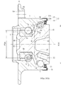
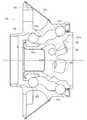
- FIG. 1 is a longitudinal sectional view showing a first embodiment of a wheel bearing device according to the present invention
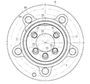
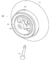
- FIG. 2 is a side view of FIG. 1
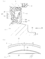
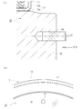
- FIG. 3 (a) is a main part showing positioning means of FIG. (B) is an arrow view seen from the III direction of (a)
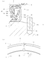
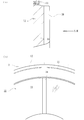
- FIG. 4 (a) is an enlarged view of a main part showing a modification of FIG. 3
- (b) is an IV of (a).
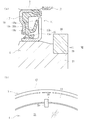
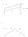
- FIG. 5A is an enlarged view of a main part showing another modified example of FIG. 3
- FIG. 5B is an arrow view seen from the V direction of FIG. a) is an enlarged view of a main part showing another modified example of FIG.
- FIG. 7 (a) is another modified example of FIG. (B) is an arrow view seen from the VII direction of (a).
- the side closer to the outer side of the vehicle when assembled to the vehicle is referred to as the outer side (left side in FIG. 1), and the side closer to the center is referred to as the inner side (right side in FIG. 1).
- This wheel bearing device is for a driven wheel called the third generation, and is an inner member 1 serving as a stationary member, an outer member 2 serving as a rotating member, and a rolling member between both members 1 and 2. It has double row rolling elements (balls) 3 and 3 which are accommodated freely.
- the inner member 1 includes a hub ring 4 and an inner ring 5 press-fitted into the hub ring 4 through a predetermined shimiro.
- the hub wheel 4 is formed with one (inner side) inner rolling surface 4a and a small-diameter stepped portion 4b extending in the axial direction from the inner rolling surface 4a via a stepped portion 7a.
- the inner ring 5 is formed with the other (outer side) inner raceway surface 5a on the outer periphery and is press-fitted into the small-diameter stepped portion 4b of the hub wheel 4 to form a back-to-back type double row angular contact ball bearing.
- the inner ring 5 is fixed in the axial direction by a caulking portion 8 formed by plastic deformation of the end portion of 4b.
- the inner ring 5 and the rolling element 3 are made of high carbon chrome steel such as SUJ2, and are hardened in the range of 58 to 64 HRC up to the core portion by quenching.
- the hub wheel 4 is made of medium and high carbon steel containing 0.40 to 0.80 wt% of carbon such as S53C, and has a surface hardness of 58 by induction hardening from the inner rolling surface 4a to the outer peripheral surface of the small diameter step portion 4b. Hardened to a range of ⁇ 64 HRC.
- the caulking portion 8 is kept in the surface hardness after forging. As a result, the fretting resistance of the small-diameter stepped portion 4b serving as the fitting portion of the inner ring 5 is improved, and the plastic working of the crimped portion 8 can be performed smoothly without occurrence of minute cracks.
- the outer member 2 integrally has a wheel mounting flange 6 for mounting a wheel (not shown) at an end on the outer side, and a bolt hole 6a into which a hub bolt (not shown) is screwed and fixed by a screw.
- a thick rib 6b is formed around the bolt hole 6a. The rib 6b can reduce the weight and the rigidity of the outer member 2, and can secure sufficient strength even when a large bending moment load is applied to the wheel mounting flange 6.
- An inner side outer rolling surface 2b facing the inner rolling surface 4a is integrally formed. Double-row rolling elements 3 and 3 are accommodated between these rolling surfaces and are held by the cages 9 and 10 so as to roll freely.
- This outer member 2 is made of medium and high carbon steel containing 0.40 to 0.80 wt% of carbon such as S53C, and at least the double row outer rolling surfaces 2a and 2b have a surface hardness of 58 to 64 HRC by induction hardening. Hardened to range.
- a seal 11 which will be described later is attached to the opening on the inner side of the annular space formed between the outer member 2 and the inner member 1, and leakage of grease sealed inside the bearing to the outside and from the outside Rain water and dust are prevented from entering the bearing.
- a pulsar ring 12 is attached to the inner side end of the outer member 2.
- the pulsar ring 12 includes a cored bar 13 and a magnetic encoder 14 that is integrally joined to the cored bar 13 by vulcanization adhesion.
- the core 13 is made of a ferromagnetic steel plate, for example, a ferritic stainless steel plate (JIS standard SUS430 or the like), or a rust-proof cold-rolled steel plate, and the cross-section is substantially L-shaped by pressing.
- a cylindrical fitting portion 13a that is formed and press-fitted into the outer periphery of the end portion of the outer member 2, and extends radially inward from the fitting portion 13a and is in close contact with the inner end surface 2c of the outer member 2.
- a flange 13b that increases positioning accuracy.
- the magnetic encoder 14 is a rotary encoder for detecting the rotational speed of a wheel by mixing magnetic powder such as ferrite in an elastomer such as rubber and alternately magnetizing magnetic poles N and S in the circumferential direction.
- magnetic powder such as ferrite in an elastomer such as rubber
- alternately magnetizing magnetic poles N and S in the circumferential direction.
- double row angular contact ball bearing which used the ball for the rolling element 3 was illustrated here, not only this but the double row tapered roller bearing which uses the tapered roller for the rolling element 3 may be sufficient.
- the seal 11 is constituted by a so-called pack seal composed of a slinger 15 and an annular seal plate 16 arranged to face each other as shown in an enlarged view in FIG.
- the slinger 15 is a steel plate having rust prevention capability, for example, an austenitic stainless steel plate (JIS standard SUS304 type or the like), a ferritic stainless steel plate (JIS standard SUS430 type or the like), or a rust-proof cold rolled steel.
- a cross section is formed in a substantially L shape by pressing from a steel plate, and includes a cylindrical portion 15a that is press-fitted into the outer diameter of the hub wheel 4, and a standing plate portion 15b that extends radially outward from the cylindrical portion 15a.
- the seal plate 16 includes a cored bar 17 fitted into the inner end of the outer member 2 and a seal member 18 integrally joined to the cored bar 17 by vulcanization adhesion.
- the metal core 17 has a substantially L-shaped cross section formed by press working from an austenitic stainless steel plate or a cold-rolled steel plate that has been rust-proofed.
- the seal member 18 is made of a synthetic rubber such as NBR (acrylonitrile-butadiene rubber), and extends in a radially outward direction.
- the seal member 18 slides on the outer side surface of the standing plate portion 15b of the slinger 15 via a predetermined axial shimiro. It has a side lip 18a in contact with it, a duster lip 18c and a grease lip 18c that extend in a forked manner on the inner diameter side and slidably contact the cylindrical portion 15a of the slinger 15 via a predetermined radial shimiro.
- HNBR hydrogenated acrylonitrile butadiene rubber
- EPDM ethylene propylene rubber
- ACM polyacrylic rubber
- FKM fluororubber
- silicon rubber which are excellent in the above.
- the pitch circle diameter PCDo of the outer rolling element 3 is set to be smaller than the pitch circle diameter PCDi of the inner rolling element 3 (PCDo ⁇ PCDi).
- the sizes of the double-row rolling elements 3 and 3 are the same, but due to the difference in the pitch circle diameters PCDo and PCDi, the number of the inner-side rolling elements 3 is set larger than the number of the outer-side rolling elements 3. Has been.
- the outer shape of the hub wheel 4 includes a counter portion 19 from the groove bottom portion of the inner rolling surface 4a, a step portion 7a formed to be inclined from the counter portion 19, and a shoulder portion 4c with which the inner ring 5 is abutted. It continues to the small diameter step 4b.
- the outer member 2 is formed such that the outer rolling surface 2a on the outer side has a smaller diameter than the outer rolling surface 2b on the inner side due to the difference in pitch circle diameters PCDo and PCDi.
- An inner side outer rolling surface 2b is formed via a step 7b inclined from the running surface 2a.
- the inclination angle of the step portion 7 b is set to be substantially the same as the inclination angle of the step portion 7 a of the hub wheel 4.
- the pitch circle diameter PCDo of the outer side rolling element 3 is set to be smaller than the pitch circle diameter PCDi of the inner side rolling element 3, and accordingly, the number of rolling elements 3 is also set on the inner side. Since the number of bearings is set to be larger than the number on the outer side, the bearing space can be effectively utilized to increase the bearing rigidity of the inner side portion compared to the outer side, thereby extending the life of the bearing. it can. Furthermore, since the inclination of the step portion 7a of the hub wheel 4 and the step portion 7b of the outer member 2 are set to substantially the same angle, it is possible to solve the conflicting problems of lightening, compactness and high rigidity of the device. it can.
- an attachment portion 21 having a mortar-shaped recess 20 is formed at the inner end of the hub wheel 4.
- the depth of the recess 20 is up to the vicinity of the shoulder 4c, and the mounting portion 21 of the hub wheel 4 has a substantially uniform thickness.
- weight reduction can be achieved, maintaining the intensity
- FIG. 1 a plurality of bolt holes 22 are formed in the mounting portion 21 and are attached to a knuckle (not shown) constituting the suspension device by a fixing bolt (not shown) fastened to the bolt holes 22.
- the positioning means 23 with a knuckle is formed in the outer periphery of the edge part of the attachment part 21 of the hub ring 4. As shown in FIG.
- the positioning means 23 is composed of a flat portion formed by partially cutting the outer periphery of the end portion of the mounting portion 21 of the hub wheel 4. As shown in FIG. And at least one plane part is formed also in the inner circumference of the other party knuckle, and by positioning these plane parts, the positioning in the circumferential direction of the hub wheel 4 and the knuckle can be easily performed. It is possible to provide a wheel bearing device that reduces the number of assembly steps for a vehicle.
- FIG. 4 shows a modification of the positioning means 23 described above.
- An annular groove 25 is formed on the outer periphery of the end portion of the attachment portion 21 of the hub wheel 4, and the positioning means 24 is constituted by a convex portion that protrudes from the bottom of the annular groove 25.
- at least one recessed part is formed also in the inner periphery of the other party knuckle, and the circumferential positioning of the hub wheel 4 and the knuckle can be easily performed by fitting these unevenness
- FIG. 5 shows another modification of the positioning means 23 described above.
- a perforation 26 is formed on the outer periphery of the end of the attachment portion 21 of the hub wheel 4, and the positioning means 27 is configured by a pin press-fitted into the perforation 26 so that the head protrudes.
- at least one recessed part is formed also in the inner periphery of the other party knuckle, and the circumferential positioning of the hub wheel 4 and a knuckle can be performed easily by engaging a pin with this recessed part.
- FIG. 6 shows another modification of the positioning means 23 described above.
- the positioning means 28 is constituted by a recess formed on the outer periphery of the end portion of the attachment portion 21 of the hub wheel 4. And at least 1 convex part is formed also in the inner periphery of the other party knuckle, and the positioning of the hub ring 4 and the knuckle in the circumferential direction can be performed easily by fitting this unevenness
- FIG. 7 shows another modification of the positioning means 23 described above.
- a concave portion 29 is formed on the outer periphery of the end portion of the mounting portion 21 of the hub wheel 4, and the positioning means 30 is constituted by a key member fitted into the concave portion 29.
- at least one key groove is also formed on the inner periphery of the partner knuckle, and the key member can be engaged with the key groove, thereby easily positioning the hub wheel 4 and the knuckle in the circumferential direction. it can.
- FIG. 8 is a longitudinal sectional view showing a second embodiment of the wheel bearing device according to the present invention
- FIG. 9 is a side view of FIG. 8
- FIG. 10 (a) is a main part showing the positioning means of FIG. Enlarged view
- (b) is an arrow view seen from the X direction of (a)
- FIG. 11 (a) is an enlarged view of a main part showing a modification of FIG. 10
- (b) is an XI of (a).
- FIG. 12A is an enlarged view of a main part showing another modified example of FIG. 10
- FIG. 12B is an arrow view seen from the XII direction of FIG. a) is an enlarged view of a main part showing another modification of FIG.
- FIG. 10 is an arrow view seen from the XIII direction of (a)
- FIG. 14 is another modification of FIG. (B) is an arrow view seen from the XIV direction of (a).
- the second embodiment is basically the same as the above-described first embodiment (FIG. 1) except that the positioning means is different, and the same parts or parts having the same function or the same function. Reference numerals are assigned and detailed description is omitted.
- the wheel bearing device includes an inner member 31, an outer member 2, and double-row rolling elements 3, 3 accommodated between the members 31, 2 so as to be freely rollable.
- the inner member 31 includes a hub ring 32 and an inner ring 5 that is press-fitted into the hub ring 32 via a predetermined shimiro.
- the hub wheel 32 is formed with one (inner side) inner rolling surface 4a and a small-diameter stepped portion 4b extending in the axial direction from the inner rolling surface 4a via the stepped portion 7a.
- the hub ring 32 is formed of medium and high carbon steel containing 0.40 to 0.80 wt% of carbon such as S53C, and the surface hardness is increased by induction hardening from the inner rolling surface 4a to the outer peripheral surface of the small diameter step portion 4b. Cured in the range of 58 to 64 HRC.
- a mounting portion 33 having a mortar-shaped recess 20 is formed at the inner end of the hub wheel 32.
- the depth of the recess 20 is up to the vicinity of the shoulder 4c, and the mounting portion 33 of the hub wheel 32 has a substantially uniform thickness.
- a knuckle positioning means 34 is formed on the inner side end face of the mounting portion 33 of the hub wheel 32.
- the positioning means 34 is constituted by a convex portion that is formed to project from the end face of the mounting portion 33 of the hub wheel 32. As shown in FIG. At least one recess is formed on the end surface of the mating knuckle. By fitting these recesses and protrusions, the hub wheel 32 and the knuckle can be easily positioned in the circumferential direction, and assembled into the vehicle. Man-hours can be reduced.
- FIG. 11 shows a modification of the positioning means 34 described above.
- the positioning means 35 is constituted by a perforation formed on the end surface of the attachment portion 33 of the hub wheel 32. And at least one convex part is formed also in the inner periphery of the other side knuckle, and the positioning of the circumferential direction of the hub wheel 32 and a knuckle can be performed easily by fitting these unevenness
- FIG. 12 shows another modification of the positioning means 34 described above.
- a perforation 36 is formed on the end surface of the mounting portion 33 of the hub wheel 32, and the positioning means 37 is configured by a pin press-fitted into the perforation 36.
- at least one recessed part is formed also in the inner periphery of the other party knuckle, and the positioning of the circumferential direction of the hub wheel 32 and a knuckle can be performed easily by fitting these unevenness
- FIG. 13 shows another modification of the positioning means 34 described above.
- the positioning means 38 is configured by a radial groove formed on the end surface of the mounting portion 33 of the hub wheel 32. And at least one convex part is formed also in the inner periphery of the other party knuckle, and the hub ring 32 and the knuckle are easily positioned in the circumferential direction by being engaged with the positioning means 38 formed of the radiation groove. This can reduce the number of assembly steps for the vehicle.
- FIG. 14 shows another modification of the positioning means 34 described above.
- a radial groove 39 is formed on the end surface of the mounting portion 33 of the hub wheel 32, and the positioning means 40 is composed of a key member fixed to the radial groove 39.
- at least one key groove is also formed on the inner periphery of the knuckle on the other side, and by fitting these irregularities, the circumferential positioning of the hub wheel 32 and the knuckle can be easily performed, and the vehicle The number of assembly steps can be reduced.
- FIG. 15 is a longitudinal sectional view showing a third embodiment of the wheel bearing device according to the present invention
- FIG. 16 is a side view of FIG. 15
- FIG. 17 (a) is a main part showing the positioning means of FIG. Enlarged view
- (b) is an arrow view seen from the XVII direction of (a)
- FIG. 18 (a) is an enlarged view of a main part showing a modification of FIG. 17,
- (b) is an XVIII of (a). It is an arrow view seen from the direction.
- the third embodiment is basically the same as the above-described first embodiment (FIG. 1) except that the positioning means is different, and the same parts or parts having the same function or the same function. Reference numerals are assigned and detailed description is omitted.
- This wheel bearing device includes an inner member 41, an outer member 2, and double row rolling elements 3, 3 accommodated between both members 41, 2 so as to freely roll.
- the inner member 41 includes a hub ring 42 and an inner ring 5 that is press-fitted into the hub ring 42 through a predetermined shimiro.
- the hub wheel 42 is formed with one (inner side) inner rolling surface 4a and a small-diameter stepped portion 4b extending in the axial direction from the inner rolling surface 4a via the stepped portion 7a.
- the hub wheel 42 is made of medium and high carbon steel containing 0.40 to 0.80 wt% of carbon such as S53C, and the surface hardness is increased by induction hardening from the inner rolling surface 4a to the outer peripheral surface of the small diameter step portion 4b. Cured in the range of 58 to 64 HRC.
- a mounting portion 43 having a mortar-shaped recess 20 is formed at the end on the inner side of the hub wheel 42.
- the depth of the recess 20 is up to the vicinity of the shoulder 4c, and the mounting portion 43 of the hub wheel 42 has a substantially uniform thickness.
- a knuckle positioning means 44 is formed on the inner diameter surface of the mounting portion 43 of the hub wheel 42.
- the positioning means 44 is constituted by a convex portion formed so as to protrude from the inner diameter surface of the mounting portion 43 of the hub wheel 42. As shown in FIG. Then, at least one recess is formed in the mating knuckle. By fitting these irregularities, the circumferential positioning of the hub wheel 42 and the knuckle can be easily performed, and the assembly man-hour for the vehicle can be reduced. Reduction can be achieved.
- FIG. 18 shows a modification of the positioning means 44 described above.
- the positioning means 45 is constituted by a recess formed on the inner diameter surface of the mounting portion 43 of the hub wheel 42. And at least one convex part is formed in the other side knuckle, and the positioning of the circumferential direction of the hub wheel 42 and the knuckle can be easily performed by fitting these unevenness
- the wheel bearing device according to the present invention can be applied to a third-generation outer ring rotation type wheel bearing device.
Landscapes
- Engineering & Computer Science (AREA)
- General Engineering & Computer Science (AREA)
- Mechanical Engineering (AREA)
- Rolling Contact Bearings (AREA)
- Sealing With Elastic Sealing Lips (AREA)
- Mounting Of Bearings Or Others (AREA)
- Sealing Of Bearings (AREA)
Abstract
【課題】内方部材に位置決め手段を設け、車両への組立工数の削減を図った車輪用軸受装置を提供する。 【解決手段】複列の転動体3のうちインナー側の転動体3のピッチ円直径PCDiがアウター側の転動体3のピッチ円直径PCDoよりも大径に設定された外輪回転タイプの第3世代構造の車輪用軸受装置において、ハブ輪4のインナー側の端部に凹所20を有する略均一な肉厚の取付部21が形成され、この取付部21にボルト孔22が複数個形成されてハブ輪4と懸架装置が固定ボルトを介して締結されると共に、当該ハブ輪4の取付部21に懸架装置と周方向の位置決めを行うための位置決め手段23が形成され、この位置決め手段23が取付部21の端部外周を一部カットして形成された平面部で構成されている。
Description
本発明は、自動車等の車輪を回転自在に支承する車輪用軸受装置、特に、外方部材が車輪と共に回転する、所謂外輪回転タイプに関し、内方部材に位置決め手段を設け、車両への組立工数の削減を図った車輪用軸受装置に関するものである。
従来から自動車等の車輪を支持する車輪用軸受装置は、車輪を取り付けるためのハブ輪を転がり軸受を介して回転自在に支承するもので、駆動輪用と従動輪用とがある。構造上の理由から、駆動輪用では内輪回転タイプが、従動輪用では内輪回転と外輪回転の両タイプが一般的に採用されているが、外輪回転タイプの車輪用軸受装置は、懸架装置への取付部の構造を内輪回転タイプよりも簡素化できるため、一部の自動車で従動輪支持用の車輪用軸受装置として使用されている。然しながら、内方部材に比べて直径が大きな外方部材を回転させるため、慣性モーメントが大きくなり、加速性能を中心とする走行性能や燃費性能を確保する面から、内輪回転タイプに比べて不利になる。このような不利を低減乃至解消するためには、外方部材の軽量化が効果的である。このような事情に鑑みて考えられた外輪回転タイプの車輪用軸受装置として、従来から図19、図20に示すような構造が知られている。
この車輪用軸受装置100は、内方部材101と、外方部材102と、複列のボール103と、補強部材104とを備えている。このうち内方部材101は、外周面に複列の内側転走面101a、101bが形成され、使用状態で懸架装置に支持固定されて回転しない。一方、外方部材102は、外周面に回転側フランジ105を一体に有し、内周面に複列の外側転走面102a、102bが形成されている。そして、使用状態でこの車輪取付フランジ105に結合固定された車輪(図示せず)と共に回転する。
補強部材104は、全体を部分円すい筒状とし、大径側端部を回転側フランジ105の外周縁部に、同じく小径端部を外方部材102の外周面で、この回転側フランジ105よりも軸方向内方寄り部分に、それぞれ溶接により接合固定している。さらに、内方部材101を懸架装置に対し固定するために、この内方部材101の内周面に静止側フランジ106が形成されている。
ここで、旋回走行時等には、車輪と路面との接触部からの入力が回転側フランジ105に対し、この回転側フランジ105を外方部材102の本体部分に対し曲げる方向のモーメントとして加わる。すなわち、回転側フランジ105と外方部材102の本体部分との間に補強部材104を設けているので、モーメントに拘わらず、回転側フランジ105が外方部材102の本体部分に対し曲がることを抑えられる。このため、外方部材102を薄肉化しても、車輪の支持剛性を確保して、走行安定性等の必要とする性能を確保することができる(例えば、特許文献1参照。)。
こうした車輪用軸受装置100において、内方部材101の静止側フランジ106に固定ボルト107を締結するためのタップ穴108が設けてあり、懸架装置側から固定ボルト107を組み付ける際、懸架装置と内方部材101との周方向位置決めが難しいという問題があった。
本発明は、このような事情に鑑みてなされたもので、内方部材に位置決め手段を設け、車両への組立工数の削減を図った車輪用軸受装置を提供することを目的としている。
係る目的を達成すべく、本発明のうち請求項1記載の発明は、外周に車輪を取り付けるための車輪取付フランジを一体に有し、内周に複列の外側転走面が一体に形成された外方部材と、外周に前記複列の外側転走面に対向する一方の内側転走面と、この内側転走面から傾斜する段部を介して軸方向に延びる小径段部が形成されたハブ輪、およびこのハブ輪の小径段部に圧入され、外周に前記複列の外側転走面に対向する他方の内側転走面が形成されて背面合せタイプの複列アンギュラ玉軸受を構成する内輪からなる内方部材と、この内方部材と前記外方部材の両転走面間に転動自在に収容された複列の転動体とを備え、前記小径段部の端部を径方向外方に塑性変形させて形成した加締部によって前記内輪が軸方向に固定されると共に、前記複列の転動体のうちインナー側の転動体のピッチ円直径がアウター側の転動体のピッチ円直径よりも大径に設定された車輪用軸受装置において、前記ハブ輪のインナー側の端部に凹所を有する略均一な肉厚の取付部が形成され、この取付部にボルト孔が複数個形成されて前記ハブ輪と懸架装置が固定ボルトを介して締結されると共に、当該ハブ輪の取付部の端部に前記懸架装置と周方向の位置決めを行うための位置決め手段が形成されている。
このように、複列の転動体のうちインナー側の転動体のピッチ円直径がアウター側の転動体のピッチ円直径よりも大径に設定された外輪回転タイプの第3世代構造の車輪用軸受装置において、ハブ輪のインナー側の端部に凹所を有する略均一な肉厚の取付部が形成され、この取付部にボルト孔が複数個形成されてハブ輪と懸架装置が固定ボルトを介して締結されると共に、当該ハブ輪の取付部の端部に懸架装置と周方向の位置決めを行うための位置決め手段が形成されているので、ハブ輪と懸架装置との周方向の位置決めを容易に行うことができ、車両への組立工数の削減を図った車輪用軸受装置を提供することができる。
また、請求項2に記載の発明のように、前記位置決め手段が前記取付部の端部外周に設けられていても良い。
また、請求項3に記載の発明のように、前記位置決め手段が前記取付部の端面に設けられていても良い。
また、請求項4に記載の発明のように、前記位置決め手段が前記取付部の端部内周に設けられていても良い。
また、請求項5に記載の発明のように、前記ハブ輪の位置決め手段に対応して前記懸架装置に少なくとも一つの係合手段が形成されていれば、ハブ輪と懸架装置との周方向の位置決めを容易に行うことができる。
また、請求項6に記載の発明のように、前記取付部の凹所の深さが、前記内輪が突き合わされる肩部付近までとされていれば、ハブ輪の強度を保ちつつ軽量化を図ることができる。
また、請求項7に記載の発明のように、前記外方部材が、前記ピッチ円直径の違いに伴い、前記複列の外側転走面のうちアウター側の外側転走面がインナー側の外側転走面よりも縮径して形成され、当該アウター側の外側転走面から傾斜した段部を介して前記インナー側の外側転走面が形成されると共に、前記段部の傾斜角が前記ハブ輪の段部の傾斜角と略同一角度になるように設定されていれば、装置の軽量・コンパクト化と高剛性化という相反する課題を解決することができる。
また、請求項8に記載の発明のように、前記複列の転動体のうちインナー側の転動体の個数がアウター側の個数よりも多く設定されていれば、有効に軸受スペースを活用してアウター側に比べインナー側部分の軸受剛性を増大させることができ、軸受の長寿命化を図ることができる。
また、請求項9に記載の発明のように、前記車輪取付フランジにハブボルトが圧入固定されるボルト孔が穿設され、このボルト孔の周辺に肉厚のリブが形成されていれば、外方部材の軽量化と高剛性化を図ることができ、大きな曲げモーメント荷重がこの車輪取付フランジに負荷されても充分な強度を確保することができる。
また、請求項10に記載の発明のように、前記ハブ輪の内側転走面から小径段部の外周面に亙って高周波焼入れによって表面硬さを58~64HRCの範囲に硬化処理され、前記加締部が鍛造加工後の表面硬さのままとされていれば、内輪の嵌合部となる小径段部の耐フレッティング性が向上すると共に、微小なクラック等の発生がなく加締部の塑性加工をスムーズに行うことができる。
本発明に係る車輪用軸受装置は、外周に車輪を取り付けるための車輪取付フランジを一体に有し、内周に複列の外側転走面が一体に形成された外方部材と、外周に前記複列の外側転走面に対向する一方の内側転走面と、この内側転走面から傾斜する段部を介して軸方向に延びる小径段部が形成されたハブ輪、およびこのハブ輪の小径段部に圧入され、外周に前記複列の外側転走面に対向する他方の内側転走面が形成されて背面合せタイプの複列アンギュラ玉軸受を構成する内輪からなる内方部材と、この内方部材と前記外方部材の両転走面間に転動自在に収容された複列の転動体とを備え、前記小径段部の端部を径方向外方に塑性変形させて形成した加締部によって前記内輪が軸方向に固定されると共に、前記複列の転動体のうちインナー側の転動体のピッチ円直径がアウター側の転動体のピッチ円直径よりも大径に設定された車輪用軸受装置において、前記ハブ輪のインナー側の端部に凹所を有する略均一な肉厚の取付部が形成され、この取付部にボルト孔が複数個形成されて前記ハブ輪と懸架装置が固定ボルトを介して締結されると共に、当該ハブ輪の取付部の端部に前記懸架装置と周方向の位置決めを行うための位置決め手段が形成されているので、ハブ輪と懸架装置との周方向の位置決めを容易に行うことができ、車両への組立工数の削減を図った車輪用軸受装置を提供することができる。
外周に車輪を取り付けるための車輪取付フランジを一体に有し、内周に複列の外側転走面が一体に形成された外方部材と、外周に前記複列の外側転走面に対向する一方の内側転走面と、この内側転走面から傾斜する段部を介して軸方向に延びる小径段部が形成されたハブ輪、およびこのハブ輪の小径段部に圧入され、外周に前記複列の外側転走面に対向する他方の内側転走面が形成されて背面合せタイプの複列アンギュラ玉軸受を構成する内輪からなる内方部材と、この内方部材と前記外方部材の両転走面間に転動自在に収容された複列の転動体とを備え、前記小径段部の端部を径方向外方に塑性変形させて形成した加締部によって前記内輪が軸方向に固定されると共に、前記複列の転動体のうちインナー側の転動体のピッチ円直径がアウター側の転動体のピッチ円直径よりも大径に設定された車輪用軸受装置において、前記ハブ輪のインナー側の端部に凹所を有する略均一な肉厚の取付部が形成され、この取付部にボルト孔が複数個形成されて前記ハブ輪と懸架装置が固定ボルトを介して締結されると共に、当該ハブ輪の取付部に前記懸架装置と周方向の位置決めを行うための位置決め手段が形成され、この位置決め手段が前記取付部の端部外周を一部カットして形成された平面部で構成されている。
以下、本発明の実施の形態を図面に基づいて詳細に説明する。
図1は、本発明に係る車輪用軸受装置の第1の実施形態を示す縦断面図、図2は、図1の側面図、図3(a)は、図1の位置決め手段を示す要部拡大図、(b)は、(a)のIII方向から見た矢視図、図4(a)は、図3の変形例を示す要部拡大図、(b)は、(a)のIV方向から見た矢視図、図5(a)は、図3の他の変形例を示す要部拡大図、(b)は、(a)のV方向から見た矢視図、図6(a)は、図3の他の変形例を示す要部拡大図、(b)は、(a)のVI方向から見た矢視図、図7(a)は、図3の他の変形例を示す要部拡大図、(b)は、(a)のVII方向から見た矢視図である。なお、以下の説明では、車両に組み付けた状態で車両の外側寄りとなる側をアウター側(図1の左側)、中央寄り側をインナー側(図1の右側)という。
図1は、本発明に係る車輪用軸受装置の第1の実施形態を示す縦断面図、図2は、図1の側面図、図3(a)は、図1の位置決め手段を示す要部拡大図、(b)は、(a)のIII方向から見た矢視図、図4(a)は、図3の変形例を示す要部拡大図、(b)は、(a)のIV方向から見た矢視図、図5(a)は、図3の他の変形例を示す要部拡大図、(b)は、(a)のV方向から見た矢視図、図6(a)は、図3の他の変形例を示す要部拡大図、(b)は、(a)のVI方向から見た矢視図、図7(a)は、図3の他の変形例を示す要部拡大図、(b)は、(a)のVII方向から見た矢視図である。なお、以下の説明では、車両に組み付けた状態で車両の外側寄りとなる側をアウター側(図1の左側)、中央寄り側をインナー側(図1の右側)という。
この車輪用軸受装置は第3世代と呼称される従動輪用であって、固定側部材となる内方部材1と、回転側部材となる外方部材2、および両部材1、2間に転動自在に収容された複列の転動体(ボール)3、3とを備えている。内方部材1は、ハブ輪4と、このハブ輪4に所定のシメシロを介して圧入された内輪5とからなる。
ハブ輪4は、外周に一方(インナー側)の内側転走面4aと、この内側転走面4aから段部7aを介して軸方向に延びる小径段部4bが形成されている。内輪5は、外周に他方(アウター側)の内側転走面5aが形成され、ハブ輪4の小径段部4bに圧入されて背面合せタイプの複列アンギュラ玉軸受を構成すると共に、小径段部4bの端部を塑性変形させて形成した加締部8によって内輪5が軸方向に固定されている。なお、内輪5および転動体3はSUJ2等の高炭素クロム鋼で形成され、ズブ焼入れによって芯部まで58~64HRCの範囲に硬化処理されている。
ハブ輪4はS53C等の炭素0.40~0.80wt%を含む中高炭素鋼で形成され、内側転走面4aから小径段部4bの外周面に亙って高周波焼入れによって表面硬さを58~64HRCの範囲に硬化処理されている。なお、加締部8は鍛造加工後の表面硬さのままとされている。これにより、内輪5の嵌合部となる小径段部4bの耐フレッティング性が向上すると共に、微小なクラック等の発生がなく加締部8の塑性加工をスムーズに行うことができる。
外方部材2は、アウター側の端部に車輪(図示せず)を取り付けるための車輪取付フランジ6を一体に有し、ハブボルト(図示せず)がねじにより螺合固定されるボルト孔6aが穿設され、このボルト孔6aの周辺は肉厚のリブ6bが形成されている。このリブ6bにより、外方部材2の軽量化と高剛性化を図ることができ、大きな曲げモーメント荷重がこの車輪取付フランジ6に負荷されても充分な強度を確保することができる。
また、外方部材2の内周には、内輪5の内側転走面5aに対向するアウター側の外側転走面2aと、この外側転走面2aから段部7bを介してハブ輪4の内側転走面4aに対向するインナー側の外側転走面2bが一体に形成されている。これら両転走面間に複列の転動体3、3が収容され、保持器9、10によって転動自在に保持されている。この外方部材2はS53C等の炭素0.40~0.80wt%を含む中高炭素鋼で形成され、少なくとも複列の外側転走面2a、2bが高周波焼入れによって表面硬さを58~64HRCの範囲に硬化処理されている。
外方部材2と内方部材1との間に形成される環状空間のインナー側の開口部には後述するシール11が装着され、軸受内部に封入されたグリースの外部への漏洩と、外部から雨水やダスト等が軸受内部に侵入するのを防止している。また、外方部材2のインナー側の端部にパルサーリング12が装着されている。このパルサーリング12は、芯金13と、この芯金13に加硫接着によって一体に接合される磁気エンコーダ14とからなる。
芯金13は、強磁性体の鋼板、例えば、フェライト系のステンレス鋼板(JIS規格のSUS430系等)、あるいは、防錆処理された冷間圧延鋼板からプレス加工にて断面が略L字状に形成され、外方部材2の端部外周に圧入される円筒状の嵌合部13aと、この嵌合部13aから径方向内方に延び、外方部材2のインナー側の端面2cに密着して位置決め精度を高める鍔部13bとを備えている。磁気エンコーダ14は、ゴム等のエラストマにフェライト等の磁性体粉が混入されると共に、周方向に交互に磁極N、Sが着磁され、車輪の回転速度検出用のロータリエンコーダを構成している。なお、ここでは、転動体3にボールを使用した複列アンギュラ玉軸受を例示したが、これに限らず、転動体3に円錐ころを使用した複列円錐ころ軸受であっても良い。
シール11は、図3(a)に拡大して示すように、互いに対向配置されたスリンガ15と環状のシール板16とからなる、所謂パックシールで構成されている。スリンガ15は、防錆能を有する鋼板、例えば、オーステナイト系ステンレス鋼板(JIS規格のSUS304系等)やフェライト系のステンレス鋼板(JIS規格のSUS430系等)、あるいは、防錆処理された冷間圧延鋼板からプレス加工にて断面が略L字状に形成され、ハブ輪4の外径に圧入される円筒部15aと、この円筒部15aから径方向外方に延びる立板部15bとからなる。
一方、シール板16は、外方部材2のインナー側の端部に内嵌される芯金17と、この芯金17に加硫接着により一体に接合されたシール部材18とからなる。芯金17は、オーステナイト系ステンレス鋼板、あるいは、防錆処理された冷間圧延鋼板からプレス加工にて断面が略L字状に形成されている。
シール部材18はNBR(アクリロニトリル-ブタジエンゴム)等の合成ゴムからなり、径方向外方に傾斜して延び、スリンガ15の立板部15bのアウター側の側面に所定の軸方向シメシロを介して摺接するサイドリップ18aと、この内径側で二股状に傾斜して延び、スリンガ15の円筒部15aに所定の径方向シメシロを介して摺接するダストリップ18bとグリースリップ18cを有している。なお、シール部材18の材質としては、例示したNBR以外にも、例えば、耐熱性に優れたHNBR(水素化アクリロニトリル・ブタジエンゴム)、EPDM(エチレンプロピレンゴム)等をはじめ、耐熱性、耐薬品性に優れたACM(ポリアクリルゴム)、FKM(フッ素ゴム)、あるいはシリコンゴム等を例示することができる。
本実施形態では、図1に示すように、アウター側の転動体3のピッチ円直径PCDoがインナー側の転動体3のピッチ円直径PCDiよりも小径に設定されている(PCDo<PCDi)。そして、複列の転動体3、3のサイズは同じであるが、このピッチ円直径PCDo、PCDiの違いにより、インナー側の転動体3の個数がアウター側の転動体3の個数よりも多く設定されている。
ハブ輪4の外郭形状は、内側転走面4aの溝底部からカウンタ部19と、このカウンタ部19から傾斜して形成された段部7a、および内輪5が突き合わされる肩部4cを介して小径段部4bに続いている。一方、外方部材2において、ピッチ円直径PCDo、PCDiの違いに伴い、アウター側の外側転走面2aがインナー側の外側転走面2bよりも縮径して形成され、アウター側の外側転走面2aから傾斜した段部7bを介してインナー側の外側転走面2bが形成されている。この段部7bの傾斜角は、ハブ輪4の段部7aの傾斜角と略同一角度になるように設定されている。
こうした構成の車輪用軸受装置では、アウター側の転動体3のピッチ円直径PCDoをインナー側の転動体3のピッチ円直径PCDiよりも小径に設定され、その分、転動体3の個数もインナー側の個数がアウター側の個数よりも多く設定されているため、有効に軸受スペースを活用してアウター側に比べインナー側部分の軸受剛性を増大させることができ、軸受の長寿命化を図ることができる。さらに、ハブ輪4の段部7aと外方部材2の段部7bの傾斜が略同一角度に設定されているので、装置の軽量・コンパクト化と高剛性化という相反する課題を解決することができる。
ここで、ハブ輪4のインナー側の端部にはすり鉢状の凹所20を有する取付部21が形成されている。この凹所20の深さは肩部4c付近までとされ、ハブ輪4の取付部21が略均一な肉厚となっている。これにより、ハブ輪4の強度を保ちつつ軽量化を図ることができる。本実施形態では、この取付部21にボルト孔22が複数個形成され、これらボルト孔22に締結される固定ボルト(図示せず)によって懸架装置を構成するナックル(図示せず)に取り付けられる。そして、ハブ輪4の取付部21の端部外周にナックルとの位置決め手段23が形成されている。
この位置決め手段23は、図2および図3に示すように、ハブ輪4の取付部21の端部外周を一部カットして形成された平面部で構成されている。そして、相手側のナックルの内周にも少なくとも一つの平面部が形成され、これら平面部同士を嵌合させることにより、ハブ輪4とナックルとの周方向の位置決めを容易に行うことができ、車両への組立工数の削減を図った車輪用軸受装置を提供することができる。
図4に前述した位置決め手段23の変形例を示す。ハブ輪4の取付部21の端部外周に環状溝25が形成されると共に、位置決め手段24は、この環状溝25の底部に突出して形成された凸部で構成されている。そして、相手側のナックルの内周にも少なくとも一つの凹部が形成され、これら凹凸を嵌合させることにより、ハブ輪4とナックルとの周方向の位置決めを容易に行うことができ、車両への組立工数の削減を図ることができる。
図5に前述した位置決め手段23の他の変形例を示す。ハブ輪4の取付部21の端部外周に穿孔26が形成されると共に、位置決め手段27は、この穿孔26に頭部が突出するように圧入されたピンで構成されている。そして、相手側のナックルの内周にも少なくとも一つの凹部が形成され、この凹部にピンを係合させることにより、ハブ輪4とナックルとの周方向の位置決めを容易に行うことができる。
図6に前述した位置決め手段23の他の変形例を示す。位置決め手段28は、ハブ輪4の取付部21の端部外周に形成された凹部で構成されている。そして、相手側のナックルの内周にも少なくとも一つの凸部が形成され、この凹凸を嵌合させることにより、ハブ輪4とナックルとの周方向の位置決めを容易に行うことができる。
図7に前述した位置決め手段23の他の変形例を示す。ハブ輪4の取付部21の端部外周に凹部29が形成されると共に、位置決め手段30は、この凹部29に嵌着されたキー部材で構成されている。そして、相手側のナックルの内周にも少なくとも一つのキー溝が形成され、このキー溝にキー部材を係合させることにより、ハブ輪4とナックルとの周方向の位置決めを容易に行うことができる。
図8は、本発明に係る車輪用軸受装置の第2の実施形態を示す縦断面図、図9は、図8の側面図、図10(a)は、図8の位置決め手段を示す要部拡大図、(b)は、(a)のX方向から見た矢視図、図11(a)は、図10の変形例を示す要部拡大図、(b)は、(a)のXI方向から見た矢視図、図12(a)は、図10の他の変形例を示す要部拡大図、(b)は、(a)のXII方向から見た矢視図、図13(a)は、図10の他の変形例を示す要部拡大図、(b)は、(a)のXIII方向から見た矢視図、図14(a)は、図10の他の変形例を示す要部拡大図、(b)は、(a)のXIV方向から見た矢視図である。なお、この第2の実施形態は、前述した第1の実施形態(図1)と基本的には位置決め手段が異なるだけで、その他同一部品同一部位あるいは同様の機能を有する部品や部位には同じ符号を付して詳細な説明を省略する。
この車輪用軸受装置は、内方部材31と外方部材2、および両部材31、2間に転動自在に収容された複列の転動体3、3とを備えている。内方部材31は、ハブ輪32と、このハブ輪32に所定のシメシロを介して圧入された内輪5とからなる。
ハブ輪32は、外周に一方(インナー側)の内側転走面4aと、この内側転走面4aから段部7aを介して軸方向に延びる小径段部4bが形成されている。このハブ輪32はS53C等の炭素0.40~0.80wt%を含む中高炭素鋼で形成され、内側転走面4aから小径段部4bの外周面に亙って高周波焼入れによって表面硬さを58~64HRCの範囲に硬化処理されている。
ここで、ハブ輪32のインナー側の端部にはすり鉢状の凹所20を有する取付部33が形成されている。この凹所20の深さは肩部4c付近までとされ、ハブ輪32の取付部33が略均一な肉厚となっている。本実施形態では、ハブ輪32の取付部33のインナー側の端面にナックルとの位置決め手段34が形成されている。
この位置決め手段34は、図9および図10に示すように、ハブ輪32の取付部33の端面に突出して形成された凸部で構成されている。そして、相手側のナックルの端面には少なくとも一つの凹部が形成され、これら凹凸を嵌合させることにより、ハブ輪32とナックルとの周方向の位置決めを容易に行うことができ、車両への組立工数の削減を図ることができる。
図11に前述した位置決め手段34の変形例を示す。この位置決め手段35は、ハブ輪32の取付部33の端面に形成された穿孔で構成されている。そして、相手側のナックルの内周にも少なくとも一つの凸部が形成され、これら凹凸を嵌合させることにより、ハブ輪32とナックルとの周方向の位置決めを容易に行うことができ、車両への組立工数の削減を図ることができる。
図12に前述した位置決め手段34の他の変形例を示す。ハブ輪32の取付部33の端面に穿孔36が形成されると共に、位置決め手段37は、穿孔36に圧入されたピンで構成されている。そして、相手側のナックルの内周にも少なくとも一つの凹部が形成され、これら凹凸を嵌合させることにより、ハブ輪32とナックルとの周方向の位置決めを容易に行うことができ、車両への組立工数の削減を図ることができる。
図13に前述した位置決め手段34の他の変形例を示す。位置決め手段38は、ハブ輪32の取付部33の端面に形成された放射溝で構成されている。そして、相手側のナックルの内周にも少なくとも一つの凸部が形成され、この放射溝からなる位置決め手段38に係合させることにより、ハブ輪32とナックルとの周方向の位置決めを容易に行うことができ、車両への組立工数の削減を図ることができる。
図14に前述した位置決め手段34の他の変形例を示す。ハブ輪32の取付部33の端面に放射溝39が形成されると共に、位置決め手段40は、この放射溝39に固定されたキー部材で構成されている。そして、相手側のナックルの内周にも少なくとも一つのキー溝が形成され、これら凹凸を嵌合させることにより、ハブ輪32とナックルとの周方向の位置決めを容易に行うことができ、車両への組立工数の削減を図ることができる。
図15は、本発明に係る車輪用軸受装置の第3の実施形態を示す縦断面図、図16は、図15の側面図、図17(a)は、図15の位置決め手段を示す要部拡大図、(b)は、(a)のXVII方向から見た矢視図、図18(a)は、図17の変形例を示す要部拡大図、(b)は、(a)のXVIII方向から見た矢視図である。なお、この第3の実施形態は、前述した第1の実施形態(図1)と基本的には位置決め手段が異なるだけで、その他同一部品同一部位あるいは同様の機能を有する部品や部位には同じ符号を付して詳細な説明を省略する。
この車輪用軸受装置は、内方部材41と外方部材2、および両部材41、2間に転動自在に収容された複列の転動体3、3とを備えている。内方部材41は、ハブ輪42と、このハブ輪42に所定のシメシロを介して圧入された内輪5とからなる。
ハブ輪42は、外周に一方(インナー側)の内側転走面4aと、この内側転走面4aから段部7aを介して軸方向に延びる小径段部4bが形成されている。このハブ輪42はS53C等の炭素0.40~0.80wt%を含む中高炭素鋼で形成され、内側転走面4aから小径段部4bの外周面に亙って高周波焼入れによって表面硬さを58~64HRCの範囲に硬化処理されている。
ここで、ハブ輪42のインナー側の端部にはすり鉢状の凹所20を有する取付部43が形成されている。この凹所20の深さは肩部4c付近までとされ、ハブ輪42の取付部43が略均一な肉厚となっている。本実施形態では、ハブ輪42の取付部43の内径面にナックルとの位置決め手段44が形成されている。
この位置決め手段44は、図16および図17に示すように、ハブ輪42の取付部43の内径面に突出して形成された凸部で構成されている。そして、相手側のナックルには少なくとも一つの凹部が形成され、これら凹凸を嵌合させることにより、ハブ輪42とナックルとの周方向の位置決めを容易に行うことができ、車両への組立工数の削減を図ることができる。
図18に前述した位置決め手段44の変形例を示す。この位置決め手段45は、ハブ輪42の取付部43の内径面に形成された凹部で構成されている。そして、相手側のナックルに少なくとも一つの凸部が形成され、これら凹凸を嵌合させることにより、ハブ輪42とナックルとの周方向の位置決めを容易に行うことができ、車両への組立工数の削減を図ることができる。
以上、本発明の実施の形態について説明を行ったが、本発明はこうした実施の形態に何等限定されるものではなく、あくまで例示であって、本発明の要旨を逸脱しない範囲内において、さらに種々なる形態で実施し得ることは勿論のことであり、本発明の範囲は、特許請求の範囲の記載によって示され、さらに特許請求の範囲に記載の均等の意味、および範囲内のすべての変更を含む。
本発明に係る車輪用軸受装置は、第3世代構造の外輪回転タイプの車輪用軸受装置に適用することができる。
1、31、41 内方部材
2 外方部材
2a、2b 外側転走面
2c 外方部材のインナー側の端面
3 転動体
4、32、42 ハブ輪
4a、5a 内側転走面
4b 小径段部
4c 肩部
5 内輪
6 車輪取付フランジ
6a ボルト孔
6b リブ
7a、7b 段部
8 加締部
9、10 保持器
11 シール
12 パルサーリング
13、17 芯金
13a 嵌合部
13b 鍔部
14 磁気エンコーダ
15 スリンガ
15a 円筒部
15b 立板部
16 シール板
18 シール部材
18a サイドリップ
18b ダストリップ
18c グリースリップ
19 カウンタ部
20 凹所
21、33、43 取付部
22 ボルト孔
23、24、27、28、30、34、35、37、38、40、44、45 位置決め手段
25 環状溝
26、36 穿孔
29 凹部
39 放射溝
100 車輪用軸受装置
101 内方部材
101a、101b 内側転走面
102 外方部材
102a、102b 外側転走面
103 ボール
104 補強部材
105 回転側フランジ
106 静止側フランジ
107 固定ボルト
108 タップ穴
PCDi インナー側の転動体のピッチ円直径
PCDo アウター側の転動体のピッチ円直径
2 外方部材
2a、2b 外側転走面
2c 外方部材のインナー側の端面
3 転動体
4、32、42 ハブ輪
4a、5a 内側転走面
4b 小径段部
4c 肩部
5 内輪
6 車輪取付フランジ
6a ボルト孔
6b リブ
7a、7b 段部
8 加締部
9、10 保持器
11 シール
12 パルサーリング
13、17 芯金
13a 嵌合部
13b 鍔部
14 磁気エンコーダ
15 スリンガ
15a 円筒部
15b 立板部
16 シール板
18 シール部材
18a サイドリップ
18b ダストリップ
18c グリースリップ
19 カウンタ部
20 凹所
21、33、43 取付部
22 ボルト孔
23、24、27、28、30、34、35、37、38、40、44、45 位置決め手段
25 環状溝
26、36 穿孔
29 凹部
39 放射溝
100 車輪用軸受装置
101 内方部材
101a、101b 内側転走面
102 外方部材
102a、102b 外側転走面
103 ボール
104 補強部材
105 回転側フランジ
106 静止側フランジ
107 固定ボルト
108 タップ穴
PCDi インナー側の転動体のピッチ円直径
PCDo アウター側の転動体のピッチ円直径
Claims (10)
- 外周に車輪を取り付けるための車輪取付フランジを一体に有し、内周に複列の外側転走面が一体に形成された外方部材と、
外周に前記複列の外側転走面に対向する一方の内側転走面と、この内側転走面から傾斜する段部を介して軸方向に延びる小径段部が形成されたハブ輪、およびこのハブ輪の小径段部に圧入され、外周に前記複列の外側転走面に対向する他方の内側転走面が形成されて背面合せタイプの複列アンギュラ玉軸受を構成する内輪からなる内方部材と、
この内方部材と前記外方部材の両転走面間に転動自在に収容された複列の転動体とを備え、
前記小径段部の端部を径方向外方に塑性変形させて形成した加締部によって前記内輪が軸方向に固定されると共に、
前記複列の転動体のうちインナー側の転動体のピッチ円直径がアウター側の転動体のピッチ円直径よりも大径に設定された車輪用軸受装置において、
前記ハブ輪のインナー側の端部に凹所を有する略均一な肉厚の取付部が形成され、この取付部にボルト孔が複数個形成されて前記ハブ輪と懸架装置が固定ボルトを介して締結されると共に、当該ハブ輪の取付部の端部に前記懸架装置と周方向の位置決めを行うための位置決め手段が形成されていることを特徴とする車輪用軸受装置。 - 前記位置決め手段が前記取付部の端部外周に設けられている請求項1に記載の車輪用軸受装置。
- 前記位置決め手段が前記取付部の端面に設けられている請求項1に記載の車輪用軸受装置。
- 前記位置決め手段が前記取付部の端部内周に設けられている請求項1に記載の車輪用軸受装置。
- 前記ハブ輪の位置決め手段に対応して前記懸架装置に少なくとも一つの係合手段が形成されている請求項1乃至4いずれかに記載の車輪用軸受装置。
- 前記取付部の凹所の深さが、前記内輪が突き合わされる肩部付近までとされている請求項1に記載の車輪用軸受装置。
- 前記外方部材が、前記ピッチ円直径の違いに伴い、前記複列の外側転走面のうちアウター側の外側転走面がインナー側の外側転走面よりも縮径して形成され、当該アウター側の外側転走面から傾斜した段部を介して前記インナー側の外側転走面が形成されると共に、前記段部の傾斜角が前記ハブ輪の段部の傾斜角と略同一角度になるように設定されている請求項1に記載の車輪用軸受装置。
- 前記複列の転動体のうちインナー側の転動体の個数がアウター側の個数よりも多く設定されている請求項1に記載の車輪用軸受装置。
- 前記車輪取付フランジにハブボルトが圧入固定されるボルト孔が穿設され、このボルト孔の周辺に肉厚のリブが形成されている請求項1に記載の車輪用軸受装置。
- 前記ハブ輪の内側転走面から小径段部の外周面に亙って高周波焼入れによって表面硬さを58~64HRCの範囲に硬化処理され、前記加締部が鍛造加工後の表面硬さのままとされている請求項1に記載の車輪用軸受装置。
Applications Claiming Priority (2)
| Application Number | Priority Date | Filing Date | Title |
|---|---|---|---|
| JP2011139776A JP5964017B2 (ja) | 2011-06-23 | 2011-06-23 | 車輪用軸受装置 |
| JP2011-139776 | 2011-06-23 |
Publications (1)
| Publication Number | Publication Date |
|---|---|
| WO2012176849A1 true WO2012176849A1 (ja) | 2012-12-27 |
Family
ID=47422679
Family Applications (1)
| Application Number | Title | Priority Date | Filing Date |
|---|---|---|---|
| PCT/JP2012/065895 Ceased WO2012176849A1 (ja) | 2011-06-23 | 2012-06-21 | 車輪用軸受装置 |
Country Status (2)
| Country | Link |
|---|---|
| JP (1) | JP5964017B2 (ja) |
| WO (1) | WO2012176849A1 (ja) |
Cited By (3)
| Publication number | Priority date | Publication date | Assignee | Title |
|---|---|---|---|---|
| ITTO20130715A1 (it) * | 2013-09-04 | 2015-03-05 | Skf Ab | Dispositivo di tenuta e segnalazione, in particolare per un cuscinetto di rotolamento |
| US20230148290A1 (en) * | 2020-01-24 | 2023-05-11 | Ntn-Snr Roulements | Rotating assembly, in particular for guiding a motor vehicle wheel |
| US12078205B2 (en) | 2020-01-24 | 2024-09-03 | Ntn-Snr Roulements | Motor vehicle wheel assembly |
Families Citing this family (4)
| Publication number | Priority date | Publication date | Assignee | Title |
|---|---|---|---|---|
| JP6347973B2 (ja) * | 2014-03-27 | 2018-06-27 | Ntn株式会社 | 従動輪用車輪軸受装置 |
| JP2015189331A (ja) * | 2014-03-28 | 2015-11-02 | Ntn株式会社 | 車輪用軸受装置 |
| US12152636B2 (en) | 2020-05-22 | 2024-11-26 | Nok Corporation | Sealing device |
| WO2024058199A1 (ja) * | 2022-09-13 | 2024-03-21 | Ntn株式会社 | 軸受装置および機械装置 |
Citations (7)
| Publication number | Priority date | Publication date | Assignee | Title |
|---|---|---|---|---|
| JP2008030554A (ja) * | 2006-07-27 | 2008-02-14 | Ntn Corp | 車輪用軸受装置 |
| JP2008168817A (ja) * | 2007-01-12 | 2008-07-24 | Ntn Corp | 車輪用軸受装置 |
| JP2008215567A (ja) * | 2007-03-07 | 2008-09-18 | Nsk Ltd | 車輪支持用転がり軸受ユニット |
| JP2008265361A (ja) * | 2007-04-16 | 2008-11-06 | Ntn Corp | 車輪用軸受装置 |
| JP2008275023A (ja) * | 2007-04-26 | 2008-11-13 | Nsk Ltd | ハブユニット軸受 |
| JP2009137469A (ja) * | 2007-12-07 | 2009-06-25 | Ntn Corp | 車輪用軸受装置 |
| JP2010247764A (ja) * | 2009-04-20 | 2010-11-04 | Nsk Ltd | 車輪支持用転がり軸受ユニット |
-
2011
- 2011-06-23 JP JP2011139776A patent/JP5964017B2/ja not_active Expired - Fee Related
-
2012
- 2012-06-21 WO PCT/JP2012/065895 patent/WO2012176849A1/ja not_active Ceased
Patent Citations (7)
| Publication number | Priority date | Publication date | Assignee | Title |
|---|---|---|---|---|
| JP2008030554A (ja) * | 2006-07-27 | 2008-02-14 | Ntn Corp | 車輪用軸受装置 |
| JP2008168817A (ja) * | 2007-01-12 | 2008-07-24 | Ntn Corp | 車輪用軸受装置 |
| JP2008215567A (ja) * | 2007-03-07 | 2008-09-18 | Nsk Ltd | 車輪支持用転がり軸受ユニット |
| JP2008265361A (ja) * | 2007-04-16 | 2008-11-06 | Ntn Corp | 車輪用軸受装置 |
| JP2008275023A (ja) * | 2007-04-26 | 2008-11-13 | Nsk Ltd | ハブユニット軸受 |
| JP2009137469A (ja) * | 2007-12-07 | 2009-06-25 | Ntn Corp | 車輪用軸受装置 |
| JP2010247764A (ja) * | 2009-04-20 | 2010-11-04 | Nsk Ltd | 車輪支持用転がり軸受ユニット |
Cited By (6)
| Publication number | Priority date | Publication date | Assignee | Title |
|---|---|---|---|---|
| ITTO20130715A1 (it) * | 2013-09-04 | 2015-03-05 | Skf Ab | Dispositivo di tenuta e segnalazione, in particolare per un cuscinetto di rotolamento |
| EP2846057A1 (en) * | 2013-09-04 | 2015-03-11 | Aktiebolaget SKF | Sealing and signaling device, in particular for a rolling bearing |
| US9261144B2 (en) | 2013-09-04 | 2016-02-16 | Aktiebolaget Skf | Sealing and signaling device, in particular for a rolling bearing |
| US20230148290A1 (en) * | 2020-01-24 | 2023-05-11 | Ntn-Snr Roulements | Rotating assembly, in particular for guiding a motor vehicle wheel |
| US12078205B2 (en) | 2020-01-24 | 2024-09-03 | Ntn-Snr Roulements | Motor vehicle wheel assembly |
| US12196265B2 (en) * | 2020-01-24 | 2025-01-14 | Ntn-Snr Roulements | Rotating assembly, in particular for guiding a motor vehicle wheel |
Also Published As
| Publication number | Publication date |
|---|---|
| JP5964017B2 (ja) | 2016-08-03 |
| JP2013006488A (ja) | 2013-01-10 |
Similar Documents
| Publication | Publication Date | Title |
|---|---|---|
| JP6603078B2 (ja) | 車輪用軸受装置 | |
| JP6228756B2 (ja) | 車輪用軸受装置 | |
| JP5964017B2 (ja) | 車輪用軸受装置 | |
| JP2008298106A (ja) | 車輪用軸受装置 | |
| JP5918635B2 (ja) | 車輪用軸受装置 | |
| JP6730786B2 (ja) | 車輪用軸受装置 | |
| JP2012056411A (ja) | 車輪用軸受装置 | |
| JP2016186319A (ja) | 密封装置およびこれを備えた車輪用軸受装置 | |
| JP6392531B2 (ja) | 車輪用軸受装置 | |
| JP2010053893A (ja) | 車輪用軸受装置 | |
| JP2015137754A (ja) | 車輪用軸受装置 | |
| JP5468751B2 (ja) | 車輪用軸受装置 | |
| JP2014013073A (ja) | 車輪用軸受装置 | |
| JP6114556B2 (ja) | 車輪用軸受装置 | |
| JP2011148409A (ja) | 車輪用軸受装置 | |
| JP2013116689A (ja) | 車輪用軸受装置およびその製造方法 | |
| JP2016003709A (ja) | 車輪用軸受装置 | |
| JP2007126087A (ja) | 車輪用軸受装置 | |
| JP2010043670A (ja) | 車輪用軸受装置 | |
| JP6309228B2 (ja) | 車輪用軸受装置の製造方法 | |
| JP2008045673A (ja) | 車輪用軸受装置 | |
| JP2012056527A (ja) | 車輪用軸受装置 | |
| JP2012056528A (ja) | 車輪用軸受装置 | |
| US20090154857A1 (en) | Bearing Apparatus for a Wheel of Vehicle | |
| JP2012192817A (ja) | 車輪用軸受装置 |
Legal Events
| Date | Code | Title | Description |
|---|---|---|---|
| 121 | Ep: the epo has been informed by wipo that ep was designated in this application |
Ref document number: 12801913 Country of ref document: EP Kind code of ref document: A1 |
|
| NENP | Non-entry into the national phase |
Ref country code: DE |
|
| 122 | Ep: pct application non-entry in european phase |
Ref document number: 12801913 Country of ref document: EP Kind code of ref document: A1 |