WO2012176704A1 - Batterie secondaire - Google Patents
Batterie secondaire Download PDFInfo
- Publication number
- WO2012176704A1 WO2012176704A1 PCT/JP2012/065343 JP2012065343W WO2012176704A1 WO 2012176704 A1 WO2012176704 A1 WO 2012176704A1 JP 2012065343 W JP2012065343 W JP 2012065343W WO 2012176704 A1 WO2012176704 A1 WO 2012176704A1
- Authority
- WO
- WIPO (PCT)
- Prior art keywords
- battery
- plate
- current collector
- negative electrode
- positive electrode
- Prior art date
Links
Images


Classifications
-
- H—ELECTRICITY
- H01—ELECTRIC ELEMENTS
- H01M—PROCESSES OR MEANS, e.g. BATTERIES, FOR THE DIRECT CONVERSION OF CHEMICAL ENERGY INTO ELECTRICAL ENERGY
- H01M10/00—Secondary cells; Manufacture thereof
- H01M10/04—Construction or manufacture in general
- H01M10/0431—Cells with wound or folded electrodes
-
- H—ELECTRICITY
- H01—ELECTRIC ELEMENTS
- H01M—PROCESSES OR MEANS, e.g. BATTERIES, FOR THE DIRECT CONVERSION OF CHEMICAL ENERGY INTO ELECTRICAL ENERGY
- H01M4/00—Electrodes
- H01M4/02—Electrodes composed of, or comprising, active material
- H01M4/64—Carriers or collectors
- H01M4/70—Carriers or collectors characterised by shape or form
-
- H—ELECTRICITY
- H01—ELECTRIC ELEMENTS
- H01M—PROCESSES OR MEANS, e.g. BATTERIES, FOR THE DIRECT CONVERSION OF CHEMICAL ENERGY INTO ELECTRICAL ENERGY
- H01M50/00—Constructional details or processes of manufacture of the non-active parts of electrochemical cells other than fuel cells, e.g. hybrid cells
- H01M50/10—Primary casings, jackets or wrappings of a single cell or a single battery
- H01M50/172—Arrangements of electric connectors penetrating the casing
- H01M50/174—Arrangements of electric connectors penetrating the casing adapted for the shape of the cells
- H01M50/176—Arrangements of electric connectors penetrating the casing adapted for the shape of the cells for prismatic or rectangular cells
-
- H—ELECTRICITY
- H01—ELECTRIC ELEMENTS
- H01M—PROCESSES OR MEANS, e.g. BATTERIES, FOR THE DIRECT CONVERSION OF CHEMICAL ENERGY INTO ELECTRICAL ENERGY
- H01M50/00—Constructional details or processes of manufacture of the non-active parts of electrochemical cells other than fuel cells, e.g. hybrid cells
- H01M50/50—Current conducting connections for cells or batteries
- H01M50/531—Electrode connections inside a battery casing
- H01M50/533—Electrode connections inside a battery casing characterised by the shape of the leads or tabs
-
- H—ELECTRICITY
- H01—ELECTRIC ELEMENTS
- H01M—PROCESSES OR MEANS, e.g. BATTERIES, FOR THE DIRECT CONVERSION OF CHEMICAL ENERGY INTO ELECTRICAL ENERGY
- H01M50/00—Constructional details or processes of manufacture of the non-active parts of electrochemical cells other than fuel cells, e.g. hybrid cells
- H01M50/50—Current conducting connections for cells or batteries
- H01M50/531—Electrode connections inside a battery casing
- H01M50/538—Connection of several leads or tabs of wound or folded electrode stacks
-
- H—ELECTRICITY
- H01—ELECTRIC ELEMENTS
- H01M—PROCESSES OR MEANS, e.g. BATTERIES, FOR THE DIRECT CONVERSION OF CHEMICAL ENERGY INTO ELECTRICAL ENERGY
- H01M50/00—Constructional details or processes of manufacture of the non-active parts of electrochemical cells other than fuel cells, e.g. hybrid cells
- H01M50/50—Current conducting connections for cells or batteries
- H01M50/543—Terminals
- H01M50/547—Terminals characterised by the disposition of the terminals on the cells
- H01M50/55—Terminals characterised by the disposition of the terminals on the cells on the same side of the cell
-
- H—ELECTRICITY
- H01—ELECTRIC ELEMENTS
- H01M—PROCESSES OR MEANS, e.g. BATTERIES, FOR THE DIRECT CONVERSION OF CHEMICAL ENERGY INTO ELECTRICAL ENERGY
- H01M50/00—Constructional details or processes of manufacture of the non-active parts of electrochemical cells other than fuel cells, e.g. hybrid cells
- H01M50/50—Current conducting connections for cells or batteries
- H01M50/543—Terminals
- H01M50/552—Terminals characterised by their shape
- H01M50/553—Terminals adapted for prismatic, pouch or rectangular cells
-
- H—ELECTRICITY
- H01—ELECTRIC ELEMENTS
- H01M—PROCESSES OR MEANS, e.g. BATTERIES, FOR THE DIRECT CONVERSION OF CHEMICAL ENERGY INTO ELECTRICAL ENERGY
- H01M2220/00—Batteries for particular applications
- H01M2220/20—Batteries in motive systems, e.g. vehicle, ship, plane
-
- Y—GENERAL TAGGING OF NEW TECHNOLOGICAL DEVELOPMENTS; GENERAL TAGGING OF CROSS-SECTIONAL TECHNOLOGIES SPANNING OVER SEVERAL SECTIONS OF THE IPC; TECHNICAL SUBJECTS COVERED BY FORMER USPC CROSS-REFERENCE ART COLLECTIONS [XRACs] AND DIGESTS
- Y02—TECHNOLOGIES OR APPLICATIONS FOR MITIGATION OR ADAPTATION AGAINST CLIMATE CHANGE
- Y02E—REDUCTION OF GREENHOUSE GAS [GHG] EMISSIONS, RELATED TO ENERGY GENERATION, TRANSMISSION OR DISTRIBUTION
- Y02E60/00—Enabling technologies; Technologies with a potential or indirect contribution to GHG emissions mitigation
- Y02E60/10—Energy storage using batteries
-
- Y—GENERAL TAGGING OF NEW TECHNOLOGICAL DEVELOPMENTS; GENERAL TAGGING OF CROSS-SECTIONAL TECHNOLOGIES SPANNING OVER SEVERAL SECTIONS OF THE IPC; TECHNICAL SUBJECTS COVERED BY FORMER USPC CROSS-REFERENCE ART COLLECTIONS [XRACs] AND DIGESTS
- Y02—TECHNOLOGIES OR APPLICATIONS FOR MITIGATION OR ADAPTATION AGAINST CLIMATE CHANGE
- Y02P—CLIMATE CHANGE MITIGATION TECHNOLOGIES IN THE PRODUCTION OR PROCESSING OF GOODS
- Y02P70/00—Climate change mitigation technologies in the production process for final industrial or consumer products
- Y02P70/50—Manufacturing or production processes characterised by the final manufactured product
Definitions
- the present invention relates to a secondary battery mounted in a vehicle such as a hybrid electric vehicle or a pure electric vehicle.
- a rectangular secondary battery which is accommodated in the battery case of the above and provided with an external terminal electrically connected to the flat electrode group is widely known as a vehicle drive battery (see Patent Document 1).
- Patent Document 1 a current collector having a substantially V-shaped cross section is inserted into the flat electrode group, and the laminated portion of the uncoated portion of the flat electrode group is divided into two and bundled. A structure has been proposed to connect the bundle to the current collector.
- the positive electrode current collector is formed by raising a connection piece from one end of one of the bonding plates, and one end of a lead plate in which the connection piece is connected to an external terminal. Is joined by spot welding to the connection piece suspended from the bottom.
- the negative electrode current collector is bent from one end of one bonding plate to the other bonding plate, and a connecting piece extending long outwardly is formed so as to protrude from the one end, and this connecting piece forms a lead plate. It is connected.
- the lead plate is disposed along the inner surface of the case, and the L-shaped connecting portion is bent from the upper and lower ends thereof, and the connecting portion at the upper end is joined by spot welding or the like to the sealing plate constituting the negative electrode external terminal.
- the lower end connection portion is joined to the connection piece of the negative electrode current collector by spot welding or the like.
- the secondary battery according to the first aspect of the present invention seals a flat electrode group in which a positive electrode and a negative electrode are wound with a separator interposed, a battery can containing the flat electrode group, and a battery can.
- Battery cover positive electrode external terminal and negative electrode external terminal provided on battery cover, positive electrode current collector connecting positive electrode and positive electrode external terminal, negative electrode current collector connecting negative electrode and negative electrode external terminal
- each of the laminated portions of the positive electrode and the negative electrode is a bundle of two toward the outside of the battery can from the center side in the thickness direction of the flat electrode group.
- the coupling plate includes a coupling surface having three bending sides, and is continuous with one end of the connecting plate at the first bending side, the second It is preferable to be continuous with each of the main plate and the rib plate of the joint plate at the bending side and the third bending side.
- the boundary between the main plate on the coupling surface side and the rib plate is a fourth bending side
- the second, third and fourth bending sides Are each separated by a predetermined distance from the connection plate to the center side in the thickness direction of the flat electrode group and from the one end of the connection plate to the bottom side of the battery can by a predetermined distance. It is preferable that it has a Y-shape in a side view by the fourth bending side.
- the first bent side is provided to form a predetermined angle with the winding central axis direction of the flat electrode group, and the positive electrode collection
- the first bending side of each of the pair of coupling plates provided on each of the current collector and the negative electrode current collector is provided such that the first bending sides of each of the pair of coupling plates cross each other in side view Is preferred.
- the main plate and the rib plate are provided on the end of the positive electrode current collector and the negative electrode current collector on the bottom side of the battery can.
- a reinforcing plate is provided to connect the two.
- the positive electrode current collector is connected to the positive electrode external terminal at the other end of the connection plate, and the negative electrode current collector Is preferably connected to the negative electrode external terminal at the other end of the connection plate.
- the present invention it is possible to provide a secondary battery excellent in vibration resistance and impact resistance by preventing deformation of the current collector caused by vibration or impact applied to the secondary battery.
- FIG. 1 is a perspective view showing the appearance of a secondary battery according to a first embodiment of the present invention.
- FIG. 2 is a perspective view showing a wound electrode group of the secondary battery of FIG. 1;
- FIG. 2 is a perspective view showing a positive electrode current collector and a negative electrode current collector of the secondary battery of FIG. 1;
- (A) is a left side view of the current collector,
- (b) is a front view of the current collector, and (c) is a right side view of the current collector.
- (A) is the elements on larger scale of Fig.5 (a),
- (b) is the elements on larger scale of FIG.5 (b).
- FIG. 7 is a perspective view showing a positive electrode current collector and a negative electrode current collector of a secondary battery according to a second embodiment of the present invention.
- FIG. 6 is a side cross-sectional view showing a current collector and a wound electrode group of a secondary battery according to a second embodiment of the present invention.
- FIG. 10 is a perspective view showing a positive electrode current collector of a secondary battery according to a third embodiment of the present invention.
- FIG. 10 is a perspective view showing a negative electrode current collector of a secondary battery according to a third embodiment of the present invention.
- the side view of the positive electrode collector of FIG. 13 and the negative electrode collector of FIG. The elements on larger scale which show the left side of the collector of the secondary battery which concerns on the modification of this invention, and the elements on larger scale which show the front of a collector.
- FIG. 1 is an external perspective view of a secondary battery.
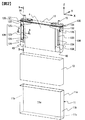
- FIG. 2 is an exploded perspective view showing the configuration of the secondary battery.
- illustration of the gas discharge valve 16 and the liquid injection part 17 is abbreviate
- the secondary battery is provided with a rectangular thin battery container including a battery can 11 and a battery lid 12.
- the battery can 11 accommodates the wound electrode group 4 and has a pair of wide surfaces 11a, a pair of narrow surfaces 11b and a bottom surface 11c, and the upper surface is open. It is formed in a rectangular box shape.
- the wound electrode group 4 is joined to the positive electrode current collector 120 and the negative electrode current collector 130 connected to the battery lid 12 by ultrasonic bonding or the like.
- the wound electrode group 4 is accommodated in the battery can 11 in a state of being covered with the bag-like insulating sheet 13. Thereby, the bottom and side surfaces of the battery can 11 and the wound electrode group 4 are electrically insulated.
- the battery cover 12 has a rectangular flat plate shape and is welded so as to close the opening of the battery can 11 and seals the battery can 11.
- the liquid injection part 17 is provided on the battery cover 12.
- a liquid injection hole for injecting an electrolytic solution into the battery container is bored in the liquid injection portion 17.
- the injection hole is sealed by the injection valve after the injection of the electrolyte.
- the battery cover 12 is also provided with a gas discharge valve 16.
- the gas discharge valve 16 is formed by partially thinning the battery cover 12 by press processing.
- the gas discharge valve 16 generates heat by generating heat due to an abnormality such as overcharging of the secondary battery, and when the pressure in the battery container rises and reaches a predetermined pressure, it is cleaved to discharge the gas from the inside Thereby reducing the pressure in the battery container.
- the battery cover 12 is provided with a positive electrode external terminal 14 and a negative electrode external terminal 15.
- the positive electrode external terminal 14 and the negative electrode external terminal 15 are connected by caulking to the positive electrode current collector 120 and the negative electrode current collector 130 disposed in the battery can 11, respectively.
- the positive electrode external terminal 14, the positive electrode current collector 120, the negative electrode external terminal 15, and the negative electrode current collector 130 are each electrically insulated from the battery lid 12 by an insulating material (not shown).
- the positive electrode external terminal 14 and the positive electrode current collector 120 are both formed of aluminum, and the negative electrode external terminal 15 and the negative electrode current collector 130 are both formed of copper.
- the positive electrode current collector 120 and the negative electrode current collector 130 are respectively joined to the positive electrode 43 and the negative electrode 46 of the wound electrode group 4.
- the positive electrode external terminal 14 is electrically connected to the positive electrode 43 of the wound electrode group 4 through the positive electrode current collector 120, and the negative electrode external terminal 15 is the negative electrode of the wound electrode group 4 through the negative electrode current collector 130. It is electrically connected to 46. Therefore, power is supplied to the external load through the positive electrode external terminal 14 and the negative electrode external terminal 15, or externally generated power is supplied to the wound electrode group 4 through the positive electrode external terminal 14 and the negative electrode external terminal 15. Be charged.
- a plurality of secondary batteries are juxtaposed, and the positive and negative external terminals 14 and 15 of the adjacent secondary batteries are electrically connected by a bus bar made of a metal plate, whereby the plurality of secondary batteries are electrically connected.
- An assembled battery composed of a secondary battery is formed.
- An external thread is formed on each of the positive electrode external terminal 14 and the negative electrode external terminal 15 exposed to the outside of the battery case, and the bus bar is fastened to the positive electrode external terminal 14 and the negative electrode external terminal 15 by a nut.
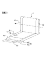
- FIG. 3 is a perspective view of the wound electrode group 4.
- the wound electrode group 4 has a laminated structure by winding the strip-like positive electrode 43 and the negative electrode 46 in a flat shape around the winding central axis W with the separator 47 interposed. ing.
- the positive electrode 43 has a strip-shaped positive electrode foil 41 and a positive electrode active material mixture layer 42 formed by coating a positive electrode active material mixture on both surfaces of the positive electrode foil 41.
- the negative electrode 46 has a negative electrode foil 44 and a negative electrode active material mixture layer 45 formed by coating a negative electrode active material mixture on both surfaces of the negative electrode foil 44.
- the positive electrode foil 41 is an aluminum foil having a thickness of about 20 ⁇ m
- the negative electrode foil 44 is a copper foil having a thickness of about 15 ⁇ m.
- the material of the separator 47 is a porous polyethylene resin.
- the laminated portion of the positive electrode 43 provided at one end is obtained by laminating the positive electrode uncoated portion where the positive electrode active material mixture layer 42 is not formed, that is, the exposed portion of the positive electrode foil 41.
- the laminated portion of the negative electrode 46 provided at the other end is obtained by laminating the uncoated portion of the negative electrode where the negative electrode active material mixture layer 45 is not formed, that is, the exposed portion of the negative electrode foil 44.
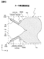
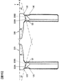
- FIG. 8 is a cross-sectional view taken along the line AA of FIG. 2, schematically showing the battery can 11 by a two-dot chain line.
- the negative electrode side also has the same configuration, so for convenience, reference numerals of constituent elements on the negative electrode side are also attached in parentheses.
- the laminated portion of the positive electrode 43 is crushed in advance, and as shown in FIG. 8, the thickness direction of the wound electrode group 4
- the two bundle electrode connection portions 48 are separated.
- the laminated portion of the negative electrode 46 is squeezed in advance, and as shown in FIG. It is separated into two bundle-like electrode connection parts 49 by being pushed and spread from the thickness direction center side of 4 toward the both wide surfaces 11 a of the battery can 11, that is, outward of the battery can 11.
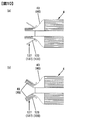
- FIG. 10 is a schematic plan view for explaining the step of forming a bundle electrode connection at the end of the wound electrode group 4.
- FIG. 10A is a schematic view showing a state in which the laminated portion of the positive electrode 43 in the wound electrode group 4 is inserted between a pair of bonding plates 127 provided on the positive electrode current collector 120 described later.
- FIG. 10B is a schematic view showing a state in which the laminated portion of the positive electrode 43 of the wound electrode group 4 inserted is separated from the inside and spread outward so as to be separated into two.
- the configuration on the positive electrode side is shown in FIG. 10, the configuration on the negative electrode side is also the same, so for convenience, reference numerals of constituent elements on the negative electrode side are also attached in parentheses.
- the laminated portion of the positive electrode 43 in the wound electrode group 4 is crushed and deformed in the thickness direction. Keep it. Thereafter, the stacked portion of the crushed positive electrode 43 is inserted between the pair of bonding plates 127, and the stacked portion of the positive electrode 43 is disposed inside the pair of main plates 123 constituting the pair of bonding plates 127.
- the laminated portion is separated into a pair of bundle electrode connection portions 48, and for bonding which can be inserted an ultrasonic oscillation horn between the pair of bundle electrode connection portions 48. Space is formed.
- the pair of bundle electrode connection portions 48 is inclined so as to spread outward, and an electrode bonding surface to be bonded to the positive electrode current collector 120 is provided on the outer surface.
- the laminated portion of the negative electrode 46 in the wound electrode group 4 is crushed in the thickness direction. Let it be deformed. Thereafter, the stacked portion of the crushed negative electrode 46 is inserted between the pair of bonding plates 137, and the stacked portion of the negative electrode 46 is disposed inside the pair of main plates 133 constituting the pair of bonding plates 137.
- the negative electrode current collector 130 After inserting the wound electrode group 4 between the pair of bonding plates 137 of the negative electrode current collector 130, as shown in FIG. 10 (b), the negative electrode current collector 130 is formed on the outer surface of the laminated portion of the negative electrode 46.
- the negative electrode 46 is spread in a V-shape from the inside to the outside so that the inner surface of the main plate 133 is in contact.
- the laminated portion is separated into a pair of bundle electrode connection portions 49, and for bonding which can be inserted an ultrasonic oscillation horn between the pair of bundle electrode connection portions 49. Space is formed.
- the pair of bundle electrode connection portions 49 is inclined so as to spread outward, and an electrode bonding surface to be bonded to the negative electrode current collector 130 is provided on the outer surface.
- the two separated bundle-like electrode connection portions 48 are main plates constituting the bonding plate 127 of the positive electrode current collector 120 on each of the wide sides 11 a side of the battery can 11. It is connected with 123 by ultrasonic bonding.
- the two separated bundle-like electrode connection parts 49 are connected by ultrasonic bonding to the main plate 133 that constitutes the bonding plate 137 of the negative electrode current collector 130 on each of the wide side 11a side of the battery can 11 It is done.
- FIG. 2 the direction of the winding central axis W (see FIG. 3) of the wound electrode group 4 is taken as the X direction, and the thickness direction of the wound electrode group 4 orthogonal to the X direction is taken as the Y direction.
- the height direction (vertical direction) of the wound electrode group 4 orthogonal to the Y direction is taken as the Z direction.
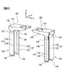
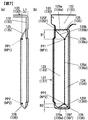
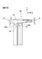
- FIG. 4 is a perspective view showing the positive electrode current collector 120 and the negative electrode current collector 130 of the secondary battery.
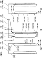
- 5 (a) is a left side view of the positive electrode current collector 120
- FIG. 5 (b) is a front view of the positive electrode current collector 120
- FIG. 5 (c) is a right side view of the positive electrode current collector 120.
- the positive electrode current collector 120 and the negative electrode current collector 130 are formed of the same material although they have different materials. Therefore, although FIG. 5 shows the configuration of the positive electrode current collector 120, for convenience, reference numerals of components of the negative electrode current collector 130 are also attached in parentheses.
- the positive electrode current collector 120 is bent and extended downward from the long side portion of the mounting plate 121 and the rectangular flat plate-like mounting plate 121 to which the positive electrode external terminal 14 is connected.
- a pair of connecting plates 122, and a drawn portion 128 extending from one end of the pair of connecting plates 122 toward the bottom surface 11c of the battery can 11 with a predetermined width.
- the negative electrode current collector 130 includes a rectangular flat plate-like mounting plate 131 to which the negative electrode external terminal 15 is connected, and a pair of connecting plates 132 bent and extended downward from the long side of the mounting plate 131.
- a drawn portion 138 extends from one end of the pair of connection plates 132 toward the bottom surface 11 c of the battery can 11 with a predetermined width.
- the attachment plates 121 and 131 are in contact with the inner surface of the battery lid 12 via an insulating material (not shown), and are disposed along the inner surface of the battery lid 12.
- the mounting plate 121 is provided with an opening for mounting the positive electrode external terminal 14, and the mounting plate 131 is provided with an opening for mounting the negative electrode external terminal 15.
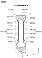
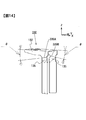
- FIG. 6 is a cross-sectional view taken along the line CC of FIG. 5 (b), schematically illustrating the battery can 11 by a two-dot chain line.
- FIG. 9 is a cross-sectional view taken along the line B--B of FIG. 2, and schematically shows the battery can 11 and the battery lid 12 by a two-dot chain line.
- FIG. 6 and FIG. 9 show the configuration on the positive electrode side, since the negative electrode side is also the same configuration, for convenience, reference numerals of constituent elements on the negative electrode side are also attached in parentheses.
- the pair of connection plates 122 of the positive electrode current collector 120 are bent substantially at right angles from the wide surface 11a side of the battery can 11 in the mounting plate 121 It extends along the both wide faces 11 a of the can 11 toward the bottom surface 11 c of the battery can 11 so as to cover the folded end of the wound electrode group 4.
- the pair of connection plates 132 of the negative electrode current collector 130 are bent substantially at right angles from the both wide surfaces 11 a of the battery can 11 in the mounting plate 131, and the battery cans 11 along the both wide surfaces 11 a of the battery can 11. It extends so as to cover the folded end of the wound electrode group 4 toward the bottom surface 11c of the second embodiment.
- each of the pair of drawn portions 128 of the positive electrode current collector 120 is from the wide surface 11 a side of the battery can 11 toward the center in the thickness direction of the wound electrode group 4. It is formed by the drawing process by a press so that it may protrude, and it is considered as the shape where the surface by the side of the wide surface 11a of the battery can 11 became depressed.
- each of the pair of drawn portions 138 of the negative electrode current collector 130 is drawn by a press so as to protrude from the wide surface 11 a side of the battery can 11 toward the center in the thickness direction of the wound electrode group 4. It is formed and the surface by the side of the wide surface 11a of the battery can 11 is made into the shape which became depressed.
- Each of the pair of drawn portions 128 of the positive electrode current collector 120 has a bonding plate 127, a bonding plate 125, and a reinforcing plate 126, as shown in FIG.
- the bonding plate 127 has an L-shaped cross section (see FIG. 8) by the main plate 123 extending in the z direction (the height direction of the wound electrode group 4) and the rib plate 124.
- the coupling plate 125 couples the connection plate 122, the main plate 123 and the rib plate 124.
- the reinforcing plate 126 couples the main plate 123 and the rib plate 124 at an end on the bottom surface 11 c side of the battery can 11. Similarly, as shown in FIG.
- each of the pair of drawn portions 138 of the negative electrode current collector 130 has a bonding plate 137, a bonding plate 135, and a reinforcing plate 136.
- the bonding plate 137 has an L-shaped cross section (see FIG. 8) by the main plate 133 extending in the z direction (the height direction of the wound electrode group 4) and the rib plate 134.
- the coupling plate 135 couples the connection plate 132, the main plate 133 and the rib plate 134.
- the reinforcing plate 136 couples the main plate 133 and the rib plate 134 at the end on the bottom surface 11 c side of the battery can 11.
- each of the pair of main plates 123 constituting the pair of bonding plates 127 of the positive electrode current collector 120 is the both wide surfaces of the battery can 11 in the two separated bundle electrode connection portions 48. It has a current collector bonding surface bonded to each electrode bonding surface on the side 11a.
- Each of the pair of rib plates 124 constituting the pair of bonding plates 127 of the positive electrode current collector 120 is a wide end portion of the main plate 123, which is an end portion on the center side of the wound electrode group 4. It is bent and extended toward the surface 11 a, that is, outward of the battery can 11.
- each of the pair of main plates 133 constituting the pair of bonding plates 137 of the negative electrode current collector 130 is of the battery can 11 in the two separated bundle electrode connection portions 49. It has a current collector bonding surface to be bonded to each of the electrode bonding surfaces on the both wide surfaces 11 a side.
- Each of the pair of rib plates 134 constituting the pair of bonding plates 137 of the negative electrode current collector 130 is a wide end portion of the main plate 133 which is an end portion on the center side of the wound electrode group 4. It is bent and extended toward the surface 11 a, that is, outward of the battery can 11.
- the rib plate 134 is in contact with the laminated portion of the negative electrode 46 in FIG. 8, it may not be in contact with it.
- the pair of main plates 123 of the positive electrode current collector 120 is closer to the center side of the wound electrode group 4 from the narrow side 11b side of the battery can 11 in the XY plane. It inclines so that the space
- the pair of rib plates 124 of the positive electrode current collector 120 is such that the distance between the rib plates 124 becomes wider from the narrow surface 11 b side of the battery can 11 toward the center side of the wound electrode group 4 in the XY plane. It is inclined to Similarly, as shown in FIGS.
- the pair of main plates 133 of the negative electrode current collector 130 is from the narrow side 11b side of the battery can 11 to the center side of the wound electrode group 4 in the XY plane. It inclines so that the space
- the pair of rib plates 134 of the negative electrode current collector 130 is such that the distance between the rib plates 134 becomes wider from the narrow side 11 b of the battery can 11 toward the center of the wound electrode group 4 in the XY plane. It is inclined to
- each of the pair of coupling plates 125 of the positive electrode current collector 120 is a wound electrode from one end on the bottom surface 11 c side of the battery can 11 in each of the pair of connection plates 122. It inclines toward the center in the thickness direction of the group 4 and extends toward the bottom surface 11 c of the battery can 11.
- Each of the pair of coupling plates 125 of the positive electrode current collector 120 is coupled to one end of each of the pair of bonding plates 127 on the battery lid 12 side.
- each of the pair of coupling plates 135 of the negative electrode current collector 130 is from one end on the bottom surface 11 c side of the battery can 11 in each of the pair of connection plates 132 It is inclined toward the center in the thickness direction of the wound electrode group 4 and extends toward the bottom surface 11 c of the battery can 11.
- Each of the pair of coupling plates 135 of the negative electrode current collector 130 is coupled to one end of each of the pair of bonding plates 137 on the battery lid 12 side.
- each of the pair of reinforcing plates 126 of the positive electrode current collector 120 is a wound electrode group from the end portion of the positive electrode current collector 120 on the bottom surface 11 c side of the battery can 11. It inclines toward the center in the thickness direction of 4 and extends toward the battery lid 12.
- Each of the pair of reinforcing plates 126 of the positive electrode current collector 120 is coupled to the end portion of the main plate 123 of the pair of bonding plates 127 and the rib plate 124 on the bottom surface 11 c side of the battery can 11.
- the coupling plate 125 of the positive electrode current collector 120 includes a substantially triangular coupling surface 125F having a first bending side 129a, a second bending side 129b, and a third bending side 129c.
- the coupling plate 125 of the positive electrode current collector 120 is continuous with one end of the connection plate 122 at a first bending side 129a, is continuous with the main plate 123 of the bonding plate 127 at a second bending side 129b, and is a bonding plate at a third bending side 129c. It is continuous with the rib plate 124 of 127.
- the coupling plate 135 of the negative electrode current collector 130 includes a substantially triangular coupling surface 135F having a first bending side 139a, a second bending side 139b, and a third bending side 139c.
- the bonding plate 135 of the negative electrode current collector 130 is continuous with one end of the connection plate 132 at the first bending side 139a, is continuous with the main plate 133 of the bonding plate 137 at the second bending side 139b, and is the bonding plate at the third bending side 139c. It is continuous with the rib plate 134 of 137.
- the boundary between the main plate 123 and the rib plate 124 on the coupling surface 125F side of the positive electrode current collector 120 is a fourth bending side 129d, and the main plate 123 and the rib plate 124 are continuous at the fourth bending side 129d.
- the boundary between the main plate 133 on the side of the coupling surface 135F of the negative electrode current collector 130 and the rib plate 134 is the fourth bending side 139d, and the main plate 133 and the rib plate 134 are continuous at the fourth bending side 139d.
- the first bent side 129a of the positive electrode current collector 120 is provided in the X direction, that is, parallel to the winding central axis direction.
- Each of the second bending side 129b, the third bending side 129c, and the fourth bending side 129d in the positive electrode current collector 120 is separated from the connection plate 122 by a predetermined distance L1 toward the center of the wound electrode group 4 in the thickness direction,
- the connection plate 122 intersects the bottom surface 11c of the battery can 11 at a point PP1 separated by a predetermined distance B1.
- the second bending side 129b, the third bending side 129c, and the fourth bending side 129d have a Y-shape in a side view.
- the first bending side 139a of the negative electrode current collector 130 is provided in the X direction, that is, parallel to the winding central axis direction.
- Each of the second bending side 139b, the third bending side 139c, and the fourth bending side 139d in the negative electrode current collector 130 is separated from the connection plate 132 by a predetermined distance L1 toward the center in the thickness direction of the wound electrode group 4;
- the connection plate 132 intersects with the bottom surface 11c of the battery can 11 at a point NP1 separated by a predetermined distance B1.
- the second bending side 139b, the third bending side 139c, and the fourth bending side 139d have a Y-shape in a side view.
- the reinforcing plate 126 of the positive electrode current collector 120 has a triangular reinforcing surface 126F having a fifth bending side 129e and a sixth bending side 129f, and an edge connecting the fifth bending side 129e and the sixth bending side 129f.
- the reinforcing plate 126 of the positive electrode current collector 120 is continuous with the main plate 123 of the bonding plate 127 at the fifth bending side 129e and is continuous with the rib plate 124 of the bonding plate 127 at the sixth bending side 129f.
- the reinforcing plate 136 of the negative electrode current collector 130 is a triangular reinforcing member having a fifth bending side 139e and a sixth bending side 139f, and an edge connecting the fifth bending side 139e and the sixth bending side 139f. It has a surface 136F.
- the reinforcing plate 136 of the negative electrode current collector 130 is continuous with the main plate 133 of the bonding plate 137 at the fifth bending side 139 e and is continuous with the rib plate 134 of the bonding plate 137 at the sixth bending side 139 f.
- Each of the fifth bending side 129e, the sixth bending side 129f, and the fourth bending side 129d of the positive electrode current collector 120 is separated from the connection plate 122 by a predetermined distance L1 toward the center of the wound electrode group 4 in the thickness direction,
- the end of the positive electrode current collector 120 on the battery can bottom 11 c side intersects with the battery lid 12 at a point PP 2 separated by a predetermined distance B 2.
- the fifth bending side 129e, the sixth bending side 129f, and the fourth bending side 129d have an inverted Y shape in a side view.
- each of the fifth bending side 139e, the sixth bending side 139f, and the fourth bending side 139d of the negative electrode current collector 130 is separated from the connection plate 132 by a predetermined distance L1 toward the center of the wound electrode group 4 in the thickness direction.
- the end of the negative electrode current collector 130 on the battery can bottom surface 11 c side intersects with the battery lid 12 at a point NP 2 separated by a predetermined distance B 2.
- the fifth bending side 139e, the sixth bending side 139f, and the fourth bending side 139d have an inverted Y shape in a side view.
- a pair of connecting plates 125 are provided to connect each of the pair of connecting plates 122 extending from the mounting plate 121 along the inner surface of the housing 11 to the bottom surface 11 c of the battery can 11.
- the positive electrode current collector 120 Since the junction plate 127 and the connection plate 122 are three-dimensionally coupled by the coupling plate 125, the positive electrode current collector 120 has improved rigidity against vibration and impact in the X, Y, and Z directions, and vibration applied to the secondary battery It is possible to prevent the deformation of the positive electrode current collector 120 due to shock or impact.
- a pair of connecting plates 135 are provided to connect each of the pair of connecting plates 132 extending from the mounting plate 131 along the inner surface of the housing to the bottom surface 11 c of the battery can 11. Since the bonding plate 137 and the connection plate 132 are three-dimensionally connected by the bonding plate 135, the rigidity of the negative electrode current collector 130 against vibration and impact in the X, Y, and Z directions is improved, and the vibration applied to the secondary battery And deformation of the negative electrode current collector 130 caused by impact can be prevented.
- the drawn portion 128 consisting of the connecting plate 125, the main plate 123, the rib plate 124 and the reinforcing plate 126 can be integrally formed by drawing with a press, so the positive electrode current collector 120 can be manufactured at low cost. It can be manufactured.
- the drawn portion 138 consisting of the coupling plate 135, the main plate 133, the rib plate 134 and the reinforcing plate 136 can be integrally formed by drawing with a press, the negative electrode current collector 130 can be manufactured at low cost. It can be manufactured.
- FIGS. 11 and 12 A secondary battery according to a second embodiment will be described with reference to FIGS. 11 and 12.
- the same or corresponding parts as in the first embodiment are designated by the same reference numerals, and the description will be omitted.
- the difference from the first embodiment will be described in detail.
- FIG. 11 is a perspective view showing a positive electrode current collector 220 and a negative electrode current collector 230 of a secondary battery according to a second embodiment of the present invention
- FIG. 12 relates to the second embodiment of the present invention
- FIG. 10 is a side cross-sectional view showing the positive electrode current collector 220 of the secondary battery and the wound electrode group 4, and corresponds to FIG. 9.
- FIG. 12 shows the configuration of the positive electrode current collector 220, for convenience, reference numerals of components of the negative electrode current collector 230 are also attached in parentheses.
- the same effect as that of the first embodiment can be obtained. Furthermore, in the second embodiment, since it is not necessary to form the reinforcing plates 126 and 136, it is possible to manufacture the positive electrode current collector 220 and the negative electrode current collector 230 at low cost as compared with the first embodiment. it can. Thereby, the cost of the secondary battery can be reduced.
- the mass of the wound electrode group 4 is smaller than that of the first embodiment, and the main plates 123 and 133, the rib plates 124 and 134, and the connection plate 122 are formed by the coupling plates 125 and 135, respectively. , 132 are useful when sufficient rigidity can be obtained by combining them.
- FIG. 13 is a perspective view showing a positive electrode current collector 320 of a secondary battery according to a third embodiment of the present invention
- FIG. 14 is a perspective view showing a negative electrode current collector 330.
- FIG. 15 is a side view of the positive electrode current collector 320 of FIG. 13 and the negative electrode current collector 330 of FIG.
- the same or corresponding parts as in the first and second embodiments are designated by the same reference numerals, and the description will be omitted.
- the difference from the second embodiment will be described in detail.
- each of the first bending sides 329A, 329B, 339A, 339B is a predetermined X direction which is a winding central axis direction of the winding electrode group 4. It is provided to make an angle ⁇ .
- the pair of first bending sides 329A and 329B in each of the pair of coupling plates 125 provided on the positive electrode current collector 320 are the coupling plate 125 and the connection plate 122 on the left side as viewed in the drawing.
- the first bending side 329B which is the boundary between the coupling plate 125 and the connection plate 122 on the right side in the drawing, point Q1 in side view as shown in FIG. are provided to cross each other.
- the pair of first bent sides 339A and 339B in each of the pair of coupling plates 135 provided on the negative electrode current collector 330 is connected to the coupling plate 135 on the left side in the drawing sheet.
- a first bending side 339A which is a boundary with the plate 132, and a first bending side 339B which is a boundary between the coupling plate 135 and the connection plate 132 on the right side in the drawing, as shown in FIG. are provided so as to intersect at point Q2.
- the same effect as that of the second embodiment can be obtained. Furthermore, in the third embodiment, the rigidity against vibration or impact in the Y direction is enhanced as compared to the second embodiment in which the pair of first bending sides are provided parallel to the X direction. it can.
- the coupling plate 425 of the positive electrode current collector 420 has a substantially trapezoidal coupling surface 425F and integrally couples the main plate 423, the rib plate 424, the bottom plate 427a, and the connection plate 122.
- the reinforcing plate 426 of the positive electrode current collector 420 has a trapezoidal reinforcing surface 426 F, and at the end of the positive electrode current collector 420 on the bottom surface 11 c side of the battery can 11, the main plate 423, the rib plate 424 and the bottom plate 427 a It is connected.
- the coupling plate 435 of the negative electrode current collector 430 has a substantially trapezoidal coupling surface 435 F and integrally couples the main plate 433, the rib plate 434, the bottom plate 437 a, and the connection plate 132.
- the reinforcing plate 436 of the negative electrode current collector 430 has a trapezoidal reinforcing surface 436 F, and at the end of the negative electrode current collector 430 on the bottom surface 11 c side of the battery can 11, the main plate 433, the rib plate 434 and the bottom plate 437 a It is connected.
- the coupling plate 535 of the negative electrode current collector 530 is provided with a coupling surface 535F having a linear first bending side 139a and a curved bending side 539g.
- the reinforcing plate 536 of the negative electrode current collector 530 is provided with a reinforcing surface 536F having an edge on the bottom surface 11c side of the battery can 11 and a curved bending edge 539h.
- the material of the positive electrode external terminal, the positive electrode current collector and the positive electrode foil is not limited to aluminum, and may be an aluminum alloy.
- the material of the negative electrode external terminal, the negative electrode current collector and the negative electrode foil is not limited to copper, and may be a copper alloy.
Landscapes
- Chemical & Material Sciences (AREA)
- Chemical Kinetics & Catalysis (AREA)
- Electrochemistry (AREA)
- General Chemical & Material Sciences (AREA)
- Engineering & Computer Science (AREA)
- Manufacturing & Machinery (AREA)
- Connection Of Batteries Or Terminals (AREA)
- Secondary Cells (AREA)
Abstract
L'invention concerne une batterie secondaire qui comprend un groupe électrode enroulée, un boîtier de batterie, un capuchon de batterie, des bornes externes disposées sur le capuchon de batterie, et des collecteurs connectant le groupe électrode enroulée et les bornes externes. La partie enroulée d'une électrode constituant le groupe électrode enroulée est divisée à partir du côté du centre, dans la direction de l'épaisseur, du groupe électrode enroulée vers l'extérieur du boîtier de batterie, en deux parties de connexion d'électrode en faisceau. Les collecteurs comprennent chacun : des plaques de liaison ayant des plaques principales liées aux parties de connexion d'électrode en faisceau et des plaques cintrées à nervures et s'étendant des plaques principales vers l'extérieur du boîtier de batterie ; une plaque de fixation qui se situe le long de la surface interne du capuchon de batterie ; des plaques de connexion cintrées à partir des parties latérales de la plaque de fixation et s'étendant vers la partie inférieure du boîtier de batterie ; et des plaques d'assemblage destinées à assembler les plaques de connexion et les plaques de liaison. Les plaques d'assemblage sont inclinées à partir d'une extrémité côté partie inférieure de boîtier de batterie des plaques de connexion vers le centre, dans la direction de l'épaisseur, du groupe électrodes enroulée, et s'étendent vers la partie inférieure du boîtier de batterie. Les plaques d'assemblage assemblent une extrémité côté capuchon de batterie des plaques de liaison.
Priority Applications (1)
| Application Number | Priority Date | Filing Date | Title |
|---|---|---|---|
| US14/128,983 US9252453B2 (en) | 2011-06-24 | 2012-06-15 | Rechargeable battery |
Applications Claiming Priority (2)
| Application Number | Priority Date | Filing Date | Title |
|---|---|---|---|
| JP2011-140524 | 2011-06-24 | ||
| JP2011140524A JP5663415B2 (ja) | 2011-06-24 | 2011-06-24 | 二次電池 |
Publications (1)
| Publication Number | Publication Date |
|---|---|
| WO2012176704A1 true WO2012176704A1 (fr) | 2012-12-27 |
Family
ID=47422542
Family Applications (1)
| Application Number | Title | Priority Date | Filing Date |
|---|---|---|---|
| PCT/JP2012/065343 WO2012176704A1 (fr) | 2011-06-24 | 2012-06-15 | Batterie secondaire |
Country Status (3)
| Country | Link |
|---|---|
| US (1) | US9252453B2 (fr) |
| JP (1) | JP5663415B2 (fr) |
| WO (1) | WO2012176704A1 (fr) |
Cited By (5)
| Publication number | Priority date | Publication date | Assignee | Title |
|---|---|---|---|---|
| JP2015141847A (ja) * | 2014-01-29 | 2015-08-03 | 株式会社東芝 | 二次電池、及び二次電池の製造方法 |
| CN106129429A (zh) * | 2016-09-05 | 2016-11-16 | 宁德时代新能源科技股份有限公司 | 电池 |
| US20170229699A1 (en) * | 2014-10-31 | 2017-08-10 | Bayerische Motoren Werke Aktiengesellschaft | Current Collector for an Electrochemical Energy Storage Apparatus |
| CN108198989A (zh) * | 2018-01-16 | 2018-06-22 | 宁德时代新能源科技股份有限公司 | 连接构件和充电电池 |
| CN108199072A (zh) * | 2018-01-16 | 2018-06-22 | 宁德时代新能源科技股份有限公司 | 充电电池 |
Families Citing this family (14)
| Publication number | Priority date | Publication date | Assignee | Title |
|---|---|---|---|---|
| JP6024088B2 (ja) * | 2011-09-30 | 2016-11-09 | 株式会社Gsユアサ | 蓄電装置 |
| JP5930162B2 (ja) * | 2011-12-14 | 2016-06-08 | 三菱自動車工業株式会社 | 電池 |
| JP6149570B2 (ja) * | 2013-07-22 | 2017-06-21 | 株式会社Gsユアサ | 蓄電素子 |
| JP6269092B2 (ja) * | 2014-01-17 | 2018-01-31 | 株式会社Gsユアサ | 蓄電素子 |
| KR102278449B1 (ko) * | 2014-04-07 | 2021-07-16 | 삼성에스디아이 주식회사 | 이차 전지 |
| WO2016000474A1 (fr) * | 2014-06-30 | 2016-01-07 | Byd Company Limited | Connecteur pour batterie et batterie comprenant celui-ci |
| KR102306440B1 (ko) * | 2014-08-14 | 2021-09-29 | 삼성에스디아이 주식회사 | 이차 전지 |
| WO2016047199A1 (fr) * | 2014-09-26 | 2016-03-31 | 日立オートモティブシステムズ株式会社 | Batterie rechargeable rectangulaire |
| US10058025B2 (en) | 2015-01-13 | 2018-08-28 | Meterio Micheal LONSWAY | In-line soluble media delivery system |
| JP6562726B2 (ja) * | 2015-06-11 | 2019-08-21 | 日立オートモティブシステムズ株式会社 | 角形二次電池及びその製造方法 |
| WO2017110548A1 (fr) * | 2015-12-24 | 2017-06-29 | 株式会社 豊田自動織機 | Dispositif de stockage d'énergie |
| WO2019088053A1 (fr) | 2017-10-30 | 2019-05-09 | 株式会社東芝 | Batterie et procédé permettant de fabriquer une batterie |
| CN111864172A (zh) | 2019-04-25 | 2020-10-30 | 宁德时代新能源科技股份有限公司 | 电池单元和电池模组 |
| CN117157822A (zh) * | 2021-07-29 | 2023-12-01 | 日本汽车能源株式会社 | 二次电池 |
Citations (10)
| Publication number | Priority date | Publication date | Assignee | Title |
|---|---|---|---|---|
| JP2000150306A (ja) * | 1998-11-12 | 2000-05-30 | Toyota Motor Corp | 電池またはキャパシタの集電方式 |
| JP2003346771A (ja) * | 2002-05-28 | 2003-12-05 | Japan Storage Battery Co Ltd | 電 池 |
| JP2006228551A (ja) * | 2005-02-17 | 2006-08-31 | Toyota Motor Corp | 集電端子及び該端子を備えた蓄電装置 |
| JP2009026705A (ja) * | 2007-07-23 | 2009-02-05 | Toyota Motor Corp | 電池 |
| WO2010001975A1 (fr) * | 2008-07-02 | 2010-01-07 | 株式会社ジーエス・ユアサコーポレーション | Batterie et son procédé de fabrication |
| JP2010257945A (ja) * | 2009-04-21 | 2010-11-11 | Sb Limotive Co Ltd | 2次電池 |
| WO2010147136A1 (fr) * | 2009-06-17 | 2010-12-23 | 株式会社Gsユアサ | Batterie et procédé de production de batterie |
| JP2011171286A (ja) * | 2010-02-18 | 2011-09-01 | Sb Limotive Co Ltd | 二次電池及び電池モジュール |
| JP2011192517A (ja) * | 2010-03-15 | 2011-09-29 | Hitachi Vehicle Energy Ltd | 角形電池およびその製造方法 |
| WO2012086427A1 (fr) * | 2010-12-20 | 2012-06-28 | 株式会社Gsユアサ | Élément de stockage d'électricité possédant un collecteur et véhicule équipé de l'élément de stockage d'électricité |
Family Cites Families (4)
| Publication number | Priority date | Publication date | Assignee | Title |
|---|---|---|---|---|
| JP4588331B2 (ja) | 2004-02-02 | 2010-12-01 | パナソニック株式会社 | 角形電池とその製造方法 |
| JP5430978B2 (ja) * | 2009-03-10 | 2014-03-05 | 三洋電機株式会社 | 密閉電池及びその製造方法 |
| EP2528143B1 (fr) * | 2010-08-19 | 2020-11-04 | GS Yuasa International Ltd. | Élément de stockage d'énergie comportant un collecteur de courant, et procédé de fabrication d'un collecteur de courant |
| US8889292B2 (en) * | 2011-10-13 | 2014-11-18 | Samsung Sdi Co., Ltd. | Rechargeable battery |
-
2011
- 2011-06-24 JP JP2011140524A patent/JP5663415B2/ja active Active
-
2012
- 2012-06-15 US US14/128,983 patent/US9252453B2/en active Active
- 2012-06-15 WO PCT/JP2012/065343 patent/WO2012176704A1/fr active Application Filing
Patent Citations (10)
| Publication number | Priority date | Publication date | Assignee | Title |
|---|---|---|---|---|
| JP2000150306A (ja) * | 1998-11-12 | 2000-05-30 | Toyota Motor Corp | 電池またはキャパシタの集電方式 |
| JP2003346771A (ja) * | 2002-05-28 | 2003-12-05 | Japan Storage Battery Co Ltd | 電 池 |
| JP2006228551A (ja) * | 2005-02-17 | 2006-08-31 | Toyota Motor Corp | 集電端子及び該端子を備えた蓄電装置 |
| JP2009026705A (ja) * | 2007-07-23 | 2009-02-05 | Toyota Motor Corp | 電池 |
| WO2010001975A1 (fr) * | 2008-07-02 | 2010-01-07 | 株式会社ジーエス・ユアサコーポレーション | Batterie et son procédé de fabrication |
| JP2010257945A (ja) * | 2009-04-21 | 2010-11-11 | Sb Limotive Co Ltd | 2次電池 |
| WO2010147136A1 (fr) * | 2009-06-17 | 2010-12-23 | 株式会社Gsユアサ | Batterie et procédé de production de batterie |
| JP2011171286A (ja) * | 2010-02-18 | 2011-09-01 | Sb Limotive Co Ltd | 二次電池及び電池モジュール |
| JP2011192517A (ja) * | 2010-03-15 | 2011-09-29 | Hitachi Vehicle Energy Ltd | 角形電池およびその製造方法 |
| WO2012086427A1 (fr) * | 2010-12-20 | 2012-06-28 | 株式会社Gsユアサ | Élément de stockage d'électricité possédant un collecteur et véhicule équipé de l'élément de stockage d'électricité |
Cited By (14)
| Publication number | Priority date | Publication date | Assignee | Title |
|---|---|---|---|---|
| US10418612B2 (en) | 2014-01-29 | 2019-09-17 | Kabushiki Kaisha Toshiba | Secondary battery and a method of manufacturing secondary battery |
| WO2015115494A1 (fr) * | 2014-01-29 | 2015-08-06 | 株式会社 東芝 | Pile rechargeable et procédé de fabrication de pile rechargeable |
| CN105917512A (zh) * | 2014-01-29 | 2016-08-31 | 株式会社东芝 | 二次电池和二次电池的制造方法 |
| JP2015141847A (ja) * | 2014-01-29 | 2015-08-03 | 株式会社東芝 | 二次電池、及び二次電池の製造方法 |
| EP3101723A4 (fr) * | 2014-01-29 | 2017-06-28 | Kabushiki Kaisha Toshiba | Pile rechargeable et procédé de fabrication de pile rechargeable |
| US20170229699A1 (en) * | 2014-10-31 | 2017-08-10 | Bayerische Motoren Werke Aktiengesellschaft | Current Collector for an Electrochemical Energy Storage Apparatus |
| US10700336B2 (en) * | 2014-10-31 | 2020-06-30 | Bayerische Motoren Werke Aktiengesellschaft | Current collector for electrochemical energy storage apparatus |
| CN106129429A (zh) * | 2016-09-05 | 2016-11-16 | 宁德时代新能源科技股份有限公司 | 电池 |
| CN108199072A (zh) * | 2018-01-16 | 2018-06-22 | 宁德时代新能源科技股份有限公司 | 充电电池 |
| CN108198989A (zh) * | 2018-01-16 | 2018-06-22 | 宁德时代新能源科技股份有限公司 | 连接构件和充电电池 |
| US10826047B2 (en) | 2018-01-16 | 2020-11-03 | Contemporary Amperex Technology Co., Limited | Rechargeable battery |
| CN108198989B (zh) * | 2018-01-16 | 2021-01-12 | 宁德时代新能源科技股份有限公司 | 连接构件和充电电池 |
| US10910622B2 (en) | 2018-01-16 | 2021-02-02 | Contemporary Amperex Technology Co., Limited | Connection member and rechargeable battery |
| US11929521B2 (en) | 2018-01-16 | 2024-03-12 | Contemporary Amperex Technology Co., Limited | Rechargeable battery |
Also Published As
| Publication number | Publication date |
|---|---|
| US20140120396A1 (en) | 2014-05-01 |
| US9252453B2 (en) | 2016-02-02 |
| JP5663415B2 (ja) | 2015-02-04 |
| JP2013008559A (ja) | 2013-01-10 |
Similar Documents
| Publication | Publication Date | Title |
|---|---|---|
| WO2012176704A1 (fr) | Batterie secondaire | |
| KR101121332B1 (ko) | 전지 | |
| US10135056B2 (en) | Energy storage device | |
| US20120301759A1 (en) | Electric storage device and insulation cover | |
| JP5594901B2 (ja) | 二次電池 | |
| US10644296B2 (en) | Energy storage device | |
| JP2019053863A (ja) | 蓄電素子 | |
| JP6269092B2 (ja) | 蓄電素子 | |
| JP6192992B2 (ja) | 角形二次電池 | |
| JP6184747B2 (ja) | 角形二次電池 | |
| JP5768002B2 (ja) | 二次電池 | |
| JP2019061892A (ja) | 蓄電素子 | |
| JP6311323B2 (ja) | 蓄電素子 | |
| JP7035419B2 (ja) | 蓄電素子 | |
| JP2019061881A (ja) | 蓄電素子 | |
| JP6133680B2 (ja) | 角形二次電池 | |
| WO2018235768A1 (fr) | Élément accumulateur de puissance | |
| JP2015095404A (ja) | 蓄電素子及びその製造方法 | |
| JP2019061893A (ja) | 蓄電素子 | |
| JP5831213B2 (ja) | 二次電池、車両 | |
| JP2019061880A (ja) | 蓄電素子 | |
| JP7259261B2 (ja) | 蓄電素子 | |
| JP7039913B2 (ja) | 蓄電素子 | |
| JP2023038811A (ja) | 蓄電素子 | |
| CN117954809A (zh) | 电池 |
Legal Events
| Date | Code | Title | Description |
|---|---|---|---|
| 121 | Ep: the epo has been informed by wipo that ep was designated in this application |
Ref document number: 12803260 Country of ref document: EP Kind code of ref document: A1 |
|
| WWE | Wipo information: entry into national phase |
Ref document number: 14128983 Country of ref document: US |
|
| NENP | Non-entry into the national phase |
Ref country code: DE |
|
| 122 | Ep: pct application non-entry in european phase |
Ref document number: 12803260 Country of ref document: EP Kind code of ref document: A1 |