WO2012176704A1 - Secondary battery - Google Patents
Secondary battery Download PDFInfo
- Publication number
- WO2012176704A1 WO2012176704A1 PCT/JP2012/065343 JP2012065343W WO2012176704A1 WO 2012176704 A1 WO2012176704 A1 WO 2012176704A1 JP 2012065343 W JP2012065343 W JP 2012065343W WO 2012176704 A1 WO2012176704 A1 WO 2012176704A1
- Authority
- WO
- WIPO (PCT)
- Prior art keywords
- battery
- plate
- current collector
- negative electrode
- positive electrode
- Prior art date
Links
Images


Classifications
-
- H—ELECTRICITY
- H01—ELECTRIC ELEMENTS
- H01M—PROCESSES OR MEANS, e.g. BATTERIES, FOR THE DIRECT CONVERSION OF CHEMICAL ENERGY INTO ELECTRICAL ENERGY
- H01M10/00—Secondary cells; Manufacture thereof
- H01M10/04—Construction or manufacture in general
- H01M10/0431—Cells with wound or folded electrodes
-
- H—ELECTRICITY
- H01—ELECTRIC ELEMENTS
- H01M—PROCESSES OR MEANS, e.g. BATTERIES, FOR THE DIRECT CONVERSION OF CHEMICAL ENERGY INTO ELECTRICAL ENERGY
- H01M4/00—Electrodes
- H01M4/02—Electrodes composed of, or comprising, active material
- H01M4/64—Carriers or collectors
- H01M4/70—Carriers or collectors characterised by shape or form
-
- H—ELECTRICITY
- H01—ELECTRIC ELEMENTS
- H01M—PROCESSES OR MEANS, e.g. BATTERIES, FOR THE DIRECT CONVERSION OF CHEMICAL ENERGY INTO ELECTRICAL ENERGY
- H01M50/00—Constructional details or processes of manufacture of the non-active parts of electrochemical cells other than fuel cells, e.g. hybrid cells
- H01M50/10—Primary casings, jackets or wrappings of a single cell or a single battery
- H01M50/172—Arrangements of electric connectors penetrating the casing
- H01M50/174—Arrangements of electric connectors penetrating the casing adapted for the shape of the cells
- H01M50/176—Arrangements of electric connectors penetrating the casing adapted for the shape of the cells for prismatic or rectangular cells
-
- H—ELECTRICITY
- H01—ELECTRIC ELEMENTS
- H01M—PROCESSES OR MEANS, e.g. BATTERIES, FOR THE DIRECT CONVERSION OF CHEMICAL ENERGY INTO ELECTRICAL ENERGY
- H01M50/00—Constructional details or processes of manufacture of the non-active parts of electrochemical cells other than fuel cells, e.g. hybrid cells
- H01M50/50—Current conducting connections for cells or batteries
- H01M50/531—Electrode connections inside a battery casing
- H01M50/533—Electrode connections inside a battery casing characterised by the shape of the leads or tabs
-
- H—ELECTRICITY
- H01—ELECTRIC ELEMENTS
- H01M—PROCESSES OR MEANS, e.g. BATTERIES, FOR THE DIRECT CONVERSION OF CHEMICAL ENERGY INTO ELECTRICAL ENERGY
- H01M50/00—Constructional details or processes of manufacture of the non-active parts of electrochemical cells other than fuel cells, e.g. hybrid cells
- H01M50/50—Current conducting connections for cells or batteries
- H01M50/531—Electrode connections inside a battery casing
- H01M50/538—Connection of several leads or tabs of wound or folded electrode stacks
-
- H—ELECTRICITY
- H01—ELECTRIC ELEMENTS
- H01M—PROCESSES OR MEANS, e.g. BATTERIES, FOR THE DIRECT CONVERSION OF CHEMICAL ENERGY INTO ELECTRICAL ENERGY
- H01M50/00—Constructional details or processes of manufacture of the non-active parts of electrochemical cells other than fuel cells, e.g. hybrid cells
- H01M50/50—Current conducting connections for cells or batteries
- H01M50/543—Terminals
- H01M50/547—Terminals characterised by the disposition of the terminals on the cells
- H01M50/55—Terminals characterised by the disposition of the terminals on the cells on the same side of the cell
-
- H—ELECTRICITY
- H01—ELECTRIC ELEMENTS
- H01M—PROCESSES OR MEANS, e.g. BATTERIES, FOR THE DIRECT CONVERSION OF CHEMICAL ENERGY INTO ELECTRICAL ENERGY
- H01M50/00—Constructional details or processes of manufacture of the non-active parts of electrochemical cells other than fuel cells, e.g. hybrid cells
- H01M50/50—Current conducting connections for cells or batteries
- H01M50/543—Terminals
- H01M50/552—Terminals characterised by their shape
- H01M50/553—Terminals adapted for prismatic, pouch or rectangular cells
-
- H—ELECTRICITY
- H01—ELECTRIC ELEMENTS
- H01M—PROCESSES OR MEANS, e.g. BATTERIES, FOR THE DIRECT CONVERSION OF CHEMICAL ENERGY INTO ELECTRICAL ENERGY
- H01M2220/00—Batteries for particular applications
- H01M2220/20—Batteries in motive systems, e.g. vehicle, ship, plane
-
- Y—GENERAL TAGGING OF NEW TECHNOLOGICAL DEVELOPMENTS; GENERAL TAGGING OF CROSS-SECTIONAL TECHNOLOGIES SPANNING OVER SEVERAL SECTIONS OF THE IPC; TECHNICAL SUBJECTS COVERED BY FORMER USPC CROSS-REFERENCE ART COLLECTIONS [XRACs] AND DIGESTS
- Y02—TECHNOLOGIES OR APPLICATIONS FOR MITIGATION OR ADAPTATION AGAINST CLIMATE CHANGE
- Y02E—REDUCTION OF GREENHOUSE GAS [GHG] EMISSIONS, RELATED TO ENERGY GENERATION, TRANSMISSION OR DISTRIBUTION
- Y02E60/00—Enabling technologies; Technologies with a potential or indirect contribution to GHG emissions mitigation
- Y02E60/10—Energy storage using batteries
-
- Y—GENERAL TAGGING OF NEW TECHNOLOGICAL DEVELOPMENTS; GENERAL TAGGING OF CROSS-SECTIONAL TECHNOLOGIES SPANNING OVER SEVERAL SECTIONS OF THE IPC; TECHNICAL SUBJECTS COVERED BY FORMER USPC CROSS-REFERENCE ART COLLECTIONS [XRACs] AND DIGESTS
- Y02—TECHNOLOGIES OR APPLICATIONS FOR MITIGATION OR ADAPTATION AGAINST CLIMATE CHANGE
- Y02P—CLIMATE CHANGE MITIGATION TECHNOLOGIES IN THE PRODUCTION OR PROCESSING OF GOODS
- Y02P70/00—Climate change mitigation technologies in the production process for final industrial or consumer products
- Y02P70/50—Manufacturing or production processes characterised by the final manufactured product
Definitions
- the present invention relates to a secondary battery mounted in a vehicle such as a hybrid electric vehicle or a pure electric vehicle.
- a rectangular secondary battery which is accommodated in the battery case of the above and provided with an external terminal electrically connected to the flat electrode group is widely known as a vehicle drive battery (see Patent Document 1).
- Patent Document 1 a current collector having a substantially V-shaped cross section is inserted into the flat electrode group, and the laminated portion of the uncoated portion of the flat electrode group is divided into two and bundled. A structure has been proposed to connect the bundle to the current collector.
- the positive electrode current collector is formed by raising a connection piece from one end of one of the bonding plates, and one end of a lead plate in which the connection piece is connected to an external terminal. Is joined by spot welding to the connection piece suspended from the bottom.
- the negative electrode current collector is bent from one end of one bonding plate to the other bonding plate, and a connecting piece extending long outwardly is formed so as to protrude from the one end, and this connecting piece forms a lead plate. It is connected.
- the lead plate is disposed along the inner surface of the case, and the L-shaped connecting portion is bent from the upper and lower ends thereof, and the connecting portion at the upper end is joined by spot welding or the like to the sealing plate constituting the negative electrode external terminal.
- the lower end connection portion is joined to the connection piece of the negative electrode current collector by spot welding or the like.
- the secondary battery according to the first aspect of the present invention seals a flat electrode group in which a positive electrode and a negative electrode are wound with a separator interposed, a battery can containing the flat electrode group, and a battery can.
- Battery cover positive electrode external terminal and negative electrode external terminal provided on battery cover, positive electrode current collector connecting positive electrode and positive electrode external terminal, negative electrode current collector connecting negative electrode and negative electrode external terminal
- each of the laminated portions of the positive electrode and the negative electrode is a bundle of two toward the outside of the battery can from the center side in the thickness direction of the flat electrode group.
- the coupling plate includes a coupling surface having three bending sides, and is continuous with one end of the connecting plate at the first bending side, the second It is preferable to be continuous with each of the main plate and the rib plate of the joint plate at the bending side and the third bending side.
- the boundary between the main plate on the coupling surface side and the rib plate is a fourth bending side
- the second, third and fourth bending sides Are each separated by a predetermined distance from the connection plate to the center side in the thickness direction of the flat electrode group and from the one end of the connection plate to the bottom side of the battery can by a predetermined distance. It is preferable that it has a Y-shape in a side view by the fourth bending side.
- the first bent side is provided to form a predetermined angle with the winding central axis direction of the flat electrode group, and the positive electrode collection
- the first bending side of each of the pair of coupling plates provided on each of the current collector and the negative electrode current collector is provided such that the first bending sides of each of the pair of coupling plates cross each other in side view Is preferred.
- the main plate and the rib plate are provided on the end of the positive electrode current collector and the negative electrode current collector on the bottom side of the battery can.
- a reinforcing plate is provided to connect the two.
- the positive electrode current collector is connected to the positive electrode external terminal at the other end of the connection plate, and the negative electrode current collector Is preferably connected to the negative electrode external terminal at the other end of the connection plate.
- the present invention it is possible to provide a secondary battery excellent in vibration resistance and impact resistance by preventing deformation of the current collector caused by vibration or impact applied to the secondary battery.
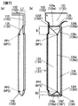
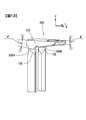
- FIG. 1 is a perspective view showing the appearance of a secondary battery according to a first embodiment of the present invention.
- FIG. 2 is a perspective view showing a wound electrode group of the secondary battery of FIG. 1;
- FIG. 2 is a perspective view showing a positive electrode current collector and a negative electrode current collector of the secondary battery of FIG. 1;
- (A) is a left side view of the current collector,
- (b) is a front view of the current collector, and (c) is a right side view of the current collector.
- (A) is the elements on larger scale of Fig.5 (a),
- (b) is the elements on larger scale of FIG.5 (b).
- FIG. 7 is a perspective view showing a positive electrode current collector and a negative electrode current collector of a secondary battery according to a second embodiment of the present invention.
- FIG. 6 is a side cross-sectional view showing a current collector and a wound electrode group of a secondary battery according to a second embodiment of the present invention.
- FIG. 10 is a perspective view showing a positive electrode current collector of a secondary battery according to a third embodiment of the present invention.
- FIG. 10 is a perspective view showing a negative electrode current collector of a secondary battery according to a third embodiment of the present invention.
- the side view of the positive electrode collector of FIG. 13 and the negative electrode collector of FIG. The elements on larger scale which show the left side of the collector of the secondary battery which concerns on the modification of this invention, and the elements on larger scale which show the front of a collector.
- FIG. 1 is an external perspective view of a secondary battery.
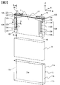
- FIG. 2 is an exploded perspective view showing the configuration of the secondary battery.
- illustration of the gas discharge valve 16 and the liquid injection part 17 is abbreviate
- the secondary battery is provided with a rectangular thin battery container including a battery can 11 and a battery lid 12.
- the battery can 11 accommodates the wound electrode group 4 and has a pair of wide surfaces 11a, a pair of narrow surfaces 11b and a bottom surface 11c, and the upper surface is open. It is formed in a rectangular box shape.
- the wound electrode group 4 is joined to the positive electrode current collector 120 and the negative electrode current collector 130 connected to the battery lid 12 by ultrasonic bonding or the like.
- the wound electrode group 4 is accommodated in the battery can 11 in a state of being covered with the bag-like insulating sheet 13. Thereby, the bottom and side surfaces of the battery can 11 and the wound electrode group 4 are electrically insulated.
- the battery cover 12 has a rectangular flat plate shape and is welded so as to close the opening of the battery can 11 and seals the battery can 11.
- the liquid injection part 17 is provided on the battery cover 12.
- a liquid injection hole for injecting an electrolytic solution into the battery container is bored in the liquid injection portion 17.
- the injection hole is sealed by the injection valve after the injection of the electrolyte.
- the battery cover 12 is also provided with a gas discharge valve 16.
- the gas discharge valve 16 is formed by partially thinning the battery cover 12 by press processing.
- the gas discharge valve 16 generates heat by generating heat due to an abnormality such as overcharging of the secondary battery, and when the pressure in the battery container rises and reaches a predetermined pressure, it is cleaved to discharge the gas from the inside Thereby reducing the pressure in the battery container.
- the battery cover 12 is provided with a positive electrode external terminal 14 and a negative electrode external terminal 15.
- the positive electrode external terminal 14 and the negative electrode external terminal 15 are connected by caulking to the positive electrode current collector 120 and the negative electrode current collector 130 disposed in the battery can 11, respectively.
- the positive electrode external terminal 14, the positive electrode current collector 120, the negative electrode external terminal 15, and the negative electrode current collector 130 are each electrically insulated from the battery lid 12 by an insulating material (not shown).
- the positive electrode external terminal 14 and the positive electrode current collector 120 are both formed of aluminum, and the negative electrode external terminal 15 and the negative electrode current collector 130 are both formed of copper.
- the positive electrode current collector 120 and the negative electrode current collector 130 are respectively joined to the positive electrode 43 and the negative electrode 46 of the wound electrode group 4.
- the positive electrode external terminal 14 is electrically connected to the positive electrode 43 of the wound electrode group 4 through the positive electrode current collector 120, and the negative electrode external terminal 15 is the negative electrode of the wound electrode group 4 through the negative electrode current collector 130. It is electrically connected to 46. Therefore, power is supplied to the external load through the positive electrode external terminal 14 and the negative electrode external terminal 15, or externally generated power is supplied to the wound electrode group 4 through the positive electrode external terminal 14 and the negative electrode external terminal 15. Be charged.
- a plurality of secondary batteries are juxtaposed, and the positive and negative external terminals 14 and 15 of the adjacent secondary batteries are electrically connected by a bus bar made of a metal plate, whereby the plurality of secondary batteries are electrically connected.
- An assembled battery composed of a secondary battery is formed.
- An external thread is formed on each of the positive electrode external terminal 14 and the negative electrode external terminal 15 exposed to the outside of the battery case, and the bus bar is fastened to the positive electrode external terminal 14 and the negative electrode external terminal 15 by a nut.
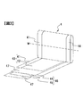
- FIG. 3 is a perspective view of the wound electrode group 4.
- the wound electrode group 4 has a laminated structure by winding the strip-like positive electrode 43 and the negative electrode 46 in a flat shape around the winding central axis W with the separator 47 interposed. ing.
- the positive electrode 43 has a strip-shaped positive electrode foil 41 and a positive electrode active material mixture layer 42 formed by coating a positive electrode active material mixture on both surfaces of the positive electrode foil 41.
- the negative electrode 46 has a negative electrode foil 44 and a negative electrode active material mixture layer 45 formed by coating a negative electrode active material mixture on both surfaces of the negative electrode foil 44.
- the positive electrode foil 41 is an aluminum foil having a thickness of about 20 ⁇ m
- the negative electrode foil 44 is a copper foil having a thickness of about 15 ⁇ m.
- the material of the separator 47 is a porous polyethylene resin.
- the laminated portion of the positive electrode 43 provided at one end is obtained by laminating the positive electrode uncoated portion where the positive electrode active material mixture layer 42 is not formed, that is, the exposed portion of the positive electrode foil 41.
- the laminated portion of the negative electrode 46 provided at the other end is obtained by laminating the uncoated portion of the negative electrode where the negative electrode active material mixture layer 45 is not formed, that is, the exposed portion of the negative electrode foil 44.
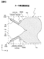
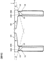
- FIG. 8 is a cross-sectional view taken along the line AA of FIG. 2, schematically showing the battery can 11 by a two-dot chain line.
- the negative electrode side also has the same configuration, so for convenience, reference numerals of constituent elements on the negative electrode side are also attached in parentheses.
- the laminated portion of the positive electrode 43 is crushed in advance, and as shown in FIG. 8, the thickness direction of the wound electrode group 4
- the two bundle electrode connection portions 48 are separated.
- the laminated portion of the negative electrode 46 is squeezed in advance, and as shown in FIG. It is separated into two bundle-like electrode connection parts 49 by being pushed and spread from the thickness direction center side of 4 toward the both wide surfaces 11 a of the battery can 11, that is, outward of the battery can 11.
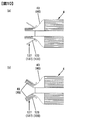
- FIG. 10 is a schematic plan view for explaining the step of forming a bundle electrode connection at the end of the wound electrode group 4.
- FIG. 10A is a schematic view showing a state in which the laminated portion of the positive electrode 43 in the wound electrode group 4 is inserted between a pair of bonding plates 127 provided on the positive electrode current collector 120 described later.
- FIG. 10B is a schematic view showing a state in which the laminated portion of the positive electrode 43 of the wound electrode group 4 inserted is separated from the inside and spread outward so as to be separated into two.
- the configuration on the positive electrode side is shown in FIG. 10, the configuration on the negative electrode side is also the same, so for convenience, reference numerals of constituent elements on the negative electrode side are also attached in parentheses.
- the laminated portion of the positive electrode 43 in the wound electrode group 4 is crushed and deformed in the thickness direction. Keep it. Thereafter, the stacked portion of the crushed positive electrode 43 is inserted between the pair of bonding plates 127, and the stacked portion of the positive electrode 43 is disposed inside the pair of main plates 123 constituting the pair of bonding plates 127.
- the laminated portion is separated into a pair of bundle electrode connection portions 48, and for bonding which can be inserted an ultrasonic oscillation horn between the pair of bundle electrode connection portions 48. Space is formed.
- the pair of bundle electrode connection portions 48 is inclined so as to spread outward, and an electrode bonding surface to be bonded to the positive electrode current collector 120 is provided on the outer surface.
- the laminated portion of the negative electrode 46 in the wound electrode group 4 is crushed in the thickness direction. Let it be deformed. Thereafter, the stacked portion of the crushed negative electrode 46 is inserted between the pair of bonding plates 137, and the stacked portion of the negative electrode 46 is disposed inside the pair of main plates 133 constituting the pair of bonding plates 137.
- the negative electrode current collector 130 After inserting the wound electrode group 4 between the pair of bonding plates 137 of the negative electrode current collector 130, as shown in FIG. 10 (b), the negative electrode current collector 130 is formed on the outer surface of the laminated portion of the negative electrode 46.
- the negative electrode 46 is spread in a V-shape from the inside to the outside so that the inner surface of the main plate 133 is in contact.
- the laminated portion is separated into a pair of bundle electrode connection portions 49, and for bonding which can be inserted an ultrasonic oscillation horn between the pair of bundle electrode connection portions 49. Space is formed.
- the pair of bundle electrode connection portions 49 is inclined so as to spread outward, and an electrode bonding surface to be bonded to the negative electrode current collector 130 is provided on the outer surface.
- the two separated bundle-like electrode connection portions 48 are main plates constituting the bonding plate 127 of the positive electrode current collector 120 on each of the wide sides 11 a side of the battery can 11. It is connected with 123 by ultrasonic bonding.
- the two separated bundle-like electrode connection parts 49 are connected by ultrasonic bonding to the main plate 133 that constitutes the bonding plate 137 of the negative electrode current collector 130 on each of the wide side 11a side of the battery can 11 It is done.
- FIG. 2 the direction of the winding central axis W (see FIG. 3) of the wound electrode group 4 is taken as the X direction, and the thickness direction of the wound electrode group 4 orthogonal to the X direction is taken as the Y direction.
- the height direction (vertical direction) of the wound electrode group 4 orthogonal to the Y direction is taken as the Z direction.
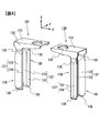
- FIG. 4 is a perspective view showing the positive electrode current collector 120 and the negative electrode current collector 130 of the secondary battery.
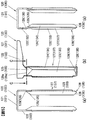
- 5 (a) is a left side view of the positive electrode current collector 120
- FIG. 5 (b) is a front view of the positive electrode current collector 120
- FIG. 5 (c) is a right side view of the positive electrode current collector 120.
- the positive electrode current collector 120 and the negative electrode current collector 130 are formed of the same material although they have different materials. Therefore, although FIG. 5 shows the configuration of the positive electrode current collector 120, for convenience, reference numerals of components of the negative electrode current collector 130 are also attached in parentheses.
- the positive electrode current collector 120 is bent and extended downward from the long side portion of the mounting plate 121 and the rectangular flat plate-like mounting plate 121 to which the positive electrode external terminal 14 is connected.
- a pair of connecting plates 122, and a drawn portion 128 extending from one end of the pair of connecting plates 122 toward the bottom surface 11c of the battery can 11 with a predetermined width.
- the negative electrode current collector 130 includes a rectangular flat plate-like mounting plate 131 to which the negative electrode external terminal 15 is connected, and a pair of connecting plates 132 bent and extended downward from the long side of the mounting plate 131.
- a drawn portion 138 extends from one end of the pair of connection plates 132 toward the bottom surface 11 c of the battery can 11 with a predetermined width.
- the attachment plates 121 and 131 are in contact with the inner surface of the battery lid 12 via an insulating material (not shown), and are disposed along the inner surface of the battery lid 12.
- the mounting plate 121 is provided with an opening for mounting the positive electrode external terminal 14, and the mounting plate 131 is provided with an opening for mounting the negative electrode external terminal 15.
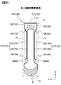
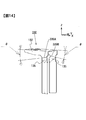
- FIG. 6 is a cross-sectional view taken along the line CC of FIG. 5 (b), schematically illustrating the battery can 11 by a two-dot chain line.
- FIG. 9 is a cross-sectional view taken along the line B--B of FIG. 2, and schematically shows the battery can 11 and the battery lid 12 by a two-dot chain line.
- FIG. 6 and FIG. 9 show the configuration on the positive electrode side, since the negative electrode side is also the same configuration, for convenience, reference numerals of constituent elements on the negative electrode side are also attached in parentheses.
- the pair of connection plates 122 of the positive electrode current collector 120 are bent substantially at right angles from the wide surface 11a side of the battery can 11 in the mounting plate 121 It extends along the both wide faces 11 a of the can 11 toward the bottom surface 11 c of the battery can 11 so as to cover the folded end of the wound electrode group 4.
- the pair of connection plates 132 of the negative electrode current collector 130 are bent substantially at right angles from the both wide surfaces 11 a of the battery can 11 in the mounting plate 131, and the battery cans 11 along the both wide surfaces 11 a of the battery can 11. It extends so as to cover the folded end of the wound electrode group 4 toward the bottom surface 11c of the second embodiment.
- each of the pair of drawn portions 128 of the positive electrode current collector 120 is from the wide surface 11 a side of the battery can 11 toward the center in the thickness direction of the wound electrode group 4. It is formed by the drawing process by a press so that it may protrude, and it is considered as the shape where the surface by the side of the wide surface 11a of the battery can 11 became depressed.
- each of the pair of drawn portions 138 of the negative electrode current collector 130 is drawn by a press so as to protrude from the wide surface 11 a side of the battery can 11 toward the center in the thickness direction of the wound electrode group 4. It is formed and the surface by the side of the wide surface 11a of the battery can 11 is made into the shape which became depressed.
- Each of the pair of drawn portions 128 of the positive electrode current collector 120 has a bonding plate 127, a bonding plate 125, and a reinforcing plate 126, as shown in FIG.
- the bonding plate 127 has an L-shaped cross section (see FIG. 8) by the main plate 123 extending in the z direction (the height direction of the wound electrode group 4) and the rib plate 124.
- the coupling plate 125 couples the connection plate 122, the main plate 123 and the rib plate 124.
- the reinforcing plate 126 couples the main plate 123 and the rib plate 124 at an end on the bottom surface 11 c side of the battery can 11. Similarly, as shown in FIG.
- each of the pair of drawn portions 138 of the negative electrode current collector 130 has a bonding plate 137, a bonding plate 135, and a reinforcing plate 136.
- the bonding plate 137 has an L-shaped cross section (see FIG. 8) by the main plate 133 extending in the z direction (the height direction of the wound electrode group 4) and the rib plate 134.
- the coupling plate 135 couples the connection plate 132, the main plate 133 and the rib plate 134.
- the reinforcing plate 136 couples the main plate 133 and the rib plate 134 at the end on the bottom surface 11 c side of the battery can 11.
- each of the pair of main plates 123 constituting the pair of bonding plates 127 of the positive electrode current collector 120 is the both wide surfaces of the battery can 11 in the two separated bundle electrode connection portions 48. It has a current collector bonding surface bonded to each electrode bonding surface on the side 11a.
- Each of the pair of rib plates 124 constituting the pair of bonding plates 127 of the positive electrode current collector 120 is a wide end portion of the main plate 123, which is an end portion on the center side of the wound electrode group 4. It is bent and extended toward the surface 11 a, that is, outward of the battery can 11.
- each of the pair of main plates 133 constituting the pair of bonding plates 137 of the negative electrode current collector 130 is of the battery can 11 in the two separated bundle electrode connection portions 49. It has a current collector bonding surface to be bonded to each of the electrode bonding surfaces on the both wide surfaces 11 a side.
- Each of the pair of rib plates 134 constituting the pair of bonding plates 137 of the negative electrode current collector 130 is a wide end portion of the main plate 133 which is an end portion on the center side of the wound electrode group 4. It is bent and extended toward the surface 11 a, that is, outward of the battery can 11.
- the rib plate 134 is in contact with the laminated portion of the negative electrode 46 in FIG. 8, it may not be in contact with it.
- the pair of main plates 123 of the positive electrode current collector 120 is closer to the center side of the wound electrode group 4 from the narrow side 11b side of the battery can 11 in the XY plane. It inclines so that the space
- the pair of rib plates 124 of the positive electrode current collector 120 is such that the distance between the rib plates 124 becomes wider from the narrow surface 11 b side of the battery can 11 toward the center side of the wound electrode group 4 in the XY plane. It is inclined to Similarly, as shown in FIGS.
- the pair of main plates 133 of the negative electrode current collector 130 is from the narrow side 11b side of the battery can 11 to the center side of the wound electrode group 4 in the XY plane. It inclines so that the space
- the pair of rib plates 134 of the negative electrode current collector 130 is such that the distance between the rib plates 134 becomes wider from the narrow side 11 b of the battery can 11 toward the center of the wound electrode group 4 in the XY plane. It is inclined to
- each of the pair of coupling plates 125 of the positive electrode current collector 120 is a wound electrode from one end on the bottom surface 11 c side of the battery can 11 in each of the pair of connection plates 122. It inclines toward the center in the thickness direction of the group 4 and extends toward the bottom surface 11 c of the battery can 11.
- Each of the pair of coupling plates 125 of the positive electrode current collector 120 is coupled to one end of each of the pair of bonding plates 127 on the battery lid 12 side.
- each of the pair of coupling plates 135 of the negative electrode current collector 130 is from one end on the bottom surface 11 c side of the battery can 11 in each of the pair of connection plates 132 It is inclined toward the center in the thickness direction of the wound electrode group 4 and extends toward the bottom surface 11 c of the battery can 11.
- Each of the pair of coupling plates 135 of the negative electrode current collector 130 is coupled to one end of each of the pair of bonding plates 137 on the battery lid 12 side.
- each of the pair of reinforcing plates 126 of the positive electrode current collector 120 is a wound electrode group from the end portion of the positive electrode current collector 120 on the bottom surface 11 c side of the battery can 11. It inclines toward the center in the thickness direction of 4 and extends toward the battery lid 12.
- Each of the pair of reinforcing plates 126 of the positive electrode current collector 120 is coupled to the end portion of the main plate 123 of the pair of bonding plates 127 and the rib plate 124 on the bottom surface 11 c side of the battery can 11.
- the coupling plate 125 of the positive electrode current collector 120 includes a substantially triangular coupling surface 125F having a first bending side 129a, a second bending side 129b, and a third bending side 129c.
- the coupling plate 125 of the positive electrode current collector 120 is continuous with one end of the connection plate 122 at a first bending side 129a, is continuous with the main plate 123 of the bonding plate 127 at a second bending side 129b, and is a bonding plate at a third bending side 129c. It is continuous with the rib plate 124 of 127.
- the coupling plate 135 of the negative electrode current collector 130 includes a substantially triangular coupling surface 135F having a first bending side 139a, a second bending side 139b, and a third bending side 139c.
- the bonding plate 135 of the negative electrode current collector 130 is continuous with one end of the connection plate 132 at the first bending side 139a, is continuous with the main plate 133 of the bonding plate 137 at the second bending side 139b, and is the bonding plate at the third bending side 139c. It is continuous with the rib plate 134 of 137.
- the boundary between the main plate 123 and the rib plate 124 on the coupling surface 125F side of the positive electrode current collector 120 is a fourth bending side 129d, and the main plate 123 and the rib plate 124 are continuous at the fourth bending side 129d.
- the boundary between the main plate 133 on the side of the coupling surface 135F of the negative electrode current collector 130 and the rib plate 134 is the fourth bending side 139d, and the main plate 133 and the rib plate 134 are continuous at the fourth bending side 139d.
- the first bent side 129a of the positive electrode current collector 120 is provided in the X direction, that is, parallel to the winding central axis direction.
- Each of the second bending side 129b, the third bending side 129c, and the fourth bending side 129d in the positive electrode current collector 120 is separated from the connection plate 122 by a predetermined distance L1 toward the center of the wound electrode group 4 in the thickness direction,
- the connection plate 122 intersects the bottom surface 11c of the battery can 11 at a point PP1 separated by a predetermined distance B1.
- the second bending side 129b, the third bending side 129c, and the fourth bending side 129d have a Y-shape in a side view.
- the first bending side 139a of the negative electrode current collector 130 is provided in the X direction, that is, parallel to the winding central axis direction.
- Each of the second bending side 139b, the third bending side 139c, and the fourth bending side 139d in the negative electrode current collector 130 is separated from the connection plate 132 by a predetermined distance L1 toward the center in the thickness direction of the wound electrode group 4;
- the connection plate 132 intersects with the bottom surface 11c of the battery can 11 at a point NP1 separated by a predetermined distance B1.
- the second bending side 139b, the third bending side 139c, and the fourth bending side 139d have a Y-shape in a side view.
- the reinforcing plate 126 of the positive electrode current collector 120 has a triangular reinforcing surface 126F having a fifth bending side 129e and a sixth bending side 129f, and an edge connecting the fifth bending side 129e and the sixth bending side 129f.
- the reinforcing plate 126 of the positive electrode current collector 120 is continuous with the main plate 123 of the bonding plate 127 at the fifth bending side 129e and is continuous with the rib plate 124 of the bonding plate 127 at the sixth bending side 129f.
- the reinforcing plate 136 of the negative electrode current collector 130 is a triangular reinforcing member having a fifth bending side 139e and a sixth bending side 139f, and an edge connecting the fifth bending side 139e and the sixth bending side 139f. It has a surface 136F.
- the reinforcing plate 136 of the negative electrode current collector 130 is continuous with the main plate 133 of the bonding plate 137 at the fifth bending side 139 e and is continuous with the rib plate 134 of the bonding plate 137 at the sixth bending side 139 f.
- Each of the fifth bending side 129e, the sixth bending side 129f, and the fourth bending side 129d of the positive electrode current collector 120 is separated from the connection plate 122 by a predetermined distance L1 toward the center of the wound electrode group 4 in the thickness direction,
- the end of the positive electrode current collector 120 on the battery can bottom 11 c side intersects with the battery lid 12 at a point PP 2 separated by a predetermined distance B 2.
- the fifth bending side 129e, the sixth bending side 129f, and the fourth bending side 129d have an inverted Y shape in a side view.
- each of the fifth bending side 139e, the sixth bending side 139f, and the fourth bending side 139d of the negative electrode current collector 130 is separated from the connection plate 132 by a predetermined distance L1 toward the center of the wound electrode group 4 in the thickness direction.
- the end of the negative electrode current collector 130 on the battery can bottom surface 11 c side intersects with the battery lid 12 at a point NP 2 separated by a predetermined distance B 2.
- the fifth bending side 139e, the sixth bending side 139f, and the fourth bending side 139d have an inverted Y shape in a side view.
- a pair of connecting plates 125 are provided to connect each of the pair of connecting plates 122 extending from the mounting plate 121 along the inner surface of the housing 11 to the bottom surface 11 c of the battery can 11.
- the positive electrode current collector 120 Since the junction plate 127 and the connection plate 122 are three-dimensionally coupled by the coupling plate 125, the positive electrode current collector 120 has improved rigidity against vibration and impact in the X, Y, and Z directions, and vibration applied to the secondary battery It is possible to prevent the deformation of the positive electrode current collector 120 due to shock or impact.
- a pair of connecting plates 135 are provided to connect each of the pair of connecting plates 132 extending from the mounting plate 131 along the inner surface of the housing to the bottom surface 11 c of the battery can 11. Since the bonding plate 137 and the connection plate 132 are three-dimensionally connected by the bonding plate 135, the rigidity of the negative electrode current collector 130 against vibration and impact in the X, Y, and Z directions is improved, and the vibration applied to the secondary battery And deformation of the negative electrode current collector 130 caused by impact can be prevented.
- the drawn portion 128 consisting of the connecting plate 125, the main plate 123, the rib plate 124 and the reinforcing plate 126 can be integrally formed by drawing with a press, so the positive electrode current collector 120 can be manufactured at low cost. It can be manufactured.
- the drawn portion 138 consisting of the coupling plate 135, the main plate 133, the rib plate 134 and the reinforcing plate 136 can be integrally formed by drawing with a press, the negative electrode current collector 130 can be manufactured at low cost. It can be manufactured.
- FIGS. 11 and 12 A secondary battery according to a second embodiment will be described with reference to FIGS. 11 and 12.
- the same or corresponding parts as in the first embodiment are designated by the same reference numerals, and the description will be omitted.
- the difference from the first embodiment will be described in detail.
- FIG. 11 is a perspective view showing a positive electrode current collector 220 and a negative electrode current collector 230 of a secondary battery according to a second embodiment of the present invention
- FIG. 12 relates to the second embodiment of the present invention
- FIG. 10 is a side cross-sectional view showing the positive electrode current collector 220 of the secondary battery and the wound electrode group 4, and corresponds to FIG. 9.
- FIG. 12 shows the configuration of the positive electrode current collector 220, for convenience, reference numerals of components of the negative electrode current collector 230 are also attached in parentheses.
- the same effect as that of the first embodiment can be obtained. Furthermore, in the second embodiment, since it is not necessary to form the reinforcing plates 126 and 136, it is possible to manufacture the positive electrode current collector 220 and the negative electrode current collector 230 at low cost as compared with the first embodiment. it can. Thereby, the cost of the secondary battery can be reduced.
- the mass of the wound electrode group 4 is smaller than that of the first embodiment, and the main plates 123 and 133, the rib plates 124 and 134, and the connection plate 122 are formed by the coupling plates 125 and 135, respectively. , 132 are useful when sufficient rigidity can be obtained by combining them.
- FIG. 13 is a perspective view showing a positive electrode current collector 320 of a secondary battery according to a third embodiment of the present invention
- FIG. 14 is a perspective view showing a negative electrode current collector 330.
- FIG. 15 is a side view of the positive electrode current collector 320 of FIG. 13 and the negative electrode current collector 330 of FIG.
- the same or corresponding parts as in the first and second embodiments are designated by the same reference numerals, and the description will be omitted.
- the difference from the second embodiment will be described in detail.
- each of the first bending sides 329A, 329B, 339A, 339B is a predetermined X direction which is a winding central axis direction of the winding electrode group 4. It is provided to make an angle ⁇ .
- the pair of first bending sides 329A and 329B in each of the pair of coupling plates 125 provided on the positive electrode current collector 320 are the coupling plate 125 and the connection plate 122 on the left side as viewed in the drawing.
- the first bending side 329B which is the boundary between the coupling plate 125 and the connection plate 122 on the right side in the drawing, point Q1 in side view as shown in FIG. are provided to cross each other.
- the pair of first bent sides 339A and 339B in each of the pair of coupling plates 135 provided on the negative electrode current collector 330 is connected to the coupling plate 135 on the left side in the drawing sheet.
- a first bending side 339A which is a boundary with the plate 132, and a first bending side 339B which is a boundary between the coupling plate 135 and the connection plate 132 on the right side in the drawing, as shown in FIG. are provided so as to intersect at point Q2.
- the same effect as that of the second embodiment can be obtained. Furthermore, in the third embodiment, the rigidity against vibration or impact in the Y direction is enhanced as compared to the second embodiment in which the pair of first bending sides are provided parallel to the X direction. it can.
- the coupling plate 425 of the positive electrode current collector 420 has a substantially trapezoidal coupling surface 425F and integrally couples the main plate 423, the rib plate 424, the bottom plate 427a, and the connection plate 122.
- the reinforcing plate 426 of the positive electrode current collector 420 has a trapezoidal reinforcing surface 426 F, and at the end of the positive electrode current collector 420 on the bottom surface 11 c side of the battery can 11, the main plate 423, the rib plate 424 and the bottom plate 427 a It is connected.
- the coupling plate 435 of the negative electrode current collector 430 has a substantially trapezoidal coupling surface 435 F and integrally couples the main plate 433, the rib plate 434, the bottom plate 437 a, and the connection plate 132.
- the reinforcing plate 436 of the negative electrode current collector 430 has a trapezoidal reinforcing surface 436 F, and at the end of the negative electrode current collector 430 on the bottom surface 11 c side of the battery can 11, the main plate 433, the rib plate 434 and the bottom plate 437 a It is connected.
- the coupling plate 535 of the negative electrode current collector 530 is provided with a coupling surface 535F having a linear first bending side 139a and a curved bending side 539g.
- the reinforcing plate 536 of the negative electrode current collector 530 is provided with a reinforcing surface 536F having an edge on the bottom surface 11c side of the battery can 11 and a curved bending edge 539h.
- the material of the positive electrode external terminal, the positive electrode current collector and the positive electrode foil is not limited to aluminum, and may be an aluminum alloy.
- the material of the negative electrode external terminal, the negative electrode current collector and the negative electrode foil is not limited to copper, and may be a copper alloy.
Abstract
A secondary battery comprises a wound electrode group, a battery can, a battery cap, external terminals provided on the battery cap, and collectors connecting the wound electrode group and the external terminals. The stacked portion of an electrode constituting the wound electrode group is divided from the side of the thickness direction center of the wound electrode group toward the exterior of the battery can into two bundle electrode connection portions. The collectors each comprises: bonding plates having main plates bonded to the bundle electrode connection portions and rib plates bent and extending from the main plates toward the exterior of the battery can; an attaching plate being along the inner surface of the battery cap; connecting plates bent from the side portions of the attaching plate and extending toward the bottom of the battery can; and joining plates for joining the connecting plates and the bonding plates. The joining plates slope from one battery can bottom side ends of the connecting plates toward the thickness direction center of the wound electrode group and extend toward the bottom of the battery can. The joining plates join one battery cap side ends of the bonding plates.
Description
本発明は、ハイブリッド型の電気自動車や純粋な電気自動車等の車両に搭載される二次電池に関する。
The present invention relates to a secondary battery mounted in a vehicle such as a hybrid electric vehicle or a pure electric vehicle.
正極箔に正極活物質合剤が塗工された正極電極および負極箔に負極活物質合剤が塗工された負極電極をセパレータを介して捲回した扁平形電極群と、電解液とを角形の電池容器内に収容し、扁平形電極群と電気的に接続された外部端子を設けた角形二次電池が車両駆動用電池として広く知られている(特許文献1参照)。
A flat electrode group obtained by winding a negative electrode, in which a positive electrode active material mixture is coated on a positive electrode foil and a negative electrode on which a negative electrode active material mixture is coated on a negative electrode foil, through a separator A rectangular secondary battery which is accommodated in the battery case of the above and provided with an external terminal electrically connected to the flat electrode group is widely known as a vehicle drive battery (see Patent Document 1).
扁平形電極群の捲回中心軸方向の一端部には、正極活物質合剤が塗工されることなく正極箔が露出した正極未塗工部が積層され、扁平形電極群の捲回中心軸方向の他端部には、負極活物質合剤が塗工されることなく負極箔が露出した負極未塗工部が積層されている。
A positive electrode uncoated portion, in which the positive electrode foil is exposed without being coated with the positive electrode active material mixture, is laminated at one end in the winding central axis direction of the flat electrode group, and the winding center of the flat electrode group On the other end in the axial direction, a negative electrode uncoated portion in which the negative electrode foil is exposed without being coated with the negative electrode active material mixture is laminated.
特許文献1では、扁平形電極群の内部に断面略V字状の集電体を挿入し、扁平形電極群の未塗工部の積層部分を2つに分けて束ねた上で、それぞれの束を集電体に接続する構造が提案されている。
In Patent Document 1, a current collector having a substantially V-shaped cross section is inserted into the flat electrode group, and the laminated portion of the uncoated portion of the flat electrode group is divided into two and bundled. A structure has been proposed to connect the bundle to the current collector.
車両に搭載される二次電池には振動や衝撃が作用するため、電極群を保持する集電体の変形を防止する必要がある。
Since vibrations and shocks act on the secondary battery mounted on the vehicle, it is necessary to prevent deformation of the current collector holding the electrode group.
上記特許文献1に記載の角形電池では、正極集電体は、一方の接合板部の一端部から接続片が立ち上げ形成され、この接続片が外部端子に接続されているリード板の一端部から垂下された接続片にスポット溶接にて接合されている。負極集電体は、一方の接合板部の一端部から他方の接合板部に向けて折曲されるとともに一端外方に向けて長く延びる接続片が突出形成され、この接続片がリード板に接続されている。このリード板は、ケース内面に沿って配設され、その上下端からL字状に接続部が折り曲げ形成され、上端の接続部が負極外部端子を構成する封口板にスポット溶接等にて接合され、下端の接続部が負極集電体の接続片にスポット溶接等にて接合されている。
In the prismatic battery described in Patent Document 1, the positive electrode current collector is formed by raising a connection piece from one end of one of the bonding plates, and one end of a lead plate in which the connection piece is connected to an external terminal. Is joined by spot welding to the connection piece suspended from the bottom. The negative electrode current collector is bent from one end of one bonding plate to the other bonding plate, and a connecting piece extending long outwardly is formed so as to protrude from the one end, and this connecting piece forms a lead plate. It is connected. The lead plate is disposed along the inner surface of the case, and the L-shaped connecting portion is bent from the upper and lower ends thereof, and the connecting portion at the upper end is joined by spot welding or the like to the sealing plate constituting the negative electrode external terminal. The lower end connection portion is joined to the connection piece of the negative electrode current collector by spot welding or the like.
特許文献1に記載の角形電池では、集電体の一対の接合板部同士とリード板とが一体的に結合されていないため、振動、衝撃が加わった際に、集電体やリード板が変形するおそれがあった。
In the prismatic battery described in Patent Document 1, since the pair of joining plate portions of the current collector and the lead plate are not integrally coupled, the current collector and the lead plate are subjected to vibration and impact. There was a risk of deformation.
電極群は、集電体に接合されて電池容器内で保持されているため、電極群の質量が大きいほど、集電体が変形する可能性は高くなる。車両に搭載される二次電池は、大容量化が求められており、電極群の質量は増加傾向にあるため、集電体の剛性の向上が要望されている。
Since the electrode group is joined to the current collector and held in the battery case, the larger the mass of the electrode group, the higher the possibility of deformation of the current collector. Since the secondary battery mounted on a vehicle is required to have a large capacity, and the mass of the electrode group tends to increase, there is a demand for improvement in the rigidity of the current collector.
本発明の第1の態様による二次電池は、正極電極および負極電極をセパレータを介在させて捲回した扁平形電極群と、扁平形電極群を収容する電池缶と、電池缶を封止する電池蓋と、電池蓋に設けられた正極外部端子および負極外部端子と、正極電極と正極外部端子とを接続する正極集電体と、負極電極と負極外部端子とを接続する負極集電体とを備え、扁平形電極群の捲回中心軸方向両端部において、正極電極および負極電極の積層部のそれぞれは、扁平形電極群の厚み方向中心側から電池缶の外方に向かって2つの束状電極接続部に分離され、正極集電体および負極集電体のそれぞれは、分離した2つの束状電極接続部に設けられた電極接合面に接合される集電体接合面を有する主板と、主板から電池缶の外方に向かって屈曲して延在するリブ板とを有する一対の接合板と、電池蓋の内面に沿う取付板と、取付板の側部から屈曲して電池缶の底面に向かって延在する一対の接続板と、一対の接続板のそれぞれと、一対の接合板のそれぞれとを結合する一対の結合板とを備え、一対の結合板のそれぞれは、一対の接続板のそれぞれにおける電池缶底面側の一端から、扁平形電極群の厚み方向中心に向かうように傾斜しつつ、かつ、電池缶の底面に向かって延在し、一対の接合板のそれぞれにおける電池蓋側の一端と結合されている。
本発明の第2の態様によると、第1の態様の二次電池において、結合板は、3つの屈曲辺を有する結合面を備え、第1屈曲辺で接続板の一端と連続し、第2屈曲辺および第3屈曲辺で接合板の主板およびリブ板のそれぞれと連続していることが好ましい。
本発明の第3の態様によると、第2の態様の二次電池において、結合面側の主板とリブ板との境界は、第4屈曲辺とされ、第2、第3および第4屈曲辺のそれぞれが、接続板から扁平形電極群の厚み方向中心側に所定距離だけ離れ、かつ、接続板の一端から電池缶の底面側に所定距離だけ離れた点で交差し、第2、第3および第4屈曲辺によって側面視でY字状を呈していることが好ましい。
本発明の第4の態様によると、第2または3の態様の二次電池において、第1屈曲辺は、扁平形電極群の捲回中心軸方向と所定角度をなすように設けられ、正極集電体および負極集電体のそれぞれに設けられる一対の結合板のそれぞれにおける第1屈曲辺は、一対の結合板のそれぞれにおける第1屈曲辺同士が側面視で交差するように設けられていることが好ましい。
本発明の第5の態様によると、第1ないし4のいずれか1の態様の二次電池において、正極集電体および負極集電体における電池缶の底面側の端部に、主板とリブ板とを結合する補強板が設けられていることが好ましい。
本発明の第6の態様によると、第1ないし5のいずれか1の態様の二次電池において、正極集電体は、接続板の他端側で正極外部端子と接続され、負極集電体は、接続板の他端側で負極外部端子と接続されていることが好ましい。 The secondary battery according to the first aspect of the present invention seals a flat electrode group in which a positive electrode and a negative electrode are wound with a separator interposed, a battery can containing the flat electrode group, and a battery can. Battery cover, positive electrode external terminal and negative electrode external terminal provided on battery cover, positive electrode current collector connecting positive electrode and positive electrode external terminal, negative electrode current collector connecting negative electrode and negative electrode external terminal In each of the winding central axis direction both ends of the flat electrode group, each of the laminated portions of the positive electrode and the negative electrode is a bundle of two toward the outside of the battery can from the center side in the thickness direction of the flat electrode group. A main plate having a current collector bonding surface separated into a strip electrode connection portion, and each of a positive electrode current collector and a negative electrode current collector being joined to an electrode bonding surface provided in two separate bundle electrode connection portions Extend from the main plate to the outside of the battery can A pair of connecting plates having a rib plate, a mounting plate along the inner surface of the battery lid, a pair of connecting plates bent from the side of the mounting plate and extending toward the bottom of the battery can, and a pair of connecting plates , And a pair of connecting plates for connecting each of the pair of bonding plates, each of the pair of connecting plates is a flat electrode group from one end of the bottom of the battery can in each of the pair of connecting plates. It inclines toward the center in the thickness direction, extends toward the bottom of the battery can, and is coupled to one end on the battery lid side of each of the pair of bonding plates.
According to a second aspect of the present invention, in the secondary battery of the first aspect, the coupling plate includes a coupling surface having three bending sides, and is continuous with one end of the connecting plate at the first bending side, the second It is preferable to be continuous with each of the main plate and the rib plate of the joint plate at the bending side and the third bending side.
According to a third aspect of the present invention, in the secondary battery of the second aspect, the boundary between the main plate on the coupling surface side and the rib plate is a fourth bending side, and the second, third and fourth bending sides Are each separated by a predetermined distance from the connection plate to the center side in the thickness direction of the flat electrode group and from the one end of the connection plate to the bottom side of the battery can by a predetermined distance. It is preferable that it has a Y-shape in a side view by the fourth bending side.
According to the fourth aspect of the present invention, in the secondary battery of the second or third aspect, the first bent side is provided to form a predetermined angle with the winding central axis direction of the flat electrode group, and the positive electrode collection The first bending side of each of the pair of coupling plates provided on each of the current collector and the negative electrode current collector is provided such that the first bending sides of each of the pair of coupling plates cross each other in side view Is preferred.
According to a fifth aspect of the present invention, in the secondary battery of any one of the first to fourth aspects, the main plate and the rib plate are provided on the end of the positive electrode current collector and the negative electrode current collector on the bottom side of the battery can. Preferably, a reinforcing plate is provided to connect the two.
According to a sixth aspect of the present invention, in the secondary battery of any one of the first to fifth aspects, the positive electrode current collector is connected to the positive electrode external terminal at the other end of the connection plate, and the negative electrode current collector Is preferably connected to the negative electrode external terminal at the other end of the connection plate.
本発明によれば、二次電池に加わる振動や衝撃を起因とした集電体の変形を防止し、耐振性、耐衝撃性に優れた二次電池を提供することができる。
According to the present invention, it is possible to provide a secondary battery excellent in vibration resistance and impact resistance by preventing deformation of the current collector caused by vibration or impact applied to the secondary battery.
以下、本発明による二次電池を角形リチウムイオン電池に適用した実施の形態を図面を参照して説明する。
―第1の実施の形態―
図1は、二次電池の外観斜視図である。図2は、二次電池の構成を示す分解斜視図である。なお、図2ではガス排出弁16および注液部17の図示は省略している。 Hereinafter, an embodiment in which a secondary battery according to the present invention is applied to a prismatic lithium ion battery will be described with reference to the drawings.
-First embodiment-
FIG. 1 is an external perspective view of a secondary battery. FIG. 2 is an exploded perspective view showing the configuration of the secondary battery. In addition, illustration of thegas discharge valve 16 and the liquid injection part 17 is abbreviate | omitted in FIG.
―第1の実施の形態―
図1は、二次電池の外観斜視図である。図2は、二次電池の構成を示す分解斜視図である。なお、図2ではガス排出弁16および注液部17の図示は省略している。 Hereinafter, an embodiment in which a secondary battery according to the present invention is applied to a prismatic lithium ion battery will be described with reference to the drawings.
-First embodiment-
FIG. 1 is an external perspective view of a secondary battery. FIG. 2 is an exploded perspective view showing the configuration of the secondary battery. In addition, illustration of the
[電池容器]
図1に示すように、二次電池は電池缶11と電池蓋12とからなる角形で薄形の電池容器を備える。図2に示すように、電池缶11は、捲回電極群4を収容するものであり、一対の幅広面11aと一対の幅狭面11bと底面11cとを有し、上面が開口とされた矩形箱状に形成されている。捲回電極群4は、電池缶11に収容される前に、電池蓋12に接続された正極集電体120および負極集電体130に超音波接合等により接合されている。 [Battery container]
As shown in FIG. 1, the secondary battery is provided with a rectangular thin battery container including a battery can 11 and abattery lid 12. As shown in FIG. 2, the battery can 11 accommodates the wound electrode group 4 and has a pair of wide surfaces 11a, a pair of narrow surfaces 11b and a bottom surface 11c, and the upper surface is open. It is formed in a rectangular box shape. Before being accommodated in the battery can 11, the wound electrode group 4 is joined to the positive electrode current collector 120 and the negative electrode current collector 130 connected to the battery lid 12 by ultrasonic bonding or the like.
図1に示すように、二次電池は電池缶11と電池蓋12とからなる角形で薄形の電池容器を備える。図2に示すように、電池缶11は、捲回電極群4を収容するものであり、一対の幅広面11aと一対の幅狭面11bと底面11cとを有し、上面が開口とされた矩形箱状に形成されている。捲回電極群4は、電池缶11に収容される前に、電池蓋12に接続された正極集電体120および負極集電体130に超音波接合等により接合されている。 [Battery container]
As shown in FIG. 1, the secondary battery is provided with a rectangular thin battery container including a battery can 11 and a
捲回電極群4は、袋状の絶縁シート13で覆われた状態で電池缶11に収容されている。これにより、電池缶11の底面および側面と、捲回電極群4とは電気的に絶縁されている。電池蓋12は、矩形平板状であって、電池缶11の開口を塞ぐように溶接され、電池缶11を封止している。
The wound electrode group 4 is accommodated in the battery can 11 in a state of being covered with the bag-like insulating sheet 13. Thereby, the bottom and side surfaces of the battery can 11 and the wound electrode group 4 are electrically insulated. The battery cover 12 has a rectangular flat plate shape and is welded so as to close the opening of the battery can 11 and seals the battery can 11.
[注液部およびガス排出弁]
図1に示すように、電池蓋12には、注液部17が設けられている。注液部17には、電池容器内に電解液を注入するための注液孔が穿設されている。注液孔は、電解液注入後に注液栓によって封止される。電池蓋12には、ガス排出弁16も設けられている。ガス排出弁16は、プレス加工によって電池蓋12を部分的に薄肉化することで形成されている。ガス排出弁16は、二次電池が過充電等の異常により発熱してガスが発生し、電池容器内の圧力が上昇して所定圧力に達したときに開裂して、内部からガスを排出することで電池容器内の圧力を低減させる。 [Injection part and gas discharge valve]
As shown in FIG. 1, theliquid injection part 17 is provided on the battery cover 12. A liquid injection hole for injecting an electrolytic solution into the battery container is bored in the liquid injection portion 17. The injection hole is sealed by the injection valve after the injection of the electrolyte. The battery cover 12 is also provided with a gas discharge valve 16. The gas discharge valve 16 is formed by partially thinning the battery cover 12 by press processing. The gas discharge valve 16 generates heat by generating heat due to an abnormality such as overcharging of the secondary battery, and when the pressure in the battery container rises and reaches a predetermined pressure, it is cleaved to discharge the gas from the inside Thereby reducing the pressure in the battery container.
図1に示すように、電池蓋12には、注液部17が設けられている。注液部17には、電池容器内に電解液を注入するための注液孔が穿設されている。注液孔は、電解液注入後に注液栓によって封止される。電池蓋12には、ガス排出弁16も設けられている。ガス排出弁16は、プレス加工によって電池蓋12を部分的に薄肉化することで形成されている。ガス排出弁16は、二次電池が過充電等の異常により発熱してガスが発生し、電池容器内の圧力が上昇して所定圧力に達したときに開裂して、内部からガスを排出することで電池容器内の圧力を低減させる。 [Injection part and gas discharge valve]
As shown in FIG. 1, the
[外部端子]
図1および図2に示すように、電池蓋12には、正極外部端子14および負極外部端子15が設けられている。図2に示すように、正極外部端子14および負極外部端子15は、それぞれ電池缶11内に配設される正極集電体120および負極集電体130にかしめにより接続されている。正極外部端子14、正極集電体120、負極外部端子15および負極集電体130は、それぞれ図示しない絶縁材によって電池蓋12と電気的に絶縁されている。 [External terminal]
As shown in FIGS. 1 and 2, thebattery cover 12 is provided with a positive electrode external terminal 14 and a negative electrode external terminal 15. As shown in FIG. 2, the positive electrode external terminal 14 and the negative electrode external terminal 15 are connected by caulking to the positive electrode current collector 120 and the negative electrode current collector 130 disposed in the battery can 11, respectively. The positive electrode external terminal 14, the positive electrode current collector 120, the negative electrode external terminal 15, and the negative electrode current collector 130 are each electrically insulated from the battery lid 12 by an insulating material (not shown).
図1および図2に示すように、電池蓋12には、正極外部端子14および負極外部端子15が設けられている。図2に示すように、正極外部端子14および負極外部端子15は、それぞれ電池缶11内に配設される正極集電体120および負極集電体130にかしめにより接続されている。正極外部端子14、正極集電体120、負極外部端子15および負極集電体130は、それぞれ図示しない絶縁材によって電池蓋12と電気的に絶縁されている。 [External terminal]
As shown in FIGS. 1 and 2, the
正極外部端子14および正極集電体120は、いずれもアルミニウムにより形成され、負極外部端子15および負極集電体130は、いずれも銅により形成されている。正極集電体120および負極集電体130は、それぞれ捲回電極群4の正極電極43および負極電極46に接合されている。
The positive electrode external terminal 14 and the positive electrode current collector 120 are both formed of aluminum, and the negative electrode external terminal 15 and the negative electrode current collector 130 are both formed of copper. The positive electrode current collector 120 and the negative electrode current collector 130 are respectively joined to the positive electrode 43 and the negative electrode 46 of the wound electrode group 4.
正極外部端子14が正極集電体120を介して捲回電極群4の正極電極43に電気的に接続され、負極外部端子15が負極集電体130を介して捲回電極群4の負極電極46に電気的に接続されている。このため、正極外部端子14および負極外部端子15を介して外部負荷に電力が供給され、あるいは、正極外部端子14および負極外部端子15を介して外部発電電力が捲回電極群4に供給されて充電される。
The positive electrode external terminal 14 is electrically connected to the positive electrode 43 of the wound electrode group 4 through the positive electrode current collector 120, and the negative electrode external terminal 15 is the negative electrode of the wound electrode group 4 through the negative electrode current collector 130. It is electrically connected to 46. Therefore, power is supplied to the external load through the positive electrode external terminal 14 and the negative electrode external terminal 15, or externally generated power is supplied to the wound electrode group 4 through the positive electrode external terminal 14 and the negative electrode external terminal 15. Be charged.
図示しないが、複数の二次電池が並置されて、隣接する二次電池の正極外部端子14と負極外部端子15とが金属製の板材からなるバスバーによって電気的に接続されることで、複数の二次電池からなる組電池が形成される。正極外部端子14および負極外部端子15において電池容器の外に露出している部分には、それぞれおねじが形成されており、バスバーはナットによって正極外部端子14および負極外部端子15に締結される。
Although not shown, a plurality of secondary batteries are juxtaposed, and the positive and negative external terminals 14 and 15 of the adjacent secondary batteries are electrically connected by a bus bar made of a metal plate, whereby the plurality of secondary batteries are electrically connected. An assembled battery composed of a secondary battery is formed. An external thread is formed on each of the positive electrode external terminal 14 and the negative electrode external terminal 15 exposed to the outside of the battery case, and the bus bar is fastened to the positive electrode external terminal 14 and the negative electrode external terminal 15 by a nut.
[捲回電極群]
図3を参照して、捲回電極群4について説明する。図3は捲回電極群4の斜視図である。図3に示すように、捲回電極群4は、帯状の正極電極43および負極電極46をセパレータ47を介在させて、捲回中心軸W周りに扁平形状に捲回することで積層構造とされている。 [Wound electrode group]
Thewound electrode group 4 will be described with reference to FIG. FIG. 3 is a perspective view of the wound electrode group 4. As shown in FIG. 3, the wound electrode group 4 has a laminated structure by winding the strip-like positive electrode 43 and the negative electrode 46 in a flat shape around the winding central axis W with the separator 47 interposed. ing.
図3を参照して、捲回電極群4について説明する。図3は捲回電極群4の斜視図である。図3に示すように、捲回電極群4は、帯状の正極電極43および負極電極46をセパレータ47を介在させて、捲回中心軸W周りに扁平形状に捲回することで積層構造とされている。 [Wound electrode group]
The
正極電極43は、帯状の正極箔41と、正極箔41の両面に正極活物質合剤が塗工されて形成される正極活物質合剤層42とを有する。負極電極46は、負極箔44と、負極箔44の両面に負極活物質合剤が塗工されて形成される負極活物質合剤層45とを有する。正極箔41は、厚さ20μm程度のアルミニウム箔であり、負極箔44は、厚さ15μm程度の銅箔である。セパレータ47の素材は多孔質のポリエチレン樹脂である。
The positive electrode 43 has a strip-shaped positive electrode foil 41 and a positive electrode active material mixture layer 42 formed by coating a positive electrode active material mixture on both surfaces of the positive electrode foil 41. The negative electrode 46 has a negative electrode foil 44 and a negative electrode active material mixture layer 45 formed by coating a negative electrode active material mixture on both surfaces of the negative electrode foil 44. The positive electrode foil 41 is an aluminum foil having a thickness of about 20 μm, and the negative electrode foil 44 is a copper foil having a thickness of about 15 μm. The material of the separator 47 is a porous polyethylene resin.
捲回電極群4の捲回中心軸Wの方向、すなわち捲回方向に直交する方向の両端部は、一方が正極電極43の積層部とされ、他方が負極電極46の積層部とされている。一端に設けられる正極電極43の積層部は、正極活物質合剤層42が形成されていない正極未塗工部、すなわち正極箔41の露出部が積層されたものである。他端に設けられる負極電極46の積層部は、負極活物質合剤層45が形成されていない負極未塗工部、すなわち負極箔44の露出部が積層されたものである。
One of the two ends of the direction of the winding central axis W of the wound electrode group 4, that is, in the direction orthogonal to the winding direction, is a stacked portion of the positive electrode 43 and the other is a stacked portion of the negative electrode 46. . The laminated portion of the positive electrode 43 provided at one end is obtained by laminating the positive electrode uncoated portion where the positive electrode active material mixture layer 42 is not formed, that is, the exposed portion of the positive electrode foil 41. The laminated portion of the negative electrode 46 provided at the other end is obtained by laminating the uncoated portion of the negative electrode where the negative electrode active material mixture layer 45 is not formed, that is, the exposed portion of the negative electrode foil 44.
図8は図2のA-A線切断断面図であり、模式的に電池缶11を二点鎖線で図示している。図8では正極側の構成を示しているが、負極側も同様の構成であるため、便宜上、かっこ書きで負極側の構成要素の参照番号も付している。図3に示した捲回電極群4の捲回中心軸W方向の一端部において、正極電極43の積層部は、予め押し潰され、図8に示すように、捲回電極群4の厚み方向中心側から電池缶11の両幅広面11a側に向かって、すなわち電池缶11の外方に向かって押し広げられることで2つの束状電極接続部48に分離されている。同様に、図3に示した捲回電極群4の捲回中心軸W方向の他端部において、負極電極46の積層部は、予め押し潰され、図8に示すように、捲回電極群4の厚み方向中心側から電池缶11の両幅広面11a側に向かって、すなわち電池缶11の外方に向かって押し広げられることで2つの束状電極接続部49に分離されている。
FIG. 8 is a cross-sectional view taken along the line AA of FIG. 2, schematically showing the battery can 11 by a two-dot chain line. Although the configuration on the positive electrode side is shown in FIG. 8, the negative electrode side also has the same configuration, so for convenience, reference numerals of constituent elements on the negative electrode side are also attached in parentheses. At one end in the winding central axis W direction of the wound electrode group 4 shown in FIG. 3, the laminated portion of the positive electrode 43 is crushed in advance, and as shown in FIG. 8, the thickness direction of the wound electrode group 4 By being spread from the center side toward the both wide surfaces 11 a of the battery can 11, that is, outward of the battery can 11, the two bundle electrode connection portions 48 are separated. Similarly, at the other end of the wound electrode group 4 shown in FIG. 3 in the winding central axis W direction, the laminated portion of the negative electrode 46 is squeezed in advance, and as shown in FIG. It is separated into two bundle-like electrode connection parts 49 by being pushed and spread from the thickness direction center side of 4 toward the both wide surfaces 11 a of the battery can 11, that is, outward of the battery can 11.
捲回電極群4の束状電極接続部48,49は、以下のようにして形成される。図10は、捲回電極群4の端部において、束状電極接続部を形成する工程を説明する平面模式図である。図10(a)は捲回電極群4における正極電極43の積層部を後述する正極集電体120に設けられる一対の接合板127の間に挿入した状態を示す模式図である。図10(b)は挿入した捲回電極群4の正極電極43の積層部を2つに分離させるように内側から外側に向けて押し広げた状態を示す模式図である。図10では正極側の構成を示しているが、負極側の構成も同様であるため、便宜上、かっこ書きで負極側の構成要素の参照番号も付している。
The bundle electrode connection parts 48 and 49 of the wound electrode group 4 are formed as follows. FIG. 10 is a schematic plan view for explaining the step of forming a bundle electrode connection at the end of the wound electrode group 4. FIG. 10A is a schematic view showing a state in which the laminated portion of the positive electrode 43 in the wound electrode group 4 is inserted between a pair of bonding plates 127 provided on the positive electrode current collector 120 described later. FIG. 10B is a schematic view showing a state in which the laminated portion of the positive electrode 43 of the wound electrode group 4 inserted is separated from the inside and spread outward so as to be separated into two. Although the configuration on the positive electrode side is shown in FIG. 10, the configuration on the negative electrode side is also the same, so for convenience, reference numerals of constituent elements on the negative electrode side are also attached in parentheses.
図10(a)に示すように、捲回電極群4と正極集電体120を一体化するに先立って、捲回電極群4における正極電極43の積層部を厚み方向に押し潰して変形させておく。その後、押し潰した正極電極43の積層部を一対の接合板127の間に挿入して、正極電極43の積層部を一対の接合板127を構成する一対の主板123の内側に配置させる。
As shown in FIG. 10A, prior to integrating the wound electrode group 4 and the positive electrode current collector 120, the laminated portion of the positive electrode 43 in the wound electrode group 4 is crushed and deformed in the thickness direction. Keep it. Thereafter, the stacked portion of the crushed positive electrode 43 is inserted between the pair of bonding plates 127, and the stacked portion of the positive electrode 43 is disposed inside the pair of main plates 123 constituting the pair of bonding plates 127.
正極集電体120の一対の接合板127の間に捲回電極群4を挿入した後、図10(b)に示すように、正極電極43の積層部における外表面に正極集電体120の主板123の内面が接するように、正極電極43をその内側から外側にV字状に押し広げる。
After inserting the wound electrode group 4 between the pair of bonding plates 127 of the positive electrode current collector 120, as shown in FIG. 10 (b), the positive electrode current collector 120 is formed on the outer surface of the laminated portion of the positive electrode 43. The positive electrode 43 is spread in a V-shape from the inside to the outside so that the inner surface of the main plate 123 is in contact.
V字状に押し広げることで、積層部は、一対の束状電極接続部48に分離され、一対の束状電極接続部48の間には、超音波発振ホーンを挿入させることのできる接合用空間が形成される。一対の束状電極接続部48は、それぞれ外方に向けて広がるように傾斜しており、外側の面に正極集電体120に接合される電極接合面が設けられている。
By pressing and expanding in a V-shape, the laminated portion is separated into a pair of bundle electrode connection portions 48, and for bonding which can be inserted an ultrasonic oscillation horn between the pair of bundle electrode connection portions 48. Space is formed. The pair of bundle electrode connection portions 48 is inclined so as to spread outward, and an electrode bonding surface to be bonded to the positive electrode current collector 120 is provided on the outer surface.
同様に、図10(a)に示すように、捲回電極群4と負極集電体130を一体化するに先立って、捲回電極群4における負極電極46の積層部を厚み方向に押し潰して変形させておく。その後、押し潰した負極電極46の積層部を一対の接合板137の間に挿入して、負極電極46の積層部を一対の接合板137を構成する一対の主板133の内側に配置させる。
Similarly, as shown in FIG. 10A, prior to integrating the wound electrode group 4 and the negative electrode current collector 130, the laminated portion of the negative electrode 46 in the wound electrode group 4 is crushed in the thickness direction. Let it be deformed. Thereafter, the stacked portion of the crushed negative electrode 46 is inserted between the pair of bonding plates 137, and the stacked portion of the negative electrode 46 is disposed inside the pair of main plates 133 constituting the pair of bonding plates 137.
負極集電体130の一対の接合板137の間に捲回電極群4を挿入した後、図10(b)に示すように、負極電極46の積層部における外表面に負極集電体130の主板133の内面が接するように、負極電極46をその内側から外側にV字状に押し広げる。
After inserting the wound electrode group 4 between the pair of bonding plates 137 of the negative electrode current collector 130, as shown in FIG. 10 (b), the negative electrode current collector 130 is formed on the outer surface of the laminated portion of the negative electrode 46. The negative electrode 46 is spread in a V-shape from the inside to the outside so that the inner surface of the main plate 133 is in contact.
V字状に押し広げることで、積層部は、一対の束状電極接続部49に分離され、一対の束状電極接続部49の間には、超音波発振ホーンを挿入させることのできる接合用空間が形成される。一対の束状電極接続部49は、それぞれ外方に向けて広がるように傾斜しており、外側の面に負極集電体130に接合される電極接合面が設けられている。
By pressing and spreading in a V-shape, the laminated portion is separated into a pair of bundle electrode connection portions 49, and for bonding which can be inserted an ultrasonic oscillation horn between the pair of bundle electrode connection portions 49. Space is formed. The pair of bundle electrode connection portions 49 is inclined so as to spread outward, and an electrode bonding surface to be bonded to the negative electrode current collector 130 is provided on the outer surface.
図8に示すように、正極側において、分離した2つの束状電極接続部48は、電池缶11の両幅広面11a側のそれぞれの面において正極集電体120の接合板127を構成する主板123と超音波接合により接続されている。負極側において、分離した2つの束状電極接続部49は、電池缶11の両幅広面11a側のそれぞれの面において負極集電体130の接合板137を構成する主板133と超音波接合により接続されている。
As shown in FIG. 8, on the positive electrode side, the two separated bundle-like electrode connection portions 48 are main plates constituting the bonding plate 127 of the positive electrode current collector 120 on each of the wide sides 11 a side of the battery can 11. It is connected with 123 by ultrasonic bonding. On the negative electrode side, the two separated bundle-like electrode connection parts 49 are connected by ultrasonic bonding to the main plate 133 that constitutes the bonding plate 137 of the negative electrode current collector 130 on each of the wide side 11a side of the battery can 11 It is done.
[正極集電体および負極集電体]
図2および図4~図9を参照して正極集電体120および負極集電体130の構造について説明する。図2で示すように、捲回電極群4の捲回中心軸W(図3参照)の方向をX方向とし、X方向と直交する捲回電極群4の厚み方向をY方向とし、X方向およびY方向と直交する捲回電極群4の高さ方向(上下方向)をZ方向とする。 [Positive Electrode Current Collector and Negative Electrode Current Collector]
The structures of the positive electrodecurrent collector 120 and the negative electrode current collector 130 will be described with reference to FIGS. 2 and 4 to 9. As shown in FIG. 2, the direction of the winding central axis W (see FIG. 3) of the wound electrode group 4 is taken as the X direction, and the thickness direction of the wound electrode group 4 orthogonal to the X direction is taken as the Y direction. The height direction (vertical direction) of the wound electrode group 4 orthogonal to the Y direction is taken as the Z direction.
図2および図4~図9を参照して正極集電体120および負極集電体130の構造について説明する。図2で示すように、捲回電極群4の捲回中心軸W(図3参照)の方向をX方向とし、X方向と直交する捲回電極群4の厚み方向をY方向とし、X方向およびY方向と直交する捲回電極群4の高さ方向(上下方向)をZ方向とする。 [Positive Electrode Current Collector and Negative Electrode Current Collector]
The structures of the positive electrode
図4は二次電池の正極集電体120および負極集電体130を示す斜視図である。図5(a)は正極集電体120の左側面図、図5(b)は正極集電体120の正面図、図5(c)は正極集電体120の右側面図である。正極集電体120および負極集電体130は、材質は異なるが同様の形状とされている。このため、図5では正極集電体120の構成を示しているが、便宜上、かっこ書きで負極集電体130の構成要素の参照番号も付している。
FIG. 4 is a perspective view showing the positive electrode current collector 120 and the negative electrode current collector 130 of the secondary battery. 5 (a) is a left side view of the positive electrode current collector 120, FIG. 5 (b) is a front view of the positive electrode current collector 120, and FIG. 5 (c) is a right side view of the positive electrode current collector 120. The positive electrode current collector 120 and the negative electrode current collector 130 are formed of the same material although they have different materials. Therefore, although FIG. 5 shows the configuration of the positive electrode current collector 120, for convenience, reference numerals of components of the negative electrode current collector 130 are also attached in parentheses.
図4および図5に示すように、正極集電体120は、正極外部端子14が接続される矩形平板状の取付板121と、取付板121の長辺側部から下方に屈曲して延在する一対の接続板122と、一対の接続板122の一端側から所定幅で電池缶11の底面11c側に向かって延在する絞り加工部128とを備えている。同様に、負極集電体130は、負極外部端子15が接続される矩形平板状の取付板131と、取付板131の長辺側部から下方に屈曲して延在する一対の接続板132と、一対の接続板132の一端側から所定幅で電池缶11の底面11c側に向かって延在する絞り加工部138とを備えている。
As shown in FIGS. 4 and 5, the positive electrode current collector 120 is bent and extended downward from the long side portion of the mounting plate 121 and the rectangular flat plate-like mounting plate 121 to which the positive electrode external terminal 14 is connected. A pair of connecting plates 122, and a drawn portion 128 extending from one end of the pair of connecting plates 122 toward the bottom surface 11c of the battery can 11 with a predetermined width. Similarly, the negative electrode current collector 130 includes a rectangular flat plate-like mounting plate 131 to which the negative electrode external terminal 15 is connected, and a pair of connecting plates 132 bent and extended downward from the long side of the mounting plate 131. A drawn portion 138 extends from one end of the pair of connection plates 132 toward the bottom surface 11 c of the battery can 11 with a predetermined width.
取付板121,131は、それぞれ電池蓋12の内面に絶縁材(不図示)を介して接し、電池蓋12の内面に沿うように配設されている。取付板121には正極外部端子14を装着するための開口が設けられ、取付板131には負極外部端子15を装着するための開口が設けられている。
The attachment plates 121 and 131 are in contact with the inner surface of the battery lid 12 via an insulating material (not shown), and are disposed along the inner surface of the battery lid 12. The mounting plate 121 is provided with an opening for mounting the positive electrode external terminal 14, and the mounting plate 131 is provided with an opening for mounting the negative electrode external terminal 15.
図6は、図5(b)のC-C線切断断面図であり、模式的に電池缶11を二点鎖線で図示している。図9は図2のB-B線切断断面図であり、模式的に電池缶11と電池蓋12を二点鎖線で図示している。図6および図9では正極側の構成を示しているが、負極側も同様の構成であるため、便宜上、かっこ書きで負極側の構成要素の参照番号も付している。
FIG. 6 is a cross-sectional view taken along the line CC of FIG. 5 (b), schematically illustrating the battery can 11 by a two-dot chain line. FIG. 9 is a cross-sectional view taken along the line B--B of FIG. 2, and schematically shows the battery can 11 and the battery lid 12 by a two-dot chain line. Although FIG. 6 and FIG. 9 show the configuration on the positive electrode side, since the negative electrode side is also the same configuration, for convenience, reference numerals of constituent elements on the negative electrode side are also attached in parentheses.
図2、図4~図6および図9に示すように、正極集電体120の一対の接続板122は、それぞれ取付板121における電池缶11の両幅広面11a側から略直角に曲がって電池缶11の両幅広面11aに沿って電池缶11の底面11cに向かって捲回電極群4の折り返し端部を覆うように延在している。
同様に、負極集電体130の一対の接続板132は、それぞれ取付板131における電池缶11の両幅広面11a側から略直角に曲がって電池缶11の両幅広面11aに沿って電池缶11の底面11cに向かって捲回電極群4の折り返し端部を覆うように延在している。 As shown in FIG. 2, FIG. 4 to FIG. 6 and FIG. 9, the pair ofconnection plates 122 of the positive electrode current collector 120 are bent substantially at right angles from the wide surface 11a side of the battery can 11 in the mounting plate 121 It extends along the both wide faces 11 a of the can 11 toward the bottom surface 11 c of the battery can 11 so as to cover the folded end of the wound electrode group 4.
Similarly, the pair ofconnection plates 132 of the negative electrode current collector 130 are bent substantially at right angles from the both wide surfaces 11 a of the battery can 11 in the mounting plate 131, and the battery cans 11 along the both wide surfaces 11 a of the battery can 11. It extends so as to cover the folded end of the wound electrode group 4 toward the bottom surface 11c of the second embodiment.
同様に、負極集電体130の一対の接続板132は、それぞれ取付板131における電池缶11の両幅広面11a側から略直角に曲がって電池缶11の両幅広面11aに沿って電池缶11の底面11cに向かって捲回電極群4の折り返し端部を覆うように延在している。 As shown in FIG. 2, FIG. 4 to FIG. 6 and FIG. 9, the pair of
Similarly, the pair of
図4~図6および図9に示すように、正極集電体120の一対の絞り加工部128のそれぞれは、電池缶11の幅広面11a側から捲回電極群4の厚み方向中心に向かって突出するように、プレスによる絞り加工によって形成され、電池缶11の幅広面11a側の面が窪んだ形状とされている。
同様に、負極集電体130の一対の絞り加工部138のそれぞれは、電池缶11の幅広面11a側から捲回電極群4の厚み方向中心に向かって突出するように、プレスによる絞り加工によって形成され、電池缶11の幅広面11a側の面が窪んだ形状とされている。 As shown in FIGS. 4 to 6 and FIG. 9, each of the pair of drawnportions 128 of the positive electrode current collector 120 is from the wide surface 11 a side of the battery can 11 toward the center in the thickness direction of the wound electrode group 4. It is formed by the drawing process by a press so that it may protrude, and it is considered as the shape where the surface by the side of the wide surface 11a of the battery can 11 became depressed.
Similarly, each of the pair of drawnportions 138 of the negative electrode current collector 130 is drawn by a press so as to protrude from the wide surface 11 a side of the battery can 11 toward the center in the thickness direction of the wound electrode group 4. It is formed and the surface by the side of the wide surface 11a of the battery can 11 is made into the shape which became depressed.
同様に、負極集電体130の一対の絞り加工部138のそれぞれは、電池缶11の幅広面11a側から捲回電極群4の厚み方向中心に向かって突出するように、プレスによる絞り加工によって形成され、電池缶11の幅広面11a側の面が窪んだ形状とされている。 As shown in FIGS. 4 to 6 and FIG. 9, each of the pair of drawn
Similarly, each of the pair of drawn
正極集電体120の一対の絞り加工部128のそれぞれは、図4に示すように、接合板127と、結合板125と、補強板126とを有している。接合板127は、z方向(捲回電極群4の高さ方向)に延在する主板123とリブ板124とにより断面L字形状(図8参照)を呈している。結合板125は、接続板122と主板123とリブ板124とを結合している。補強板126は、電池缶11の底面11c側の端部において、主板123とリブ板124とを結合している。
同様に、負極集電体130の一対の絞り加工部138のそれぞれは、図4に示すように、接合板137と、結合板135と、補強板136とを有している。接合板137は、z方向(捲回電極群4の高さ方向)に延在する主板133とリブ板134とにより断面L字形状(図8参照)を呈している。結合板135は、接続板132と主板133とリブ板134とを結合している。補強板136は、電池缶11の底面11c側の端部において、主板133とリブ板134とを結合してる。 Each of the pair of drawnportions 128 of the positive electrode current collector 120 has a bonding plate 127, a bonding plate 125, and a reinforcing plate 126, as shown in FIG. The bonding plate 127 has an L-shaped cross section (see FIG. 8) by the main plate 123 extending in the z direction (the height direction of the wound electrode group 4) and the rib plate 124. The coupling plate 125 couples the connection plate 122, the main plate 123 and the rib plate 124. The reinforcing plate 126 couples the main plate 123 and the rib plate 124 at an end on the bottom surface 11 c side of the battery can 11.
Similarly, as shown in FIG. 4, each of the pair of drawnportions 138 of the negative electrode current collector 130 has a bonding plate 137, a bonding plate 135, and a reinforcing plate 136. The bonding plate 137 has an L-shaped cross section (see FIG. 8) by the main plate 133 extending in the z direction (the height direction of the wound electrode group 4) and the rib plate 134. The coupling plate 135 couples the connection plate 132, the main plate 133 and the rib plate 134. The reinforcing plate 136 couples the main plate 133 and the rib plate 134 at the end on the bottom surface 11 c side of the battery can 11.
同様に、負極集電体130の一対の絞り加工部138のそれぞれは、図4に示すように、接合板137と、結合板135と、補強板136とを有している。接合板137は、z方向(捲回電極群4の高さ方向)に延在する主板133とリブ板134とにより断面L字形状(図8参照)を呈している。結合板135は、接続板132と主板133とリブ板134とを結合している。補強板136は、電池缶11の底面11c側の端部において、主板133とリブ板134とを結合してる。 Each of the pair of drawn
Similarly, as shown in FIG. 4, each of the pair of drawn
図8および図9に示すように、正極集電体120の一対の接合板127を構成する一対の主板123のそれぞれは、分離した2つの束状電極接続部48における電池缶11の両幅広面11a側のそれぞれの電極接合面に接合される集電体接合面を有している。正極集電体120の一対の接合板127を構成する一対のリブ板124のそれぞれは、主板123における捲回電極群4の中心側の端部である長辺端部分から電池缶11の両幅広面11aに向かって、すなわち電池缶11の外方に向かって屈曲して延在している。このように、主板123とリブ板124とで断面L字形状を呈することにより、X方向とY方向に作用する衝撃や振動に対する剛性を高くすることができる。なお、図8においてリブ板124は正極電極43の積層部分と接しているが、接していなくてもよい。
同様に、図8および図9に示すように、負極集電体130の一対の接合板137を構成する一対の主板133のそれぞれは、分離した2つの束状電極接続部49における電池缶11の両幅広面11a側のそれぞれの電極接合面に接合される集電体接合面を有している。負極集電体130の一対の接合板137を構成する一対のリブ板134のそれぞれは、主板133における捲回電極群4の中心側の端部である長辺端部分から電池缶11の両幅広面11aに向かって、すなわち電池缶11の外方に向かって屈曲して延在している。このように、主板133とリブ板134とで断面L字形状を呈することにより、X方向とY方向に作用する衝撃や振動に対する剛性を高くすることができる。なお、図8においてリブ板134は負極電極46の積層部分と接しているが、接していなくてもよい。 As shown in FIG. 8 and FIG. 9, each of the pair ofmain plates 123 constituting the pair of bonding plates 127 of the positive electrode current collector 120 is the both wide surfaces of the battery can 11 in the two separated bundle electrode connection portions 48. It has a current collector bonding surface bonded to each electrode bonding surface on the side 11a. Each of the pair of rib plates 124 constituting the pair of bonding plates 127 of the positive electrode current collector 120 is a wide end portion of the main plate 123, which is an end portion on the center side of the wound electrode group 4. It is bent and extended toward the surface 11 a, that is, outward of the battery can 11. Thus, by presenting the L-shaped cross section by the main plate 123 and the rib plate 124, the rigidity against the impact or vibration acting in the X direction and the Y direction can be increased. Although the rib plate 124 is in contact with the laminated portion of the positive electrode 43 in FIG. 8, the rib plate 124 may not be in contact.
Similarly, as shown in FIGS. 8 and 9, each of the pair ofmain plates 133 constituting the pair of bonding plates 137 of the negative electrode current collector 130 is of the battery can 11 in the two separated bundle electrode connection portions 49. It has a current collector bonding surface to be bonded to each of the electrode bonding surfaces on the both wide surfaces 11 a side. Each of the pair of rib plates 134 constituting the pair of bonding plates 137 of the negative electrode current collector 130 is a wide end portion of the main plate 133 which is an end portion on the center side of the wound electrode group 4. It is bent and extended toward the surface 11 a, that is, outward of the battery can 11. Thus, by presenting the L-shaped cross section by the main plate 133 and the rib plate 134, the rigidity against the impact or vibration acting in the X direction and the Y direction can be increased. Although the rib plate 134 is in contact with the laminated portion of the negative electrode 46 in FIG. 8, it may not be in contact with it.
同様に、図8および図9に示すように、負極集電体130の一対の接合板137を構成する一対の主板133のそれぞれは、分離した2つの束状電極接続部49における電池缶11の両幅広面11a側のそれぞれの電極接合面に接合される集電体接合面を有している。負極集電体130の一対の接合板137を構成する一対のリブ板134のそれぞれは、主板133における捲回電極群4の中心側の端部である長辺端部分から電池缶11の両幅広面11aに向かって、すなわち電池缶11の外方に向かって屈曲して延在している。このように、主板133とリブ板134とで断面L字形状を呈することにより、X方向とY方向に作用する衝撃や振動に対する剛性を高くすることができる。なお、図8においてリブ板134は負極電極46の積層部分と接しているが、接していなくてもよい。 As shown in FIG. 8 and FIG. 9, each of the pair of
Similarly, as shown in FIGS. 8 and 9, each of the pair of
図6および図8に示すように、正極集電体120の一対の主板123は、X-Y平面において、電池缶11の幅狭面11b側から捲回電極群4の中心側に近づくほど主板123同士の間隔が狭くなるように傾斜している。正極集電体120の一対のリブ板124は、X-Y平面において、電池缶11の幅狭面11b側から捲回電極群4の中心側に近づくほどリブ板124同士の間隔が広くなるように傾斜している。
同様に、図6および図8に示すように、負極集電体130の一対の主板133は、X-Y平面において、電池缶11の幅狭面11b側から捲回電極群4の中心側に近づくほど主板133同士の間隔が狭くなるように傾斜している。負極集電体130の一対のリブ板134は、X-Y平面において、電池缶11の幅狭面11b側から捲回電極群4の中心側に近づくほどリブ板134同士の間隔が広くなるように傾斜している。 As shown in FIGS. 6 and 8, the pair ofmain plates 123 of the positive electrode current collector 120 is closer to the center side of the wound electrode group 4 from the narrow side 11b side of the battery can 11 in the XY plane. It inclines so that the space | interval of 123 comrades becomes narrow. The pair of rib plates 124 of the positive electrode current collector 120 is such that the distance between the rib plates 124 becomes wider from the narrow surface 11 b side of the battery can 11 toward the center side of the wound electrode group 4 in the XY plane. It is inclined to
Similarly, as shown in FIGS. 6 and 8, the pair ofmain plates 133 of the negative electrode current collector 130 is from the narrow side 11b side of the battery can 11 to the center side of the wound electrode group 4 in the XY plane. It inclines so that the space | interval of main plate 133 may become narrow, so that it approaches. The pair of rib plates 134 of the negative electrode current collector 130 is such that the distance between the rib plates 134 becomes wider from the narrow side 11 b of the battery can 11 toward the center of the wound electrode group 4 in the XY plane. It is inclined to
同様に、図6および図8に示すように、負極集電体130の一対の主板133は、X-Y平面において、電池缶11の幅狭面11b側から捲回電極群4の中心側に近づくほど主板133同士の間隔が狭くなるように傾斜している。負極集電体130の一対のリブ板134は、X-Y平面において、電池缶11の幅狭面11b側から捲回電極群4の中心側に近づくほどリブ板134同士の間隔が広くなるように傾斜している。 As shown in FIGS. 6 and 8, the pair of
Similarly, as shown in FIGS. 6 and 8, the pair of
図4、図5および図9に示すように、正極集電体120の一対の結合板125のそれぞれは、一対の接続板122のそれぞれにおける電池缶11の底面11c側の一端から、捲回電極群4の厚み方向中心に向かうように傾斜しつつ、かつ、電池缶11の底面11cに向かって延在している。正極集電体120の一対の結合板125のそれぞれは、一対の接合板127のそれぞれにおける電池蓋12側の一端と結合されている。これにより、結合板を接続板122から直角に曲げた場合に比べて、Y方向とZ方向に作用する衝撃や振動に対する剛性を高くすることができる。
同様に、図4、図5および図9に示すように、負極集電体130の一対の結合板135のそれぞれは、一対の接続板132のそれぞれにおける電池缶11の底面11c側の一端から、捲回電極群4の厚み方向中心に向かうように傾斜しつつ、かつ、電池缶11の底面11cに向かって延在している。負極集電体130の一対の結合板135のそれぞれは、一対の接合板137のそれぞれにおける電池蓋12側の一端と結合されている。これにより、結合板を接続板132から直角に曲げた場合に比べて、Y方向とZ方向に作用する衝撃や振動に対する剛性を高くすることができる。 As shown in FIGS. 4, 5 and 9, each of the pair ofcoupling plates 125 of the positive electrode current collector 120 is a wound electrode from one end on the bottom surface 11 c side of the battery can 11 in each of the pair of connection plates 122. It inclines toward the center in the thickness direction of the group 4 and extends toward the bottom surface 11 c of the battery can 11. Each of the pair of coupling plates 125 of the positive electrode current collector 120 is coupled to one end of each of the pair of bonding plates 127 on the battery lid 12 side. Thereby, as compared with the case where the connecting plate is bent at a right angle from the connecting plate 122, rigidity against impact and vibration acting in the Y direction and the Z direction can be increased.
Similarly, as shown in FIG. 4, FIG. 5 and FIG. 9, each of the pair ofcoupling plates 135 of the negative electrode current collector 130 is from one end on the bottom surface 11 c side of the battery can 11 in each of the pair of connection plates 132 It is inclined toward the center in the thickness direction of the wound electrode group 4 and extends toward the bottom surface 11 c of the battery can 11. Each of the pair of coupling plates 135 of the negative electrode current collector 130 is coupled to one end of each of the pair of bonding plates 137 on the battery lid 12 side. Thereby, compared with the case where the connecting plate is bent at a right angle from the connecting plate 132, rigidity against impact and vibration acting in the Y direction and the Z direction can be increased.
同様に、図4、図5および図9に示すように、負極集電体130の一対の結合板135のそれぞれは、一対の接続板132のそれぞれにおける電池缶11の底面11c側の一端から、捲回電極群4の厚み方向中心に向かうように傾斜しつつ、かつ、電池缶11の底面11cに向かって延在している。負極集電体130の一対の結合板135のそれぞれは、一対の接合板137のそれぞれにおける電池蓋12側の一端と結合されている。これにより、結合板を接続板132から直角に曲げた場合に比べて、Y方向とZ方向に作用する衝撃や振動に対する剛性を高くすることができる。 As shown in FIGS. 4, 5 and 9, each of the pair of
Similarly, as shown in FIG. 4, FIG. 5 and FIG. 9, each of the pair of
図4、図5および図9に示すように、正極集電体120の一対の補強板126のそれぞれは、正極集電体120の電池缶11の底面11c側の端部から、捲回電極群4の厚み方向中心に向かうように傾斜しつつ、かつ、電池蓋12に向かって延在している。正極集電体120の一対の補強板126のそれぞれは、一対の接合板127の主板123とリブ板124のそれぞれにおける電池缶11の底面11c側の端部と結合されている。
同様に、図4、図5および図9に示すように、負極集電体130の一対の補強板136のそれぞれは、負極集電体130の電池缶11の底面11c側の端部から、捲回電極群4の厚み方向中心に向かうように傾斜しつつ、かつ、電池蓋12に向かって延在している。負極集電体130の一対の補強板136のそれぞれは、一対の接合板137の主板133とリブ板134のそれぞれにおける電池缶11の底面11c側の端部と結合されている。 As shown in FIGS. 4, 5 and 9, each of the pair of reinforcingplates 126 of the positive electrode current collector 120 is a wound electrode group from the end portion of the positive electrode current collector 120 on the bottom surface 11 c side of the battery can 11. It inclines toward the center in the thickness direction of 4 and extends toward the battery lid 12. Each of the pair of reinforcing plates 126 of the positive electrode current collector 120 is coupled to the end portion of the main plate 123 of the pair of bonding plates 127 and the rib plate 124 on the bottom surface 11 c side of the battery can 11.
Similarly, as shown in FIG. 4, FIG. 5 and FIG. 9, each of the pair of reinforcingplates 136 of the negative electrode current collector 130 is a ridge from the end of the negative electrode current collector 130 on the bottom surface 11 c side of the battery can 11. It inclines toward the center in the thickness direction of the cycle electrode group 4 and extends toward the battery lid 12. Each of the pair of reinforcing plates 136 of the negative electrode current collector 130 is coupled to an end portion of the main plate 133 of the pair of bonding plates 137 and the rib plate 134 on the bottom surface 11 c side of the battery can 11.
同様に、図4、図5および図9に示すように、負極集電体130の一対の補強板136のそれぞれは、負極集電体130の電池缶11の底面11c側の端部から、捲回電極群4の厚み方向中心に向かうように傾斜しつつ、かつ、電池蓋12に向かって延在している。負極集電体130の一対の補強板136のそれぞれは、一対の接合板137の主板133とリブ板134のそれぞれにおける電池缶11の底面11c側の端部と結合されている。 As shown in FIGS. 4, 5 and 9, each of the pair of reinforcing
Similarly, as shown in FIG. 4, FIG. 5 and FIG. 9, each of the pair of reinforcing
図7(a)は図5(a)の部分拡大図、図7(b)は図5(b)の部分拡大図である。正極集電体120の結合板125は、第1屈曲辺129a、第2屈曲辺129b、第3屈曲辺129cを有する略三角形状の結合面125Fを備えている。正極集電体120の結合板125は、第1屈曲辺129aで接続板122の一端と連続し、第2屈曲辺129bで接合板127の主板123と連続し、第3屈曲辺129cで接合板127のリブ板124と連続している。
同様に、負極集電体130の結合板135は、第1屈曲辺139a、第2屈曲辺139b、第3屈曲辺139cを有する略三角形状の結合面135Fを備えている。負極集電体130の結合板135は、第1屈曲辺139aで接続板132の一端と連続し、第2屈曲辺139bで接合板137の主板133と連続し、第3屈曲辺139cで接合板137のリブ板134と連続している。 7 (a) is a partial enlarged view of FIG. 5 (a), and FIG. 7 (b) is a partial enlarged view of FIG. 5 (b). Thecoupling plate 125 of the positive electrode current collector 120 includes a substantially triangular coupling surface 125F having a first bending side 129a, a second bending side 129b, and a third bending side 129c. The coupling plate 125 of the positive electrode current collector 120 is continuous with one end of the connection plate 122 at a first bending side 129a, is continuous with the main plate 123 of the bonding plate 127 at a second bending side 129b, and is a bonding plate at a third bending side 129c. It is continuous with the rib plate 124 of 127.
Similarly, thecoupling plate 135 of the negative electrode current collector 130 includes a substantially triangular coupling surface 135F having a first bending side 139a, a second bending side 139b, and a third bending side 139c. The bonding plate 135 of the negative electrode current collector 130 is continuous with one end of the connection plate 132 at the first bending side 139a, is continuous with the main plate 133 of the bonding plate 137 at the second bending side 139b, and is the bonding plate at the third bending side 139c. It is continuous with the rib plate 134 of 137.
同様に、負極集電体130の結合板135は、第1屈曲辺139a、第2屈曲辺139b、第3屈曲辺139cを有する略三角形状の結合面135Fを備えている。負極集電体130の結合板135は、第1屈曲辺139aで接続板132の一端と連続し、第2屈曲辺139bで接合板137の主板133と連続し、第3屈曲辺139cで接合板137のリブ板134と連続している。 7 (a) is a partial enlarged view of FIG. 5 (a), and FIG. 7 (b) is a partial enlarged view of FIG. 5 (b). The
Similarly, the
正極集電体120の結合面125F側の主板123とリブ板124との境界は第4屈曲辺129dとされ、主板123とリブ板124とは第4屈曲辺129dで連続している。
同様に、負極集電体130の結合面135F側の主板133とリブ板134との境界は第4屈曲辺139dとされ、主板133とリブ板134とは第4屈曲辺139dで連続している。 The boundary between themain plate 123 and the rib plate 124 on the coupling surface 125F side of the positive electrode current collector 120 is a fourth bending side 129d, and the main plate 123 and the rib plate 124 are continuous at the fourth bending side 129d.
Similarly, the boundary between themain plate 133 on the side of the coupling surface 135F of the negative electrode current collector 130 and the rib plate 134 is the fourth bending side 139d, and the main plate 133 and the rib plate 134 are continuous at the fourth bending side 139d. .
同様に、負極集電体130の結合面135F側の主板133とリブ板134との境界は第4屈曲辺139dとされ、主板133とリブ板134とは第4屈曲辺139dで連続している。 The boundary between the
Similarly, the boundary between the
正極集電体120における第1屈曲辺129aは、X方向、すなわち捲回中心軸方向と平行に設けられている。正極集電体120における第2屈曲辺129b、第3屈曲辺129cおよび第4屈曲辺129dのそれぞれは、接続板122から捲回電極群4の厚み方向中心側に所定距離L1だけ離れ、かつ、接続板122の一端から電池缶11の底面11c側に所定距離B1だけ離れた点PP1で交差している。これにより、図7(b)に示すように第2屈曲辺129b、第3屈曲辺129cおよび第4屈曲辺129dによって側面視でY字状を呈している。
同様に、負極集電体130における第1屈曲辺139aは、X方向、すなわち捲回中心軸方向と平行に設けられている。負極集電体130における第2屈曲辺139b、第3屈曲辺139cおよび第4屈曲辺139dのそれぞれは、接続板132から捲回電極群4の厚み方向中心側に所定距離L1だけ離れ、かつ、接続板132の一端から電池缶11の底面11c側に所定距離B1だけ離れた点NP1で交差している。これにより、図7(b)に示すように第2屈曲辺139b、第3屈曲辺139cおよび第4屈曲辺139dによって側面視でY字状を呈している。 The firstbent side 129a of the positive electrode current collector 120 is provided in the X direction, that is, parallel to the winding central axis direction. Each of the second bending side 129b, the third bending side 129c, and the fourth bending side 129d in the positive electrode current collector 120 is separated from the connection plate 122 by a predetermined distance L1 toward the center of the wound electrode group 4 in the thickness direction, The connection plate 122 intersects the bottom surface 11c of the battery can 11 at a point PP1 separated by a predetermined distance B1. Thus, as shown in FIG. 7B, the second bending side 129b, the third bending side 129c, and the fourth bending side 129d have a Y-shape in a side view.
Similarly, thefirst bending side 139a of the negative electrode current collector 130 is provided in the X direction, that is, parallel to the winding central axis direction. Each of the second bending side 139b, the third bending side 139c, and the fourth bending side 139d in the negative electrode current collector 130 is separated from the connection plate 132 by a predetermined distance L1 toward the center in the thickness direction of the wound electrode group 4; The connection plate 132 intersects with the bottom surface 11c of the battery can 11 at a point NP1 separated by a predetermined distance B1. Thus, as shown in FIG. 7B, the second bending side 139b, the third bending side 139c, and the fourth bending side 139d have a Y-shape in a side view.
同様に、負極集電体130における第1屈曲辺139aは、X方向、すなわち捲回中心軸方向と平行に設けられている。負極集電体130における第2屈曲辺139b、第3屈曲辺139cおよび第4屈曲辺139dのそれぞれは、接続板132から捲回電極群4の厚み方向中心側に所定距離L1だけ離れ、かつ、接続板132の一端から電池缶11の底面11c側に所定距離B1だけ離れた点NP1で交差している。これにより、図7(b)に示すように第2屈曲辺139b、第3屈曲辺139cおよび第4屈曲辺139dによって側面視でY字状を呈している。 The first
Similarly, the
正極集電体120の補強板126は、第5屈曲辺129eおよび第6屈曲辺129f、ならびに、第5屈曲辺129eと第6屈曲辺129fとを結ぶ端辺を有する三角形状の補強面126Fを備えている。正極集電体120の補強板126は、第5屈曲辺129eで接合板127の主板123と連続し、第6屈曲辺129fで接合板127のリブ板124と連続している。
同様に、負極集電体130の補強板136は、第5屈曲辺139eおよび第6屈曲辺139f、ならびに、第5屈曲辺139eと第6屈曲辺139fとを結ぶ端辺を有する三角形状の補強面136Fを備えている。負極集電体130の補強板136は、第5屈曲辺139eで接合板137の主板133と連続し、第6屈曲辺139fで接合板137のリブ板134と連続している。 The reinforcingplate 126 of the positive electrode current collector 120 has a triangular reinforcing surface 126F having a fifth bending side 129e and a sixth bending side 129f, and an edge connecting the fifth bending side 129e and the sixth bending side 129f. Have. The reinforcing plate 126 of the positive electrode current collector 120 is continuous with the main plate 123 of the bonding plate 127 at the fifth bending side 129e and is continuous with the rib plate 124 of the bonding plate 127 at the sixth bending side 129f.
Similarly, the reinforcingplate 136 of the negative electrode current collector 130 is a triangular reinforcing member having a fifth bending side 139e and a sixth bending side 139f, and an edge connecting the fifth bending side 139e and the sixth bending side 139f. It has a surface 136F. The reinforcing plate 136 of the negative electrode current collector 130 is continuous with the main plate 133 of the bonding plate 137 at the fifth bending side 139 e and is continuous with the rib plate 134 of the bonding plate 137 at the sixth bending side 139 f.
同様に、負極集電体130の補強板136は、第5屈曲辺139eおよび第6屈曲辺139f、ならびに、第5屈曲辺139eと第6屈曲辺139fとを結ぶ端辺を有する三角形状の補強面136Fを備えている。負極集電体130の補強板136は、第5屈曲辺139eで接合板137の主板133と連続し、第6屈曲辺139fで接合板137のリブ板134と連続している。 The reinforcing
Similarly, the reinforcing
正極集電体120における第5屈曲辺129e、第6屈曲辺129fおよび第4屈曲辺129dのそれぞれは、接続板122から捲回電極群4の厚み方向中心側に所定距離L1だけ離れ、かつ、正極集電体120の電池缶底面11c側の端部から電池蓋12側に所定距離B2だけ離れた点PP2で交差している。これにより、図7(b)に示すように第5屈曲辺129e、第6屈曲辺129fおよび第4屈曲辺129dによって側面視で逆Y字状を呈している。
同様に、負極集電体130における第5屈曲辺139e、第6屈曲辺139fおよび第4屈曲辺139dのそれぞれは、接続板132から捲回電極群4の厚み方向中心側に所定距離L1だけ離れ、かつ、負極集電体130の電池缶底面11c側の端部から電池蓋12側に所定距離B2だけ離れた点NP2で交差している。これにより、図7(b)に示すように第5屈曲辺139e、第6屈曲辺139fおよび第4屈曲辺139dによって側面視で逆Y字状を呈している。 Each of thefifth bending side 129e, the sixth bending side 129f, and the fourth bending side 129d of the positive electrode current collector 120 is separated from the connection plate 122 by a predetermined distance L1 toward the center of the wound electrode group 4 in the thickness direction, The end of the positive electrode current collector 120 on the battery can bottom 11 c side intersects with the battery lid 12 at a point PP 2 separated by a predetermined distance B 2. Thus, as shown in FIG. 7B, the fifth bending side 129e, the sixth bending side 129f, and the fourth bending side 129d have an inverted Y shape in a side view.
Similarly, each of thefifth bending side 139e, the sixth bending side 139f, and the fourth bending side 139d of the negative electrode current collector 130 is separated from the connection plate 132 by a predetermined distance L1 toward the center of the wound electrode group 4 in the thickness direction. And, the end of the negative electrode current collector 130 on the battery can bottom surface 11 c side intersects with the battery lid 12 at a point NP 2 separated by a predetermined distance B 2. Thus, as shown in FIG. 7B, the fifth bending side 139e, the sixth bending side 139f, and the fourth bending side 139d have an inverted Y shape in a side view.
同様に、負極集電体130における第5屈曲辺139e、第6屈曲辺139fおよび第4屈曲辺139dのそれぞれは、接続板132から捲回電極群4の厚み方向中心側に所定距離L1だけ離れ、かつ、負極集電体130の電池缶底面11c側の端部から電池蓋12側に所定距離B2だけ離れた点NP2で交差している。これにより、図7(b)に示すように第5屈曲辺139e、第6屈曲辺139fおよび第4屈曲辺139dによって側面視で逆Y字状を呈している。 Each of the
Similarly, each of the
上述した本実施の形態によれば、以下のような作用効果を奏することができる。
(1)正極集電体120に、束状電極接続部48に接合される主板123と主板123から屈曲して延在するリブ板124とを有する一対の接合板127のそれぞれと、電池蓋12の内面に沿う取付板121から電池缶11の底面11cに向かって延在する一対の接続板122のそれぞれとを結合する一対の結合板125を設けた。接合板127と接続板122とが結合板125により立体的に結合されるため、正極集電体120は、X,Y,Z方向の振動や衝撃に対する剛性が向上し、二次電池に加わる振動や衝撃を起因とした正極集電体120の変形を防止できる。 According to the above-described embodiment, the following effects can be achieved.
(1) Each of a pair ofbonding plates 127 having a main plate 123 bonded to the bundle electrode connection portion 48 and a rib plate 124 bent and extended from the main plate 123 to the positive electrode current collector 120, and the battery lid 12 A pair of connecting plates 125 are provided to connect each of the pair of connecting plates 122 extending from the mounting plate 121 along the inner surface of the housing 11 to the bottom surface 11 c of the battery can 11. Since the junction plate 127 and the connection plate 122 are three-dimensionally coupled by the coupling plate 125, the positive electrode current collector 120 has improved rigidity against vibration and impact in the X, Y, and Z directions, and vibration applied to the secondary battery It is possible to prevent the deformation of the positive electrode current collector 120 due to shock or impact.
(1)正極集電体120に、束状電極接続部48に接合される主板123と主板123から屈曲して延在するリブ板124とを有する一対の接合板127のそれぞれと、電池蓋12の内面に沿う取付板121から電池缶11の底面11cに向かって延在する一対の接続板122のそれぞれとを結合する一対の結合板125を設けた。接合板127と接続板122とが結合板125により立体的に結合されるため、正極集電体120は、X,Y,Z方向の振動や衝撃に対する剛性が向上し、二次電池に加わる振動や衝撃を起因とした正極集電体120の変形を防止できる。 According to the above-described embodiment, the following effects can be achieved.
(1) Each of a pair of
同様に、負極集電体130に、束状電極接続部49に接合される主板133と主板133から屈曲して延在するリブ板134とを有する一対の接合板137のそれぞれと、電池蓋12の内面に沿う取付板131から電池缶11の底面11cに向かって延在する一対の接続板132のそれぞれとを結合する一対の結合板135を設けた。接合板137と接続板132とが結合板135により立体的に結合されるため、負極集電体130は、X,Y,Z方向の振動や衝撃に対する剛性が向上し、二次電池に加わる振動や衝撃を起因とした負極集電体130の変形を防止できる。
Similarly, each of a pair of bonding plates 137 having a main plate 133 bonded to the bundle electrode connection portion 49 and a rib plate 134 bent and extended from the main plate 133 to the negative electrode current collector 130, and the battery lid 12 A pair of connecting plates 135 are provided to connect each of the pair of connecting plates 132 extending from the mounting plate 131 along the inner surface of the housing to the bottom surface 11 c of the battery can 11. Since the bonding plate 137 and the connection plate 132 are three-dimensionally connected by the bonding plate 135, the rigidity of the negative electrode current collector 130 against vibration and impact in the X, Y, and Z directions is improved, and the vibration applied to the secondary battery And deformation of the negative electrode current collector 130 caused by impact can be prevented.
その結果、耐振性、耐衝撃性に優れる二次電池を提供することができる。
As a result, a secondary battery excellent in vibration resistance and impact resistance can be provided.
(2)結合板125と主板123とリブ板124と補強板126とからなる絞り加工部128は、プレスによる絞り加工により一体的に形成することができるため、正極集電体120を低コストで製作することができる。同様に、結合板135と主板133とリブ板134と補強板136とからなる絞り加工部138は、プレスによる絞り加工により一体的に形成することができるため、負極集電体130を低コストで製作することができる。
(2) The drawn portion 128 consisting of the connecting plate 125, the main plate 123, the rib plate 124 and the reinforcing plate 126 can be integrally formed by drawing with a press, so the positive electrode current collector 120 can be manufactured at low cost. It can be manufactured. Similarly, since the drawn portion 138 consisting of the coupling plate 135, the main plate 133, the rib plate 134 and the reinforcing plate 136 can be integrally formed by drawing with a press, the negative electrode current collector 130 can be manufactured at low cost. It can be manufactured.
―第2の実施の形態―
図11および図12を参照して第2の実施の形態に係る二次電池を説明する。図中、第1の実施の形態と同一もしくは相当部分には同一符号を付し、説明を省略する。以下、第1の実施の形態との相違点について詳しく説明する。 -Second embodiment-
A secondary battery according to a second embodiment will be described with reference to FIGS. 11 and 12. In the figure, the same or corresponding parts as in the first embodiment are designated by the same reference numerals, and the description will be omitted. Hereinafter, the difference from the first embodiment will be described in detail.
図11は本発明の第2の実施の形態に係る二次電池の正極集電体220および負極集電体230を示す斜視図であり、図12は本発明の第2の実施の形態に係る二次電池の正極集電体220と捲回電極群4とを示す側面断面図であり、図9に相当する。図12では正極集電体220の構成を示しているが、便宜上、かっこ書きで負極集電体230の構成要素の参照番号も付している。
FIG. 11 is a perspective view showing a positive electrode current collector 220 and a negative electrode current collector 230 of a secondary battery according to a second embodiment of the present invention, and FIG. 12 relates to the second embodiment of the present invention FIG. 10 is a side cross-sectional view showing the positive electrode current collector 220 of the secondary battery and the wound electrode group 4, and corresponds to FIG. 9. Although FIG. 12 shows the configuration of the positive electrode current collector 220, for convenience, reference numerals of components of the negative electrode current collector 230 are also attached in parentheses.
図4および図9に示したように、第1の実施の形態では、正極集電体120における電池缶11の底面11c側の端部に、主板123とリブ板124とを結合する補強板126が設けられている。第1の実施の形態では、負極集電体130における電池缶11の底面11c側の端部に、主板133とリブ板134とを結合する補強板136が設けられている。これに対して、第2の実施の形態では、図11および図12に示すように、補強板126,136が省略されている。
As shown in FIGS. 4 and 9, in the first embodiment, a reinforcing plate 126 that couples the main plate 123 and the rib plate 124 to the end of the positive electrode current collector 120 on the bottom surface 11 c side of the battery can 11. Is provided. In the first embodiment, a reinforcing plate 136 for coupling the main plate 133 and the rib plate 134 is provided at the end of the negative electrode current collector 130 on the bottom surface 11 c side of the battery can 11. On the other hand, in the second embodiment, as shown in FIGS. 11 and 12, the reinforcing plates 126 and 136 are omitted.
第2の実施の形態によれば、第1の実施の形態と同様の効果を奏する。さらに第2の実施の形態では、補強板126,136を形成する必要がないため、第1の実施の形態に比べて正極集電体220および負極集電体230を低コストで製作することができる。これにより、二次電池のコスト低減を図ることができる。第2の実施の形態は、第1の実施の形態に比べて捲回電極群4の質量が軽く、結合板125,135のそれぞれにより、主板123,133、リブ板124,134および接続板122,132のそれぞれを結合することで十分な剛性を得られる場合に有用である。
According to the second embodiment, the same effect as that of the first embodiment can be obtained. Furthermore, in the second embodiment, since it is not necessary to form the reinforcing plates 126 and 136, it is possible to manufacture the positive electrode current collector 220 and the negative electrode current collector 230 at low cost as compared with the first embodiment. it can. Thereby, the cost of the secondary battery can be reduced. In the second embodiment, the mass of the wound electrode group 4 is smaller than that of the first embodiment, and the main plates 123 and 133, the rib plates 124 and 134, and the connection plate 122 are formed by the coupling plates 125 and 135, respectively. , 132 are useful when sufficient rigidity can be obtained by combining them.
―第3の実施の形態―
図13~図15を参照して第3の実施の形態に係る二次電池を説明する。図13は本発明の第3の実施の形態に係る二次電池の正極集電体320を示す斜視図であり、図14は負極集電体330を示す斜視図である。図15は図13の正極集電体320および図14の負極集電体330の側面図である。図中、第1および第2の実施の形態と同一もしくは相当部分には同一符号を付し、説明を省略する。以下、第2の実施の形態との相違点について詳しく説明する。 -Third embodiment-
A secondary battery according to a third embodiment will be described with reference to FIGS. 13 to 15. FIG. 13 is a perspective view showing a positive electrodecurrent collector 320 of a secondary battery according to a third embodiment of the present invention, and FIG. 14 is a perspective view showing a negative electrode current collector 330. FIG. 15 is a side view of the positive electrode current collector 320 of FIG. 13 and the negative electrode current collector 330 of FIG. In the figure, the same or corresponding parts as in the first and second embodiments are designated by the same reference numerals, and the description will be omitted. Hereinafter, the difference from the second embodiment will be described in detail.
図13~図15を参照して第3の実施の形態に係る二次電池を説明する。図13は本発明の第3の実施の形態に係る二次電池の正極集電体320を示す斜視図であり、図14は負極集電体330を示す斜視図である。図15は図13の正極集電体320および図14の負極集電体330の側面図である。図中、第1および第2の実施の形態と同一もしくは相当部分には同一符号を付し、説明を省略する。以下、第2の実施の形態との相違点について詳しく説明する。 -Third embodiment-
A secondary battery according to a third embodiment will be described with reference to FIGS. 13 to 15. FIG. 13 is a perspective view showing a positive electrode
第3の実施の形態では、図13~図15に示すように、第1屈曲辺329A,329B,339A,339Bのそれぞれが、捲回電極群4の捲回中心軸方向であるX方向と所定角度θをなすように設けられている。
In the third embodiment, as shown in FIGS. 13 to 15, each of the first bending sides 329A, 329B, 339A, 339B is a predetermined X direction which is a winding central axis direction of the winding electrode group 4. It is provided to make an angle θ.
図13に示すように、正極集電体320に設けられる一対の結合板125のそれぞれにおける一対の第1屈曲辺329A,329Bは、図中紙面に向かって左側の結合板125と接続板122との境界である第1屈曲辺329Aと、図中紙面に向かって右側の結合板125と接続板122との境界である第1屈曲辺329Bとが、図15に示すように側面視で点Q1において交差するように設けられている。同様に、図14に示すように、負極集電体330に設けられる一対の結合板135のそれぞれにおける一対の第1屈曲辺339A,339Bは、図中紙面に向かって左側の結合板135と接続板132との境界である第1屈曲辺339Aと、図中紙面に向かって右側の結合板135と接続板132との境界である第1屈曲辺339Bとが、図15に示すように側面視で点Q2において交差するように設けられている。
As shown in FIG. 13, the pair of first bending sides 329A and 329B in each of the pair of coupling plates 125 provided on the positive electrode current collector 320 are the coupling plate 125 and the connection plate 122 on the left side as viewed in the drawing. And the first bending side 329B, which is the boundary between the coupling plate 125 and the connection plate 122 on the right side in the drawing, point Q1 in side view as shown in FIG. Are provided to cross each other. Similarly, as shown in FIG. 14, the pair of first bent sides 339A and 339B in each of the pair of coupling plates 135 provided on the negative electrode current collector 330 is connected to the coupling plate 135 on the left side in the drawing sheet. A first bending side 339A which is a boundary with the plate 132, and a first bending side 339B which is a boundary between the coupling plate 135 and the connection plate 132 on the right side in the drawing, as shown in FIG. Are provided so as to intersect at point Q2.
第3の実施の形態によれば、第2の実施の形態と同様の効果を奏する。さらに、第3の実施の形態では、一対の第1屈曲辺をX方向と平行となるように設けた上記第2の実施の形態に比べて、Y方向の振動や衝撃に対する剛性を高めることができる。
According to the third embodiment, the same effect as that of the second embodiment can be obtained. Furthermore, in the third embodiment, the rigidity against vibration or impact in the Y direction is enhanced as compared to the second embodiment in which the pair of first bending sides are provided parallel to the X direction. it can.
なお、次のような変形も本発明の範囲内であり、変形例の一つ、もしくは複数を上述の実施形態と組み合わせることも可能である。
[変形例]
(1)上記実施の形態では、結合面125F,135Fが3つの屈曲辺を有しているものについて説明したが、本発明はこれに限定されない。たとえば、図16に示すように、4つの屈曲辺が形成されるように絞り加工部428,438を絞り加工により形成してもよいし、図17に示すように、湾曲状の屈曲辺が形成されるように絞り加工部528,538を絞り加工により形成してもよい。図16および図17は、それぞれ本発明の変形例に係る二次電池の集電体の左側面を示す部分拡大図と、集電体の正面を示す部分拡大図である。図16および図17では正極集電体の構成を示しているが、便宜上、かっこ書きで負極集電体の構成要素の参照番号も付している。 The following modifications are also within the scope of the present invention, and one or more of the modifications can be combined with the above-described embodiment.
[Modification]
(1) Although the said embodiment demonstrated the thing in which the joint surfaces 125F and 135F had three bending sides, this invention is not limited to this. For example, as shown in FIG. 16, the drawn portions 428 and 438 may be formed by drawing so that four bent sides are formed, or as shown in FIG. 17, curved bent sides are formed. As described above, the drawing portions 528 and 538 may be formed by drawing. 16 and 17 are a partial enlarged view showing the left side surface of the current collector of the secondary battery according to the modification of the present invention and a partial enlarged view showing the front surface of the current collector, respectively. Although FIG. 16 and FIG. 17 show the configuration of the positive electrode current collector, for convenience, reference numerals of components of the negative electrode current collector are also attached in parentheses.
[変形例]
(1)上記実施の形態では、結合面125F,135Fが3つの屈曲辺を有しているものについて説明したが、本発明はこれに限定されない。たとえば、図16に示すように、4つの屈曲辺が形成されるように絞り加工部428,438を絞り加工により形成してもよいし、図17に示すように、湾曲状の屈曲辺が形成されるように絞り加工部528,538を絞り加工により形成してもよい。図16および図17は、それぞれ本発明の変形例に係る二次電池の集電体の左側面を示す部分拡大図と、集電体の正面を示す部分拡大図である。図16および図17では正極集電体の構成を示しているが、便宜上、かっこ書きで負極集電体の構成要素の参照番号も付している。 The following modifications are also within the scope of the present invention, and one or more of the modifications can be combined with the above-described embodiment.
[Modification]
(1) Although the said embodiment demonstrated the thing in which the
図16に示す正極集電体420の絞り加工部428は、断面略U字状の接合板427と、接合板427と接続板122とを結合する結合板425と、接合板427の電池缶11の底面11c側の端部に設けられた補強板426とを備えている。接合板427は、接続板122と平行な底板427aと、底板427aの両長辺側端辺から電池缶11の幅広面11a側に向かって傾斜する主板423およびリブ板424とによって、捲回電極群4の厚み方向中心側に向かって突出するように窪んだ形状とされている。正極集電体420の結合板425は、略台形形状の結合面425Fを有し、主板423とリブ板424と底板427aと接続板122とを一体的に結合している。正極集電体420の補強板426は、台形形状の補強面426Fを有し、正極集電体420における電池缶11の底面11c側の端部において、主板423とリブ板424と底板427aとを結合している。
The drawn portion 428 of the positive electrode current collector 420 shown in FIG. 16 includes a bonding plate 427 having a substantially U-shaped cross section, a bonding plate 425 for bonding the bonding plate 427 and the connection plate 122, and the battery can 11 of the bonding plate 427. And a reinforcing plate 426 provided at the end on the side of the bottom surface 11c. The bonding plate 427 is a wound electrode by a bottom plate 427a parallel to the connection plate 122, and a main plate 423 and a rib plate 424 which are inclined toward the wide surface 11a side of the battery can 11 from both long sides of the bottom plate 427a. It has a concaved shape so as to protrude toward the center side in the thickness direction of the group 4. The coupling plate 425 of the positive electrode current collector 420 has a substantially trapezoidal coupling surface 425F and integrally couples the main plate 423, the rib plate 424, the bottom plate 427a, and the connection plate 122. The reinforcing plate 426 of the positive electrode current collector 420 has a trapezoidal reinforcing surface 426 F, and at the end of the positive electrode current collector 420 on the bottom surface 11 c side of the battery can 11, the main plate 423, the rib plate 424 and the bottom plate 427 a It is connected.
同様に、図16に示す負極集電体430の絞り加工部438は、断面略U字状の接合板437と、接合板437と接続板132とを結合する結合板435と、接合板437の電池缶11の底面11c側の端部に設けられた補強板436とを備えている。接合板437は、接続板132と平行な底板437aと、底板437aの両長辺側端辺から電池缶11の幅広面11a側に向かって傾斜する主板433およびリブ板434とによって、捲回電極群4の厚み方向中心側に向かって突出するように窪んだ形状とされている。負極集電体430の結合板435は、略台形形状の結合面435Fを有し、主板433とリブ板434と底板437aと接続板132とを一体的に結合している。負極集電体430の補強板436は、台形形状の補強面436Fを有し、負極集電体430における電池缶11の底面11c側の端部において、主板433とリブ板434と底板437aとを結合している。
Similarly, the drawn portion 438 of the negative electrode current collector 430 shown in FIG. 16 includes a bonding plate 437 having a substantially U-shaped cross section, a bonding plate 435 for bonding the bonding plate 437 and the connection plate 132, and And a reinforcing plate 436 provided at an end of the bottom surface 11 c of the battery can 11. The bonding plate 437 is a wound electrode by a bottom plate 437a parallel to the connection plate 132, and a main plate 433 and a rib plate 434 inclined from the long sides of the bottom plate 437a toward the wide surface 11a of the battery can 11. It has a concaved shape so as to protrude toward the center side in the thickness direction of the group 4. The coupling plate 435 of the negative electrode current collector 430 has a substantially trapezoidal coupling surface 435 F and integrally couples the main plate 433, the rib plate 434, the bottom plate 437 a, and the connection plate 132. The reinforcing plate 436 of the negative electrode current collector 430 has a trapezoidal reinforcing surface 436 F, and at the end of the negative electrode current collector 430 on the bottom surface 11 c side of the battery can 11, the main plate 433, the rib plate 434 and the bottom plate 437 a It is connected.
図17に示す正極集電体520の絞り加工部528は、断面略C字状の接合板527と、接合板527と接続板122とを結合する結合板525と、接合板527の電池缶11の底面11c側の端部に設けられた補強板526とを備えている。正極集電体520の接合板527は、主板523とリブ板524との境界は湾曲状であって明確な境界を有していない。正極集電体520の結合板525は、直線状の第1屈曲辺129aおよび曲線状の屈曲辺529gを有する結合面525Fを備えている。正極集電体520の補強板526は、電池缶11の底面11c側の端辺および曲線状の屈曲辺529hを有する補強面526Fを備えている。
同様に、図17に示す負極集電体530の絞り加工部538は、断面略C字状の接合板537と、接合板537と接続板132とを結合する結合板535と、接合板537の電池缶11の底面11c側の端部に設けられた補強板536とを備えている。負極集電体530の接合板537は、主板533とリブ板534との境界は湾曲状であって明確な境界を有していない。負極集電体530の結合板535は、直線状の第1屈曲辺139aおよび曲線状の屈曲辺539gを有する結合面535Fを備えている。負極集電体530の補強板536は、電池缶11の底面11c側の端辺および曲線状の屈曲辺539hを有する補強面536Fを備えている。 A drawnportion 528 of the positive electrode current collector 520 shown in FIG. 17 includes a bonding plate 527 having a substantially C-shaped cross section, a bonding plate 525 for bonding the bonding plate 527 and the connection plate 122, and the battery can 11 of the bonding plate 527. And a reinforcing plate 526 provided at the end on the side of the bottom surface 11c. In the bonding plate 527 of the positive electrode current collector 520, the boundary between the main plate 523 and the rib plate 524 is curved and does not have a clear boundary. The coupling plate 525 of the positive electrode current collector 520 includes a coupling surface 525F having a linear first bending side 129a and a curved bending side 529g. The reinforcing plate 526 of the positive electrode current collector 520 includes a reinforcing surface 526F having an edge on the bottom surface 11c side of the battery can 11 and a curved bending edge 529h.
Similarly, a drawnportion 538 of the negative electrode current collector 530 shown in FIG. 17 includes a bonding plate 537 having a substantially C-shaped cross section, a bonding plate 535 for bonding the bonding plate 537 and the connection plate 132, and A reinforcing plate 536 is provided at an end of the battery can 11 on the bottom surface 11 c side. In the bonding plate 537 of the negative electrode current collector 530, the boundary between the main plate 533 and the rib plate 534 is curved and does not have a clear boundary. The coupling plate 535 of the negative electrode current collector 530 is provided with a coupling surface 535F having a linear first bending side 139a and a curved bending side 539g. The reinforcing plate 536 of the negative electrode current collector 530 is provided with a reinforcing surface 536F having an edge on the bottom surface 11c side of the battery can 11 and a curved bending edge 539h.
同様に、図17に示す負極集電体530の絞り加工部538は、断面略C字状の接合板537と、接合板537と接続板132とを結合する結合板535と、接合板537の電池缶11の底面11c側の端部に設けられた補強板536とを備えている。負極集電体530の接合板537は、主板533とリブ板534との境界は湾曲状であって明確な境界を有していない。負極集電体530の結合板535は、直線状の第1屈曲辺139aおよび曲線状の屈曲辺539gを有する結合面535Fを備えている。負極集電体530の補強板536は、電池缶11の底面11c側の端辺および曲線状の屈曲辺539hを有する補強面536Fを備えている。 A drawn
Similarly, a drawn
(2)上記した実施の形態では、電池容器の形状を角形としたが、本発明はこれに限定されない。断面長円形状の扁平形電池容器としてもよく、電池缶の開口を電池蓋によって封止する薄形の種々の電池容器を採用できる。
(3)リチウムイオン二次電池を一例として説明したが、ニッケル水素電池などその他の二次電池にも本発明を適用できる。 (2) In the above embodiment, the shape of the battery case is a square, but the present invention is not limited to this. It may be a flat battery container having an oval cross section, and various thin battery containers in which the opening of the battery can is sealed by a battery lid can be adopted.
(3) Although the lithium ion secondary battery has been described as an example, the present invention can be applied to other secondary batteries such as a nickel hydrogen battery.
(4)正極外部端子、正極集電体および正極箔の材質は、アルミニウムに限定されることなく、アルミニウム合金としてもよい。負極外部端子、負極集電体および負極箔の材質は、銅に限定されることなく、銅合金としてもよい。
(4) The material of the positive electrode external terminal, the positive electrode current collector and the positive electrode foil is not limited to aluminum, and may be an aluminum alloy. The material of the negative electrode external terminal, the negative electrode current collector and the negative electrode foil is not limited to copper, and may be a copper alloy.
上記では、種々の実施の形態および変形例を説明したが、本発明はこれらの内容に限定されるものではない。本発明の技術的思想の範囲内で考えられるその他の態様も本発明の範囲内に含まれる。
Although various embodiments and modifications have been described above, the present invention is not limited to these contents. Other embodiments considered within the scope of the technical idea of the present invention are also included within the scope of the present invention.
次の優先権基礎出願の開示内容は引用文としてここに組み込まれる。
日本国特許出願2011年第140524号(2011年6月24日出願) The disclosure content of the following priority basic application is incorporated herein by reference.
Japanese Patent Application 2011 No. 140524 (filed on June 24, 2011)
日本国特許出願2011年第140524号(2011年6月24日出願) The disclosure content of the following priority basic application is incorporated herein by reference.
Japanese Patent Application 2011 No. 140524 (filed on June 24, 2011)
Claims (6)
- 二次電池であって、
正極電極および負極電極をセパレータを介在させて捲回した扁平形電極群と、
前記扁平形電極群を収容する電池缶と、
前記電池缶を封止する電池蓋と、
前記電池蓋に設けられた正極外部端子および負極外部端子と、
前記正極電極と前記正極外部端子とを接続する正極集電体と、
前記負極電極と前記負極外部端子とを接続する負極集電体とを備え、
前記扁平形電極群の捲回中心軸方向両端部において、前記正極電極および前記負極電極の積層部のそれぞれは、前記扁平形電極群の厚み方向中心側から前記電池缶の外方に向かって2つの束状電極接続部に分離され、
前記正極集電体および負極集電体のそれぞれは、
前記分離した2つの束状電極接続部に設けられた電極接合面に接合される集電体接合面を有する主板と、前記主板から前記電池缶の外方に向かって屈曲して延在するリブ板とを有する一対の接合板と、
前記電池蓋の内面に沿う取付板と、
前記取付板の側部から屈曲して前記電池缶の底面に向かって延在する一対の接続板と、
前記一対の接続板のそれぞれと、前記一対の接合板のそれぞれとを結合する一対の結合板とを備え、
前記一対の結合板のそれぞれは、前記一対の接続板のそれぞれにおける前記電池缶底面側の一端から、前記扁平形電極群の厚み方向中心に向かうように傾斜しつつ、かつ、前記電池缶の底面に向かって延在し、前記一対の接合板のそれぞれにおける前記電池蓋側の一端と結合されている二次電池。 A secondary battery,
A flat electrode group obtained by winding a positive electrode and a negative electrode with a separator interposed,
A battery can containing the flat electrode group;
A battery lid sealing the battery can;
A positive electrode external terminal and a negative electrode external terminal provided on the battery lid;
A positive electrode current collector connecting the positive electrode and the positive electrode external terminal;
A negative electrode current collector connecting the negative electrode and the negative electrode external terminal;
At both end portions in the winding central axis direction of the flat electrode group, each of the laminated portions of the positive electrode and the negative electrode is directed from the center side in the thickness direction of the flat electrode group toward the outer side of the battery can Separated into two bundle electrode connections,
Each of the positive electrode current collector and the negative electrode current collector is
A main plate having a current collector bonding surface joined to an electrode bonding surface provided in the two separated bundle electrode connections, and a rib bent and extended from the main plate toward the outside of the battery can A pair of bonding plates having a plate,
A mounting plate along the inner surface of the battery lid;
A pair of connecting plates bent from the side of the mounting plate and extending toward the bottom of the battery can;
A pair of connecting plates for connecting each of the pair of connecting plates with each of the pair of connecting plates;
Each of the pair of connecting plates is inclined from the one end on the battery can bottom surface side of each of the pair of connecting plates toward the center in the thickness direction of the flat electrode group, and the bottom surface of the battery can And a secondary battery connected to one end on the battery cover side of each of the pair of bonding plates. - 請求項1に記載の二次電池において、
前記結合板は、3つの屈曲辺を有する結合面を備え、第1屈曲辺で前記接続板の一端と連続し、第2屈曲辺および第3屈曲辺で前記接合板の主板およびリブ板のそれぞれと連続している二次電池。 In the secondary battery according to claim 1,
The connecting plate has a connecting surface having three bending sides, and is continuous with one end of the connecting plate at the first bending side, and the main plate and the rib plate of the connecting plate at the second bending side and the third bending side. And secondary batteries that are continuous. - 請求項2に記載の二次電池において、
前記結合面側の前記主板とリブ板との境界は、第4屈曲辺とされ、
前記第2、第3および第4屈曲辺のそれぞれが、前記接続板から前記扁平形電極群の厚み方向中心側に所定距離だけ離れ、かつ、前記接続板の一端から前記電池缶の底面側に所定距離だけ離れた点で交差し、前記第2、第3および第4屈曲辺によって側面視でY字状を呈している二次電池。 In the secondary battery according to claim 2,
A boundary between the main plate and the rib plate on the coupling surface side is a fourth bending side,
Each of the second, third and fourth bending sides is separated from the connection plate by a predetermined distance toward the center in the thickness direction of the flat electrode group, and from one end of the connection plate to the bottom side of the battery can A secondary battery which intersects at a point separated by a predetermined distance and presents a Y-shape in a side view by the second, third and fourth bending sides. - 請求項2または3に記載の二次電池において、
前記第1屈曲辺は、前記扁平形電極群の捲回中心軸方向と所定角度をなすように設けられ、
前記正極集電体および負極集電体のそれぞれに設けられる一対の結合板のそれぞれにおける第1屈曲辺は、前記一対の結合板のそれぞれにおける第1屈曲辺同士が側面視で交差するように設けられている二次電池。 In the secondary battery according to claim 2 or 3,
The first bending side is provided to form a predetermined angle with the winding central axis direction of the flat electrode group,
The first bending sides of each of the pair of coupling plates provided on each of the positive electrode current collector and the negative electrode current collector are provided such that the first bending sides of each of the pair of coupling plates intersect in a side view Secondary battery. - 請求項1ないし4のいずれか1項に記載の二次電池において、
前記正極集電体および負極集電体における前記電池缶の底面側の端部に、前記主板と前記リブ板とを結合する補強板が設けられている二次電池。 The secondary battery according to any one of claims 1 to 4.
The secondary battery provided with the reinforcement board which combines the said main board and the said rib board in the edge part by the side of the bottom face of the said battery can in the said positive electrode collector and a negative electrode collector. - 請求項1ないし5のいずれか1項に記載の二次電池において、
前記正極集電体は、接続板の他端側で前記正極外部端子と接続され、
前記負極集電体は、接続板の他端側で前記負極外部端子と接続されている二次電池。
The secondary battery according to any one of claims 1 to 5,
The positive electrode current collector is connected to the positive electrode external terminal at the other end of the connection plate,
The said negative electrode collector is a secondary battery connected with the said negative electrode external terminal in the other end side of a connection plate.
Priority Applications (1)
| Application Number | Priority Date | Filing Date | Title |
|---|---|---|---|
| US14/128,983 US9252453B2 (en) | 2011-06-24 | 2012-06-15 | Rechargeable battery |
Applications Claiming Priority (2)
| Application Number | Priority Date | Filing Date | Title |
|---|---|---|---|
| JP2011140524A JP5663415B2 (en) | 2011-06-24 | 2011-06-24 | Secondary battery |
| JP2011-140524 | 2011-06-24 |
Publications (1)
| Publication Number | Publication Date |
|---|---|
| WO2012176704A1 true WO2012176704A1 (en) | 2012-12-27 |
Family
ID=47422542
Family Applications (1)
| Application Number | Title | Priority Date | Filing Date |
|---|---|---|---|
| PCT/JP2012/065343 WO2012176704A1 (en) | 2011-06-24 | 2012-06-15 | Secondary battery |
Country Status (3)
| Country | Link |
|---|---|
| US (1) | US9252453B2 (en) |
| JP (1) | JP5663415B2 (en) |
| WO (1) | WO2012176704A1 (en) |
Cited By (5)
| Publication number | Priority date | Publication date | Assignee | Title |
|---|---|---|---|---|
| JP2015141847A (en) * | 2014-01-29 | 2015-08-03 | 株式会社東芝 | Secondary battery and method for manufacturing secondary battery |
| CN106129429A (en) * | 2016-09-05 | 2016-11-16 | 宁德时代新能源科技股份有限公司 | Battery with a battery cell |
| US20170229699A1 (en) * | 2014-10-31 | 2017-08-10 | Bayerische Motoren Werke Aktiengesellschaft | Current Collector for an Electrochemical Energy Storage Apparatus |
| CN108199072A (en) * | 2018-01-16 | 2018-06-22 | 宁德时代新能源科技股份有限公司 | Rechargeable battery |
| CN108198989A (en) * | 2018-01-16 | 2018-06-22 | 宁德时代新能源科技股份有限公司 | Connecting member and rechargeable battery |
Families Citing this family (14)
| Publication number | Priority date | Publication date | Assignee | Title |
|---|---|---|---|---|
| JP6024088B2 (en) * | 2011-09-30 | 2016-11-09 | 株式会社Gsユアサ | Power storage device |
| JP5930162B2 (en) * | 2011-12-14 | 2016-06-08 | 三菱自動車工業株式会社 | battery |
| JP6149570B2 (en) * | 2013-07-22 | 2017-06-21 | 株式会社Gsユアサ | Electricity storage element |
| JP6269092B2 (en) * | 2014-01-17 | 2018-01-31 | 株式会社Gsユアサ | Electricity storage element |
| KR102278449B1 (en) * | 2014-04-07 | 2021-07-16 | 삼성에스디아이 주식회사 | Rechargeable battery |
| EP3149789B1 (en) * | 2014-06-30 | 2021-02-24 | BYD Company Limited | Battery |
| KR102306440B1 (en) * | 2014-08-14 | 2021-09-29 | 삼성에스디아이 주식회사 | Rechargeable battery |
| EP3537507B1 (en) | 2014-09-26 | 2020-04-08 | Vehicle Energy Japan Inc. | Rectangular secondary battery |
| US10058025B2 (en) | 2015-01-13 | 2018-08-28 | Meterio Micheal LONSWAY | In-line soluble media delivery system |
| JP6562726B2 (en) * | 2015-06-11 | 2019-08-21 | 日立オートモティブシステムズ株式会社 | Rectangular secondary battery and manufacturing method thereof |
| KR102053560B1 (en) * | 2015-12-24 | 2019-12-06 | 가부시키가이샤 도요다 지도숏키 | Power storage device |
| EP3706202A4 (en) | 2017-10-30 | 2021-10-27 | Kabushiki Kaisha Toshiba | Battery and method for manufacturing battery |
| CN111864172A (en) | 2019-04-25 | 2020-10-30 | 宁德时代新能源科技股份有限公司 | Battery unit and battery module |
| CN117157822A (en) * | 2021-07-29 | 2023-12-01 | 日本汽车能源株式会社 | Secondary battery |
Citations (10)
| Publication number | Priority date | Publication date | Assignee | Title |
|---|---|---|---|---|
| JP2000150306A (en) * | 1998-11-12 | 2000-05-30 | Toyota Motor Corp | Current collecting system of battery or capacitor |
| JP2003346771A (en) * | 2002-05-28 | 2003-12-05 | Japan Storage Battery Co Ltd | Battery |
| JP2006228551A (en) * | 2005-02-17 | 2006-08-31 | Toyota Motor Corp | Current collector terminal, and power storage device provided with the same |
| JP2009026705A (en) * | 2007-07-23 | 2009-02-05 | Toyota Motor Corp | Battery |
| WO2010001975A1 (en) * | 2008-07-02 | 2010-01-07 | 株式会社ジーエス・ユアサコーポレーション | Battery and method of manufacturing same |
| JP2010257945A (en) * | 2009-04-21 | 2010-11-11 | Sb Limotive Co Ltd | Secondary battery |
| WO2010147136A1 (en) * | 2009-06-17 | 2010-12-23 | 株式会社Gsユアサ | Battery and method for producing battery |
| JP2011171286A (en) * | 2010-02-18 | 2011-09-01 | Sb Limotive Co Ltd | Secondary battery and battery module |
| JP2011192517A (en) * | 2010-03-15 | 2011-09-29 | Hitachi Vehicle Energy Ltd | Square battery and production method for the same |
| WO2012086427A1 (en) * | 2010-12-20 | 2012-06-28 | 株式会社Gsユアサ | Electricity storage element provided with collector and vehicle provided with the electricity storage element |
Family Cites Families (4)
| Publication number | Priority date | Publication date | Assignee | Title |
|---|---|---|---|---|
| JP4588331B2 (en) | 2004-02-02 | 2010-12-01 | パナソニック株式会社 | Square battery and manufacturing method thereof |
| JP5430978B2 (en) * | 2009-03-10 | 2014-03-05 | 三洋電機株式会社 | Sealed battery and manufacturing method thereof |
| JP5717008B2 (en) * | 2010-08-19 | 2015-05-13 | 株式会社Gsユアサ | Electric storage element including current collecting member and method for producing current collecting member |
| US8889292B2 (en) * | 2011-10-13 | 2014-11-18 | Samsung Sdi Co., Ltd. | Rechargeable battery |
-
2011
- 2011-06-24 JP JP2011140524A patent/JP5663415B2/en active Active
-
2012
- 2012-06-15 US US14/128,983 patent/US9252453B2/en active Active
- 2012-06-15 WO PCT/JP2012/065343 patent/WO2012176704A1/en active Application Filing
Patent Citations (10)
| Publication number | Priority date | Publication date | Assignee | Title |
|---|---|---|---|---|
| JP2000150306A (en) * | 1998-11-12 | 2000-05-30 | Toyota Motor Corp | Current collecting system of battery or capacitor |
| JP2003346771A (en) * | 2002-05-28 | 2003-12-05 | Japan Storage Battery Co Ltd | Battery |
| JP2006228551A (en) * | 2005-02-17 | 2006-08-31 | Toyota Motor Corp | Current collector terminal, and power storage device provided with the same |
| JP2009026705A (en) * | 2007-07-23 | 2009-02-05 | Toyota Motor Corp | Battery |
| WO2010001975A1 (en) * | 2008-07-02 | 2010-01-07 | 株式会社ジーエス・ユアサコーポレーション | Battery and method of manufacturing same |
| JP2010257945A (en) * | 2009-04-21 | 2010-11-11 | Sb Limotive Co Ltd | Secondary battery |
| WO2010147136A1 (en) * | 2009-06-17 | 2010-12-23 | 株式会社Gsユアサ | Battery and method for producing battery |
| JP2011171286A (en) * | 2010-02-18 | 2011-09-01 | Sb Limotive Co Ltd | Secondary battery and battery module |
| JP2011192517A (en) * | 2010-03-15 | 2011-09-29 | Hitachi Vehicle Energy Ltd | Square battery and production method for the same |
| WO2012086427A1 (en) * | 2010-12-20 | 2012-06-28 | 株式会社Gsユアサ | Electricity storage element provided with collector and vehicle provided with the electricity storage element |
Cited By (14)
| Publication number | Priority date | Publication date | Assignee | Title |
|---|---|---|---|---|
| US10418612B2 (en) | 2014-01-29 | 2019-09-17 | Kabushiki Kaisha Toshiba | Secondary battery and a method of manufacturing secondary battery |
| WO2015115494A1 (en) * | 2014-01-29 | 2015-08-06 | 株式会社 東芝 | Secondary battery and secondary battery production method |
| CN105917512A (en) * | 2014-01-29 | 2016-08-31 | 株式会社东芝 | Secondary battery and secondary battery production method |
| JP2015141847A (en) * | 2014-01-29 | 2015-08-03 | 株式会社東芝 | Secondary battery and method for manufacturing secondary battery |
| EP3101723A4 (en) * | 2014-01-29 | 2017-06-28 | Kabushiki Kaisha Toshiba | Secondary battery and secondary battery production method |
| US20170229699A1 (en) * | 2014-10-31 | 2017-08-10 | Bayerische Motoren Werke Aktiengesellschaft | Current Collector for an Electrochemical Energy Storage Apparatus |
| US10700336B2 (en) * | 2014-10-31 | 2020-06-30 | Bayerische Motoren Werke Aktiengesellschaft | Current collector for electrochemical energy storage apparatus |
| CN106129429A (en) * | 2016-09-05 | 2016-11-16 | 宁德时代新能源科技股份有限公司 | Battery with a battery cell |
| CN108198989A (en) * | 2018-01-16 | 2018-06-22 | 宁德时代新能源科技股份有限公司 | Connecting member and rechargeable battery |
| CN108199072A (en) * | 2018-01-16 | 2018-06-22 | 宁德时代新能源科技股份有限公司 | Rechargeable battery |
| US10826047B2 (en) | 2018-01-16 | 2020-11-03 | Contemporary Amperex Technology Co., Limited | Rechargeable battery |
| CN108198989B (en) * | 2018-01-16 | 2021-01-12 | 宁德时代新能源科技股份有限公司 | Connecting member and rechargeable battery |
| US10910622B2 (en) | 2018-01-16 | 2021-02-02 | Contemporary Amperex Technology Co., Limited | Connection member and rechargeable battery |
| US11929521B2 (en) | 2018-01-16 | 2024-03-12 | Contemporary Amperex Technology Co., Limited | Rechargeable battery |
Also Published As
| Publication number | Publication date |
|---|---|
| JP2013008559A (en) | 2013-01-10 |
| JP5663415B2 (en) | 2015-02-04 |
| US9252453B2 (en) | 2016-02-02 |
| US20140120396A1 (en) | 2014-05-01 |
Similar Documents
| Publication | Publication Date | Title |
|---|---|---|
| WO2012176704A1 (en) | Secondary battery | |
| KR101121332B1 (en) | Battery | |
| US10135056B2 (en) | Energy storage device | |
| US20120301759A1 (en) | Electric storage device and insulation cover | |
| JP5594901B2 (en) | Secondary battery | |
| US10644296B2 (en) | Energy storage device | |
| JP2019053863A (en) | Power storage element | |
| JP6269092B2 (en) | Electricity storage element | |
| JP6192992B2 (en) | Prismatic secondary battery | |
| JP6184747B2 (en) | Prismatic secondary battery | |
| JP5768002B2 (en) | Secondary battery | |
| JP2019061892A (en) | Power storage element | |
| JP6311323B2 (en) | Electricity storage element | |
| JP7035419B2 (en) | Power storage element | |
| JP2019061881A (en) | Power storage element | |
| JP6133680B2 (en) | Prismatic secondary battery | |
| WO2018235768A1 (en) | Power storage element | |
| JP2015095404A (en) | Power storage element and manufacturing method therefor | |
| JP2019061893A (en) | Power storage element | |
| JP5831213B2 (en) | Secondary battery, vehicle | |
| JP2019061880A (en) | Power storage element | |
| JP7259261B2 (en) | Storage element | |
| JP7039913B2 (en) | Power storage element | |
| JP2023038811A (en) | Power storage element | |
| CN117954809A (en) | Battery cell |
Legal Events
| Date | Code | Title | Description |
|---|---|---|---|
| 121 | Ep: the epo has been informed by wipo that ep was designated in this application |
Ref document number: 12803260 Country of ref document: EP Kind code of ref document: A1 |
|
| WWE | Wipo information: entry into national phase |
Ref document number: 14128983 Country of ref document: US |
|
| NENP | Non-entry into the national phase |
Ref country code: DE |
|
| 122 | Ep: pct application non-entry in european phase |
Ref document number: 12803260 Country of ref document: EP Kind code of ref document: A1 |