JP2011192517A - Square battery and production method for the same - Google Patents
Square battery and production method for the same Download PDFInfo
- Publication number
- JP2011192517A JP2011192517A JP2010057235A JP2010057235A JP2011192517A JP 2011192517 A JP2011192517 A JP 2011192517A JP 2010057235 A JP2010057235 A JP 2010057235A JP 2010057235 A JP2010057235 A JP 2010057235A JP 2011192517 A JP2011192517 A JP 2011192517A
- Authority
- JP
- Japan
- Prior art keywords
- negative electrode
- positive
- positive electrode
- bifurcated
- container
- Prior art date
- Legal status (The legal status is an assumption and is not a legal conclusion. Google has not performed a legal analysis and makes no representation as to the accuracy of the status listed.)
- Granted
Links
- 238000004519 manufacturing process Methods 0.000 title claims description 12
- 238000004804 winding Methods 0.000 claims abstract description 38
- 230000002093 peripheral effect Effects 0.000 claims abstract description 31
- 238000003466 welding Methods 0.000 claims abstract description 23
- 239000007773 negative electrode material Substances 0.000 claims description 7
- 239000007774 positive electrode material Substances 0.000 claims description 7
- 239000011149 active material Substances 0.000 claims description 3
- 238000007789 sealing Methods 0.000 claims description 2
- 238000010276 construction Methods 0.000 claims 1
- 239000011248 coating agent Substances 0.000 abstract 2
- 238000000576 coating method Methods 0.000 abstract 2
- 238000009413 insulation Methods 0.000 abstract 1
- 230000002452 interceptive effect Effects 0.000 abstract 1
- 238000010030 laminating Methods 0.000 abstract 1
- 239000011888 foil Substances 0.000 description 25
- 238000000034 method Methods 0.000 description 11
- 238000010248 power generation Methods 0.000 description 9
- 238000003892 spreading Methods 0.000 description 5
- 239000007788 liquid Substances 0.000 description 4
- RYGMFSIKBFXOCR-UHFFFAOYSA-N Copper Chemical compound [Cu] RYGMFSIKBFXOCR-UHFFFAOYSA-N 0.000 description 3
- HBBGRARXTFLTSG-UHFFFAOYSA-N Lithium ion Chemical compound [Li+] HBBGRARXTFLTSG-UHFFFAOYSA-N 0.000 description 3
- 229910052782 aluminium Inorganic materials 0.000 description 3
- XAGFODPZIPBFFR-UHFFFAOYSA-N aluminium Chemical compound [Al] XAGFODPZIPBFFR-UHFFFAOYSA-N 0.000 description 3
- 238000002347 injection Methods 0.000 description 3
- 239000007924 injection Substances 0.000 description 3
- 229910001416 lithium ion Inorganic materials 0.000 description 3
- 239000011889 copper foil Substances 0.000 description 2
- 239000008151 electrolyte solution Substances 0.000 description 2
- 239000011810 insulating material Substances 0.000 description 2
- 229910052751 metal Inorganic materials 0.000 description 2
- 239000002184 metal Substances 0.000 description 2
- 239000011347 resin Substances 0.000 description 2
- 229920005989 resin Polymers 0.000 description 2
- 238000003860 storage Methods 0.000 description 2
- 229910000838 Al alloy Inorganic materials 0.000 description 1
- 229910000881 Cu alloy Inorganic materials 0.000 description 1
- 230000015556 catabolic process Effects 0.000 description 1
- 230000006835 compression Effects 0.000 description 1
- 238000007906 compression Methods 0.000 description 1
- 238000011109 contamination Methods 0.000 description 1
- 229910052802 copper Inorganic materials 0.000 description 1
- 239000010949 copper Substances 0.000 description 1
- 238000006731 degradation reaction Methods 0.000 description 1
- 230000006866 deterioration Effects 0.000 description 1
- 238000010586 diagram Methods 0.000 description 1
- 230000000694 effects Effects 0.000 description 1
- 239000003792 electrolyte Substances 0.000 description 1
- 238000005304 joining Methods 0.000 description 1
- 239000000463 material Substances 0.000 description 1
- 229920013716 polyethylene resin Polymers 0.000 description 1
- 238000003825 pressing Methods 0.000 description 1
- 238000004904 shortening Methods 0.000 description 1
- 239000000126 substance Substances 0.000 description 1
- XLYOFNOQVPJJNP-UHFFFAOYSA-N water Substances O XLYOFNOQVPJJNP-UHFFFAOYSA-N 0.000 description 1
Images


Classifications
-
- H—ELECTRICITY
- H01—ELECTRIC ELEMENTS
- H01M—PROCESSES OR MEANS, e.g. BATTERIES, FOR THE DIRECT CONVERSION OF CHEMICAL ENERGY INTO ELECTRICAL ENERGY
- H01M10/00—Secondary cells; Manufacture thereof
- H01M10/04—Construction or manufacture in general
- H01M10/0431—Cells with wound or folded electrodes
-
- H—ELECTRICITY
- H01—ELECTRIC ELEMENTS
- H01M—PROCESSES OR MEANS, e.g. BATTERIES, FOR THE DIRECT CONVERSION OF CHEMICAL ENERGY INTO ELECTRICAL ENERGY
- H01M10/00—Secondary cells; Manufacture thereof
- H01M10/05—Accumulators with non-aqueous electrolyte
- H01M10/058—Construction or manufacture
- H01M10/0587—Construction or manufacture of accumulators having only wound construction elements, i.e. wound positive electrodes, wound negative electrodes and wound separators
-
- H—ELECTRICITY
- H01—ELECTRIC ELEMENTS
- H01M—PROCESSES OR MEANS, e.g. BATTERIES, FOR THE DIRECT CONVERSION OF CHEMICAL ENERGY INTO ELECTRICAL ENERGY
- H01M10/00—Secondary cells; Manufacture thereof
- H01M10/05—Accumulators with non-aqueous electrolyte
- H01M10/052—Li-accumulators
- H01M10/0525—Rocking-chair batteries, i.e. batteries with lithium insertion or intercalation in both electrodes; Lithium-ion batteries
-
- H—ELECTRICITY
- H01—ELECTRIC ELEMENTS
- H01M—PROCESSES OR MEANS, e.g. BATTERIES, FOR THE DIRECT CONVERSION OF CHEMICAL ENERGY INTO ELECTRICAL ENERGY
- H01M50/00—Constructional details or processes of manufacture of the non-active parts of electrochemical cells other than fuel cells, e.g. hybrid cells
- H01M50/10—Primary casings, jackets or wrappings of a single cell or a single battery
- H01M50/147—Lids or covers
- H01M50/148—Lids or covers characterised by their shape
- H01M50/15—Lids or covers characterised by their shape for prismatic or rectangular cells
-
- H—ELECTRICITY
- H01—ELECTRIC ELEMENTS
- H01M—PROCESSES OR MEANS, e.g. BATTERIES, FOR THE DIRECT CONVERSION OF CHEMICAL ENERGY INTO ELECTRICAL ENERGY
- H01M50/00—Constructional details or processes of manufacture of the non-active parts of electrochemical cells other than fuel cells, e.g. hybrid cells
- H01M50/50—Current conducting connections for cells or batteries
- H01M50/531—Electrode connections inside a battery casing
- H01M50/538—Connection of several leads or tabs of wound or folded electrode stacks
-
- H—ELECTRICITY
- H01—ELECTRIC ELEMENTS
- H01M—PROCESSES OR MEANS, e.g. BATTERIES, FOR THE DIRECT CONVERSION OF CHEMICAL ENERGY INTO ELECTRICAL ENERGY
- H01M50/00—Constructional details or processes of manufacture of the non-active parts of electrochemical cells other than fuel cells, e.g. hybrid cells
- H01M50/50—Current conducting connections for cells or batteries
- H01M50/543—Terminals
- H01M50/547—Terminals characterised by the disposition of the terminals on the cells
- H01M50/55—Terminals characterised by the disposition of the terminals on the cells on the same side of the cell
-
- H—ELECTRICITY
- H01—ELECTRIC ELEMENTS
- H01M—PROCESSES OR MEANS, e.g. BATTERIES, FOR THE DIRECT CONVERSION OF CHEMICAL ENERGY INTO ELECTRICAL ENERGY
- H01M50/00—Constructional details or processes of manufacture of the non-active parts of electrochemical cells other than fuel cells, e.g. hybrid cells
- H01M50/50—Current conducting connections for cells or batteries
- H01M50/543—Terminals
- H01M50/552—Terminals characterised by their shape
- H01M50/553—Terminals adapted for prismatic, pouch or rectangular cells
-
- Y—GENERAL TAGGING OF NEW TECHNOLOGICAL DEVELOPMENTS; GENERAL TAGGING OF CROSS-SECTIONAL TECHNOLOGIES SPANNING OVER SEVERAL SECTIONS OF THE IPC; TECHNICAL SUBJECTS COVERED BY FORMER USPC CROSS-REFERENCE ART COLLECTIONS [XRACs] AND DIGESTS
- Y02—TECHNOLOGIES OR APPLICATIONS FOR MITIGATION OR ADAPTATION AGAINST CLIMATE CHANGE
- Y02E—REDUCTION OF GREENHOUSE GAS [GHG] EMISSIONS, RELATED TO ENERGY GENERATION, TRANSMISSION OR DISTRIBUTION
- Y02E60/00—Enabling technologies; Technologies with a potential or indirect contribution to GHG emissions mitigation
- Y02E60/10—Energy storage using batteries
-
- Y—GENERAL TAGGING OF NEW TECHNOLOGICAL DEVELOPMENTS; GENERAL TAGGING OF CROSS-SECTIONAL TECHNOLOGIES SPANNING OVER SEVERAL SECTIONS OF THE IPC; TECHNICAL SUBJECTS COVERED BY FORMER USPC CROSS-REFERENCE ART COLLECTIONS [XRACs] AND DIGESTS
- Y02—TECHNOLOGIES OR APPLICATIONS FOR MITIGATION OR ADAPTATION AGAINST CLIMATE CHANGE
- Y02P—CLIMATE CHANGE MITIGATION TECHNOLOGIES IN THE PRODUCTION OR PROCESSING OF GOODS
- Y02P70/00—Climate change mitigation technologies in the production process for final industrial or consumer products
- Y02P70/50—Manufacturing or production processes characterised by the final manufactured product
-
- Y—GENERAL TAGGING OF NEW TECHNOLOGICAL DEVELOPMENTS; GENERAL TAGGING OF CROSS-SECTIONAL TECHNOLOGIES SPANNING OVER SEVERAL SECTIONS OF THE IPC; TECHNICAL SUBJECTS COVERED BY FORMER USPC CROSS-REFERENCE ART COLLECTIONS [XRACs] AND DIGESTS
- Y10—TECHNICAL SUBJECTS COVERED BY FORMER USPC
- Y10T—TECHNICAL SUBJECTS COVERED BY FORMER US CLASSIFICATION
- Y10T29/00—Metal working
- Y10T29/49—Method of mechanical manufacture
- Y10T29/49002—Electrical device making
- Y10T29/49108—Electric battery cell making
- Y10T29/49112—Electric battery cell making including laminating of indefinite length material
Abstract
Description
本発明は、横断面形状が長方形、隅丸長方形等に形成される角形電池、およびその製造方法に関する。 The present invention relates to a prismatic battery having a cross-sectional shape of a rectangle, a rounded rectangle, or the like, and a method of manufacturing the same.
従来から、円筒型電池に比してより高い体積密度が得られる電池として角形電池が知られている。角形電池においては、角形の電池筐体内に、帯状の正極と負極をセパレータを介して重ねて捲回して成る捲回体を収納するとともに、電池筐体内に電解液を注入する。 Conventionally, a prismatic battery is known as a battery capable of obtaining a higher volume density than a cylindrical battery. In a rectangular battery, a wound body formed by winding a strip-like positive electrode and a negative electrode with a separator interposed therebetween is accommodated in a rectangular battery casing, and an electrolyte is injected into the battery casing.
角形電池は、捲回体の捲回軸方向の両端部に、それぞれ正極と負極の未塗工部を突出させ、未塗工部に電極端子又は集電体を接続することによって、通電経路の最短化による接続抵抗を低減し、出力を高めている。また、このような構成は、コンパクト化にも効果がある。 The prismatic battery has a positive electrode and a negative electrode that are not coated on both ends of the winding body in the winding axis direction, and an electrode terminal or a current collector is connected to the uncoated part. The connection resistance by shortening is reduced and the output is increased. Such a configuration is also effective for downsizing.
捲回体と集電体との接続形態に関して、例えば特許文献1の蓄電素子が提案されている。 Regarding the connection form between the winding body and the current collector, for example, a power storage element of Patent Document 1 has been proposed.
特許文献1記載の蓄電素子では、捲回体の軸方向端部にある正負極未塗工部をコ字状の集電体と超音波溶接により接合している。この際、コ字状の集電体の空間内に片持ち支持された固定子が挿入され、未塗工部の外周面に配置したホーンと固定子とにより未塗工部と集電体とを挟持して溶接し、両者を接合している。 In the electric storage element described in Patent Document 1, the positive and negative electrode uncoated portions at the axial ends of the wound body are joined to the U-shaped current collector by ultrasonic welding. At this time, a cantilever-supported stator is inserted into the space of the U-shaped current collector, and an uncoated part and a current collector are arranged by a horn and a stator arranged on the outer peripheral surface of the uncoated part. Are sandwiched and welded to join them together.
上記従来技術では、固定子が片持ち支持されているため、ホーンからの圧力により固定子が変形すると、溶接不良が発生するおそれがある。 In the above prior art, since the stator is cantilevered, if the stator is deformed by the pressure from the horn, poor welding may occur.
(1)本発明による角形電池は、正極活物質が塗布された正極シートと、負極活物質が塗布された負極シートとがセパレータを介して扁平形状に捲回され、両端部に前記正負極活物質が塗布されていない正負極未塗工部が正負極接続部として設けられた捲回体と、前記捲回体が収納された扁平形状の容器と、前記容器を封止する蓋と、前記蓋に設けられた正極外部端子および負極外部端子と、前記正極シートの正極接続部を前記正極外部端子に電気的に接続する正極集電体であって、前記正極接続部の表裏面にそれぞれ接する接合面が形成された二股接続片を有する正極集電体と、前記負極シートの負極接続部を前記負極外部端子に電気的に接続する負極集電体であって、前記負極接続部の表裏面にそれぞれ接する接合面が形成された二股接続片を有する負極集電体とを備え、前記捲回体の捲回軸方向の両端面において、前記正極接続部における正極シートの積層体および前記負極接続部における負極シートの積層体は、内周側から外周側に向けて扁平形状の容器の厚さ方向に押し広げられて2つの積層体に分離され、前記正負極集電体の二股接続片の接合面の各々は、前記分離された前記積層体の外周面の各々と接合して溶接されていることを特徴とする。
(2)本発明による角形電池の製造方法は、前記蓋の正負極外部端子と前記正負極集電体とをそれぞれ接続して蓋組立体を製作する工程と、正極シートと負極シートをセパレータを介して捲回して扁平形状に捲回体を形成する工程と、蓋組立体を前記捲回体と一体化する工程と、前記捲回体の捲回軸方向両端面において、前記正極シートおよび負極シートの活物質が塗布されていない正極接続部および負極接続部の積層体を内側から外側に押し広げて2つの積層体に分離する工程と、前記分離された2つの積層体を前記正負極集電体の前記二股接続片に接続する工程とを備え、前記接続する工程は、前記二股接続片の一方の接続片の接合面の法線に沿って超音波振動子と固定子とを配置する工程と、前記固定子および超音波振動子のいずれか一方を前記2つに分離された一方の積層体の内周面に、前記固定子および超音波振動子のいずれか他方を前記二股接続片の一方の接続片の外周面に当接させ、前記超音波振動子と前記固定子により前記積層体と前記接合面とを挟圧し、前記超音波振動子に溶接エネルギを印加して前記2つに分離された積層体と前記接合面とを溶接する工程とを含むことを特徴とする。
(1) In the prismatic battery according to the present invention, a positive electrode sheet coated with a positive electrode active material and a negative electrode sheet coated with a negative electrode active material are wound into a flat shape via a separator, and the positive and negative electrode active materials are formed at both ends. A wound body in which a positive and negative electrode uncoated part to which no substance is applied is provided as a positive and negative electrode connection part, a flat container in which the wound body is housed, a lid for sealing the container, A positive electrode current collector for electrically connecting a positive electrode external terminal and a negative electrode external terminal provided on a lid, and a positive electrode connection portion of the positive electrode sheet to the positive electrode external terminal, and is in contact with the front and back surfaces of the positive electrode connection portion, respectively A positive electrode current collector having a bifurcated connection piece formed with a bonding surface, and a negative electrode current collector for electrically connecting a negative electrode connection portion of the negative electrode sheet to the negative electrode external terminal, the front and back surfaces of the negative electrode connection portion Bifurcated joints with joint surfaces in contact with each other A laminate of the positive electrode sheet in the positive electrode connection portion and a laminate of the negative electrode sheet in the negative electrode connection portion on both end surfaces in the winding axis direction of the winding body. Each of the joint surfaces of the bifurcated connecting pieces of the positive and negative electrode current collectors is separated from the separated surface by being spread in the thickness direction of the flat container from the side toward the outer peripheral side and separated into two laminated bodies. The laminate is welded to each of the outer peripheral surfaces of the laminate.
(2) A method for manufacturing a prismatic battery according to the present invention includes a step of manufacturing a lid assembly by connecting the positive and negative external terminals of the lid and the positive and negative current collectors, and separating the positive electrode sheet and the negative electrode sheet from a separator. A step of forming a wound body in a flat shape by winding, a step of integrating a lid assembly with the wound body, and the positive electrode sheet and the negative electrode on both end surfaces in the winding axis direction of the wound body A step of spreading the laminated body of the positive electrode connecting portion and the negative electrode connecting portion, to which the active material of the sheet is not applied, from the inner side to the outer side and separating the laminated body into two laminated bodies; Connecting to the forked connection piece of the electric body, and the connecting step arranges the ultrasonic vibrator and the stator along the normal line of the joint surface of one of the forked connection pieces. One of the stator and the ultrasonic vibrator One of the stator and the ultrasonic transducer is brought into contact with the outer peripheral surface of one connection piece of the bifurcated connection piece on the inner peripheral surface of the one laminated body separated into the two, The laminate and the joint surface are clamped by an ultrasonic vibrator and the stator, and welding energy is applied to the ultrasonic vibrator to weld the two separated laminates and the joint surface. And a process.
本発明の角形電池とその製造方法によれば、捲回体の正負極接続部(未塗工部)と集電体の溶接部の品質を向上することができる。 According to the prismatic battery and the manufacturing method thereof of the present invention, the quality of the positive and negative electrode connecting portions (uncoated portion) of the wound body and the welded portion of the current collector can be improved.
本発明による角形電池をリチウムイオン二次電池に適用した実施の形態を、図面を参照して説明する。 An embodiment in which a rectangular battery according to the present invention is applied to a lithium ion secondary battery will be described with reference to the drawings.
[角形電池の構成]
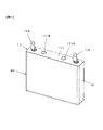
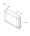
図1に示すように、リチウムイオン電池BCは、一端部に開口を有する容器10と、容器10内に収容された図2に示す発電要素組立体11とを含んで構成されている。容器10は、横断面形状が扁平な長方形、隅丸長方形あるいは隅丸長円形の有底角筒状のケースである。したがって、容器10は、幅広側面と幅狭側面と底面とで形成されている。
[Configuration of square battery]
As shown in FIG. 1, the lithium ion battery BC includes a
[発電要素組立体]
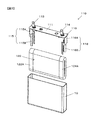
図2に示す発電要素組立体11は、図3および4に示す蓋組立体110と、図3および図5に示す捲回体120とを備えている。
[Power generation element assembly]
A power
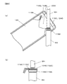
[蓋組立体]
図2〜4、とくに図4に示すように、蓋組立体110は、容器10の開口を塞ぐ蓋111と、絶縁シール部材112を介して蓋111から突出する正負極外部端子113,114と、正負極外部端子113,114にそれぞれ接続された正負極集電体115,116とを備えている。正負極外部端子113,114と正負極集電体115,116は、絶縁シール部材112により蓋111と電気的に絶縁されている。
[Lid assembly]
As shown in FIGS. 2 to 4, particularly FIG. 4, the
正極集電体115は、集電体基部115Aと一対の正極集電体接続片(二股接続片)115Bとを備える。基部115Aは、蓋111の裏面に絶縁材を介して接する水平平板と、水平平板から容器底部に向けて折れ曲がる垂直平板とを有する。垂直平板は、容器10の幅狭側面に沿って二次電池底部方向に延在する。二股接続片115Bは、基部115Aの垂直平板の下端両側面から二股に分岐しつつ、容器底部方向に延びる一対の正極接続片である。一対の接続片115Bは、図4(b)に示すように、容器10の上方から見て、すなわち横断面形状においては、先端に近づくほど接続片同士の間隔が狭くなるように傾斜している。一対の接続片115Bの一対の内面115Cは、後述するように捲回体120の正極未塗工部122A(図6参照)の外表面と接合される。
The positive electrode
同様に、負極集電体116は、集電体基部116Aと一対の負極集電体接続片(二股接続片)116Bとを備える。基部116Aは、蓋111の裏面に絶縁材を介して接する水平平板と、水平平板から容器底部に向けて折れ曲がる垂直平板とを有する。垂直平板は、容器10の幅狭側面に沿って二次電池底部方向に延在する。二股接続片116Bは、基部116Aの垂直平板の下端両側面から二股に分岐しつつ、容器底部方向に延びる一対の負極接続片である。一対の接続片116Bは、図4(b)に示すように、容器10の上方から見て、すなわち横断面形状においては、先端に近づくほど接続片同士の間隔が狭くなるように傾斜している。一対の接続片116Bの一対の内面116Cは、後述するように捲回体120の負極未塗工部124A(図6参照)の外表面と接合される。
Similarly, the negative electrode
後述するように、一対の正極接続片115Bは、捲回体120の一端側で正極接続部122Aの積層体122Cを挟持し、一対の負極接続片116Bは、捲回体120の他端側で負極接続部124Aの積層体124Cを挟持するように、捲回体120を挟み込む。
As will be described later, the pair of positive
正極集電体115は、正極シート122の正極接続部122Aを正極外部端子113に電気的に接続する。一対の二股接続片115Bは、それぞれが正極接続部122Aの表裏面に接する接合面115Cを有する。負極集電体116は、負極シート124の負極接続部124Aを負極外部端子114に電気的に接続する。一対の二股接続片116Bは、それぞれが負極接続部124Aの表裏面に接する接合面116Cを有する。
The positive electrode
捲回体120の両端面において、正極接続部122Aの正極シート積層体122Cおよび負極接続部124Aの負極シート積層体124Cは、内側から押し広げられて2つの積層体に分離される。分離された積層体のそれぞれは容器外方に向けて広がるように傾斜した外周面を有している。(図6(b)参照)その外周面に正負極集電体115,116の二股接続片115B,116Bの接合面115C,116Cがそれぞれ溶接される。
On both end faces of the
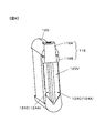
[捲回体]
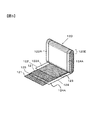
図5に示すように、捲回体120は、セパレータ121を挟んで正極箔(正極シート)122と負極箔(負極シート)124とを図示しない軸芯の周りに扁平形状に捲回して構成されている。正極箔122はアルミニウム箔もしくはアルミニウム合金箔であり、負極箔124は銅箔もしくは銅合金箔である。また、セパレータ121は多孔質のポリエチレン樹脂である。
なお、軸芯は、セパレータを複数回捲回して形成してもよいし、樹脂製の平板を軸芯として用いてもよい。
[Wound body]
As shown in FIG. 5, the
The shaft core may be formed by winding the separator a plurality of times, or a resin flat plate may be used as the shaft core.
正極箔122の両面には正極活物質(正極電極)123が塗布されており、負極箔124の両面には負極活物質(負極電極)125が塗布されている。捲回体120の一端には、正極活物質123が塗布されていない、正極箔122が露出した正極接続部(未塗工部とも呼ぶ)122Aが設けられている。反対側の負極側端面にも、負極活物質125が塗布されていない、負極箔124が露出した負極接続部(未塗工部とも呼ぶ)124Aが設けられている。正負極箔122,124は、後述するように、正負極接続部122A,124Aにおいて、正負極集電体115,116にそれぞれ接続される。
A positive electrode active material (positive electrode) 123 is applied to both surfaces of the
以上のような角形電池の製造工程について説明する。
[角形電池の組立]
蓋組立体110と捲回体120を一体化して図2に示す発電要素組立体11を製作し、この発電要素組立体11を容器10に挿入する。蓋111を容器10にレーザ溶接して容器10が封止される。蓋111には注液口が設けられ、蓋111を容器10に溶接した後に、注液口から容器10内に電解液(図示省略)が注入される。電解液注入後、注液口には注液栓111Aがレーザ溶接されて封止される。正負極外部端子113,114には、絶縁樹脂よりなるガスケット112が装着され、蓋111に対して電気的に絶縁され、同時に、正負極外部端子113,114と蓋111の間の封水がなされている。111Bはガス排出口である。
The manufacturing process of the above square battery is demonstrated.
[Assembly of square battery]
The power
[発電要素組立体の組立]
発電要素組立体11の組み立て手順を説明する。
まず、図5に示した捲回体120を作成する。すなわち、セパレータ121を1周以上捲回して形成した軸芯の周りに、正極箔122および負極箔124をセパレータ121で絶縁しつつ積層して捲回する。捲回体120の最外表面のセパレータ121は図示しないテープで係止される。
[Assembly of power generation element assembly]
The assembly procedure of the power
First, the
捲回体120と集電体115,116を一体化するに先立って、捲回体120の未塗工部122A,124Aを厚さ方向に押しつぶして変形させておく。捲回体120の正極接続部122Aの外表面に正極集電体115の一対の二股状接続片115Bの内表面115Cが接するようにし、かつ、負極接続部124Aの外表面に負極集電体116の一対の二股状負極接続片116Bの内表面116Cが接するように、正極集電体115の一対の接続片115Bの間と、負極集電体116の一対の接続片116Bとの間に捲回体120を挿入する。この状態を図6図(a)に示す。図6(a)は、角形電池の正極側端部の横断面図である。
Prior to integrating the
たとえば、正極集電体115はアルミニウムで製作されている。また、正極箔122はアルミニウム箔であり、捲回体120において何重にも重ねられている。負極集電体116は銅で製作されている。また、負極箔124は銅箔であり、捲回体120において何重にも重ねられている。
For example, the positive electrode
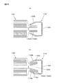
集電体115,116の間に捲回体120を挿入した後、図6(b)に示すように、捲回体120の端面において、正極接続部122Aの積層体122Cをその内周側から外側に押し開いて2つの積層体に分離する。図7にも示すように、捲回体120の端面の積層体122CをV字状に拡げて溶接用空間120Vを形成する。負極接続部124Aの端面も同様である。
なお、図6は概念図であり、図8の図面と整合していない。
After the winding
FIG. 6 is a conceptual diagram and is not consistent with the drawing of FIG.
捲回体120の両端面の未塗工部積層体122C,124Cを外側に押し開いて2つの積層体に分離した後、図8に示すように、分離された積層体ごとに接続片115,116と溶接する。すなわち、超音波接合の超音波振動子(ホーン)WHと固定子(アンビル)WAとにより、負極接続部(未塗工部)124Aの分離された積層体124Cと二股状の負極接続片116Bとを挟み込んで超音波溶接する。図示は省略するが、同様に、正極接続部(未塗工部)122Aの積層体122Cと二股状の正極接続片115Bとを超音波接合の超音波振動子WHと固定子WAとにより挟み込んで超音波溶接する。
After the uncoated part laminates 122C and 124C on both end faces of the
すなわち、図8(b)に示すように、二股接続片115B,116Bの接合面115C,116Cの法線に沿って超音波振動子WHと固定子WAとを対向配置する。固定子WAおよび超音波振動子WHのいずれか一方、実施形態では超音波振動子WHを積層体122C,124Cの内周面に当接させ、固定子WAおよび超音波振動子WHのいずれか他方、実施形態では固定子WAを二股接続片115B,116Bの外表面に当接させる。超音波振動子WHを固定子WAに対して加圧しつつ超音波振動子WHに溶接エネルギを印加すると、積層体122C,124Cと接合面115C,116Cとが超音波溶接により接合される。これによって、捲回体120の正負極未塗工部122Aと124Aは、正負極集電体115,116に電気的に接続される。
That is, as shown in FIG. 8B, the ultrasonic transducer WH and the stator WA are arranged to face each other along the normal line of the
未塗工部122A、124Aは、例えば、周方向2箇所で接続片115B、116Bに溶接され、正極箔122、負極箔124から集電体115,116に至る通電経路を短縮し得るとともに、接続抵抗を小さくでき、電池の出力を高めることができる。
The
以上の組立手順により、図9に示すように、捲回体120の表裏面に露出した負極接続部124Aの積層体124Cは、正極集電体116の接続片116Bと一体化して接続される。また、図示は省略するが、捲回体120の表裏面に露出した正極接続部122Aの積層体122Cは、負極集電体115の接続片115Bと一体化して接続される。
Through the above assembly procedure, as shown in FIG. 9, the
以上説明した角形電池の製造方法は、蓋111の正負極外部端子113,114と正負極集電体115,116をそれぞれ接続して蓋組立体を製作する工程と、正極シート122と負極シート124をセパレータ121を介して捲回して扁平形状に捲回体120を形成する工程と、蓋組立体110を捲回体120と一体化する工程と、捲回体120の捲回軸方向両端面において、正極シート122および負極シート124の活物質が塗布されていない正極接続部122Aおよび負極接続部124Aの積層体122C,124Cを内側から外側に押し広げて2つの積層体に分離する工程と、分離された2つの積層体を正負極集電体115,116の二股接続片115B,116Bに接続する工程とを備え、接続する工程は、二股接続片115B,116Bの一方の接続片の接合面115C,116Cの法線に沿って超音波振動子WHと固定子WAとを配置する工程と、固定子WAおよび超音波振動子WHのいずれか一方を2つに分離された一方の積層体の内周面に、固定子および超音波振動子のいずれか他方を二股接続片115B,116Bの一方の接続片115,116Bの外周面に当接させ、超音波振動子と固定子により、2つに分離された積層体と接合面とを挟圧し、超音波振動子に溶接エネルギを印加して積層体と接合面とを溶接する工程とを含む。
The rectangular battery manufacturing method described above includes the steps of manufacturing the lid assembly by connecting the positive and negative
なお、超音波振動子WHと固定子WAの位置関係は問わない。すなわち、超音波振動子WHを二股接続片115B,116Bの外表面に当接し、固定子WAをシート積層体122C,124Cに当接するようにしてもよい。
The positional relationship between the ultrasonic transducer WH and the stator WA is not limited. That is, the ultrasonic transducer WH may be brought into contact with the outer surfaces of the
以上説明した実施形態による角形リチウムイオン電池は次のような作用効果を奏することができる。 The prismatic lithium ion battery according to the embodiment described above can achieve the following operational effects.
(1)捲回体120の捲回軸方向の両端面は、容器10の長手方向両端部の幅狭側面と対向している。正負極集電体115,116のそれぞれの二股接続片115B,116Bは、容器10の幅狭側面に沿って容器10の底部に向けて延設されている。捲回体120の両端部の正負極接続部122A,124Aの端面は、内周側から外周側に押し広げられて2つの積層体に分離されている。2つに分離された積層体122C,124Cのそれぞれは、幅狭側面に向けて広がるように傾斜する。分離された積層体122C,124Cの外周面が、正負極集電体115,116の二股接続片115B,116Bの接合面115C,116Cと溶接されている。
(1) Both end surfaces of the winding
すなわち、捲回体120の未塗工部122A,124Aの金属箔122,124、すなわち積層体122C,124Cを二つに振り分けて溶接するので、金属箔の枚数は半分となる。これによって、溶接強度は安定し、溶接エネルギが低減できることから汚損の発生もなくなり、品質向上につながる。
That is, since the metal foils 122 and 124 of the
従来、捲回体120の未塗工部122A,124Aを捲回中心方向に一括、圧縮して、1体の積層部として集電体に溶接する電池があったが、積層部の正負極の枚数が多いため、溶接強度が不安定になったり、汚損が発生する等、品質不良につながる可能性があった。
Conventionally, there has been a battery in which the
(2)二股接続片115B,116Bの一対の接合面115C,116Cは、分離して傾斜する積層体122C,124Cの外周面と接合するよう、容器10の幅狭側面から容器10内方に向かって先細るように傾斜し、二股接続片115B,116Bは、2つに分離されて傾斜する積層体122C,124Cの外周面と対応した角度で傾斜するハの字形状に形成されている。すなわち、二股接続片115B,116Bは、二股接続片115B,116Bの内側にそれぞれ形成された一対の接合面115C,116Cが、一方の接合面115C,116Cの法線方向に他方の接合面115C,116Cが配設されないような傾斜角でハの字形状に形成されている。
(2) The pair of
したがって、超音波振動子WHと固定子WAを接合面115C,116Cの法線に沿って配置することができる。この配置により、二股接続片115B,116Bの一方の接合面115C,116Cの法線方向に他方の接合面115C,116Cが位置しないので、凹部120Vに位置する超音波振動子WHが他方の接合面115C,116C、すなわち、二股接続片115B,116Bの他方と干渉しない。
Therefore, the ultrasonic transducer WH and the stator WA can be disposed along the normal line of the
このように配置した超音波振動子WHと固定子WAにより積層体122C,124Cと二股接続片115B,116Bとを挟圧し、超音波振動子WHに溶接エネルギを印加して積層体122C,124Cを接合面115C,116Cに溶接すれば、溶接品質に必要な圧力を超音波振動子から被溶接対象に与えたとき、固定子が変形することがなく、溶接品質を担保することができる。
The
特許文献1の電池では、固定子が片持ち支持されているから、超音波振動子から十分な
溶接圧力を印加できなかったり、あるいは、十分な圧力を印加すると固定子が撓んでしまい、結局、溶接の品質が担保されないおそれがある。
In the battery of Patent Document 1, since the stator is cantilevered, a sufficient welding pressure cannot be applied from the ultrasonic vibrator, or the stator is bent when a sufficient pressure is applied. There is a risk that the quality of welding may not be guaranteed.
(3)捲回体120の上辺の円弧部120Eは、捲回体120の作製時には、二股接続片115B,116Bの間隔よりも幅広に形成され、円弧部120Eを短径方向に圧縮した後に、二股接続片115B,116Bを嵌装する。これによって、嵌装の工程は容易になる。円弧部120Eは接続板部115,116に溶接される部分でないため、圧縮による品質低下等の問題は生じない。
(3) When the
(4)従来、集電体を捲回体未塗工部122A,124Aに溶接した後に、集電体を蓋板に固定接続する電池があったが、蓋と捲回体の隙間が狭くなるために固定加工が困難となり、また加工工程中に捲回体を傷つけたり、異物が付着して著しく品質劣化を招く恐れがあった。
(4) Conventionally, there has been a battery in which the current collector is fixedly connected to the cover plate after the current collector is welded to the
本実施形態では、蓋板111に集電体115,116を固定接続した後に、容易な作業によって、集電体115,116を捲回体120に嵌装し、溶接できることから、品質劣化を招く恐れはなく、生産性が高まるとともに、生産コストを低下し得る。
In the present embodiment, the
以上の説明では、積層体122C,124Cを内周側から外周側に向けて押し広げて2つの積層体に分離する方法については言及しなかったが、次のように、各種の方法を用いることができる。
The above description did not mention the method of spreading the
捲回体120とは別に、開閉可能な拡開部材を準備し、捲回体120の端面から捲回体120の中心部にその拡開部材を挿入して開き操作し、積層体を内周から外方に左右に押し広げることができる。この場合、積層体122C,124Cをそれぞれ内側から外側へ拡げて2つに分離した後、拡開部材を取り外してもよいし、支障がなければ、拡開部材を取り外さなくてもよい。捲回体120の最内周部に予め拡開部材を設けておいてもよい。
Separately from the winding
拡開部材は、たとえば1枚の板材を2つ折りにしたものであり、その折り曲げ基部は、捲回体120の内方で折れ曲がり線が捲回体端面の長軸方向に延在するように配置する。これにより、折れ曲がり基部を支点として一対の平板を開くことにより、積層体122C、124Cを内周から外方に押し開いて2つの積層体に分離することができる。
The spreading member is, for example, a sheet material folded in half, and the bent base portion is arranged so that the bent line extends in the long axis direction of the end surface of the wound body inside the
このように、拡開部材を用いることにより、正負極箔122,124に損傷を与えることなく、変形や損傷が生じやすい箔積層体122C,124Cを容易に拡開できる。
As described above, by using the expanding member, the foil laminates 122C and 124C that are likely to be deformed or damaged can be easily expanded without damaging the positive and
以上の説明は実施形態であり、本発明の趣旨に逸脱しない種々の構造の角形電池に本発明を適用することができる。
したがって、本発明は、角形電池の各構成部品の形状、構造は実施形態のものに限定されず、捲回体120の捲回軸方向の両端面において、正極接続部122Aにおける正極シート122の積層体122Cおよび負極接続部124Aにおける負極シート124の積層体124Cが、内周側から外周側に向けて扁平形状の容器10の厚さ方向に押し広げられて2つの積層体に分離され、正負極集電体115,116の二股接続片115B,116Bの接合面115C、116Cの各々が、分離された積層体の外周面の各々と接合して溶接されている種々の形態の角形電池に適用することができる。
The above description is an embodiment, and the present invention can be applied to prismatic batteries having various structures that do not depart from the spirit of the present invention.
Therefore, the present invention is not limited to the shape and structure of each component of the prismatic battery according to the embodiment, and the
BC:角形電池
10:容器
11:発電要素組立体
110:蓋組立体
111:蓋
113:正極外部端子
114:負極外部端子
115:正極集電体
116:負極集電体
115A,116A:集電体基部
115B,116B:集電体接続片(二股接続片)
115C,116C:超音波接合面
120:捲回体
121:セパレータ
122:正極箔
123:正極電極
124:負極箔
125:負極電極
WA:固定子
WH:超音波振動子
BC: Rectangular battery 10: Container 11: Power generation element assembly 110: Lid assembly 111: Lid 113: Positive external terminal 114: Negative external terminal 115: Positive current collector 116: Negative
115C, 116C: Ultrasonic bonding surface 120: Winding body 121: Separator 122: Positive electrode foil 123: Positive electrode 124: Negative electrode foil 125: Negative electrode WA: Stator WH: Ultrasonic vibrator
Claims (6)
前記捲回体が収納された扁平形状の容器と、
前記容器を封止する蓋と、
前記蓋に設けられた正極外部端子および負極外部端子と、
前記正極シートの正極接続部を前記正極外部端子に電気的に接続する正極集電体であって、前記正極接続部の表裏面にそれぞれ接する接合面が形成された二股接続片を有する正極集電体と、
前記負極シートの負極接続部を前記負極外部端子に電気的に接続する負極集電体であって、前記負極接続部の表裏面にそれぞれ接する接合面が形成された二股接続片を有する負極集電体とを備え、
前記捲回体の捲回軸方向の両端面において、前記正極接続部における正極シートの積層体および前記負極接続部における負極シートの積層体は、内周側から外周側に向けて扁平形状の容器の厚さ方向に押し広げられて2つの積層体に分離され、前記正負極集電体の二股接続片の接合面の各々は、前記分離された前記積層体の外周面の各々と接合して溶接されていることを特徴とする角形電池。 A positive electrode sheet coated with a positive electrode active material and a negative electrode sheet coated with a negative electrode active material are wound into a flat shape through a separator, and the positive and negative electrode active materials not coated with the positive and negative electrode active materials are not coated on both ends. A wound body provided with a construction part as a positive and negative electrode connection part;
A flat container in which the wound body is stored;
A lid for sealing the container;
A positive external terminal and a negative external terminal provided on the lid;
A positive electrode current collector for electrically connecting a positive electrode connection portion of the positive electrode sheet to the positive electrode external terminal, wherein the positive electrode current collector has a bifurcated connection piece formed with joint surfaces respectively contacting the front and back surfaces of the positive electrode connection portion Body,
A negative electrode current collector for electrically connecting a negative electrode connection portion of the negative electrode sheet to the negative electrode external terminal, wherein the negative electrode current collector has a bifurcated connection piece formed with joint surfaces respectively contacting the front and back surfaces of the negative electrode connection portion With body,
On both end faces in the winding axis direction of the winding body, the laminate of the positive electrode sheet in the positive electrode connection portion and the laminate of the negative electrode sheet in the negative electrode connection portion are flattened from the inner peripheral side toward the outer peripheral side. Each of the joint surfaces of the bifurcated connecting piece of the positive and negative electrode current collectors is joined to each of the outer peripheral surfaces of the separated laminate. A prismatic battery that is welded.
前記捲回体の両端面は、前記容器の長手方向両端部の幅狭側面と対向しており、
前記正負極集電体のそれぞれの二股接続片は、前記容器の前記幅狭側面に沿って前記容器の底部に向けて延設され、
前記2つに分離された積層体は前記幅狭側面に向けて広がるように傾斜し、その傾斜した2つの積層体の外周面の各々に前記正負極集電体の二股接続片の接合面がそれぞれ溶接されていることを特徴とする角形電池。 In the rectangular battery according to claim 1,
Both end surfaces of the wound body are opposed to narrow side surfaces at both ends in the longitudinal direction of the container,
Each bifurcated connection piece of the positive and negative electrode current collectors extends toward the bottom of the container along the narrow side surface of the container,
The two separated laminates are inclined so as to spread toward the narrow side surface, and the joint surface of the bifurcated connecting piece of the positive and negative electrode current collector is formed on each of the outer peripheral surfaces of the two inclined laminates. A square battery characterized by being welded to each other.
前記二股接続片は、その一対の接合面が、前記2つに分離された積層体の外周面に対応した角度を有する面となるように、前記容器の幅狭側面から容器内方に向かって先細るハの字形状に形成されていることを特徴とする角形電池。 The prismatic battery according to claim 1 or 2,
The bifurcated connecting piece is directed from the narrow side surface of the container toward the inside of the container so that the pair of joint surfaces have an angle corresponding to the outer peripheral surface of the two separated laminates. A prismatic battery characterized by being formed in a tapered C-shape.
前記二股接続片は、前記二股接続片の内側にそれぞれ形成された一対の接合面が、一方の接合面の法線方向に他方の接合面が配設されないような傾斜角でハの字形状に形成されていることを特徴とする角形電池。 The prismatic battery according to any one of claims 1 to 3,
The bifurcated connection piece has a pair of joint surfaces formed on the inner side of the bifurcated connection piece and has a square shape with an inclination angle such that the other joint surface is not disposed in the normal direction of the one joint surface. A prismatic battery that is formed.
前記蓋の正負極外部端子と前記正負極集電体をそれぞれ接続して蓋組立体を製作する工程と、
正極シートと負極シートをセパレータを介して捲回して扁平形状に捲回体を形成する工程と、
前記蓋組立体を前記捲回体と一体化する工程と、
前記捲回体の捲回軸方向両端面において、前記正極シートおよび負極シートの活物質が塗布されていない正極接続部および負極接続部の積層体を内側から外側に押し広げて2つの積層体に分離する工程と、
前記分離された2つの積層体を前記正負極集電体の前記二股接続片に接続する工程とを備えることを特徴とする角形電池の製造方法。 In the manufacturing method of the square battery according to any one of claims 1 to 4,
Connecting the positive and negative external terminals of the lid and the positive and negative current collectors to produce a lid assembly;
Winding the positive electrode sheet and the negative electrode sheet through a separator to form a wound body in a flat shape;
Integrating the lid assembly with the wound body;
On both end surfaces in the winding axis direction of the winding body, the positive electrode connection portion and the negative electrode connection portion, to which the active material of the positive electrode sheet and the negative electrode sheet is not applied, are spread outwardly from the inside to the two laminate bodies. Separating, and
Connecting the two separated laminates to the bifurcated connecting piece of the positive and negative electrode current collectors.
前記接続する工程は、
前記二股接続片の一方の接続片の接合面の法線に沿って超音波振動子と固定子とを配置する工程と、
前記固定子および超音波振動子のいずれか一方を前記2つに分離された一方の積層体の内周面に、前記固定子および超音波振動子のいずれか他方を前記二股接続片の一方の接続片の外周面に当接させ、前記超音波振動子と前記固定子により、2つに分離された積層体と前記接合面とを挟圧し、前記超音波振動子に溶接エネルギを印加して前記2つに分離された積層体と前記接合面とを溶接する工程とを含むことを特徴とする角形電池の製造方法。 In the manufacturing method of the square battery according to claim 5,
The connecting step includes
Arranging the ultrasonic vibrator and the stator along the normal line of the joint surface of one of the forked connection pieces;
Either one of the stator and the ultrasonic transducer is arranged on the inner peripheral surface of one of the two separated bodies, and the other of the stator and the ultrasonic transducer is arranged on one of the two-forked connection piece. Abutting on the outer peripheral surface of the connecting piece, the ultrasonic transducer and the stator sandwich the two separated laminate and the joint surface, and apply welding energy to the ultrasonic transducer. A method of manufacturing a prismatic battery, comprising the step of welding the two separated laminates and the joint surface.
Priority Applications (2)
| Application Number | Priority Date | Filing Date | Title |
|---|---|---|---|
| JP2010057235A JP5135368B2 (en) | 2010-03-15 | 2010-03-15 | Square battery and method for manufacturing the same |
| US13/028,427 US8986874B2 (en) | 2010-03-15 | 2011-02-16 | Prismatic cell and production method for the same |
Applications Claiming Priority (1)
| Application Number | Priority Date | Filing Date | Title |
|---|---|---|---|
| JP2010057235A JP5135368B2 (en) | 2010-03-15 | 2010-03-15 | Square battery and method for manufacturing the same |
Publications (2)
| Publication Number | Publication Date |
|---|---|
| JP2011192517A true JP2011192517A (en) | 2011-09-29 |
| JP5135368B2 JP5135368B2 (en) | 2013-02-06 |
Family
ID=44560294
Family Applications (1)
| Application Number | Title | Priority Date | Filing Date |
|---|---|---|---|
| JP2010057235A Active JP5135368B2 (en) | 2010-03-15 | 2010-03-15 | Square battery and method for manufacturing the same |
Country Status (2)
| Country | Link |
|---|---|
| US (1) | US8986874B2 (en) |
| JP (1) | JP5135368B2 (en) |
Cited By (13)
| Publication number | Priority date | Publication date | Assignee | Title |
|---|---|---|---|---|
| WO2012023392A1 (en) * | 2010-08-19 | 2012-02-23 | 株式会社Gsユアサ | Power storage element provided with a current collector, and method of manufacturing current collector |
| WO2012176704A1 (en) * | 2011-06-24 | 2012-12-27 | 日立ビークルエナジー株式会社 | Secondary battery |
| JP2013125657A (en) * | 2011-12-14 | 2013-06-24 | Mitsubishi Motors Corp | Battery |
| JP2013131468A (en) * | 2011-12-22 | 2013-07-04 | Mitsubishi Motors Corp | Collector member, and battery with collector member |
| JP2013134899A (en) * | 2011-12-26 | 2013-07-08 | Mitsubishi Motors Corp | Battery |
| JP2013206607A (en) * | 2012-03-27 | 2013-10-07 | Toyota Industries Corp | Power storage device, vehicle, and connection method |
| JP2014022337A (en) * | 2012-07-23 | 2014-02-03 | Sharp Corp | Nonaqueous secondary battery and liquid injection method therefor |
| JP2015141847A (en) * | 2014-01-29 | 2015-08-03 | 株式会社東芝 | Secondary battery and method for manufacturing secondary battery |
| JP2015195218A (en) * | 2015-06-19 | 2015-11-05 | 三菱自動車工業株式会社 | battery |
| US9583783B2 (en) | 2012-08-31 | 2017-02-28 | Hitachi Automotive Systems, Ltd. | Prismatic secondary battery |
| US10050299B2 (en) | 2012-08-09 | 2018-08-14 | Gs Yuasa International Ltd | Manufacturing method of electric storage apparatus, auxiliary plate for ultrasonic welding, and electric storage apparatus |
| US10734655B2 (en) | 2012-05-10 | 2020-08-04 | Gs Yuasa International Ltd. | Electric storage device |
| CN113300031A (en) * | 2021-05-21 | 2021-08-24 | 东莞塔菲尔新能源科技有限公司 | Power battery and welding method thereof |
Families Citing this family (13)
| Publication number | Priority date | Publication date | Assignee | Title |
|---|---|---|---|---|
| JP5772753B2 (en) * | 2012-07-30 | 2015-09-02 | トヨタ自動車株式会社 | Manufacturing method of secondary battery |
| DE102014211102A1 (en) * | 2014-06-11 | 2015-12-17 | Robert Bosch Gmbh | battery cell |
| EP3149789B1 (en) * | 2014-06-30 | 2021-02-24 | BYD Company Limited | Battery |
| CN105428584B (en) | 2014-09-11 | 2020-05-01 | 株式会社杰士汤浅国际 | Electric storage element |
| DE102014222261A1 (en) | 2014-10-31 | 2016-05-04 | Bayerische Motoren Werke Aktiengesellschaft | Current collector for an electrochemical energy storage device |
| KR102361705B1 (en) * | 2015-03-03 | 2022-02-10 | 삼성에스디아이 주식회사 | Rechargeable battery having cover |
| JP6837796B2 (en) * | 2016-09-30 | 2021-03-03 | 三洋電機株式会社 | Non-aqueous electrolyte secondary battery |
| EP3316337B1 (en) * | 2016-10-26 | 2019-12-04 | VARTA Microbattery GmbH | Battery, lead tab therefor and method for producing a lead tab and a battery |
| JP7194600B2 (en) * | 2019-01-29 | 2022-12-22 | 三洋電機株式会社 | Method for manufacturing secondary battery |
| JP7229027B2 (en) * | 2019-01-29 | 2023-02-27 | 三洋電機株式会社 | Secondary battery and manufacturing method thereof |
| JP7333001B2 (en) * | 2019-12-26 | 2023-08-24 | トヨタ自動車株式会社 | Batteries and battery holders |
| CN112382831B (en) * | 2020-09-09 | 2022-09-06 | 万向一二三股份公司 | A utmost point ear and utmost point ear welding set for laminate polymer battery |
| CN214411333U (en) * | 2021-03-30 | 2021-10-15 | 珠海冠宇电池股份有限公司 | Battery and terminal equipment |
Citations (9)
| Publication number | Priority date | Publication date | Assignee | Title |
|---|---|---|---|---|
| JP2003249423A (en) * | 2001-12-20 | 2003-09-05 | Toyota Motor Corp | Storage element and manufacturing method |
| JP2003346903A (en) * | 2002-05-28 | 2003-12-05 | Japan Storage Battery Co Ltd | Battery |
| JP2005032477A (en) * | 2003-07-08 | 2005-02-03 | Toyota Motor Corp | Battery and automobile mounting it |
| JP2005216825A (en) * | 2004-02-02 | 2005-08-11 | Matsushita Electric Ind Co Ltd | Square battery and its manufacturing method |
| JP2006012836A (en) * | 2004-06-23 | 2006-01-12 | Samsung Sdi Co Ltd | Secondary battery |
| JP2006228551A (en) * | 2005-02-17 | 2006-08-31 | Toyota Motor Corp | Current collector terminal, and power storage device provided with the same |
| JP2007019017A (en) * | 2005-07-05 | 2007-01-25 | Samsung Sdi Co Ltd | Secondary cell |
| JP2007335150A (en) * | 2006-06-13 | 2007-12-27 | Honda Motor Co Ltd | Power storage element |
| JP2011165515A (en) * | 2010-02-10 | 2011-08-25 | Sanyo Electric Co Ltd | Square sealed secondary battery and method for manufacturing the same |
Family Cites Families (3)
| Publication number | Priority date | Publication date | Assignee | Title |
|---|---|---|---|---|
| US7718312B2 (en) * | 2002-05-27 | 2010-05-18 | Gs Yuasa Corporation | Battery |
| JP5211086B2 (en) * | 2010-02-08 | 2013-06-12 | 日立ビークルエナジー株式会社 | Secondary battery |
| WO2011111196A1 (en) | 2010-03-10 | 2011-09-15 | 日立ビークルエナジー株式会社 | Prismatic battery and method for fabricating same |
-
2010
- 2010-03-15 JP JP2010057235A patent/JP5135368B2/en active Active
-
2011
- 2011-02-16 US US13/028,427 patent/US8986874B2/en active Active
Patent Citations (9)
| Publication number | Priority date | Publication date | Assignee | Title |
|---|---|---|---|---|
| JP2003249423A (en) * | 2001-12-20 | 2003-09-05 | Toyota Motor Corp | Storage element and manufacturing method |
| JP2003346903A (en) * | 2002-05-28 | 2003-12-05 | Japan Storage Battery Co Ltd | Battery |
| JP2005032477A (en) * | 2003-07-08 | 2005-02-03 | Toyota Motor Corp | Battery and automobile mounting it |
| JP2005216825A (en) * | 2004-02-02 | 2005-08-11 | Matsushita Electric Ind Co Ltd | Square battery and its manufacturing method |
| JP2006012836A (en) * | 2004-06-23 | 2006-01-12 | Samsung Sdi Co Ltd | Secondary battery |
| JP2006228551A (en) * | 2005-02-17 | 2006-08-31 | Toyota Motor Corp | Current collector terminal, and power storage device provided with the same |
| JP2007019017A (en) * | 2005-07-05 | 2007-01-25 | Samsung Sdi Co Ltd | Secondary cell |
| JP2007335150A (en) * | 2006-06-13 | 2007-12-27 | Honda Motor Co Ltd | Power storage element |
| JP2011165515A (en) * | 2010-02-10 | 2011-08-25 | Sanyo Electric Co Ltd | Square sealed secondary battery and method for manufacturing the same |
Cited By (20)
| Publication number | Priority date | Publication date | Assignee | Title |
|---|---|---|---|---|
| US8828590B2 (en) | 2010-08-19 | 2014-09-09 | Gs Yuasa International Ltd. | Electric storage device provided with current collecting member, and method for manufacturing current collecting member |
| WO2012023392A1 (en) * | 2010-08-19 | 2012-02-23 | 株式会社Gsユアサ | Power storage element provided with a current collector, and method of manufacturing current collector |
| US9123475B2 (en) | 2010-08-19 | 2015-09-01 | Gs Yuasa International Ltd. | Electric storage device provided with current collecting member, and method for manufacturing current collecting member |
| WO2012176704A1 (en) * | 2011-06-24 | 2012-12-27 | 日立ビークルエナジー株式会社 | Secondary battery |
| JP2013008559A (en) * | 2011-06-24 | 2013-01-10 | Hitachi Vehicle Energy Ltd | Secondary battery |
| US9252453B2 (en) | 2011-06-24 | 2016-02-02 | Hitachi Automotive Systems, Ltd. | Rechargeable battery |
| JP2013125657A (en) * | 2011-12-14 | 2013-06-24 | Mitsubishi Motors Corp | Battery |
| KR101412323B1 (en) | 2011-12-14 | 2014-06-25 | 미쯔비시 지도샤 고교 가부시끼가이샤 | Battery |
| JP2013131468A (en) * | 2011-12-22 | 2013-07-04 | Mitsubishi Motors Corp | Collector member, and battery with collector member |
| JP2013134899A (en) * | 2011-12-26 | 2013-07-08 | Mitsubishi Motors Corp | Battery |
| JP2013206607A (en) * | 2012-03-27 | 2013-10-07 | Toyota Industries Corp | Power storage device, vehicle, and connection method |
| US10734655B2 (en) | 2012-05-10 | 2020-08-04 | Gs Yuasa International Ltd. | Electric storage device |
| JP2014022337A (en) * | 2012-07-23 | 2014-02-03 | Sharp Corp | Nonaqueous secondary battery and liquid injection method therefor |
| US10050299B2 (en) | 2012-08-09 | 2018-08-14 | Gs Yuasa International Ltd | Manufacturing method of electric storage apparatus, auxiliary plate for ultrasonic welding, and electric storage apparatus |
| US9583783B2 (en) | 2012-08-31 | 2017-02-28 | Hitachi Automotive Systems, Ltd. | Prismatic secondary battery |
| WO2015115494A1 (en) * | 2014-01-29 | 2015-08-06 | 株式会社 東芝 | Secondary battery and secondary battery production method |
| US10418612B2 (en) | 2014-01-29 | 2019-09-17 | Kabushiki Kaisha Toshiba | Secondary battery and a method of manufacturing secondary battery |
| JP2015141847A (en) * | 2014-01-29 | 2015-08-03 | 株式会社東芝 | Secondary battery and method for manufacturing secondary battery |
| JP2015195218A (en) * | 2015-06-19 | 2015-11-05 | 三菱自動車工業株式会社 | battery |
| CN113300031A (en) * | 2021-05-21 | 2021-08-24 | 东莞塔菲尔新能源科技有限公司 | Power battery and welding method thereof |
Also Published As
| Publication number | Publication date |
|---|---|
| US8986874B2 (en) | 2015-03-24 |
| US20110223454A1 (en) | 2011-09-15 |
| JP5135368B2 (en) | 2013-02-06 |
Similar Documents
| Publication | Publication Date | Title |
|---|---|---|
| JP5135368B2 (en) | Square battery and method for manufacturing the same | |
| JP6093874B2 (en) | Prismatic secondary battery | |
| JP4588331B2 (en) | Square battery and manufacturing method thereof | |
| JP6427462B2 (en) | Square secondary battery | |
| JP6931460B2 (en) | Batteries and battery manufacturing methods | |
| JP6363893B2 (en) | Secondary battery | |
| US8530068B2 (en) | Square battery and manufacturing method of the same | |
| JP7064695B2 (en) | Sealed battery, assembled battery, manufacturing method of sealed battery and manufacturing method of assembled battery | |
| JP6867746B2 (en) | Power storage element | |
| JP6755183B2 (en) | Lithium electrochemical storage batteries with terminals directly attached to the electrochemical assembly and related manufacturing methods | |
| JP2007026945A (en) | Battery and manufacturing method thereof | |
| JP2008004274A (en) | Storage element | |
| JP5122617B2 (en) | Rectangular secondary battery and method for manufacturing the same | |
| JP6550863B2 (en) | STORAGE DEVICE AND METHOD FOR MANUFACTURING STORAGE DEVICE | |
| JP2012243403A (en) | Secondary battery | |
| JP6476746B2 (en) | STORAGE DEVICE, POWER SUPPLY MODULE, AND METHOD FOR MANUFACTURING STORAGE DEVICE | |
| JP2012178235A (en) | Secondary battery | |
| US20220352606A1 (en) | Secondary battery and method for manufacturing same | |
| JP2013045636A (en) | Square battery and manufacturing method therefor | |
| JP2012186005A (en) | Battery and battery manufacturing method | |
| US20190019633A1 (en) | Energy storage device | |
| JP2010089156A (en) | Joining method and utilization thereof | |
| JP3608994B2 (en) | Sealed battery | |
| JP5589220B2 (en) | Square battery and method for manufacturing the same | |
| JP2022049725A (en) | Secondary battery terminal and method of manufacturing the same |
Legal Events
| Date | Code | Title | Description |
|---|---|---|---|
| A621 | Written request for application examination |
Free format text: JAPANESE INTERMEDIATE CODE: A621 Effective date: 20111117 |
|
| A977 | Report on retrieval |
Free format text: JAPANESE INTERMEDIATE CODE: A971007 Effective date: 20120713 |
|
| A131 | Notification of reasons for refusal |
Free format text: JAPANESE INTERMEDIATE CODE: A131 Effective date: 20120724 |
|
| A521 | Request for written amendment filed |
Free format text: JAPANESE INTERMEDIATE CODE: A523 Effective date: 20120921 |
|
| TRDD | Decision of grant or rejection written | ||
| A01 | Written decision to grant a patent or to grant a registration (utility model) |
Free format text: JAPANESE INTERMEDIATE CODE: A01 Effective date: 20121016 |
|
| A01 | Written decision to grant a patent or to grant a registration (utility model) |
Free format text: JAPANESE INTERMEDIATE CODE: A01 |
|
| A61 | First payment of annual fees (during grant procedure) |
Free format text: JAPANESE INTERMEDIATE CODE: A61 Effective date: 20121112 |
|
| FPAY | Renewal fee payment (event date is renewal date of database) |
Free format text: PAYMENT UNTIL: 20151116 Year of fee payment: 3 |
|
| R150 | Certificate of patent or registration of utility model |
Ref document number: 5135368 Country of ref document: JP Free format text: JAPANESE INTERMEDIATE CODE: R150 Free format text: JAPANESE INTERMEDIATE CODE: R150 |
|
| S111 | Request for change of ownership or part of ownership |
Free format text: JAPANESE INTERMEDIATE CODE: R313111 |
|
| R350 | Written notification of registration of transfer |
Free format text: JAPANESE INTERMEDIATE CODE: R350 |
|
| R250 | Receipt of annual fees |
Free format text: JAPANESE INTERMEDIATE CODE: R250 |
|
| R250 | Receipt of annual fees |
Free format text: JAPANESE INTERMEDIATE CODE: R250 |
|
| R250 | Receipt of annual fees |
Free format text: JAPANESE INTERMEDIATE CODE: R250 |
|
| R250 | Receipt of annual fees |
Free format text: JAPANESE INTERMEDIATE CODE: R250 |