WO2012173046A1 - 円筒ころ軸受 - Google Patents
円筒ころ軸受 Download PDFInfo
- Publication number
- WO2012173046A1 WO2012173046A1 PCT/JP2012/064747 JP2012064747W WO2012173046A1 WO 2012173046 A1 WO2012173046 A1 WO 2012173046A1 JP 2012064747 W JP2012064747 W JP 2012064747W WO 2012173046 A1 WO2012173046 A1 WO 2012173046A1
- Authority
- WO
- WIPO (PCT)
- Prior art keywords
- guide surface
- cage
- cylindrical roller
- roller bearing
- guide
- Prior art date
- Legal status (The legal status is an assumption and is not a legal conclusion. Google has not performed a legal analysis and makes no representation as to the accuracy of the status listed.)
- Ceased
Links
Images



Classifications
-
- F—MECHANICAL ENGINEERING; LIGHTING; HEATING; WEAPONS; BLASTING
- F16—ENGINEERING ELEMENTS AND UNITS; GENERAL MEASURES FOR PRODUCING AND MAINTAINING EFFECTIVE FUNCTIONING OF MACHINES OR INSTALLATIONS; THERMAL INSULATION IN GENERAL
- F16C—SHAFTS; FLEXIBLE SHAFTS; ELEMENTS OR CRANKSHAFT MECHANISMS; ROTARY BODIES OTHER THAN GEARING ELEMENTS; BEARINGS
- F16C23/00—Bearings for exclusively rotary movement adjustable for aligning or positioning
- F16C23/06—Ball or roller bearings
- F16C23/08—Ball or roller bearings self-adjusting
-
- F—MECHANICAL ENGINEERING; LIGHTING; HEATING; WEAPONS; BLASTING
- F16—ENGINEERING ELEMENTS AND UNITS; GENERAL MEASURES FOR PRODUCING AND MAINTAINING EFFECTIVE FUNCTIONING OF MACHINES OR INSTALLATIONS; THERMAL INSULATION IN GENERAL
- F16C—SHAFTS; FLEXIBLE SHAFTS; ELEMENTS OR CRANKSHAFT MECHANISMS; ROTARY BODIES OTHER THAN GEARING ELEMENTS; BEARINGS
- F16C33/00—Parts of bearings; Special methods for making bearings or parts thereof
- F16C33/30—Parts of ball or roller bearings
- F16C33/46—Cages for rollers or needles
- F16C33/4605—Details of interaction of cage and race, e.g. retention or centring
-
- F—MECHANICAL ENGINEERING; LIGHTING; HEATING; WEAPONS; BLASTING
- F16—ENGINEERING ELEMENTS AND UNITS; GENERAL MEASURES FOR PRODUCING AND MAINTAINING EFFECTIVE FUNCTIONING OF MACHINES OR INSTALLATIONS; THERMAL INSULATION IN GENERAL
- F16C—SHAFTS; FLEXIBLE SHAFTS; ELEMENTS OR CRANKSHAFT MECHANISMS; ROTARY BODIES OTHER THAN GEARING ELEMENTS; BEARINGS
- F16C33/00—Parts of bearings; Special methods for making bearings or parts thereof
- F16C33/30—Parts of ball or roller bearings
- F16C33/46—Cages for rollers or needles
- F16C33/4617—Massive or moulded cages having cage pockets surrounding the rollers, e.g. machined window cages
- F16C33/4623—Massive or moulded cages having cage pockets surrounding the rollers, e.g. machined window cages formed as one-piece cages, i.e. monoblock cages
-
- F—MECHANICAL ENGINEERING; LIGHTING; HEATING; WEAPONS; BLASTING
- F16—ENGINEERING ELEMENTS AND UNITS; GENERAL MEASURES FOR PRODUCING AND MAINTAINING EFFECTIVE FUNCTIONING OF MACHINES OR INSTALLATIONS; THERMAL INSULATION IN GENERAL
- F16C—SHAFTS; FLEXIBLE SHAFTS; ELEMENTS OR CRANKSHAFT MECHANISMS; ROTARY BODIES OTHER THAN GEARING ELEMENTS; BEARINGS
- F16C33/00—Parts of bearings; Special methods for making bearings or parts thereof
- F16C33/30—Parts of ball or roller bearings
- F16C33/58—Raceways; Race rings
-
- F—MECHANICAL ENGINEERING; LIGHTING; HEATING; WEAPONS; BLASTING
- F16—ENGINEERING ELEMENTS AND UNITS; GENERAL MEASURES FOR PRODUCING AND MAINTAINING EFFECTIVE FUNCTIONING OF MACHINES OR INSTALLATIONS; THERMAL INSULATION IN GENERAL
- F16C—SHAFTS; FLEXIBLE SHAFTS; ELEMENTS OR CRANKSHAFT MECHANISMS; ROTARY BODIES OTHER THAN GEARING ELEMENTS; BEARINGS
- F16C19/00—Bearings with rolling contact, for exclusively rotary movement
- F16C19/22—Bearings with rolling contact, for exclusively rotary movement with bearing rollers essentially of the same size in one or more circular rows, e.g. needle bearings
- F16C19/24—Bearings with rolling contact, for exclusively rotary movement with bearing rollers essentially of the same size in one or more circular rows, e.g. needle bearings for radial load mainly
- F16C19/26—Bearings with rolling contact, for exclusively rotary movement with bearing rollers essentially of the same size in one or more circular rows, e.g. needle bearings for radial load mainly with a single row of rollers
Definitions
- This invention relates to a cylindrical roller bearing.
- self-aligning roller bearings have been used as rolling bearings that allow the shaft or housing to tilt. Since self-aligning roller bearings incorporate double-row rollers, the bearing width tends to be wide, and is not suitable for high-speed rotation (for example, Patent Document 1).
- some cylindrical roller bearings include a cage for holding a single row of cylindrical rollers in a plurality of pockets, and a race ring formed with a collar. Even if the cylindrical roller bearing is a single row, the load capacity can be increased as compared with the self-aligning roller bearing having the same outer diameter, and the applicability to high-speed rotation is also excellent.
- the allowable inclination angle of misalignment is set to 0.001 rad to 0.005 rad. Yes.
- the allowable inclination angle under normal load is about 0.5 ° (0.009 rad), equivalent to the allowable alignment angle of spherical roller bearings, by applying special crowning to the rolling surface of cylindrical rollers. It can be set (for example, Patent Document 2, Non-Patent Document 1).
- a cylindrical cage guide surface 102 is formed on the collar 101 of the bearing ring 100, and the cage 110 is guided in the radial direction by the cage guide surface 102. In the cylindrical roller bearing with 111, the guide clearance of the regular cage 110 is set small.
- the cage 110 tilts following the tilt of the cylindrical roller 120 following the misalignment, and the guide clearance of the cage 110 is reduced to 0 or less.
- the anti-pocket side end (edge) of the guide surface 111 strongly hits the cage guide surface 102, and wear powder or the like may be generated.
- Such a tilting behavior of the cage is conspicuous in a crowning roller that easily tilts, but can also occur in a cylindrical roller having a straight line parallel to the central axis of the roller as a generatrix of the rolling surface.
- a problem to be solved by the present invention is to prevent edge contact between the guide surface of the cage and the cage guide surface of the collar that has followed the tilt of the cylindrical roller due to misalignment.
- the present invention comprises a cage that holds a single row of cylindrical rollers in a plurality of pockets, and a raceway formed with a collar, and the cage is a cage guide for the collar.
- the retainer is tilted.
- a configuration is adopted in which an initial shape having a dimensional change in the radial direction that can keep the guide clearance of the cage following the tilt is positive.
- the “initial shape” means a shape at the time when the cylindrical roller bearing is first assembled between the shaft and the housing and starts to be used.
- the cylindrical roller may be any of a roller whose outer diameter surface generating line is a straight line and parallel to the roller central axis, and a crowning roller.
- the distribution of the drop amount in the radial direction on the non-pocket side of the guide surface can offset the decrease in the guide clearance caused by the tilt of the cage following the tilt of the cylindrical roller.
- the guide surface has an initial shape with a radial dimensional change that can maintain the guide clearance of the cage positively, it can strongly hit the cage guide surface due to misalignment from the beginning of use of the bearing.
- the edge does not exist on the guide surface. Accordingly, edge contact between the cage guide surface and the guide surface is prevented.
- the guide surface As a specific initial shape of the guide surface, for example, in a cross section of an arbitrary axial plane, the guide surface gradually advances from the pocket side end toward the anti-pocket side in the axial direction toward the anti-cage guide surface side.
- a curved shape is mentioned. With this shape, the guide clearance of the normal cage can be set to be equivalent to the cylindrical guide surface at the pocket end of the guide surface.
- a shape in which all the guide surfaces existing in the cage are included in the same spherical surface centered on a radial plane passing through the center of the raceway width of the raceway and on the bearing center axis is given. It is done. Regardless of the tilt of the cage around the center, the guide clearance of the regular cage can be maintained.
- the cage guide surface may be formed in a spherical initial shape having the same center as the guide surface. Regardless of the tilt of the cage around the center, a reduction in the guide contact width between the guide surface and the cage guide surface can be prevented.
- the minimum inner diameter of the cage guide surface is guided. Since it becomes smaller than the maximum outer diameter of the surface, it becomes difficult to insert the cage into the outer ring while maintaining the same axis as the outer ring when the bearing is assembled.
- This can be dealt with by dividing the outer ring and the cage into a split structure, for example, a one-piece split race ring or a split race ring, but it is also possible to avoid the split structure by forming a groove for the cage in the outer ring.
- a notch-shaped groove portion is formed on one side of the flanges on both sides, and the cage is passed through the groove groove portion in an axial direction from the groove groove to the back of the collar in a direction perpendicular to the raceway. It is good to be able to rotate so that it may overlap with a ring and a radial direction.
- the cage When the cage is passed through until the cage central axis is positioned on the radial plane, the cage can be rotated so as to overlap the raceway in the radial direction so that the pocket faces the raceway surface.
- the cage guide surface may be formed in a cylindrical initial shape.
- the guide clearance is secured by the guide surface having a dimensional change in the radial direction, it is possible to directly employ a general ring with a collar on which a cylindrical guide guide surface is formed.
- the guide surface can be formed in various initial shapes other than a spherical shape by combining a plurality of surfaces.
- the guide surface is a cross section of an arbitrary axial plane, and includes a straight line in the axial direction and a curve that gradually bends toward the anti-cage guide surface side in the axial direction from the straight line toward the anti-pocket side.
- An initial shape can be employed. While reducing the curved curve in the radial direction, which is difficult to process, with a straight line, the guide clearance can be maintained even when the cage is tilted by the curved surface area connected to the non-pocket side of the cylindrical surface area.
- the guide surface may adopt an initial shape composed of a plurality of straight lines inclined in the axial direction toward the anti-pocket side toward the anti-cage guide surface side in a cross section of an arbitrary axial plane.
- the guide surface can be formed without including a curved curve in the radial direction.
- the cage tilts following the cylindrical roller, thereby preventing wear due to contact between the pocket width surface portion of the cage that defines the axial pocket clearance and the end surface of the cylindrical roller. It is preferable to do.
- the pocket width surface portion that guides the end face of the cylindrical roller is the highest in the axial direction at the center in the radial direction and gradually lowers as it moves away from the center in the radial direction in a cross section of an arbitrary axial plane. It is good to form in middle-high shape.
- the medium-high shape of the pocket width surface portion of the cage offsets the decrease from the normal axial pocket clearance, preventing wear of the pocket width surface portion due to edge contact of the end surface of the tilted cylindrical roller. can do.
- This invention can be used for cylindrical roller bearings that allow misalignment equivalent to self-aligning roller bearings. For example, if the dimensional change in the radial direction is set so that the guide clearance can be kept positive when the misalignment is 0.5 ° with respect to the axial direction, the spherical roller bearing can be used with a normal load. A substituting cylindrical roller bearing can be obtained.
- the cylindrical roller may be a needle roller or a rod roller.
- Needle roller refers to a cylindrical roller having a large ratio of length to diameter and a small diameter, having a diameter not exceeding 5 mm and 3 to 10 times the length.
- Bar-shaped roller refers to a cylindrical roller having a large length to diameter ratio and a relatively large diameter, having a diameter of more than 5 mm and not more than 15 mm and a length of 3 to 10 times the diameter.
- the present invention can maintain the guide clearance between the guide surface of the retainer following the tilt of the cylindrical roller due to misalignment and the guide surface of the retainer of the collar by adopting the above configuration. Edge contact between the surface and the cage guide surface can be prevented.
- Sectional drawing of the principal part of the axial plane of 1st Embodiment The disassembled perspective view which shows the holder
- Sectional drawing of the principal part of the axial plane of 2nd Embodiment Sectional drawing of the principal part of the axial plane of 3rd Embodiment
- Sectional drawing of the principal part of the axial plane of 4th Embodiment Sectional drawing of the principal part of the axial plane of 5th Embodiment
- Sectional drawing of the principal part of the axial plane of 6th Embodiment Cross-sectional view of main part of conventional axial plane
- the first embodiment is a cylindrical roller bearing including a cage 20 that holds a single row of cylindrical rollers 10 in a plurality of pockets 21 and a race 30.
- the race 30 is composed of an outer ring having flanges 31 formed on both sides of the inner diameter surface.
- the cylindrical roller 10 is crowned on the rolling surface 11. Although the crowning is schematically illustrated in the drawing, in actuality, the rolling contact surface 11 comes into line contact with substantially the entire width of the raceway surface 32 due to the elastic deformation of the cylindrical roller 10 due to the radial load. Note that the concepts of “radial” and “axial” in the present invention are based on the center axis of the bearing unless otherwise specified.
- the housing h in the illustrated example supports the race 30 from the outside.
- the axis ax in the illustrated example supports a member 40 having an inner raceway surface 41 from the inside.
- the misalignment between the shaft ax and the housing h is 0, the cage 20 and the bearing ring 30 are coaxial with the bearing center axis, and the center of the length of the cylindrical roller 10 passes the center of the width of the raceway surface 32 of the bearing ring.
- the state located on the plane is drawn with a solid line.
- the member 40 having the inner raceway surface 41 from the solid line state has an allowable inclination angle ⁇ , and follows the tilt of the cylindrical roller 10 so that the main outline is in a state where the cage 20 is tilted around the center O.
- the center O is located on the radial plane and on the bearing central axis.
- the cylindrical roller 10 is tilted as one central axis of the inner and outer raceway surfaces 41 and 32 is inclined with respect to the other central axis.
- the cage 20 that receives the tilting cylindrical roller 10 on the inner surface of the pocket 21 is twisted by the cylindrical roller 10, and therefore tilts following the tilt of the cylindrical roller 10.
- the allowable inclination angle ⁇ of the cylindrical roller bearing is set to 0.5 ° with a normal load so as to be equal to the allowable alignment angle of the self-aligning roller bearing.
- the normal load means a load equivalent to 0.09 times the basic dynamic radial load Cr.
- a cage guide surface 33 is formed on the collar 31.
- the cage 20 has a guide surface 22 guided in the radial direction by the cage guide surface 33 of the collar 31.
- the guide surfaces 22 are respectively formed on the annular portions on both sides of the cage 20.
- the width of the guide surface 22 and the width of the cage guide surface 33 are determined by the entire width of the sliding contact range that can contribute to the radial positioning of the cage 20 during the bearing operation. It is not necessary for the entire width of the annular portion and the entire width of the collar 31 to be the guide surface 22 or the like. Even if the retainer 20 is tilted to the maximum by the allowable inclination angle ⁇ , the surface portion of the annular portion that does not contribute to the radial positioning of the retainer 20 does not constitute the guide surface 22.
- the end 22b on the side opposite to the pocket of the guide surface 22 is connected to the chamfered round shape on the cage width surface side, and the chamfer contributes to the radial positioning even when the cage 20 is tilted to the maximum. do not do.
- the tilt angle of the cylindrical roller 10 at a normal load and an allowable tilt angle ⁇ is determined.
- the maximum tilt angle of the cage 20 at the allowable tilt angle ⁇ can be obtained by calculation based on the geometric relationship of the contact portion between the cylindrical roller 10 and the cage 20 at the tilt angle.
- the initial shape of the guide surface 22 in the cross section of the axial plane is such that the guide surface 22 gradually bends from the end 22a on the pocket 21 side toward the counter pocket 21 side in the axial direction toward the counter cage guide surface 33 side. It has become.
- the guide surface 22 is a cross section of an arbitrary axial plane and is formed in the same initial shape as in the figure.
- the cage 20 may be formed into an initial shape by an appropriate processing method and material such as molding and shaving.
- the cage 20 and the race 30 are symmetrical in the axial direction. All the guide surfaces 22, 22 existing in the cage 20 have an initial shape included in the same spherical surface S (drawn by a dashed line in the drawing) having the center O on the radial plane and on the bearing central axis. ing. On the other hand, the cage guide surface 33 is formed in a spherical initial shape having the same center O as the guide surface 22. The cage guide surface 33 can be processed by the same processing method as that of the spherical plain bearing.
- the guide clearance of the cage 20 is geometrically considered, and the cage 20 and the race 30 are arranged at one place in the circumferential direction around the bearing central axis (hereinafter simply referred to as “circumferential direction”). This corresponds to an amount by which the cage 20 can freely move in the radial direction from a position that is in contact with the direction perpendicular to the direction from the position that is 180 ° opposite to the circumferential direction in the same direction.
- the guide clearance of the regular cage 20 is set according to the positional relationship between the cage guide surface 33 and the guide surface 22 shown by solid lines in the drawing.
- a value obtained by doubling the minimum radial clearance between any two points facing the radial direction of the cage guide surface 33 and the guide surface 22 corresponds to the normal guide clearance of the cage. Since the cage guide surface 33 and the guide surface 22 have a similar spherical shape having the same center O on the radial plane and the bearing center axis, the radial clearance between the two arbitrary points is between any two points. The same positive value.
- the inclination of the cage 20 following the tilt of the cylindrical roller 10 is such that the end 22b on the side opposite to the pocket 21 of the guide surface 22 in the circumferential direction is in the radial direction.
- This is a posture change that is displaced toward 30, that is, a posture change that originally reduces the guide clearance of the cage 20.
- the radial change in the radial direction due to the spherical curvature of the guide surface 22 increases the radial drop amount as it proceeds from the end 22a to the end 22b of the guide surface 22, and cancels out the radial displacement of the end 22b.
- the guide surface 22 is guided by the spherical nature. Since the surface 22 is only displaced along the spherical surface S, there is no portion where the radial clearance decreases between the two arbitrary points. For this reason, the minimum radial clearance remains a normal value, and the guide clearance of the cage 20 does not change.
- the race 30 has a notched groove 34 formed on one side of the collars 31 on both sides.
- the insertion groove portions 34 have a width larger than the width of the cage 20 and are formed at two locations in the circumferential direction.
- the cage 20 is passed from the insertion groove portions 34 and 34 to the back of the collar 31 in the axial direction in a direction perpendicular to the race 30. Since it is not necessary to flesh out the spherical surface S to a portion other than the guide surface 22 of the cage 20, the cage 20 is passed through the cage until the cage central axis is positioned on the radial plane.
- the cage can be provided so as to be rotatable about a straight line perpendicular to the cage central axis and the bearing central axis.
- the cage 20 can be rotated so as to overlap the raceway ring 30 in the radial direction, and the pocket 21 can face the raceway surface 32 as shown in FIG. Then, if it rolls into each pocket 21 from an inner diameter side, it can assemble to a bearing ring assembly.
- the insertion groove portions 34 are formed in two equal circumferential directions, the depth of each insertion groove portion 34 can be reduced. As a result, as shown in FIG. 1, the flange surface of the flange 31 on the insertion groove portion 34 side and the flange surface of the flange 31 on the anti-insertion groove portion 34 side have substantially the same radial direction length in the circumferential direction. Therefore, the guideability of the cylindrical roller 10 is not hindered.
- Which of the collars 31 on both sides is to be formed with the groove 34 may be determined in consideration of the axial load application of the cylindrical roller bearing. For example, in a NU cylindrical roller bearing that is not loaded in the axial direction, the groove 34 may be formed in the flange 31 on either side.
- the initial shape of the cage guide surface 52 formed on the collar 51 of the race 50 is a cylindrical surface with the bearing central axis as the central axis.
- the maximum outer diameter of the cage 60 is smaller than the diameter of the cage guide surface 52, and the groove portion of the collar 51 is omitted.
- the guide clearance of the regular cage 60 corresponds to the radial clearance between the pocket 22 side end 22 a of the guide surface 22 and the cage guide surface 52.
- the second embodiment has a smaller guide contact width in which the guide surface 22 and the cage guide surface 52 are in sliding contact with each other, but a general cage-shaped cage guide surface is formed. A track ring with a collar can be used as it is.
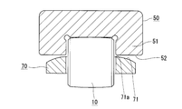
- the cage 70 of the third embodiment has a center of curvature of the guide surface 71 for each side.
- the initial shape of the guide surface 71 is a single arc.
- the guide clearance of the cage 70 changes from a normal value due to the inclination of the cage 70, but is set to the position of the center of curvature and the radius of curvature that can be maintained positively.
- the guide clearance of the normal cage 70 is a cylindrical clearance as shown in FIG. 8 as a radial clearance between the pocket-side end 71 a of the guide surface 71 and the cage guide surface 52. It can be set equivalent to the guide surface.
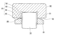
- the guide surface 81 of the cage 80 of the fourth embodiment is a cross section of an arbitrary axial plane, and a plurality of straight lines 82, 83 inclined toward the anti-cage guide surface 52 in the axial direction toward the anti-pocket side.
- the initial shape is formed of 84 and 85.
- the guide surface 81 can be formed without including a curved line bent in the radial direction in the cross section.
- the guide surface 81 can be formed by machining a plurality of conical surfaces having the bearing central axis as the center line so that the small ends of the conical surfaces are directed toward the opposite side in the axial direction.
- Each joint between the straight lines 82 to 85 is located in the same arc shape as the guide surface 71 in FIG. 4, and as is clear from the comparison between FIG. 4 and FIG. 5, the guide surface 81 in FIG. By being approximated to the circular arc shape, wear of the joint at the time of guiding contact with the cage guide surface 52 is prevented.
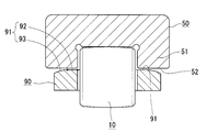
- the guide surface 91 of the cage 90 of the fifth embodiment has a cross section of an arbitrary axial plane, and a straight line 92 in the axial direction and gradually the anti-cage guide as it advances from the straight line 92 toward the non-pocket side in the axial direction. It is formed in an initial shape including a curved line 93 that bends to the surface 52 side. A curved line 93 coincides with the arc shape of the guide surface 71 in FIG. 4, and the guide clearance can be kept positive even when the cage 90 is tilted following the tilt of the cylindrical roller 10. As is clear from the comparison between the guide surface 91 of FIG. 6 and the guide surface 81 of FIG.
- the use of the guide surface 91 including the straight line 92 can reduce the curved curve that is difficult to process in the radial direction.
- the straight line 92 can be formed, for example, by machining a cylindrical surface having the bearing central axis as a center line.
- the joint between the straight line 92 and the curved line 93 is preferably connected smoothly.
- the sixth embodiment will be described with reference to FIG. Hereinafter, points further different from the second embodiment will be described.
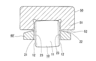
- the cage 60 ′ of the sixth embodiment is obtained by changing only the shape of the pocket width surface portion 23 that guides the end surface 12 of the cylindrical roller 10.
- the pocket width surface portion 23 is formed in a medium-high shape that is highest in the axial direction at the center in the radial direction and gradually decreases as the distance from the center in the radial direction increases.
- the regular axial pocket clearance is set between the center portions of the medium-high radial direction in the pocket width surface portions 23 on both sides.
- the following retainer 60 when the cylindrical roller 10 is tilted, the following retainer 60 'inherently tilts with a delay, so that the edge of the end surface 12 of the cylindrical roller 10 approaches the pocket width surface portion 23 and the pocket clearance decreases in the axial direction. Will behave.
- the decrease in the axial width due to the medium-high shape of the pocket width surface portion 23 is offset. Therefore, it is possible to prevent the pocket width surface portion 23 from being worn by the edge contact of the end surface 12 of the tilted cylindrical roller 10. As a result, the end surface 12 and the pocket width surface portion 23 are prevented from being galled, and further smooth guidance is possible.
- the cylindrical roller 10 can be tilted in the pocket 21, it is effective to prevent the retainer 60 'from being excessively inclined and protruding from the bearing width surface.
- the height difference of the medium-high shape may be appropriately set as long as the pocket clearance in the axial direction can be kept positive even when the allowable inclination angle is reached, and the axial end of the pocket 21 that does not contact the end face 12 of the cylindrical roller 10 is set to the medium-high height. It need not be included in the shape.
- the cylindrical roller of each embodiment can be a needle roller or a rod roller.
- a cylindrical roller bearing having only one raceway surface on the shaft or housing and having a cage guide surface can be provided.
- Each embodiment has been described with an example of an outer ring guide type raceway guide retainer, but can be applied to an inner ring guide type.
- it can replace with the insertion groove part of 1st Embodiment, and can also employ
Landscapes
- Engineering & Computer Science (AREA)
- General Engineering & Computer Science (AREA)
- Mechanical Engineering (AREA)
- Rolling Contact Bearings (AREA)
Abstract
軸及びハウジング間のミスアライメントで円筒ころのチルトに追随した保持器の案内面と、軌道輪のつばの保持器案内面とのエッジ当たりを防止する。保持器(20)の案内面(22)の初期形状を、軌道輪(30)の軌道面(32)の幅中央を通るラジアル平面上かつ軸受中心軸上に中心(O)をもった球面S状とし、つば(31)の保持器案内面(33)の初期形状も相似形の球面状とし、ミスアライメントで許容傾き角θ=0.5°になり、円筒ころ(10)のチルトに追随して保持器(20)が傾いても、案内面(22)の球面S状によるラジアル方向の寸法変化で保持器(20)の案内すきまを正に保てるようにした。
Description
この発明は、円筒ころ軸受に関する。
従来、軸又はハウジングの傾きを許容する転がり軸受として、自動調心ころ軸受が使用されてきた。自動調心ころ軸受は、複列のころを組み込むため、軸受幅が広くなる傾向があり、また、高速回転にも適さない(例えば、特許文献1)。
一方、円筒ころ軸受として、単列の円筒ころを複数のポケットで保持する保持器と、つばが形成された軌道輪とを備えたものがある。円筒ころ軸受は、単列であっても、同じ軸受外径の自動調心ころ軸受に比して負荷容量も大きくすることができ、高速回転への適用性にも優れている。
一般に、転動面が円筒面の円筒ころを採用した円筒ころ軸受では、円筒ころのチルト時にエッジロードの問題があるため、ミスアライメントの許容傾き角が0.001rad~0.005radに設定されている。現在では、円筒ころの転動面に特殊なクラウニングを施す等により、普通荷重における許容傾き角は、自動調心ころ軸受の許容調心角と同等の0.5°(0.009rad)程度に設定することが可能になっている(例えば、特許文献2、非特許文献1)。
NTN TECHNICAL REVIEW No. 75(2007)の第140頁~第148頁
しかしながら、軸又はハウジングの傾きの影響で、これらの間にミスアライメントが生じることがあり、軸受運転中、ミスアライメントで傾く軌道面に追随して円筒ころがチルトを生じ、その円筒ころを受ける保持器もチルトに追随して傾くことがある。図8に示すように、軌道輪100のつば101に円筒面状の保持器案内面102が形成され、保持器110が、保持器案内面102によりラジアル方向に案内される円筒面状の案内面111をもった円筒ころ軸受では、正規の保持器110の案内すきまが小さく設定されている。前記のように自動調心ころ軸受と同等の許容傾き角に設定すると、ミスアライメントに追随する円筒ころ120のチルトに追随して保持器110が傾く挙動で保持器110の案内すきまが0以下に減少し、案内面111の反ポケット側の端(エッジ)が保持器案内面102に強く当って摩耗粉などが発生し得る。このような保持器の傾き挙動は、チルトし易いクラウニングころで顕著だが、ころ中心軸に平行な直線を転動面の母線にもった円筒ころでも起り得る。
そこで、この発明が解決しようとする課題は、ミスアライメントで円筒ころのチルトに追随した保持器の案内面と、つばの保持器案内面とのエッジ当たりを防止することである。
上記の課題を達成するため、この発明は、単列の円筒ころを複数のポケットで保持する保持器と、つばが形成された軌道輪とを備え、前記保持器が、前記つばの保持器案内面によりラジアル方向に案内される案内面を有し、軸とハウジング間のミスアライメントによる前記円筒ころのチルトに追随して、前記保持器が傾く円筒ころ軸受において、前記案内面が、前記円筒ころのチルトに追随した前記保持器の案内すきまを正に保てるラジアル方向の寸法変化をもった初期形状に形成されている構成を採用したものである。ここで、「初期形状」とは、円筒ころ軸受を軸及びハウジング間に最初に組み込んで使用を開始する時点での形状を意味する。円筒ころは、外径面の母線が直線であって、ころ中心軸に平行であるころ、及びクラウニングころのいずれでもよい。
案内面の反ポケット側におけるラジアル方向のドロップ量の分布により、円筒ころのチルトに追随した保持器の傾きに伴う案内すきまの減少を相殺することができる。この分布の決定に際し、保持器の案内すきまを正に保てるラジアル方向の寸法変化をもった案内面の初期形状にしておけば、軸受使用開始当初から、ミスアライメントで保持器案内面と強く当り得るエッジが案内面に存在しない。したがって、保持器案内面と案内面のエッジ当たりが防止される。
前記案内面の具体的な初期形状として、例えば、任意のアキシアル平面の断面で、案内面のポケット側の端からアキシアル方向に反ポケット側の方へ進むに連れて次第に反保持器案内面側に曲がる形状が挙げられる。この形状では、案内面のポケット側の端において、正規の保持器の案内すきまを円筒面状の案内面と同等に設定することができる。
より好ましい初期形状として、前記保持器に存在する全ての前記案内面が、前記軌道輪の軌道面幅中央を通るラジアル平面上かつ軸受中心軸上に中心をもった同一球面に含まれる形状が挙げられる。当該中心回りでどちらに保持器が傾いても、正規の保持器の案内すきまを保つことができる。
さらに好ましくは、前記保持器案内面が、前記案内面と同一の中心をもった球面状の初期形状に形成されているとよい。当該中心回りでどちらに保持器が傾いても、案内面と保持器案内面との案内接触幅の減少を防止することができる。
外輪の内径面の両側に前記つばが形成された外輪案内方式の円筒ころ軸受で、上述のように保持器案内面と案内面を相似の球面状にすると、保持器案内面の最小内径が案内面の最大外径よりも小さくなるので、軸受組立て時、保持器を外輪と同軸のまま外輪の内方に挿入することが困難になる。外輪や保持器を分割構造、例えば1か所割り軌道輪、2つ割り軌道輪にすることで対応可能だが、外輪に保持器用の入れ溝を形成して割り構造を避けることも可能である。
すなわち、前記両側のつばの片側に切欠き状の入れ溝部が形成されており、前記保持器を、前記軌道輪と直角な向きで前記入れ溝部からアキシアル方向に前記つばの奥まで通し、当該軌道輪とラジアル方向に重なるように回転させることができるようにするとよい。前記のラジアル平面上に保持器中心軸が位置するまで保持器を通したところで、保持器を軌道輪とラジアル方向に重なるように回転させ、ポケットを軌道面に臨ませることができる。
この発明では、前記保持器案内面が円筒面状の初期形状に形成されているものであってもよい。上述のようにラジアル方向の寸法変化をもった案内面で案内すきまの確保を図るので、円筒面状の保持器案内面が形成された一般的なつば付き軌道輪をそのまま採用することができる。
前記案内面は球面状以外にも、複数の面を組み合わせた様々な初期形状に形成することができる。
例えば、前記案内面が、任意のアキシアル平面の断面で、アキシアル方向の直線と、当該直線からアキシアル方向に反ポケット側の方へ進むに連れて次第に反保持器案内面側に曲がる曲線とからなる初期形状を採用することができる。加工の難しいラジアル方向に曲がった曲線を直線で減らしつつ、円筒面域の反ポケット側に連なる曲面域により、保持器傾き時も案内すきまを保つことができる。
別例として、前記案内面が、任意のアキシアル平面の断面で、アキシアル方向に反ポケット側の方へ向って反保持器案内面側に傾いた複数の直線からなる初期形状を採用することができる。ラジアル方向に曲がった曲線を含めずに案内面を形成することができる。
前記円筒ころの許容傾き角を大きくする場合、前記保持器が円筒ころに追随して傾くので、アキシアル方向のポケットすきまを定める保持器のポケット幅面部と円筒ころの端面との接触による摩耗を防止することが好ましい。
具体的には、前記円筒ころの端面を案内するポケット幅面部が、任意のアキシアル平面の断面で、ラジアル方向中央でアキシアル方向に最も高く、かつ当該中央からラジアル方向に離れるに連れて次第に低くなる中高形状に形成されているとよい。円筒ころのチルト時、保持器のポケット幅面部の中高形状により、正規のアキシアル方向のポケットすきまからの減少が相殺されるので、チルトした円筒ころの端面のエッジ当たりによるポケット幅面部の摩耗を防止することができる。
この発明は、自動調心ころ軸受と同等のミスアライメントを許容する用途の円筒ころ軸受に採用することができる。例えば、前記ラジアル方向の寸法変化が、前記ミスアライメントがアキシアル方向に対して0.5°のとき、前記案内すきまを正に保てるように設定されていると、普通荷重で自動調心ころ軸受に代用可能な円筒ころ軸受を得ることができる。
前記円筒ころの直径に対する長さ比を問わない。例えば、前記円筒ころが針状ころ又は棒状ころからなるものを採用することもできる。なお、「針状ころ」は、直径に対する長さの比が大きく、直径が小さい円筒ころであって、直径が5mmを超えず、長さがその3~10倍であるものをいう。「棒状ころ」は、直径に対する長さの比が大きく、直径が比較的大きい円筒ころであって、直径が5mmを超え15mm以下で、長さが直径の3~10倍であるものをいう。
上述のように、この発明は、上記構成の採用により、ミスアライメントで円筒ころのチルトに追随した保持器の案内面と、つばの保持器案内面との案内すきまを正に保てるので、これら案内面と保持器案内面のエッジ当たりを防止することができる。
以下、この発明の実施形態を添付図面に基いて説明する。図1に示すように、第1実施形態は、単列の円筒ころ10を複数のポケット21で保持する保持器20と、軌道輪30とを備えた円筒ころ軸受になっている。軌道輪30は、内径面の両側につば31が形成された外輪からなる。
円筒ころ10は、転動面11にクラウニングを施されている。図示では、クラウニングを模式的に描いたが、実際にはラジアル負荷による円筒ころ10の弾性変形により、転動面11は軌道面32の略全幅で線接触することになる。なお、この発明での「ラジアル」、「アキシアル」の概念は、特に言及しない限り、軸受中心軸に基く。
図示例のハウジングhは、軌道輪30を外方から支持している。図示例の軸axは、内方の軌道面41をもった部材40を内方から支持している。図中、軸axとハウジングh間のミスアライメントが0、保持器20及び軌道輪30が軸受中心軸に同軸、かつ円筒ころ10の長さ中央が軌道輪の軌道面32の幅中央を通るラジアル平面上に位置した状態を実線で描いている。また、実線の状態から内方の軌道面41をもった部材40が許容傾き角θになり、円筒ころ10のチルトに追随して保持器20が中心O回りで傾いた状態の主な外形線を二点鎖線で描いている。中心Oは、前記ラジアル平面上かつ軸受中心軸上に位置している。軸axとハウジングh間のミスアライメントが生じると、内外の軌道面41、32の一方の中心軸が他方の中心軸に対して傾くことに伴って、円筒ころ10がチルトする。チルトする円筒ころ10をポケット21の内面で受ける保持器20は、円筒ころ10に捻られるので、円筒ころ10のチルトに追随して傾く。この円筒ころ軸受の許容傾き角θは、自動調心ころ軸受の許容調心角と同等にするため、普通荷重で0.5°に設定されている。普通荷重は、基本動ラジアル荷重Crの0.09倍相当荷重のことをいう。なお、二点鎖線の図示は、各部材の傾きを許容傾き角θよりも誇張して描いている。
つば31に保持器案内面33が形成されている。保持器20は、つば31の保持器案内面33によりラジアル方向に案内される案内面22を有している。案内面22は、保持器20の両側の環状部にそれぞれ形成されている。案内面22の幅及び保持器案内面33の幅は、軸受運転中に保持器20のラジアル方向の位置決めに寄与し得る摺接範囲の全幅で決まる。環状部の幅全体、つば31の幅全体が案内面22等になっている必要はない。許容傾き角θになって保持器20が最大限に傾いても、保持器20のラジアル方向の位置決めに寄与しない環状部の表面部分は案内面22を構成しない。例えば、案内面22の反ポケット側の端22bは、保持器幅面側の面取りのR形状とのつなぎ目になっており、当該面取りは保持器20が最大限に傾いてもラジアル方向の位置決めに寄与しない。なお、クラウニング設計において、普通荷重かつ許容傾き角θのときの円筒ころ10のチルト角度が決まる。許容傾き角θでの保持器20の最大限の傾きの角度は、そのチルト角度の円筒ころ10と保持器20との接触部分の幾何的関係に基いて計算で求めることができる。
案内面22のアキシアル平面の断面での初期形状は、案内面22のポケット21側の端22aからアキシアル方向に反ポケット21側の方へ進むに連れて次第に反保持器案内面33側に曲がる形状になっている。案内面22は、任意のアキシアル平面の断面で、図中と同じ初期形状に形成されている。保持器20は、成型、削り出し等の適宜の加工方法、材料で初期形状に形成すればよい。
保持器20及び軌道輪30はアキシアル方向に対称形になっている。保持器20に存在する全ての案内面22、22は、前記のラジアル平面上かつ軸受中心軸上に中心Oをもった同一球面S(図中に一点鎖線で描く)に含まれる初期形状になっている。一方、保持器案内面33は、案内面22と同一の中心Oをもった球面状の初期形状に形成されている。保持器案内面33は、球面滑り軸受と同様な加工法で加工することが可能である。
保持器20の案内すきまは、幾何的に考えて、軸受中心軸回りの円周方向(以下、単に「円周方向」と呼ぶ)の一箇所で保持器20と軌道輪30とが軸受中心軸に直角な向きに接する位置から、円周方向に180°反対箇所で同向きに接するまで保持器20が自由にラジアル方向に動き得る量に相当する。正規の保持器20の案内すきまは、図中の実線の保持器案内面33及び案内面22の位置関係で設定される。すなわち、保持器案内面33と案内面22とのラジアル方向に対向する任意の二点間において、最小のラジアル方向すきまを2倍した値が正規の保持器の案内すきまに相当する。保持器案内面33及び案内面22が前記のラジアル平面上かつ軸受中心軸上の同一中心Oをもった相似の球面状なので、当該任意の二点間におけるラジアル方向すきまは、どの二点間でも同じ正の値になっている。
図中の二点鎖線で例示したように保持器20が円筒ころ10のチルトに追随する傾きは、円周方向の半周域において案内面22の反ポケット21側の端22bをラジアル方向に軌道輪30の方へ変位させる姿勢変化、すなわち本来、保持器20の案内すきまを減少させる姿勢変化である。案内面22の球面曲率に伴うラジアル方向の寸法変化は、案内面22の端22aから端22bに向って進む程にラジアル方向ドロップ量を大きくするので、その端22bのラジアル方向変位を相殺する。ポケットすきま、及び円筒ころ10とつば31との間に設定されたころ案内すきまがあるため、保持器20のアキシアル振れが発生し得る。前記案内面22のラジアル方向の寸法変化は、保持器20が最大限にアキシアル振れを生じた位置で円筒ころ10のチルトに追随して最大限に傾いても、保持器20の案内すきまを正に保てる、つまり円周方向一箇所で保持器20と軌道輪30とが摺接する案内接触域以外の円周方向領域で案内面22と保持器案内面33間にラジアル方向のすきまが残るように設定されている。したがって、保持器20が円筒ころ10のチルトに追随してどのように傾いても、案内面22の端22bが円周方向二等配箇所で同時に保持器案内面33へ強く当たる摺接状態は生じ得ず、ミスアライメントによる保持器案内面33と案内面22とのエッジ当たりを防止することができる。ひいては、軸受として円滑に回転することができる。
ここで、二点鎖線で例示する如く、保持器20がアキシアル振れ0、かつ軸受中心軸と同軸の状態から中心O回りで傾く場合を見れば分かるように、案内面22の球面性により、案内面22が球面Sに沿って変位するだけなので、前記任意の二点間でラジアル方向すきまが減少する箇所は発生しない。このため、前記最小のラジアル方向すきまは正規の値のままであり、保持器20の案内すきまが変化しない。
この円筒ころ軸受の組立てを説明する。図1、図2に示すように、軌道輪30は、両側のつば31、31の片側に切欠き状の入れ溝部34が形成されている。入れ溝部34は、保持器20の幅より大きい幅をもち、円周方向等配の二箇所に形成されている。保持器20は、軌道輪30と直角な向きで入れ溝部34、34からアキシアル方向につば31の奥まで通される。保持器20の案内面22以外の部分に球面Sから食み出るような肉付けは必要ないので、保持器20は、前記のラジアル平面上に保持器中心軸が位置するまで保持器を通したところで(図2中に二点鎖線で描いた位置)、保持器中心軸及び軸受中心軸に直角な直線回りで回転自在に設けることが可能である。これにより、保持器20を軌道輪30とラジアル方向に重なるように回転させ、図1に示すようにポケット21を軌道面32に臨ませることができる。その後、各ポケット21に内径側からころ入れすれば、軌道輪アセンブリに組み立てることができる。
入れ溝部34を円周方向二等配に形成しているので、各入れ溝部34の深さを浅くすることができる。これにより、図1に示すように、入れ溝部34側のつば31のつば面と、反入れ溝部34側のつば31のつば面とは、実質的に同じラジアル方向長さで円周方向に亘って連なるように形成されているので、円筒ころ10の案内性に支障はない。両側のつば31のいずれに入れ溝部34を形成するかは、円筒ころ軸受のアキシアル負荷用途を考慮して決定すればよい。例えば、アキシアル方向に負荷しない用途のNU形円筒ころ軸受では、どちら側のつば31に入れ溝部34を形成してもよい。NJ形なら、負荷時のころ案内に影響し難い正面側のつば31に形成することが好ましい。上述のように両側のつば31のつば面を円周方向に亘って同様に確保できるならば、NUP形に適用する場合であってもころ案内に支障はない。
第2実施形態を図3に基いて説明する。以下、第1実施形態との相違点を中心に述べ、同一に考えられる構成の説明を省略する。第2実施形態では、軌道輪50のつば51に形成されている保持器案内面52の初期形状が、軸受中心軸を中心軸にもった円筒面状になっている。保持器60の最大外径は、保持器案内面52の径寸よりも小さく、つば51の入れ溝部が省略されている。正規の保持器60の案内すきまは、案内面22のポケット21側の端22aと、保持器案内面52との間のラジアル方向すきまに相当する。球面Sに含まれた案内面22なので、中心O回りに保持器60が傾いても端22aと保持器案内面52との間のラジアル方向すきまの大きさが変化せず、正規の保持器の案内すきまを保つことができる。第2実施形態は、第1実施形態に比して、案内面22と保持器案内面52とが摺接する案内接触幅は少なくなるが、円筒面状の保持器案内面が形成された一般的なつば付き軌道輪をそのまま採用することができる。
第3実施形態を図4に基いて説明する。以下、第2実施形態からさらに相違する点を述べる。第3実施形態の保持器70は、片側ごとに案内面71の曲率中心を定めたものになっている。任意のアキシアル平面の断面で考えると、案内面71の初期形状は、単一の円弧状になっている。この円弧状は、保持器70の傾きによって保持器70の案内すきまは正規の値から変化するが、正には保てる曲率中心の位置及び曲率半径に設定されている。このような形状でも、正規の保持器70の案内すきまは、案内面71のポケット側の端71aと、保持器案内面52との間のラジアル方向すきまとして、図8のような円筒面状の案内面と同等に設定することができる。
第4実施形態を図5に基いて説明する。以下、第3実施形態からさらに相違する点を述べる。第4実施形態の保持器80の案内面81は、任意のアキシアル平面の断面で、アキシアル方向に反ポケット側の方へ向って反保持器案内面52側に傾いた複数の直線82、83、84、85からなる初期形状に形成されている。したがって、第4実施形態は、前記の断面でラジアル方向に曲がった曲線を含めずに案内面81を形成することができる。例えば、軸受中心軸を中心線にもった複数の円すい面を、各円すい面の小端部が軸方向反ポケット側に向くように連ねて加工すれば、案内面81を形成することができる。直線82~85間の各つなぎ目は、図4の案内面71と同じ円弧状に位置し、図4と図5の対比から明らかなように、図5の案内面81を図4の案内面71の円弧状に近似させることにより、保持器案内面52に案内接触する際のつなぎ目の摩耗が防止されている。
第5実施形態を図6に基いて説明する。以下、第3実施形態からさらに相違する点を述べる。第5実施形態の保持器90の案内面91は、任意のアキシアル平面の断面で、アキシアル方向の直線92と、直線92からアキシアル方向に反ポケット側の方へ進むに連れて次第に反保持器案内面52側に曲がる曲線93とからなる初期形状に形成されている。曲線93は、図4の案内面71の円弧状に一致しており、円筒ころ10のチルトに追随した保持器90の傾き時も案内すきまを正に保つことができる。図6の案内面91と図5の案内面81とを対比すれば明らかなように、直線92を含む案内面91の採用により、加工の難しいラジアル方向に曲がった曲線を減らすことができる。直線92は、例えば、軸受中心軸を中心線にもった円筒面の加工によって形成することができる。直線92と曲線93のつなぎ目は、滑らかに連なることが好ましい。
第6実施形態を図7に基いて説明する。以下、第2実施形態からさらに相違する点を述べる。第6実施形態の保持器60’は、円筒ころ10の端面12を案内するポケット幅面部23の形状のみを変更したものである。任意のアキシアル平面の断面で、ポケット幅面部23は、ラジアル方向中央でアキシアル方向に最も高く、かつ当該中央からラジアル方向に離れるに連れて次第に低くなる中高形状に形成されている。正規のアキシアル方向のポケットすきまは、両側のポケット幅面部23のうち、中高形状のラジアル方向中央間で設定されている。図示のように、円筒ころ10のチルト時、本来、追随する保持器60’が遅れて傾くので、円筒ころ10の端面12のエッジがポケット幅面部23に接近し、ポケットすきまがアキシアル方向に減少する挙動になる。ポケット幅面部23の中高形状によるアキシアル方向の高低差により、その減少が相殺される。したがって、チルトした円筒ころ10の端面12のエッジ当たりによるポケット幅面部23の摩耗を防止することができる。ひいては、端面12とポケット幅面部23のかじりを防止し、一層の円滑な案内が可能となる。また、ポケット21内で円筒ころ10がチルトすることができるため、保持器60’が過度に傾いて軸受幅面から突出しないようにするのにも有効である。中高形状の高低差は、許容傾き角になってもアキシアル方向のポケットすきまを正に保てる限り、適宜に設定すればよく、円筒ころ10の端面12に接触しないポケット21のアキシアル方向端部を中高形状に含める必要はない。
この発明の技術的範囲は、上述の実施形態に限定されず、特許請求の範囲の記載に基く技術的思想の範囲内での全ての変更を含むものである。例えば、各実施形態の円筒ころを針状ころ又は棒状ころにすることもできる。針状ころにする場合、軸又はハウジングに一方の軌道面を形成し、保持器案内面をもった軌道輪のみを備えた円筒ころ軸受にすることもできる。また、各実施形態を外輪案内方式の軌道輪案内保持器の例で説明したが、内輪案内方式に適用することができる。また、第1実施形態の入れ溝部に代えて、二つ割り外輪を採用し、外輪をプランマブロックで固定する組立てを採用することもできる。
10 円筒ころ
11 転動面
12 端面
20、60、60’、70、80、90 保持器
21 ポケット
22、71、81、91 案内面
22a、71a ポケット側の端
22b 反ポケット側の端
23 ポケット幅面部
30、50 軌道輪
31、51 つば
32 軌道面
33、52 保持器案内面
34 入れ溝部
82、83、84、85、92 直線
93 曲線
S 球面
O 中心
11 転動面
12 端面
20、60、60’、70、80、90 保持器
21 ポケット
22、71、81、91 案内面
22a、71a ポケット側の端
22b 反ポケット側の端
23 ポケット幅面部
30、50 軌道輪
31、51 つば
32 軌道面
33、52 保持器案内面
34 入れ溝部
82、83、84、85、92 直線
93 曲線
S 球面
O 中心
Claims (11)
- 単列の円筒ころを複数のポケットで保持する保持器と、つばが形成された軌道輪とを備え、
前記保持器が、前記つばの保持器案内面によりラジアル方向に案内される案内面を有し、
軸とハウジング間のミスアライメントによる前記円筒ころのチルトに追随して、前記保持器が傾く円筒ころ軸受において、
前記案内面が、前記円筒ころのチルトに追随した前記保持器の案内すきまを正に保てるラジアル方向の寸法変化をもった初期形状に形成されていることを特徴とする円筒ころ軸受。 - 前記案内面が、任意のアキシアル平面の断面で、前記案内面のポケット側の端からアキシアル方向に反ポケット側の方へ進むに連れて次第に反保持器案内面側に曲がる初期形状に形成されている請求項1に記載の円筒ころ軸受。
- 前記保持器に存在する全ての前記案内面が、前記軌道輪の軌道面幅中央を通るラジアル平面上かつ軸受中心軸上に中心をもった同一球面に含まれる初期形状に形成されている請求項2に記載の円筒ころ軸受。
- 前記保持器案内面が、前記案内面と同一の中心をもった球面状の初期形状に形成されている請求項3に記載の円筒ころ軸受。
- 前記軌道輪が、内径面の両側に前記つばをもった外輪からなり、
前記両側のつばの片側に切欠き状の入れ溝部が形成されており、
前記保持器を、前記軌道輪と直角な向きで前記入れ溝部からアキシアル方向に前記つばの奥まで通し、当該軌道輪とラジアル方向に重なるように回転させることができる請求項4に記載の円筒ころ軸受。 - 前記保持器案内面が円筒面状の初期形状に形成されている請求項3に記載の円筒ころ軸受。
- 前記案内面が、任意のアキシアル平面の断面で、アキシアル方向の直線と、当該直線からアキシアル方向に反ポケット側の方へ進むに連れて次第に反保持器案内面側に曲がる曲線とからなる初期形状に形成されている請求項1に記載の円筒ころ軸受。
- 前記案内面が、任意のアキシアル平面の断面で、アキシアル方向に反ポケット側の方へ向って反保持器案内面側に傾いた複数の直線からなる初期形状に形成されている請求項1に記載の円筒ころ軸受。
- 前記円筒ころの端面を案内するポケット幅面部が、任意のアキシアル平面の断面で、ラジアル方向中央でアキシアル方向に最も高く、かつ当該中央からラジアル方向に離れるに連れて次第に低くなる中高形状に形成されている請求項1から8のいずれか1項に記載の円筒ころ軸受。
- 前記ラジアル方向の寸法変化が、前記ミスアライメントがアキシアル方向に対して0.5°のとき、前記案内すきまを正に保てるように設定されている請求項1から9のいずれか1項に記載の円筒ころ軸受。
- 前記円筒ころが、針状ころ又は棒状ころからなる請求項1から10のいずれか1項に記載の円筒ころ軸受。
Applications Claiming Priority (2)
| Application Number | Priority Date | Filing Date | Title |
|---|---|---|---|
| JP2011-135005 | 2011-06-17 | ||
| JP2011135005A JP2013002567A (ja) | 2011-06-17 | 2011-06-17 | 円筒ころ軸受 |
Publications (1)
| Publication Number | Publication Date |
|---|---|
| WO2012173046A1 true WO2012173046A1 (ja) | 2012-12-20 |
Family
ID=47357035
Family Applications (1)
| Application Number | Title | Priority Date | Filing Date |
|---|---|---|---|
| PCT/JP2012/064747 Ceased WO2012173046A1 (ja) | 2011-06-17 | 2012-06-08 | 円筒ころ軸受 |
Country Status (2)
| Country | Link |
|---|---|
| JP (1) | JP2013002567A (ja) |
| WO (1) | WO2012173046A1 (ja) |
Cited By (3)
| Publication number | Priority date | Publication date | Assignee | Title |
|---|---|---|---|---|
| JP2014202253A (ja) * | 2013-04-03 | 2014-10-27 | 株式会社ジェイテクト | 複列ころ軸受用の櫛型保持器及び複列ころ軸受 |
| GB2545064A (en) * | 2015-11-11 | 2017-06-07 | Rolls Royce Plc | A bearing arrangement and a bearing cage |
| JP2018021678A (ja) * | 2013-01-31 | 2018-02-08 | 日本精工株式会社 | 円筒ころ軸受 |
Citations (5)
| Publication number | Priority date | Publication date | Assignee | Title |
|---|---|---|---|---|
| JPS6245420U (ja) * | 1985-09-06 | 1987-03-19 | ||
| JPH0712132A (ja) * | 1993-06-28 | 1995-01-17 | Nippon Seiko Kk | 転がり軸受 |
| JP2005090657A (ja) * | 2003-09-18 | 2005-04-07 | Nsk Ltd | 転がり軸受用保持器及び該保持器を組み込んだ転がり軸受 |
| JP2007292153A (ja) * | 2006-04-24 | 2007-11-08 | Nsk Ltd | ラジアル針状ころ軸受 |
| JP2008121769A (ja) * | 2006-11-10 | 2008-05-29 | Ntn Corp | ころ軸受のクラウニングの設計方法 |
-
2011
- 2011-06-17 JP JP2011135005A patent/JP2013002567A/ja not_active Withdrawn
-
2012
- 2012-06-08 WO PCT/JP2012/064747 patent/WO2012173046A1/ja not_active Ceased
Patent Citations (5)
| Publication number | Priority date | Publication date | Assignee | Title |
|---|---|---|---|---|
| JPS6245420U (ja) * | 1985-09-06 | 1987-03-19 | ||
| JPH0712132A (ja) * | 1993-06-28 | 1995-01-17 | Nippon Seiko Kk | 転がり軸受 |
| JP2005090657A (ja) * | 2003-09-18 | 2005-04-07 | Nsk Ltd | 転がり軸受用保持器及び該保持器を組み込んだ転がり軸受 |
| JP2007292153A (ja) * | 2006-04-24 | 2007-11-08 | Nsk Ltd | ラジアル針状ころ軸受 |
| JP2008121769A (ja) * | 2006-11-10 | 2008-05-29 | Ntn Corp | ころ軸受のクラウニングの設計方法 |
Cited By (5)
| Publication number | Priority date | Publication date | Assignee | Title |
|---|---|---|---|---|
| JP2018021678A (ja) * | 2013-01-31 | 2018-02-08 | 日本精工株式会社 | 円筒ころ軸受 |
| JP2014202253A (ja) * | 2013-04-03 | 2014-10-27 | 株式会社ジェイテクト | 複列ころ軸受用の櫛型保持器及び複列ころ軸受 |
| GB2545064A (en) * | 2015-11-11 | 2017-06-07 | Rolls Royce Plc | A bearing arrangement and a bearing cage |
| GB2545064B (en) * | 2015-11-11 | 2018-02-21 | Rolls Royce Plc | A bearing arrangement and a bearing cage |
| US9951814B2 (en) | 2015-11-11 | 2018-04-24 | Rolls-Royce Plc | Bearing arrangement and a bearing cage |
Also Published As
| Publication number | Publication date |
|---|---|
| JP2013002567A (ja) | 2013-01-07 |
Similar Documents
| Publication | Publication Date | Title |
|---|---|---|
| US8985860B2 (en) | Prong type resin cage for double row roller bearing and double row roller bearing | |
| JP5613649B2 (ja) | クロスローラー軸受 | |
| JPS58134222A (ja) | 1列あるいは4列テ−パころ軸受 | |
| WO2013080824A1 (ja) | ころ軸受 | |
| US20160025134A1 (en) | Cage for angular ball bearing | |
| JP4803031B2 (ja) | 自動調心ころ軸受用保持器の製造方法 | |
| WO2012173046A1 (ja) | 円筒ころ軸受 | |
| JP6544000B2 (ja) | 自動調心ころ軸受 | |
| JP2006112555A (ja) | 調心輪付きころ軸受 | |
| JP5929481B2 (ja) | 自動調心ころ軸受及び回転機器 | |
| JP2008133894A (ja) | 玉軸受用保持器 | |
| WO2018225720A1 (ja) | 転がり軸受用保持器および転がり軸受 | |
| US20180112715A1 (en) | Rolling Bearing | |
| JP6696610B2 (ja) | 転がり軸受用かご型保持器 | |
| JP2010025191A (ja) | 自動調心ころ軸受 | |
| JP2023160080A (ja) | 自動調心ころ軸受 | |
| JP2007278406A (ja) | 保持器付ころ軸受 | |
| CN114641622B (zh) | 三叉型等速接头 | |
| JP2014043900A (ja) | 転がり軸受 | |
| JP4457601B2 (ja) | シェル型ニードル軸受 | |
| JP2020169663A (ja) | 自動調心ころ軸受 | |
| JP2020159498A (ja) | クロスローラ軸受 | |
| JP7259402B2 (ja) | スラストころ軸受 | |
| JP2009210091A (ja) | 自動調心ころ軸受 | |
| JP6859877B2 (ja) | 自動調心ころ軸受 |
Legal Events
| Date | Code | Title | Description |
|---|---|---|---|
| 121 | Ep: the epo has been informed by wipo that ep was designated in this application |
Ref document number: 12799772 Country of ref document: EP Kind code of ref document: A1 |
|
| NENP | Non-entry into the national phase |
Ref country code: DE |
|
| 122 | Ep: pct application non-entry in european phase |
Ref document number: 12799772 Country of ref document: EP Kind code of ref document: A1 |