WO2012172716A1 - コルゲートフィン式熱交換器の排水構造 - Google Patents
コルゲートフィン式熱交換器の排水構造 Download PDFInfo
- Publication number
- WO2012172716A1 WO2012172716A1 PCT/JP2012/002257 JP2012002257W WO2012172716A1 WO 2012172716 A1 WO2012172716 A1 WO 2012172716A1 JP 2012002257 W JP2012002257 W JP 2012002257W WO 2012172716 A1 WO2012172716 A1 WO 2012172716A1
- Authority
- WO
- WIPO (PCT)
- Prior art keywords
- heat exchanger
- corrugated fin
- corrugated
- drainage structure
- cut
- Prior art date
- Legal status (The legal status is an assumption and is not a legal conclusion. Google has not performed a legal analysis and makes no representation as to the accuracy of the status listed.)
- Ceased
Links
Images


Classifications
-
- F—MECHANICAL ENGINEERING; LIGHTING; HEATING; WEAPONS; BLASTING
- F28—HEAT EXCHANGE IN GENERAL
- F28D—HEAT-EXCHANGE APPARATUS, NOT PROVIDED FOR IN ANOTHER SUBCLASS, IN WHICH THE HEAT-EXCHANGE MEDIA DO NOT COME INTO DIRECT CONTACT
- F28D1/00—Heat-exchange apparatus having stationary conduit assemblies for one heat-exchange medium only, the media being in contact with different sides of the conduit wall, in which the other heat-exchange medium is a large body of fluid, e.g. domestic or motor car radiators
- F28D1/02—Heat-exchange apparatus having stationary conduit assemblies for one heat-exchange medium only, the media being in contact with different sides of the conduit wall, in which the other heat-exchange medium is a large body of fluid, e.g. domestic or motor car radiators with heat-exchange conduits immersed in the body of fluid
- F28D1/04—Heat-exchange apparatus having stationary conduit assemblies for one heat-exchange medium only, the media being in contact with different sides of the conduit wall, in which the other heat-exchange medium is a large body of fluid, e.g. domestic or motor car radiators with heat-exchange conduits immersed in the body of fluid with tubular conduits
- F28D1/053—Heat-exchange apparatus having stationary conduit assemblies for one heat-exchange medium only, the media being in contact with different sides of the conduit wall, in which the other heat-exchange medium is a large body of fluid, e.g. domestic or motor car radiators with heat-exchange conduits immersed in the body of fluid with tubular conduits the conduits being straight
- F28D1/0535—Heat-exchange apparatus having stationary conduit assemblies for one heat-exchange medium only, the media being in contact with different sides of the conduit wall, in which the other heat-exchange medium is a large body of fluid, e.g. domestic or motor car radiators with heat-exchange conduits immersed in the body of fluid with tubular conduits the conduits being straight the conduits having a non-circular cross-section
- F28D1/05366—Assemblies of conduits connected to common headers, e.g. core type radiators
- F28D1/05383—Assemblies of conduits connected to common headers, e.g. core type radiators with multiple rows of conduits or with multi-channel conduits
-
- F—MECHANICAL ENGINEERING; LIGHTING; HEATING; WEAPONS; BLASTING
- F25—REFRIGERATION OR COOLING; COMBINED HEATING AND REFRIGERATION SYSTEMS; HEAT PUMP SYSTEMS; MANUFACTURE OR STORAGE OF ICE; LIQUEFACTION SOLIDIFICATION OF GASES
- F25D—REFRIGERATORS; COLD ROOMS; ICE-BOXES; COOLING OR FREEZING APPARATUS NOT OTHERWISE PROVIDED FOR
- F25D21/00—Defrosting; Preventing frosting; Removing condensed or defrost water
- F25D21/14—Collecting or removing condensed and defrost water; Drip trays
-
- F—MECHANICAL ENGINEERING; LIGHTING; HEATING; WEAPONS; BLASTING
- F28—HEAT EXCHANGE IN GENERAL
- F28F—DETAILS OF HEAT-EXCHANGE AND HEAT-TRANSFER APPARATUS, OF GENERAL APPLICATION
- F28F1/00—Tubular elements; Assemblies of tubular elements
- F28F1/10—Tubular elements and assemblies thereof with means for increasing heat-transfer area, e.g. with fins, with projections, with recesses
- F28F1/12—Tubular elements and assemblies thereof with means for increasing heat-transfer area, e.g. with fins, with projections, with recesses the means being only outside the tubular element
- F28F1/126—Tubular elements and assemblies thereof with means for increasing heat-transfer area, e.g. with fins, with projections, with recesses the means being only outside the tubular element consisting of zig-zag shaped fins
- F28F1/128—Fins with openings, e.g. louvered fins
-
- F—MECHANICAL ENGINEERING; LIGHTING; HEATING; WEAPONS; BLASTING
- F28—HEAT EXCHANGE IN GENERAL
- F28F—DETAILS OF HEAT-EXCHANGE AND HEAT-TRANSFER APPARATUS, OF GENERAL APPLICATION
- F28F17/00—Removing ice or water from heat-exchange apparatus
- F28F17/005—Means for draining condensates from heat exchangers, e.g. from evaporators
-
- F—MECHANICAL ENGINEERING; LIGHTING; HEATING; WEAPONS; BLASTING
- F25—REFRIGERATION OR COOLING; COMBINED HEATING AND REFRIGERATION SYSTEMS; HEAT PUMP SYSTEMS; MANUFACTURE OR STORAGE OF ICE; LIQUEFACTION SOLIDIFICATION OF GASES
- F25B—REFRIGERATION MACHINES, PLANTS OR SYSTEMS; COMBINED HEATING AND REFRIGERATION SYSTEMS; HEAT PUMP SYSTEMS
- F25B2500/00—Problems to be solved
- F25B2500/01—Geometry problems, e.g. for reducing size
-
- F—MECHANICAL ENGINEERING; LIGHTING; HEATING; WEAPONS; BLASTING
- F25—REFRIGERATION OR COOLING; COMBINED HEATING AND REFRIGERATION SYSTEMS; HEAT PUMP SYSTEMS; MANUFACTURE OR STORAGE OF ICE; LIQUEFACTION SOLIDIFICATION OF GASES
- F25B—REFRIGERATION MACHINES, PLANTS OR SYSTEMS; COMBINED HEATING AND REFRIGERATION SYSTEMS; HEAT PUMP SYSTEMS
- F25B39/00—Evaporators; Condensers
- F25B39/02—Evaporators
- F25B39/022—Evaporators with plate-like or laminated elements
-
- F—MECHANICAL ENGINEERING; LIGHTING; HEATING; WEAPONS; BLASTING
- F28—HEAT EXCHANGE IN GENERAL
- F28F—DETAILS OF HEAT-EXCHANGE AND HEAT-TRANSFER APPARATUS, OF GENERAL APPLICATION
- F28F1/00—Tubular elements; Assemblies of tubular elements
- F28F1/10—Tubular elements and assemblies thereof with means for increasing heat-transfer area, e.g. with fins, with projections, with recesses
- F28F1/12—Tubular elements and assemblies thereof with means for increasing heat-transfer area, e.g. with fins, with projections, with recesses the means being only outside the tubular element
- F28F1/24—Tubular elements and assemblies thereof with means for increasing heat-transfer area, e.g. with fins, with projections, with recesses the means being only outside the tubular element and extending transversely
- F28F1/26—Tubular elements and assemblies thereof with means for increasing heat-transfer area, e.g. with fins, with projections, with recesses the means being only outside the tubular element and extending transversely the means being integral with the element
Definitions
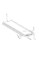
- the corrugated fin heat exchanger drainage structure of the present invention has a plurality of flat heat exchange tubes parallel to each other between a pair of opposing header pipes in a horizontal direction. Corrugated fins formed by alternately repeating valley folds are joined between the heat exchange tubes, and the ridges extending at the ends in the width direction of the heat exchange tubes are cut and raised in an inclined manner.
- a corrugated fin type heat exchanger in which a flow channel is formed by a piece, a plurality of the cut and raised pieces formed on each heat exchange tube are appropriately spaced along the longitudinal direction of the heat exchange tube.
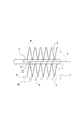
- heat exchange performance can be improved by providing the fin louver 4a in the corrugated fin 4, that is, by providing a predetermined number of louvers formed at a predetermined angle in the air passage, heat transfer performance due to the turbulent flow effect or the like. Can be improved.
- a four-step evaluation test was conducted: good ( ⁇ ), good drainage ( ⁇ ), drainage function but slow speed ( ⁇ ), poor drainage, or impossibility (x). As a result, the results shown in Table 1 were obtained.
- the fin pitch (P) is preferably about 1.6 mm.
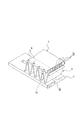
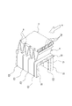
- the condensed water (condensed water) condensed on the surface of the corrugated fins 4 and forming water droplets is sequentially discharged to the corrugated fins 4 on the lower side.
- at least one cut and raised piece 8 is arranged for one mountain of the corrugated fin 4, and smooth drainage is possible. Thereby, even when the flat heat exchange tube 3 is horizontally arranged, the drainage speed can be increased, and the drainage performance can be improved.
Landscapes
- Engineering & Computer Science (AREA)
- Physics & Mathematics (AREA)
- Thermal Sciences (AREA)
- Mechanical Engineering (AREA)
- General Engineering & Computer Science (AREA)
- Geometry (AREA)
- Chemical & Material Sciences (AREA)
- Combustion & Propulsion (AREA)
- Heat-Exchange Devices With Radiators And Conduit Assemblies (AREA)
Priority Applications (3)
| Application Number | Priority Date | Filing Date | Title |
|---|---|---|---|
| CN201280029329.XA CN103797326B (zh) | 2011-06-16 | 2012-04-02 | 波纹片式热交换器的排水结构 |
| US14/125,736 US9423184B2 (en) | 2011-06-16 | 2012-04-02 | Drainage structure for corrugated-fin heat exchanger |
| KR1020147000841A KR101525749B1 (ko) | 2011-06-16 | 2012-04-02 | 코러게이트핀식 열교환기의 배수 구조 |
Applications Claiming Priority (2)
| Application Number | Priority Date | Filing Date | Title |
|---|---|---|---|
| JP2011-134034 | 2011-06-16 | ||
| JP2011134034A JP5678392B2 (ja) | 2011-06-16 | 2011-06-16 | コルゲートフィン式熱交換器の排水構造 |
Publications (1)
| Publication Number | Publication Date |
|---|---|
| WO2012172716A1 true WO2012172716A1 (ja) | 2012-12-20 |
Family
ID=47356737
Family Applications (1)
| Application Number | Title | Priority Date | Filing Date |
|---|---|---|---|
| PCT/JP2012/002257 Ceased WO2012172716A1 (ja) | 2011-06-16 | 2012-04-02 | コルゲートフィン式熱交換器の排水構造 |
Country Status (5)
| Country | Link |
|---|---|
| US (1) | US9423184B2 (enExample) |
| JP (1) | JP5678392B2 (enExample) |
| KR (1) | KR101525749B1 (enExample) |
| CN (1) | CN103797326B (enExample) |
| WO (1) | WO2012172716A1 (enExample) |
Cited By (4)
| Publication number | Priority date | Publication date | Assignee | Title |
|---|---|---|---|---|
| WO2014103268A1 (ja) * | 2012-12-26 | 2014-07-03 | 日本軽金属株式会社 | 熱交換器における熱交換チューブ及び熱交換チューブの製造方法 |
| WO2016027811A1 (ja) * | 2014-08-22 | 2016-02-25 | 日本軽金属株式会社 | フィン・アンド・チューブ型熱交換器 |
| US20170030662A1 (en) * | 2015-07-31 | 2017-02-02 | Lg Electronics Inc. | Heat exchanger |
| WO2021013964A1 (de) * | 2019-07-23 | 2021-01-28 | Bundy Refrigeration Gmbh | Extrudierter flügelrohrabschnitt, flügelrohr mit extrudiertem flügelrohrabschnitt und wärmetauscher mit flügelrohr sowie herstellungsverfahren eines flügelrohrabschnitts |
Families Citing this family (9)
| Publication number | Priority date | Publication date | Assignee | Title |
|---|---|---|---|---|
| US20150144309A1 (en) * | 2013-03-13 | 2015-05-28 | Brayton Energy, Llc | Flattened Envelope Heat Exchanger |
| CN104236332A (zh) * | 2014-08-27 | 2014-12-24 | 杭州三花微通道换热器有限公司 | 换热器 |
| US10309730B2 (en) * | 2015-06-16 | 2019-06-04 | Hamilton Sundstrand Corporation | Mini-channel heat exchanger tube sleeve |
| CN106802029B (zh) * | 2015-11-25 | 2020-04-07 | 杭州三花微通道换热器有限公司 | 换热器芯体和具有它的换热器 |
| CN108253834A (zh) * | 2016-12-28 | 2018-07-06 | 丹佛斯微通道换热器(嘉兴)有限公司 | 用于换热器的扁管和具有该扁管的换热器 |
| CN107747801A (zh) * | 2017-06-05 | 2018-03-02 | 梁世欢 | 显热空气热交换器 |
| CN111256393A (zh) * | 2018-11-30 | 2020-06-09 | 杭州三花研究院有限公司 | 翅片及换热器 |
| CN214582619U (zh) * | 2020-12-30 | 2021-11-02 | 丹佛斯有限公司 | 换热器 |
| EP4308870A4 (en) | 2021-03-19 | 2025-03-12 | Brazeway, Inc. | Microchannel heat exchanger for appliance condenser |
Citations (2)
| Publication number | Priority date | Publication date | Assignee | Title |
|---|---|---|---|---|
| JP2010025477A (ja) * | 2008-07-22 | 2010-02-04 | Daikin Ind Ltd | 熱交換器 |
| WO2010106757A1 (ja) * | 2009-03-17 | 2010-09-23 | 日本軽金属株式会社 | コルゲートフィン式熱交換器の排水構造 |
Family Cites Families (11)
| Publication number | Priority date | Publication date | Assignee | Title |
|---|---|---|---|---|
| JPH0664309B2 (ja) * | 1986-03-04 | 1994-08-22 | コニカ株式会社 | ハロゲン化銀溶剤の存在下で増感処理するハロゲン化銀感光材料 |
| JPH0755380A (ja) * | 1993-06-07 | 1995-03-03 | Nippondenso Co Ltd | 熱交換器 |
| KR20040017920A (ko) * | 2002-08-22 | 2004-03-02 | 엘지전자 주식회사 | 열교환기의 응축수 배출장치 |
| US20080314076A1 (en) * | 2004-06-15 | 2008-12-25 | Showa Denko K.K. | Heat Exchanger |
| JP2007183029A (ja) * | 2006-01-05 | 2007-07-19 | T Rad Co Ltd | 潜熱回収用熱交換器 |
| CN100523696C (zh) * | 2007-04-28 | 2009-08-05 | 珠海格力电器股份有限公司 | 热泵用换热器 |
| JP5320846B2 (ja) * | 2008-06-20 | 2013-10-23 | ダイキン工業株式会社 | 熱交換器 |
| US20100006276A1 (en) * | 2008-07-11 | 2010-01-14 | Johnson Controls Technology Company | Multichannel Heat Exchanger |
| JP2010019534A (ja) * | 2008-07-14 | 2010-01-28 | Daikin Ind Ltd | 熱交換器 |
| JP5550106B2 (ja) * | 2009-03-17 | 2014-07-16 | 日本軽金属株式会社 | コルゲートフィン式熱交換器の排水構造 |
| JP5402159B2 (ja) * | 2009-03-31 | 2014-01-29 | ダイキン工業株式会社 | 空気熱交換器 |
-
2011
- 2011-06-16 JP JP2011134034A patent/JP5678392B2/ja active Active
-
2012
- 2012-04-02 KR KR1020147000841A patent/KR101525749B1/ko not_active Expired - Fee Related
- 2012-04-02 CN CN201280029329.XA patent/CN103797326B/zh active Active
- 2012-04-02 WO PCT/JP2012/002257 patent/WO2012172716A1/ja not_active Ceased
- 2012-04-02 US US14/125,736 patent/US9423184B2/en active Active
Patent Citations (2)
| Publication number | Priority date | Publication date | Assignee | Title |
|---|---|---|---|---|
| JP2010025477A (ja) * | 2008-07-22 | 2010-02-04 | Daikin Ind Ltd | 熱交換器 |
| WO2010106757A1 (ja) * | 2009-03-17 | 2010-09-23 | 日本軽金属株式会社 | コルゲートフィン式熱交換器の排水構造 |
Cited By (6)
| Publication number | Priority date | Publication date | Assignee | Title |
|---|---|---|---|---|
| WO2014103268A1 (ja) * | 2012-12-26 | 2014-07-03 | 日本軽金属株式会社 | 熱交換器における熱交換チューブ及び熱交換チューブの製造方法 |
| JP2014126240A (ja) * | 2012-12-26 | 2014-07-07 | Nippon Light Metal Co Ltd | 熱交換器における熱交換チューブ及び熱交換チューブの製造方法 |
| WO2016027811A1 (ja) * | 2014-08-22 | 2016-02-25 | 日本軽金属株式会社 | フィン・アンド・チューブ型熱交換器 |
| JP2016044895A (ja) * | 2014-08-22 | 2016-04-04 | 日本軽金属株式会社 | フィン・アンド・チューブ型熱交換器 |
| US20170030662A1 (en) * | 2015-07-31 | 2017-02-02 | Lg Electronics Inc. | Heat exchanger |
| WO2021013964A1 (de) * | 2019-07-23 | 2021-01-28 | Bundy Refrigeration Gmbh | Extrudierter flügelrohrabschnitt, flügelrohr mit extrudiertem flügelrohrabschnitt und wärmetauscher mit flügelrohr sowie herstellungsverfahren eines flügelrohrabschnitts |
Also Published As
| Publication number | Publication date |
|---|---|
| JP2013002729A (ja) | 2013-01-07 |
| US9423184B2 (en) | 2016-08-23 |
| JP5678392B2 (ja) | 2015-03-04 |
| CN103797326A (zh) | 2014-05-14 |
| US20140109609A1 (en) | 2014-04-24 |
| CN103797326B (zh) | 2016-01-20 |
| KR101525749B1 (ko) | 2015-06-03 |
| KR20140040221A (ko) | 2014-04-02 |
Similar Documents
| Publication | Publication Date | Title |
|---|---|---|
| JP5678392B2 (ja) | コルゲートフィン式熱交換器の排水構造 | |
| EP2857785B1 (en) | Heat exchanger and air conditioner | |
| AU2009261466B2 (en) | Heat exchanger | |
| JP5550106B2 (ja) | コルゲートフィン式熱交換器の排水構造 | |
| EP2410266B1 (en) | Drainage structure of corrugated fin-type heat exchanger | |
| CN208254300U (zh) | 带有错位翅片的换热器盘管 | |
| CN103492826B (zh) | 热交换器 | |
| CN106918261B (zh) | 一种翅片及热交换器 | |
| JP6330577B2 (ja) | フィン・アンド・チューブ型熱交換器 | |
| JP6375897B2 (ja) | 熱交換器 | |
| WO2013157212A1 (ja) | フィンチューブ熱交換器 | |
| JP5946217B2 (ja) | 熱交換器における熱交換チューブ及び熱交換チューブの製造方法 | |
| JP2009270792A (ja) | 熱交換器 | |
| CN110741217A (zh) | 热交换器和波纹翅片 | |
| CN113357937A (zh) | 翅片及换热器 | |
| JP2012251719A (ja) | コルゲートフィン式熱交換器の排水構造 | |
| JPH0545474U (ja) | 熱交換器 | |
| JP2016188708A (ja) | コルゲートフィン式熱交換器の排水構造 | |
| JP2019045033A (ja) | コルゲートフィン式熱交換器 | |
| JP2012083070A (ja) | コルゲートフィン式熱交換器の排水構造 | |
| JPH1123179A (ja) | フィン付熱交換器 | |
| JP2019045032A (ja) | コルゲートフィン式熱交換器 | |
| CN103791660B (zh) | 翅片管热交换器 | |
| JP2004270959A (ja) | 熱交換器 | |
| JP2019045031A (ja) | コルゲートフィン式熱交換器 |
Legal Events
| Date | Code | Title | Description |
|---|---|---|---|
| 121 | Ep: the epo has been informed by wipo that ep was designated in this application |
Ref document number: 12801092 Country of ref document: EP Kind code of ref document: A1 |
|
| WWE | Wipo information: entry into national phase |
Ref document number: 14125736 Country of ref document: US |
|
| NENP | Non-entry into the national phase |
Ref country code: DE |
|
| ENP | Entry into the national phase |
Ref document number: 20147000841 Country of ref document: KR Kind code of ref document: A |
|
| 122 | Ep: pct application non-entry in european phase |
Ref document number: 12801092 Country of ref document: EP Kind code of ref document: A1 |