WO2012172615A1 - 投射型映像表示装置 - Google Patents
投射型映像表示装置 Download PDFInfo
- Publication number
- WO2012172615A1 WO2012172615A1 PCT/JP2011/003459 JP2011003459W WO2012172615A1 WO 2012172615 A1 WO2012172615 A1 WO 2012172615A1 JP 2011003459 W JP2011003459 W JP 2011003459W WO 2012172615 A1 WO2012172615 A1 WO 2012172615A1
- Authority
- WO
- WIPO (PCT)
- Prior art keywords
- light
- lens
- image display
- display element
- optical system
- Prior art date
- Legal status (The legal status is an assumption and is not a legal conclusion. Google has not performed a legal analysis and makes no representation as to the accuracy of the status listed.)
- Ceased
Links
Images


Classifications
-
- G—PHYSICS
- G03—PHOTOGRAPHY; CINEMATOGRAPHY; ANALOGOUS TECHNIQUES USING WAVES OTHER THAN OPTICAL WAVES; ELECTROGRAPHY; HOLOGRAPHY
- G03B—APPARATUS OR ARRANGEMENTS FOR TAKING PHOTOGRAPHS OR FOR PROJECTING OR VIEWING THEM; APPARATUS OR ARRANGEMENTS EMPLOYING ANALOGOUS TECHNIQUES USING WAVES OTHER THAN OPTICAL WAVES; ACCESSORIES THEREFOR
- G03B21/00—Projectors or projection-type viewers; Accessories therefor
- G03B21/14—Details
- G03B21/16—Cooling; Preventing overheating
-
- H—ELECTRICITY
- H04—ELECTRIC COMMUNICATION TECHNIQUE
- H04N—PICTORIAL COMMUNICATION, e.g. TELEVISION
- H04N9/00—Details of colour television systems
- H04N9/12—Picture reproducers
- H04N9/31—Projection devices for colour picture display, e.g. using electronic spatial light modulators [ESLM]
- H04N9/3102—Projection devices for colour picture display, e.g. using electronic spatial light modulators [ESLM] using two-dimensional electronic spatial light modulators
- H04N9/3105—Projection devices for colour picture display, e.g. using electronic spatial light modulators [ESLM] using two-dimensional electronic spatial light modulators for displaying all colours simultaneously, e.g. by using two or more electronic spatial light modulators
-
- H—ELECTRICITY
- H04—ELECTRIC COMMUNICATION TECHNIQUE
- H04N—PICTORIAL COMMUNICATION, e.g. TELEVISION
- H04N9/00—Details of colour television systems
- H04N9/12—Picture reproducers
- H04N9/31—Projection devices for colour picture display, e.g. using electronic spatial light modulators [ESLM]
- H04N9/3141—Constructional details thereof
- H04N9/3144—Cooling systems
Definitions
- the present invention relates to a projection type video display.
- a sirocco fan is disposed at one end of the side surface of the liquid crystal panel arranged in three planes of the color combining prism, and a light valve including R (B) ⁇ G ⁇ B (R) and a liquid crystal panel and a polarizing plate.
- an object of the present invention is to provide a compact and thin projection type image display apparatus excellent in portability and portability while improving the cooling performance of the liquid crystal panel.
- the projection type image display apparatus separates the color of the light from the light collecting lens, the lens array for dividing the light emitted from the light source into a plurality of light beams, the light collecting lens for collecting the light from the lens array
- a cooling fan comprising: a color separation optical system; an image display element for forming an optical image from light separated by the color separation optical system; a projection lens for projecting an optical image; and a cooling fan for cooling the image display element
- the cooling air which is sent out is supplied to the image display element through the path formed in the light passing area of the color separation optical system.
- the figure which shows the optical system of a projection type video display apparatus The figure which shows the ventilation path of an image display element.
- FIG. 1 is a view showing an optical system of a projection type video display device.
- Reference numeral 1 denotes a light source, which is a white lamp such as an ultra-high pressure mercury lamp, a metal halide lamp, a xenon lamp, a mercury xenon lamp, and a halogen lamp.
- the light source 1 comprises at least one reflecting mirror 2 with a circular or polygonal exit opening.
- the light emitted from the light source 1 passes through the light valves 13R, 13G, and 13B including the image display element and the polarizing plate, travels to the projection lens 19, and is projected on the screen.
- the light emitted from the lamp of the light source 1 has an optical axis 100, is reflected by the parabolic reflector 2 and becomes parallel light through the afocal lens 30 and enters the first lens array 3 .
- the configuration of the light source 1 and the reflecting mirror 2 is referred to as a light source unit.
- the first lens array 3 is composed of a plurality of rectangular lens cell areas arranged in a matrix, and the light incident on each lens cell area is divided into a plurality of lights, and the second lens array 3 is efficiently formed. It is led to pass through the lens array 4 and the polarization conversion element (PBS) 5. That is, the first lens array 3 is designed such that the light source 1 and each lens cell area of the second lens array 4 have a relation (conjugate relation) between an object and an image. In addition, the first lens array 3 and the image display element 17 (liquid crystal panel or the like) are designed to be in a conjugate relationship.
- the second lens array 4 having a plurality of rectangular lens cell regions arranged in a matrix shape is formed into a light valve 13 for the shape of the lens cell region of the first lens array 3 corresponding to each of the lens cell regions that constitute it. It projects on the image display element 17 in the inside.
- the polarization conversion element 5 aligns the light from the second lens array 4 in a predetermined polarization direction.
- the projected image of each lens cell area of the first lens array 3 is superimposed on the image display element 17 by the condenser lens 6, the condenser lens 12, the first relay lens 14, the second relay lens 15 and the like. Be done. In this way, illumination with a highly uniform illumination distribution with no problem in practical use becomes possible.
- the dichroic mirror 7 reflects the B light (light in the blue band) and transmits the G light (light in the green band) and the R light (light in the red band) in the light passing through the condenser lens 6. It separates into two colors of light. Further, the dichroic mirror 11 reflects G light among the two color lights and transmits R light to thereby separate the G light and the R light.
- the method of light separation is not limited to this. For example, R light may be reflected by the dichroic mirror 7 and G light and B light may be transmitted, G light is reflected, R light And B light may be transmitted.
- B light is reflected by the dichroic mirror 7 and then reflected by the reflection mirror 8, passes through the condenser lens 12 B and the light valve 13 B for B light, and enters the color combining prism 18.
- the G light is reflected by the dichroic mirror 11 and then transmitted through the condenser lens 12 G and the light valve 13 G for G light to enter the color combining prism 18.
- the R light is collected by the first relay lens 14, reflected by the reflection mirror 10, further collected by the second relay lens 15, and reflected by the reflection mirror 9.
- the light beam is further collected by the relay lens of the above (1), passes through the light valve 13R for R light, and enters the color combining prism 18.
- the optical system from when the light incident from the first lens array 3 passes through the condenser lens 12 and the light enters the light valve 13 is generically called a color separation optical system.
- the optical image formed by the light intensity modulation according to the image signal by the image display element 17 is synthesized as a color image by the color synthesis prism 18, and then passes through the projection lens 19 which is, for example, a zoom lens, It is projected on the top.
- FIG. 2 is a diagram showing the air flow path of the image display element.
- a polarization absorbing element such as the image display element 17 and a polarizing plate or a polarization reflecting element is heated.
- cooling fan 20 such as sirocco fan, axial fan, centrifugal fan is arranged, outside air is introduced, and cooling air 200 is supplied to light valve 13 of each color. In some cases, the temperature rise is suppressed.
- the light valve 13G has a large density of light incident from the light source 1 as compared to 13R and 13B, it is necessary to actively blow the cooling air, and a short wavelength light having a high energy density is also incident on 13B. It tends to be high temperature and needs to be cooled more actively than 13R.
- the cooling fan 20 is disposed as shown in FIG. Then, the cooling air 200 is supplied to the liquid crystal display element 17 through the path formed in the light passing area of the color separation optical system.
- the path is formed between the dichroic mirror 7 and the dichroic mirror 11, and the cooling air 200 is supplied to the side surface or the side slope direction of the light valve 13G and the light valve 13B.
- the light valve 13R is cooled by the wind having passed through 13G.
- the transmission type glass substrate 22 is disposed between the dichroic mirror 7 and the dichroic mirror 11 to make it a part of the air duct, more efficient cooling is realized. it can.
- the transmittance of the glass substrate 22 is desirably 95% or more, and the glass substrate 22 may be coated with an antireflective film or the like.
- the wind is blown approximately linearly from the air blowing port of the cooling fan 20 to the light valves 13G and 13B. That is, in the blowing opening area of the cooling fan 20, the cooling air 200 passes through the optical axis of the color separation optical system.
- the rectifying plate 300 may be disposed at a position after the cooling air 200 has passed through the optical path area of the color separation optical system.
- the rectifying plate 300 may be disposed as a part of the engine case 21 or may be disposed as an independent part.
- the lower part of the air flow path is formed by an engine case 21 for fixing and holding optical components such as a dichroic mirror and a condenser lens.
- the upper part of the air flow path is formed using the lid case 24 as shown in FIG.
- the material 24 metal, resin, rubber, sheet material, packing, adhesive, etc. may be used.
- FIG. 4 is a diagram showing the air flow path of the image display element. It has shown in the aspect different from FIG.
- the air flow path is formed using the condenser lens 23G.
- the two plates of 6 and 12B are used to collect the light
- the three plates of 6 and 12B and 23G are used.
- power distribution is dispersed, and it is possible to lower the sensitivity of raster deviation due to lens position variation for each part.
- FIG. 5 is a diagram showing the air flow path of the image display element. It has shown in the aspect different from FIG.
- the cooling air is blown from between the dichroic mirror 7 and the dichroic mirror 8 toward the light valves 13G and 13B.
- the air flow path may be optimized using a condenser lens 23B, a glass substrate 25 or the like.
- UV cut glass is used for the glass substrate 25, it is also possible to reduce the ultraviolet light to the panel.
- the cooling air is supplied to the light valves 13G and 13B by supplying the cooling air from between the dichroic mirror 11 and the dichroic mirror 10 or supplying the cooling air from between the dichroic mirror 9 and the dichroic mirror 10
- the same effect can be expected because it can be supplied in advance.
- the cooling air 200 is blown to the light valve 13 from the cooling fan 20 through any light passing region of the color separation optical system, the height is equivalent to that of the color separation optical system or the light valve.
- the cooling fan 20 can be arranged on the Therefore, while improving the cooling performance of the light valve 13, the thickness of the entire device can be suppressed, and a device excellent in portability and portability can be provided.
- the cooling air can be supplied in advance to the G and B light valves, which have a high temperature, the cooling performance of the panel is further improved.
- the air flow path can be formed using existing optical components, the cost can be reduced.
- the glass substrate 22, the condenser lens 23G, and the glass substrate 25 are components added to realize a more efficient device, but as a result, the number of cooling fans can be reduced and the thickness of the set can be reduced. Since this leads to a reduction, the device can be miniaturized and the cost can be reduced as a whole.
Landscapes
- Engineering & Computer Science (AREA)
- Multimedia (AREA)
- Signal Processing (AREA)
- Physics & Mathematics (AREA)
- General Physics & Mathematics (AREA)
- Projection Apparatus (AREA)
Abstract
映像表示装置の冷却性能を向上させつつ、装置の厚みにも影響することなく、可搬性・携帯性に優れた小型・薄型の投射型映像表示装置を提供する。 当該投射型映像表示装置は、光源(1)から出射される光を複数の光束に分割するレンズアレイ(3、4)と、レンズアレイ(3、4)からの光を集光する集光レンズ(6)と、集光レンズからの光の色を分離する色分離光学系と、色分離光学系によって分離された光から光学像を形成する映像表示素子(13R、13G、13B)と、光学像を投射する投射レンズ(19)と、映像表示素子を冷却する冷却ファン(20)と、を備え、冷却ファン(20)が送り出す冷却風(200)は、色分離光学系の光通過領域内に形成された経路を通って、映像表示素子に供給される。
Description
本発明は、投射型映像表示装置に関する。
近年、PCの小型化・高機能化に伴い、移動先でのプレゼンテーション用途が増えているため、投射型映像表示装置においては、携帯性や可搬性を備えることが求められる。そこで、光学部品(光源、映像表示素子、偏光板等)の小型化が進められている。一方、高輝度化も同時に実現するため映像表示素子や偏光板を通過する光密度も増大しており、映像表示素子や偏光板の冷却性能の向上が重要となっている。
ここで、従来は、映像表示素子の下に冷却ファンや導風ダクトを配置し、下から上に向かって垂直方向に冷却を行う構造が主流であったため、投射型映像表示装置が構造的に厚くなるという課題があった。そこで、可搬性・携帯性に優れる小型・薄型の液晶プロジェクタに関する発明が開示されている(特許文献1参照)。
特許文献1によれば、色合成プリズムの3面に並んだ液晶パネル側面の片端部にシロッコファンを配置し、R(B)→G→B(R)と液晶パネルや偏光板を含むライトバルブを順次冷却することで、ファンの厚みが装置の厚みに影響しなくなり、小型の液晶プロジェクタが実現可能であるとされている。しかし、ライトバルブを冷却風が通過する度に、熱を奪いながら高温の空気を次のライトバルブに送風していく事になるため、3枚目のライトバルブには、十分な冷却ができない場合がある。
そこで、本発明の目的は、液晶パネルの冷却性能を向上させつつ、可搬性・携帯性に優れた小型・薄型の投射型映像表示装置を提供することにある。
上記課題を解決するため、本発明の望ましい態様の一つは次の通りである。当該投射型映像表示装置は、光源から出射される光を複数の光束に分割するレンズアレイと、レンズアレイからの光を集光する集光レンズと、集光レンズからの光の色を分離する色分離光学系と、色分離光学系によって分離された光から光学像を形成する映像表示素子と、光学像を投射する投射レンズと、映像表示素子を冷却する冷却ファンと、を備え、冷却ファンが送り出す冷却風は、色分離光学系の光通過領域内に形成された経路を通って、映像表示素子に供給される。
本発明によれば、液晶パネルの冷却性能を向上させつつ、可搬性・携帯性に優れた小型・薄型の投射型映像表示装置を提供することができる。
以下、実施例について図面を参照して説明する。尚、符号の後に、R(赤)、G(緑)、B(青)を添えて示す構成要素は、色によって分離された複数の光路で区別する必要があるものである。又、説明上特に支障がない場合には、添字を省略する。
図1は、投射型映像表示装置の光学系を示す図である。
1は光源であり、超高圧水銀ランプ、メタルハライドランプ、キセノンランプ、水銀キセノンランプ、ハロゲンランプ等の白色ランプである。光源1は、円形、又は、多角形の出射開口を持つ少なくとも1つの反射鏡2を有する。光源1から出射される光は映像表示素子や偏光板を含むライトバルブ13R、13G、13Bを通過して投射レンズ19に向かい、スクリーンへ投影される。光源1のランプから放射される光は、光軸100を有し、放物面の反射鏡2で反射されて、アフォーカルレンズ30を介して平行光となり、第1のレンズアレイ3に入射する。尚、光源1と反射鏡2の構成を、光源ユニットと称する。
第1のレンズアレイ3は、マトリックス状に配設された複数の矩形状のレンズセル領域で構成され、それぞれのレンズセル領域で入射した光を複数の光に分割して、効率良く第2のレンズアレイ4と偏光変換素子(PBS)5を通過するように導く。即ち、第1のレンズアレイ3は、光源1と第2のレンズアレイ4の各レンズセル領域とが互いに物体と像の関係(共役関係)になるように設計されている。又、第1のレンズアレイ3と映像表示素子17(液晶パネル等)とが、共役関係になるように設計されている。
マトリックス状に配設された複数の矩形状のレンズセル領域を持つ第2のレンズアレイ4は、構成するレンズセル領域それぞれが対応する第1のレンズアレイ3のレンズセル領域の形状をライトバルブ13内の映像表示素子17に投影する。偏光変換素子5は、第2のレンズアレイ4からの光を所定の偏光方向に揃える。
そして、第1のレンズアレイ3の各レンズセル領域の投影像は、集光レンズ6、コンデンサレンズ12、第1のリレーレンズ14、第2のリレーレンズ15等により、映像表示素子17上に重畳される。このようにして、実用上問題のないレベルの均一性の高い照度分布の照明が可能となる。
ダイクロイックミラー7は、集光レンズ6を通過した光のうち、B光(青色帯域の光)を反射し、G光(緑色帯域の光)及びR光(赤色帯域の光)を透過することにより2色の光に分離する。又、ダイクロイックミラー11は、当該2色の光のうち、G光を反射し、R光を透過することによりG光とR光を分離する。尚、光の分離の仕方はこれに限定されるものではなく、例えば、ダイクロイックミラー7でR光を反射させ、G光及びB光を透過させても良いし、G光を反射させ、R光及びB光を透過させても良い。
図1の構成では、B光はダイクロイックミラー7で反射した後、反射ミラー8で反射し、コンデンサレンズ12B、及びB光用のライトバルブ13Bを透過して色合成プリズム18に入射する。又、G光はダイクロイックミラー11で反射した後、コンデンサレンズ12G、及びG光用のライトバルブ13Gを透過して色合成プリズム18に入射する。又、R光は、第1のリレーレンズ14で集光され、反射ミラー10で反射し、第2のリレーレンズ15で更に集光され、反射ミラー9で反射した後、コンデンサレンズ12R(第3のリレーレンズ)で更に集光されてR光用のライトバルブ13Rを透過して色合成プリズム18に入射する。
第1のレンズアレイ3から入射した光がコンデンサレンズ12を通過してライトバルブ13に光が入射するまでの光学系を総称して色分離光学系と呼ぶ。
映像表示素子17で映像信号に応じて光強度変調されて形成された光学像は、色合成プリズム18によってカラー映像として合成された後、例えばズームレンズであるような投射レンズ19を通過し、スクリーン上に拡大投影される。
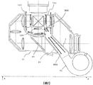
図2は、映像表示素子の送風経路を示す図である。
ライトバルブ13に光源1からの光が照射されると、映像表示素子17及び偏光板等の偏光吸収素子あるいは偏光反射素子などが加熱される。そのままでは高温になり、画像表示に悪影響を与えてしまうため、シロッコファンや軸流ファン、遠心ファンといった冷却ファン20を配置し、外気を導入し、冷却風200を各色のライトバルブ13に供給することにより温度上昇を抑えている。
特に、ライトバルブ13Gは、13R、13Bに比べ光源1から入射する光密度が大きいため、積極的に冷却風を送風する必要があり、13Bもエネルギー密度の高い短波長の光が入射されるため高温となりやすく、13Rよりも積極的に冷却する必要がある。
そこで、ライトバルブ13に冷却風200を送風するため、冷却ファン20を図2のように配置する。そして、冷却風200は、色分離光学系の光通過領域内に形成された経路を通って、液晶表示素子17に供給される。ここでは、ダイクロイックミラー7とダイクロイックミラー11の間に当該経路が形成されており、冷却風200はライトバルブ13Gとライトバルブ13Bの側面あるいは側斜面方向へと供給される。ライトバルブ13Rは13Gを通過した風で冷却される。
又、冷却風200を発散させる事無く供給するため、透過型のガラス基板22をダイクロイックミラー7とダイクロイックミラー11の間に配置し、送風ダクトの一部とすれば、より高効率の冷却を実現できる。ガラス基板22の透過率は95%以上であるのが望ましく、ガラス基板22には反射防止膜などがコーティングされていても良い。
又、風速を低下させないようにするため、冷却ファン20の送風口からライトバルブ13G、13Bまで略直線的に風を送風するようにしている。即ち、冷却ファン20の送風開口領域は、冷却風200が色分離光学系の光軸を通るようになっている。
更に、ライトバルブ13G、13Bに適当な風量を分配するため、冷却風200が色分離光学系の光路領域を通過した後の位置に、整流板300を配置しても良い。整流板300は、エンジンケース21の一部として配置しても良いし、独立した部品として配置しても良い。
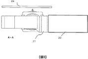
尚、送風経路の下部は、ダイクロイックミラーやコンデンサレンズといった光学部品を固定・保持するためのエンジンケース21にて形成している。一方、送風経路の上部は、図3のように蓋ケース24を用いて形成している。24としては、金属、樹脂、ゴム、シート材、パッキン、接着剤等を使用すると良い。
図4は、映像表示素子の送風経路を示す図である。図2とは異なる態様で示している。
ここでは、コンデンサレンズ23Gを用いて送風経路を形成している。図2の実施例では、集光させるのを6と12Bの2枚で行っていたのを、図4では6と12Bと23Gの3枚で行うことになる。これにより、パワー配分が分散され、部品毎のレンズ位置バラツキによるラスタずれの感度を下げることができる。
尚、コンデンサレンズ23Gに限定されるものではなく、その他の光学部品、あるいは金属や樹脂製の構造部品を用いて送風経路を形成しても良い。
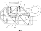
図5は、映像表示素子の送風経路を示す図である。図2、4とは異なる態様で示している。
ここでは、ダイクロイックミラー7とダイクロイックミラー8の間からライトバルブ13G、13Bに向かって冷却風を送風している。尚、図5に示すように、コンデンサレンズ23Bや、ガラス基板25等を用いて送風経路を最適化しても良い。ガラス基板25にUVカットガラスを使用した場合は、パネルへの紫外線を減少させる事も可能である。
又、光学系の設計においては、図1のライトバルブ13Rと13Bの配置が逆になる場合も考えられる。その際は、例えばダイクロイックミラー11とダイクロイックミラー10の間から冷却風を供給したり、あるいはダイクロイックミラー9とダイクロイックミラー10の間から冷却風を供給する事によって、ライトバルブ13G、13Bに冷却風を先行供給できるため、同様の効果が期待できる。
上記実施例によれば、色分離光学系の何れかの光通過領域を通して冷却ファン20から冷却風200をライトバルブ13に送風する構造としているため、色分離光学系やライトバルブと同等の高さに冷却ファン20を配置できる。従って、ライトバルブ13の冷却性能を向上させながら、装置全体の厚みを抑えられ、可搬性・携帯性に優れた装置を提供できる。又、高温となるG及びBのライトバルブに冷却風を先行供給できるため、パネルの冷却性能がより向上する。更に、既存の光学部品を用いて送風経路を形成できるため、コストを低減することができる。
尚、上記実施例のうち、ガラス基板22、コンデンサレンズ23G、ガラス基板25は、より高効率な装置を実現するために追加した部品ではあるが、結果として、冷却ファンの個数低減やセットの厚み低減につながるため、全体として、装置小型化及びコスト低減を図ることができる。
1…光源、2…反射鏡、3…第1のレンズアレイ、4…第2のレンズアレイ、5…偏光変換素子、6…集光レンズ、7…ダイクロイックミラー、8,9,10…反射ミラー、11…ダイクロイックミラー、12…コンデンサレンズ、13…ライトバルブ、14…第1のリレーレンズ、15…第2のリレーレンズ、17…映像表示素子、18…色合成プリズム、19…投射レンズ、20…冷却ファン、21…エンジンケース、22…ガラス基板、23…コンデンサレンズ、24…蓋ケース、25…ガラス基板、30…アフォーカルレンズ、100…光軸、200…冷却風、300…整流板。
Claims (5)
- 光源から出射される光を複数の光束に分割するレンズアレイと、
前記レンズアレイからの光を集光する集光レンズと、
前記集光レンズからの光の色を分離する色分離光学系と、
前記色分離光学系によって分離された光から光学像を形成する映像表示素子と、
前記光学像を投射する投射レンズと、
前記映像表示素子を冷却する冷却ファンと、を備え、
前記冷却ファンが送り出す冷却風は、前記色分離光学系の光通過領域内に形成された経路を通って、前記映像表示素子に供給される、投射型映像表示装置。 - 前記経路の一部は、前記色分離光学系に用いられる光学部品により形成される、請求項1記載の投射型映像表示装置。
- G色に対応する第1の液晶表示素子、B色に対応する第2の液晶表示素子、及び、R色に対応する第3の液晶表示素子を更に備え、
前記冷却風は、前記第3の液晶表示素子よりも先に、前記第1及び第2の液晶表示素子に供給される、請求項1又は2記載の投射型映像表示装置。 - 前記冷却ファンの送風開口領域は、前記冷却風が前記色分離光学系の光軸を通る、請求項1乃至3何れか一に記載の投射型映像表示装置。
- 前記色分離光学系と前記映像表示素子の間に、整流板が配置される、請求項1乃至4何れか一に記載の投射型映像表示装置。
Priority Applications (1)
| Application Number | Priority Date | Filing Date | Title |
|---|---|---|---|
| PCT/JP2011/003459 WO2012172615A1 (ja) | 2011-06-17 | 2011-06-17 | 投射型映像表示装置 |
Applications Claiming Priority (1)
| Application Number | Priority Date | Filing Date | Title |
|---|---|---|---|
| PCT/JP2011/003459 WO2012172615A1 (ja) | 2011-06-17 | 2011-06-17 | 投射型映像表示装置 |
Publications (1)
| Publication Number | Publication Date |
|---|---|
| WO2012172615A1 true WO2012172615A1 (ja) | 2012-12-20 |
Family
ID=47356643
Family Applications (1)
| Application Number | Title | Priority Date | Filing Date |
|---|---|---|---|
| PCT/JP2011/003459 Ceased WO2012172615A1 (ja) | 2011-06-17 | 2011-06-17 | 投射型映像表示装置 |
Country Status (1)
| Country | Link |
|---|---|
| WO (1) | WO2012172615A1 (ja) |
Citations (4)
| Publication number | Priority date | Publication date | Assignee | Title |
|---|---|---|---|---|
| JP2002244215A (ja) * | 2001-02-21 | 2002-08-30 | Sharp Corp | 光源の冷却構造および投影型画像表示装置 |
| JP2005234287A (ja) * | 2004-02-20 | 2005-09-02 | Canon Inc | 液晶プロジェクタ装置 |
| JP2005234523A (ja) * | 2004-01-23 | 2005-09-02 | Hitachi Ltd | 光源装置及びこれを用いたプロジェクタ |
| JP2010054766A (ja) * | 2008-08-28 | 2010-03-11 | Panasonic Corp | 投射型表示装置 |
-
2011
- 2011-06-17 WO PCT/JP2011/003459 patent/WO2012172615A1/ja not_active Ceased
Patent Citations (4)
| Publication number | Priority date | Publication date | Assignee | Title |
|---|---|---|---|---|
| JP2002244215A (ja) * | 2001-02-21 | 2002-08-30 | Sharp Corp | 光源の冷却構造および投影型画像表示装置 |
| JP2005234523A (ja) * | 2004-01-23 | 2005-09-02 | Hitachi Ltd | 光源装置及びこれを用いたプロジェクタ |
| JP2005234287A (ja) * | 2004-02-20 | 2005-09-02 | Canon Inc | 液晶プロジェクタ装置 |
| JP2010054766A (ja) * | 2008-08-28 | 2010-03-11 | Panasonic Corp | 投射型表示装置 |
Similar Documents
| Publication | Publication Date | Title |
|---|---|---|
| JP2011149380A (ja) | 多翼送風機 | |
| JP5241162B2 (ja) | 画像投射装置 | |
| JP4944452B2 (ja) | 画像投射装置 | |
| JP2011033674A (ja) | プロジェクター | |
| CN103959163B (zh) | 投影型影像显示装置 | |
| JP2004061569A (ja) | 投射型液晶表示装置 | |
| US8491132B2 (en) | Projector | |
| JP2005173357A (ja) | 色分離合成装置及びそれを有する映像投影装置 | |
| JP2006084990A (ja) | 投射装置 | |
| JP4630563B2 (ja) | 投射表示装置、および、画像投射システム | |
| WO2012172615A1 (ja) | 投射型映像表示装置 | |
| JP2009042329A (ja) | 画像投射装置 | |
| JP2011075763A (ja) | 投写型映像表示装置 | |
| JP4166217B2 (ja) | 照明装置及び投写型映像表示装置 | |
| JP2005121900A (ja) | 投射型表示装置、および、投射型表示装置用の光学系 | |
| JP5031212B2 (ja) | 投射型画像表示装置 | |
| JP5125967B2 (ja) | 画像表示装置および偏光変換素子 | |
| JP2004093655A (ja) | 投射型画像表示装置 | |
| JP2016045338A (ja) | 液晶プロジェクタ | |
| JPWO2013069039A1 (ja) | 投射型映像表示装置 | |
| JP2006091036A (ja) | 投射表示装置 | |
| JP4859167B2 (ja) | 光源装置及び該光源装置を有する投射型表示装置 | |
| JP5193516B2 (ja) | 投射型表示装置 | |
| JP2012008181A (ja) | プロジェクター | |
| JP2015001595A (ja) | 光源冷却ユニットおよび光源冷却装置並びに投射型表示装置 |
Legal Events
| Date | Code | Title | Description |
|---|---|---|---|
| 121 | Ep: the epo has been informed by wipo that ep was designated in this application |
Ref document number: 11867641 Country of ref document: EP Kind code of ref document: A1 |
|
| NENP | Non-entry into the national phase |
Ref country code: DE |
|
| 122 | Ep: pct application non-entry in european phase |
Ref document number: 11867641 Country of ref document: EP Kind code of ref document: A1 |
|
| NENP | Non-entry into the national phase |
Ref country code: JP |