WO2012169577A1 - Cartouche purificatrice d'eau et purificateur d'eau - Google Patents
Cartouche purificatrice d'eau et purificateur d'eau Download PDFInfo
- Publication number
- WO2012169577A1 WO2012169577A1 PCT/JP2012/064657 JP2012064657W WO2012169577A1 WO 2012169577 A1 WO2012169577 A1 WO 2012169577A1 JP 2012064657 W JP2012064657 W JP 2012064657W WO 2012169577 A1 WO2012169577 A1 WO 2012169577A1
- Authority
- WO
- WIPO (PCT)
- Prior art keywords
- water
- opening
- water purification
- purification cartridge
- container
- Prior art date
Links
- XLYOFNOQVPJJNP-UHFFFAOYSA-N water Substances O XLYOFNOQVPJJNP-UHFFFAOYSA-N 0.000 title claims abstract description 230
- 239000012528 membrane Substances 0.000 claims abstract description 44
- 239000012510 hollow fiber Substances 0.000 claims abstract description 42
- 239000008213 purified water Substances 0.000 claims abstract description 39
- 239000003463 adsorbent Substances 0.000 claims abstract description 31
- 229910001385 heavy metal Inorganic materials 0.000 claims abstract description 26
- 238000001914 filtration Methods 0.000 claims abstract description 11
- 238000000746 purification Methods 0.000 claims description 85
- 238000003860 storage Methods 0.000 claims description 37
- 239000011347 resin Substances 0.000 claims description 21
- 229920005989 resin Polymers 0.000 claims description 21
- NWUYHJFMYQTDRP-UHFFFAOYSA-N 1,2-bis(ethenyl)benzene;1-ethenyl-2-ethylbenzene;styrene Chemical compound C=CC1=CC=CC=C1.CCC1=CC=CC=C1C=C.C=CC1=CC=CC=C1C=C NWUYHJFMYQTDRP-UHFFFAOYSA-N 0.000 claims description 14
- 239000003729 cation exchange resin Substances 0.000 claims description 11
- 239000013522 chelant Substances 0.000 claims description 10
- 239000008239 natural water Substances 0.000 claims description 8
- 238000011085 pressure filtration Methods 0.000 claims description 6
- 230000007423 decrease Effects 0.000 claims description 4
- 239000007788 liquid Substances 0.000 claims 1
- 239000000463 material Substances 0.000 abstract description 4
- 238000010276 construction Methods 0.000 abstract 1
- OKTJSMMVPCPJKN-UHFFFAOYSA-N Carbon Chemical compound [C] OKTJSMMVPCPJKN-UHFFFAOYSA-N 0.000 description 26
- 239000003456 ion exchange resin Substances 0.000 description 11
- 229920003303 ion-exchange polymer Polymers 0.000 description 11
- 239000008399 tap water Substances 0.000 description 9
- 235000020679 tap water Nutrition 0.000 description 9
- 230000002378 acidificating effect Effects 0.000 description 7
- -1 residual chlorine Chemical class 0.000 description 6
- 238000005342 ion exchange Methods 0.000 description 5
- 238000004382 potting Methods 0.000 description 5
- 238000001179 sorption measurement Methods 0.000 description 5
- 229940023913 cation exchange resins Drugs 0.000 description 4
- 239000000499 gel Substances 0.000 description 4
- ZAMOUSCENKQFHK-UHFFFAOYSA-N Chlorine atom Chemical compound [Cl] ZAMOUSCENKQFHK-UHFFFAOYSA-N 0.000 description 3
- VYPSYNLAJGMNEJ-UHFFFAOYSA-N Silicium dioxide Chemical compound O=[Si]=O VYPSYNLAJGMNEJ-UHFFFAOYSA-N 0.000 description 3
- 229910021536 Zeolite Inorganic materials 0.000 description 3
- 239000003957 anion exchange resin Substances 0.000 description 3
- 239000000460 chlorine Substances 0.000 description 3
- 229910052801 chlorine Inorganic materials 0.000 description 3
- HNPSIPDUKPIQMN-UHFFFAOYSA-N dioxosilane;oxo(oxoalumanyloxy)alumane Chemical compound O=[Si]=O.O=[Al]O[Al]=O HNPSIPDUKPIQMN-UHFFFAOYSA-N 0.000 description 3
- 238000000034 method Methods 0.000 description 3
- 238000005192 partition Methods 0.000 description 3
- 239000010457 zeolite Substances 0.000 description 3
- CERQOIWHTDAKMF-UHFFFAOYSA-N Methacrylic acid Chemical group CC(=C)C(O)=O CERQOIWHTDAKMF-UHFFFAOYSA-N 0.000 description 2
- 239000004698 Polyethylene Substances 0.000 description 2
- 239000004743 Polypropylene Substances 0.000 description 2
- PPBRXRYQALVLMV-UHFFFAOYSA-N Styrene Chemical compound C=CC1=CC=CC=C1 PPBRXRYQALVLMV-UHFFFAOYSA-N 0.000 description 2
- 239000003795 chemical substances by application Substances 0.000 description 2
- 230000000382 dechlorinating effect Effects 0.000 description 2
- 125000000524 functional group Chemical group 0.000 description 2
- NBZBKCUXIYYUSX-UHFFFAOYSA-N iminodiacetic acid Chemical compound OC(=O)CNCC(O)=O NBZBKCUXIYYUSX-UHFFFAOYSA-N 0.000 description 2
- 238000003780 insertion Methods 0.000 description 2
- 230000037431 insertion Effects 0.000 description 2
- 150000002500 ions Chemical class 0.000 description 2
- 229910021645 metal ion Inorganic materials 0.000 description 2
- 239000000203 mixture Substances 0.000 description 2
- 239000002245 particle Substances 0.000 description 2
- 229920000573 polyethylene Polymers 0.000 description 2
- 229920000098 polyolefin Polymers 0.000 description 2
- 229920001155 polypropylene Polymers 0.000 description 2
- 239000000843 powder Substances 0.000 description 2
- 239000000057 synthetic resin Substances 0.000 description 2
- 229920003002 synthetic resin Polymers 0.000 description 2
- MYRTYDVEIRVNKP-UHFFFAOYSA-N 1,2-Divinylbenzene Chemical compound C=CC1=CC=CC=C1C=C MYRTYDVEIRVNKP-UHFFFAOYSA-N 0.000 description 1
- 229920000219 Ethylene vinyl alcohol Polymers 0.000 description 1
- 229910019142 PO4 Inorganic materials 0.000 description 1
- 229920002845 Poly(methacrylic acid) Polymers 0.000 description 1
- 239000004952 Polyamide Substances 0.000 description 1
- 239000004721 Polyphenylene oxide Substances 0.000 description 1
- 239000004372 Polyvinyl alcohol Substances 0.000 description 1
- 229920000297 Rayon Polymers 0.000 description 1
- BQCADISMDOOEFD-UHFFFAOYSA-N Silver Chemical compound [Ag] BQCADISMDOOEFD-UHFFFAOYSA-N 0.000 description 1
- 239000004809 Teflon Substances 0.000 description 1
- 229920006362 Teflon® Polymers 0.000 description 1
- 238000010521 absorption reaction Methods 0.000 description 1
- 230000000274 adsorptive effect Effects 0.000 description 1
- PNEYBMLMFCGWSK-UHFFFAOYSA-N aluminium oxide Inorganic materials [O-2].[O-2].[O-2].[Al+3].[Al+3] PNEYBMLMFCGWSK-UHFFFAOYSA-N 0.000 description 1
- 239000004760 aramid Substances 0.000 description 1
- 229920003235 aromatic polyamide Polymers 0.000 description 1
- 230000001580 bacterial effect Effects 0.000 description 1
- GBAOBIBJACZTNA-UHFFFAOYSA-L calcium sulfite Chemical compound [Ca+2].[O-]S([O-])=O GBAOBIBJACZTNA-UHFFFAOYSA-L 0.000 description 1
- 235000010261 calcium sulphite Nutrition 0.000 description 1
- 239000001913 cellulose Substances 0.000 description 1
- 229920002678 cellulose Polymers 0.000 description 1
- 229920001429 chelating resin Polymers 0.000 description 1
- 239000004927 clay Substances 0.000 description 1
- 238000007796 conventional method Methods 0.000 description 1
- 238000004132 cross linking Methods 0.000 description 1
- 238000003795 desorption Methods 0.000 description 1
- 230000000694 effects Effects 0.000 description 1
- 239000012535 impurity Substances 0.000 description 1
- 238000012966 insertion method Methods 0.000 description 1
- 239000011159 matrix material Substances 0.000 description 1
- 125000002496 methyl group Chemical group [H]C([H])([H])* 0.000 description 1
- 238000002156 mixing Methods 0.000 description 1
- 239000002808 molecular sieve Substances 0.000 description 1
- 229930014626 natural product Natural products 0.000 description 1
- 229910052757 nitrogen Inorganic materials 0.000 description 1
- 150000002894 organic compounds Chemical class 0.000 description 1
- 125000000962 organic group Chemical group 0.000 description 1
- 229910052760 oxygen Inorganic materials 0.000 description 1
- 238000012856 packing Methods 0.000 description 1
- 239000013618 particulate matter Substances 0.000 description 1
- 230000035699 permeability Effects 0.000 description 1
- NBIIXXVUZAFLBC-UHFFFAOYSA-K phosphate Chemical compound [O-]P([O-])([O-])=O NBIIXXVUZAFLBC-UHFFFAOYSA-K 0.000 description 1
- 239000010452 phosphate Substances 0.000 description 1
- 229920003229 poly(methyl methacrylate) Polymers 0.000 description 1
- 229920002492 poly(sulfone) Polymers 0.000 description 1
- 229920002239 polyacrylonitrile Polymers 0.000 description 1
- 229920002647 polyamide Polymers 0.000 description 1
- 229920000768 polyamine Polymers 0.000 description 1
- 239000004417 polycarbonate Substances 0.000 description 1
- 229920000515 polycarbonate Polymers 0.000 description 1
- 229920000728 polyester Polymers 0.000 description 1
- 229920000570 polyether Polymers 0.000 description 1
- 229920000642 polymer Polymers 0.000 description 1
- 239000004926 polymethyl methacrylate Substances 0.000 description 1
- 229920001343 polytetrafluoroethylene Polymers 0.000 description 1
- 239000004810 polytetrafluoroethylene Substances 0.000 description 1
- 229920002451 polyvinyl alcohol Polymers 0.000 description 1
- 239000005373 porous glass Substances 0.000 description 1
- 239000011148 porous material Substances 0.000 description 1
- 238000012545 processing Methods 0.000 description 1
- 239000000741 silica gel Substances 0.000 description 1
- 229910002027 silica gel Inorganic materials 0.000 description 1
- 239000000377 silicon dioxide Substances 0.000 description 1
- 229910052709 silver Inorganic materials 0.000 description 1
- 239000004332 silver Substances 0.000 description 1
- 239000011734 sodium Substances 0.000 description 1
- URGAHOPLAPQHLN-UHFFFAOYSA-N sodium aluminosilicate Chemical compound [Na+].[Al+3].[O-][Si]([O-])=O.[O-][Si]([O-])=O URGAHOPLAPQHLN-UHFFFAOYSA-N 0.000 description 1
- 235000010378 sodium ascorbate Nutrition 0.000 description 1
- 229960005055 sodium ascorbate Drugs 0.000 description 1
- PPASLZSBLFJQEF-RKJRWTFHSA-M sodium ascorbate Substances [Na+].OC[C@@H](O)[C@H]1OC(=O)C(O)=C1[O-] PPASLZSBLFJQEF-RKJRWTFHSA-M 0.000 description 1
- PPASLZSBLFJQEF-RXSVEWSESA-M sodium-L-ascorbate Chemical compound [Na+].OC[C@H](O)[C@H]1OC(=O)C(O)=C1[O-] PPASLZSBLFJQEF-RXSVEWSESA-M 0.000 description 1
- 125000000542 sulfonic acid group Chemical group 0.000 description 1
- 229910052717 sulfur Inorganic materials 0.000 description 1
- 239000012608 weak cation exchange resin Substances 0.000 description 1
- 238000003466 welding Methods 0.000 description 1
Images


Classifications
-
- B—PERFORMING OPERATIONS; TRANSPORTING
- B01—PHYSICAL OR CHEMICAL PROCESSES OR APPARATUS IN GENERAL
- B01D—SEPARATION
- B01D63/00—Apparatus in general for separation processes using semi-permeable membranes
- B01D63/02—Hollow fibre modules
- B01D63/024—Hollow fibre modules with a single potted end
- B01D63/0241—Hollow fibre modules with a single potted end being U-shaped
-
- C—CHEMISTRY; METALLURGY
- C02—TREATMENT OF WATER, WASTE WATER, SEWAGE, OR SLUDGE
- C02F—TREATMENT OF WATER, WASTE WATER, SEWAGE, OR SLUDGE
- C02F1/00—Treatment of water, waste water, or sewage
- C02F1/001—Processes for the treatment of water whereby the filtration technique is of importance
- C02F1/003—Processes for the treatment of water whereby the filtration technique is of importance using household-type filters for producing potable water, e.g. pitchers, bottles, faucet mounted devices
-
- B—PERFORMING OPERATIONS; TRANSPORTING
- B01—PHYSICAL OR CHEMICAL PROCESSES OR APPARATUS IN GENERAL
- B01D—SEPARATION
- B01D63/00—Apparatus in general for separation processes using semi-permeable membranes
- B01D63/02—Hollow fibre modules
- B01D63/024—Hollow fibre modules with a single potted end
-
- B—PERFORMING OPERATIONS; TRANSPORTING
- B01—PHYSICAL OR CHEMICAL PROCESSES OR APPARATUS IN GENERAL
- B01D—SEPARATION
- B01D2311/00—Details relating to membrane separation process operations and control
- B01D2311/26—Further operations combined with membrane separation processes
- B01D2311/2626—Absorption or adsorption
-
- B—PERFORMING OPERATIONS; TRANSPORTING
- B01—PHYSICAL OR CHEMICAL PROCESSES OR APPARATUS IN GENERAL
- B01D—SEPARATION
- B01D2313/00—Details relating to membrane modules or apparatus
- B01D2313/40—Adsorbents within the flow path
-
- B—PERFORMING OPERATIONS; TRANSPORTING
- B01—PHYSICAL OR CHEMICAL PROCESSES OR APPARATUS IN GENERAL
- B01D—SEPARATION
- B01D2313/00—Details relating to membrane modules or apparatus
- B01D2313/44—Cartridge types
-
- C—CHEMISTRY; METALLURGY
- C02—TREATMENT OF WATER, WASTE WATER, SEWAGE, OR SLUDGE
- C02F—TREATMENT OF WATER, WASTE WATER, SEWAGE, OR SLUDGE
- C02F1/00—Treatment of water, waste water, or sewage
- C02F1/28—Treatment of water, waste water, or sewage by sorption
- C02F1/281—Treatment of water, waste water, or sewage by sorption using inorganic sorbents
-
- C—CHEMISTRY; METALLURGY
- C02—TREATMENT OF WATER, WASTE WATER, SEWAGE, OR SLUDGE
- C02F—TREATMENT OF WATER, WASTE WATER, SEWAGE, OR SLUDGE
- C02F1/00—Treatment of water, waste water, or sewage
- C02F1/28—Treatment of water, waste water, or sewage by sorption
- C02F1/283—Treatment of water, waste water, or sewage by sorption using coal, charred products, or inorganic mixtures containing them
-
- C—CHEMISTRY; METALLURGY
- C02—TREATMENT OF WATER, WASTE WATER, SEWAGE, OR SLUDGE
- C02F—TREATMENT OF WATER, WASTE WATER, SEWAGE, OR SLUDGE
- C02F1/00—Treatment of water, waste water, or sewage
- C02F1/28—Treatment of water, waste water, or sewage by sorption
- C02F1/285—Treatment of water, waste water, or sewage by sorption using synthetic organic sorbents
-
- C—CHEMISTRY; METALLURGY
- C02—TREATMENT OF WATER, WASTE WATER, SEWAGE, OR SLUDGE
- C02F—TREATMENT OF WATER, WASTE WATER, SEWAGE, OR SLUDGE
- C02F1/00—Treatment of water, waste water, or sewage
- C02F1/42—Treatment of water, waste water, or sewage by ion-exchange
-
- C—CHEMISTRY; METALLURGY
- C02—TREATMENT OF WATER, WASTE WATER, SEWAGE, OR SLUDGE
- C02F—TREATMENT OF WATER, WASTE WATER, SEWAGE, OR SLUDGE
- C02F1/00—Treatment of water, waste water, or sewage
- C02F1/44—Treatment of water, waste water, or sewage by dialysis, osmosis or reverse osmosis
- C02F1/444—Treatment of water, waste water, or sewage by dialysis, osmosis or reverse osmosis by ultrafiltration or microfiltration
-
- C—CHEMISTRY; METALLURGY
- C02—TREATMENT OF WATER, WASTE WATER, SEWAGE, OR SLUDGE
- C02F—TREATMENT OF WATER, WASTE WATER, SEWAGE, OR SLUDGE
- C02F1/00—Treatment of water, waste water, or sewage
- C02F1/42—Treatment of water, waste water, or sewage by ion-exchange
- C02F2001/425—Treatment of water, waste water, or sewage by ion-exchange using cation exchangers
-
- C—CHEMISTRY; METALLURGY
- C02—TREATMENT OF WATER, WASTE WATER, SEWAGE, OR SLUDGE
- C02F—TREATMENT OF WATER, WASTE WATER, SEWAGE, OR SLUDGE
- C02F2101/00—Nature of the contaminant
- C02F2101/10—Inorganic compounds
- C02F2101/12—Halogens or halogen-containing compounds
-
- C—CHEMISTRY; METALLURGY
- C02—TREATMENT OF WATER, WASTE WATER, SEWAGE, OR SLUDGE
- C02F—TREATMENT OF WATER, WASTE WATER, SEWAGE, OR SLUDGE
- C02F2101/00—Nature of the contaminant
- C02F2101/10—Inorganic compounds
- C02F2101/20—Heavy metals or heavy metal compounds
-
- C—CHEMISTRY; METALLURGY
- C02—TREATMENT OF WATER, WASTE WATER, SEWAGE, OR SLUDGE
- C02F—TREATMENT OF WATER, WASTE WATER, SEWAGE, OR SLUDGE
- C02F2101/00—Nature of the contaminant
- C02F2101/30—Organic compounds
- C02F2101/36—Organic compounds containing halogen
-
- C—CHEMISTRY; METALLURGY
- C02—TREATMENT OF WATER, WASTE WATER, SEWAGE, OR SLUDGE
- C02F—TREATMENT OF WATER, WASTE WATER, SEWAGE, OR SLUDGE
- C02F2201/00—Apparatus for treatment of water, waste water or sewage
- C02F2201/002—Construction details of the apparatus
- C02F2201/004—Seals, connections
-
- C—CHEMISTRY; METALLURGY
- C02—TREATMENT OF WATER, WASTE WATER, SEWAGE, OR SLUDGE
- C02F—TREATMENT OF WATER, WASTE WATER, SEWAGE, OR SLUDGE
- C02F2201/00—Apparatus for treatment of water, waste water or sewage
- C02F2201/002—Construction details of the apparatus
- C02F2201/006—Cartridges
-
- C—CHEMISTRY; METALLURGY
- C02—TREATMENT OF WATER, WASTE WATER, SEWAGE, OR SLUDGE
- C02F—TREATMENT OF WATER, WASTE WATER, SEWAGE, OR SLUDGE
- C02F2307/00—Location of water treatment or water treatment device
- C02F2307/04—Location of water treatment or water treatment device as part of a pitcher or jug
-
- C—CHEMISTRY; METALLURGY
- C02—TREATMENT OF WATER, WASTE WATER, SEWAGE, OR SLUDGE
- C02F—TREATMENT OF WATER, WASTE WATER, SEWAGE, OR SLUDGE
- C02F2307/00—Location of water treatment or water treatment device
- C02F2307/06—Mounted on or being part of a faucet, shower handle or showerhead
Definitions
- the present invention relates to a water purification cartridge.
- the present invention also relates to a water purifier equipped with the water purification cartridge.
- a pot-type water purifier As a water purifier equipped with a water purification cartridge, for example, a pot-type water purifier is known.
- This pot-type water purifier has a structure in which a water purification cartridge is interposed between a raw water storage part located on the upper side and a purified water storage part located on the lower side. The raw water stored in the raw water storage part flows into the purified water storage part through the water purification cartridge by its own weight, and is purified in the water purification cartridge.
- a water purification cartridge with which a pot type water purifier is mounted for example, one described in Patent Document 1 can be cited. In such a water purification cartridge, an ion exchange resin is used as a filter medium.
- an adsorbent such as a chelate resin or an ion exchange resin is used to remove heavy metals such as lead contained in tap water.
- a hollow fiber membrane is also used, and the hollow fiber membrane is generally disposed on the downstream side of the adsorbent.
- the state of heavy metals contained in tap water differs in countries and regions, and conventional water purification cartridges using adsorbents that change the pH of water such as ion exchange resins cannot sufficiently remove heavy metals.
- adsorbents that change the pH of water such as ion exchange resins cannot sufficiently remove heavy metals.
- the pH of tap water is around 8
- a large amount of lead contained in tap water exists in a particle state rather than an ionic state.
- the particulate lead entering the container from the raw water inlet is difficult to be adsorbed by the adsorbent, and therefore flows downstream of the adsorption layer.
- the pH of water changes with an ion exchange resin etc. in the downstream of an adsorption layer, and it tends to be acidic.
- lead is present in an ionic state more than the particulate matter. Therefore, lead may be in an ionic state on the downstream side of the adsorption layer and may pass through the hollow fiber membrane.
- an object of the present invention is to provide a water purification cartridge capable of effectively removing heavy metals contained in raw water even when the water quality is different.
- the present invention has a first opening and a second opening, any one of the first opening and the second opening can be used as a raw water inlet,
- the water purification cartridge according to the present invention can select the direction to be attached to the water source according to the water quality situation, it can efficiently remove heavy metals contained in the raw water regardless of the water quality in the country or region. .
- the water purification cartridge of the present invention has a first opening and a second opening, and any one of the first opening and the second opening can be used as a raw water inlet. And a container having a structure in which the other can be used as a purified water discharge port. Moreover, the water purification cartridge of this invention equips the said container with the filter medium containing the adsorbent which can adsorb
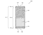
- FIG. 1 is a schematic cross-sectional view for explaining a structural example of a self-weight filtration type water purification cartridge according to an embodiment of the present invention.
- a water purification cartridge 1001 includes a container 101 that houses a filter medium 104 and a hollow fiber membrane 105 therein.
- the filter medium 104 includes an adsorbent that can adsorb heavy metals.
- the container 101 is disposed at a cylindrical case body 101b that accommodates the filter medium 104 and the hollow fiber membrane 105, a first lid 101a disposed at one end of the case 101b, and the other end of the case body 101b.
- the second lid 101c is mainly configured.
- a first opening 102 is provided at the center of the first lid 101a, and a second opening 103 is also provided at the center of the second lid 101c.
- the filter medium 104 and the hollow fiber membrane 105 are disposed in the container 101 in order from the first opening 102 toward the second opening.
- the hollow fiber membrane 105 is fixed in the container using a potting resin 106 at the end of the case body 102b on the second lid 103 side.
- the end portion of the hollow fiber membrane 105 is open on the surface side opposite to the surface on which the hollow fiber membrane of the potting resin 106 is disposed. Water can enter and exit from the opening of the hollow fiber membrane.
- the filter medium 104 is accommodated in the container by a partition wall 107 through which water can pass.
- connection between the first lid 101a and the case body 101b, and the second lid 101c and the case body 101b for example, bonding or welding can be used.
- any one of the first opening 102 and the second opening 103 can function as both a raw water inlet for taking raw water into the container and a purified water outlet for sending purified water to the outside of the container.
- the first opening 102 functions as a raw water inlet
- the second opening 103 functions as a purified water discharge port
- the first opening 102 Functions as a water purification outlet.
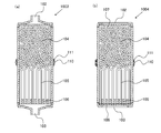
- FIG. 2 shows a configuration example of a water purifier including the water purification cartridge 1001 shown in FIG.
- the water purification cartridge 1001 is disposed in the housing portion 202b with the first opening 102 facing upward.
- the vertical direction of the water purification cartridge in this specification represents the direction in the state arrange
- the water purifier 200 is supplied with raw water such as tap water and stored therein, a water purification cartridge 1001 attached to the bottom of the raw water storage unit 204, and below the raw water storage unit 204 and the water purification cartridge 1001. It forms a main body with the clean water storage part 203 located.
- the raw water stored in the raw water storage unit 204 is purified when passing through the water purification cartridge 1001 by its own weight, and flows down to the purified water storage unit 203.
- the water purifier 200 includes a bottomed cylindrical outer container 201 having an open upper end, and a bottomed cylindrical inner container 202 having an open upper end that is inserted from the upper end opening of the outer container 201 and disposed in the outer container 201. It has.
- the inner container 202 is arranged at a depth of about half or less than the outer container 201, and the contents of the inner container 202 are fitted to the upper half of the outer container 201 without any gaps except for the predetermined gap 205.
- the raw water storage unit 204 is formed in the vessel 202.
- a purified water storage unit 203 is provided between the bottom wall 202 a of the inner container 202 and the bottom wall 201 a of the outer container 201.
- the gap 205 is formed so as to extend upward from the purified water storage unit 203 and functions as a pouring path when the purified water is poured.
- An upper lid portion 206 is fitted into the upper end opening of the inner container 202.
- the upper lid 206 may be provided with an openable / closable flap that opens a water supply port at the center and closes the water supply port from above.
- An opening formed at the upper end of the gap 205 functions as a pouring spout, and a pouring lid 207 is provided at the pouring spout.
- the bottom wall 202a of the inner container is provided with a housing portion 202b for housing the water purification cartridge, and the bottom wall 202a of the inner container is formed with a gentle downward slope toward the housing portion 202b.
- the water purification cartridge housing portion 202b is recessed in the bottom wall 202a of the inner container toward the water purification storage portion.
- the water purification cartridge 1001 is fitted into the housing portion 202b from above.
- the center of the bottom of the storage unit 202b is opened, and the raw water storage unit 204 and the purified water located below the storage unit 202b and the opening of the bottom, that is, through the water purification cartridge 1001 attached to the storage unit 202b.
- the storage unit 203 communicates with the storage unit 203.
- the water purification cartridge 1001 can be attached to the storage unit 202b by using a screw-in type or a ratchet type in addition to the insertion type using rubber packing, and is not particularly limited.
- the water purification cartridge 1001 is disposed in the housing portion 202b with the first opening 102 facing upward.
- the 1st opening part 102 functions as a raw
- the 2nd opening part 103 functions as a purified water discharge port.
- the raw water in the raw water storage unit 204 enters the container from the first opening 102 by its own weight.
- the water filtered by the filter medium 104 is further filtered by the hollow fiber membrane 105 and flows out from the end opening of the hollow fiber membrane.
- the obtained purified water is discharged
- the pH of tap water when the pH of tap water is less than 8, lead contained in tap water tends to exist in an ionic state rather than a particulate state. Since lead in an ionic state is easily adsorbed by the filter medium, as shown in FIG. 2, it is better to arrange the first opening 102 upward so that the raw water flows through the filter medium before the hollow fiber membrane. Lead can be removed efficiently.
- the pH of tap water is greater than 8, the lead contained in the tap water tends to exist in a particulate state. In this case, as shown in FIG. 3, the lead can be more efficiently removed by arranging the second opening 103 upward and removing lead with a hollow fiber membrane before the filter medium.
- the 2nd opening part 103 functions as a raw
- the water purification cartridge according to the present invention can efficiently remove heavy metals contained in the raw water by selecting the arrangement direction according to the state of the raw water.
- the filter medium in the present invention includes an adsorbent capable of adsorbing heavy metals (hereinafter abbreviated as heavy metal adsorbent).
- the heavy metal adsorbent is not particularly limited as long as it can adsorb heavy metals, but for example, an ion exchange resin or a chelate resin can be used.
- An ion exchange resin is a kind of synthetic resin and has a structure that ionizes as an ion exchange group in a part of its molecular structure.
- Ion exchange resins are classified into cation exchange resins and anion exchange resins according to the nature of the ion exchange groups.
- cation exchange resins are classified into H type, Na type, K type, etc., depending on the type of ion exchange group. It is done.
- H-type cation exchange resin among the ion exchange resins.
- Examples of ion exchange groups possessed by the H-type cation exchange resin include sulfonic acid groups and (meth) acrylic acid groups.
- a cation exchange resin having a (meth) acrylic acid group is generally called a weakly acidic cation exchange resin.
- the ion exchange resin is a synthetic resin having a functional group (exchange group) for performing ion exchange on the resin matrix, and can exchange ions held in the resin with ions in the solution.
- Ion exchange resins are roughly classified into four types, namely, strongly acidic cation exchange resins, weakly acidic cation exchange resins, strongly basic anion exchange resins, and weakly basic anion exchange resins.
- the chelate resin is a resin in which a functional group that mainly forms a chelate (complex) with a metal ion is introduced, and a specific metal ion can be captured by forming a chelate.
- the chelate resin generally has a chelate-forming group containing two or more electron donating elements such as N, S, O, and P, and can be classified into iminodiacetic acid type, polyamine type, glucamine type, and the like depending on the combination structure. .
- an iminodiacetic acid type chelate resin is preferable from the viewpoint of efficiently removing heavy metals.
- the ion exchange resin and the chelate resin are classified into gel type, porous type, high porous type, MR (macro-reticular) type and the like according to their properties.
- the gel type resin has only micropores formed by a three-dimensional structure of styrene and divinylbenzene (DVB).
- High porous type resins and MR type resins have macropores in addition to micropores.
- High porous resins and MR resins generally have a high degree of crosslinking.
- the porous type is located between the gel type and the high porous type.
- the H-type cation exchange resin and chelate resin used in the present invention are preferably a high porous type or an MR type, and more preferably an MR type.
- the filter medium may include an adsorbent other than the heavy metal adsorbent.
- adsorbents include natural product-based adsorbents (natural zeolite, silver zeolite, acidic clay, etc.), or synthetic-based adsorbents (synthetic zeolite, bacterial adsorption polymer, phosphate ore, molecular sieve, silica gel, silica, etc.
- inorganic adsorbents such as alumina gel and porous glass. Examples of such an adsorbent include a powder adsorbent, a granular adsorbent obtained by granulating the powder adsorbent, or a fibrous adsorbent.
- activated carbon as the adsorbent.
- activated carbon include powdered activated carbon, granular activated carbon, fibrous activated carbon, block activated carbon, extruded activated carbon, molded activated carbon, synthetic granular activated carbon, and synthetic activated carbon.
- fibrous activated carbon examples include fibrous activated carbon.
- a dechlorinating agent excellent in removing residual chlorine can be preferably used.
- the dechlorinating agent calcium sulfite and sodium ascorbate that can maintain the effect of removing chlorine for a long time are preferable.
- the filter medium can contain, for example, 10% by volume or more of heavy metal adsorbent with respect to the entire filter medium, preferably 20% by volume or more, more preferably 30% by volume or more, and more preferably 40% by volume or more. preferable.
- an adsorbent can be used by 1 type or in combination of 2 or more types.
- the hollow fiber membrane in the present invention is not particularly limited, and examples thereof include cellulose-based, polyolefin (polyethylene, polypropylene) -based, polyvinyl alcohol-based, ethylene-vinyl alcohol copolymer, polyether-based, polymethacrylic acid.
- examples include those made of various materials such as methyl (PMMA), polysulfone, polyacrylonitrile, polytetrafluoroethylene (Teflon (registered trademark)), polycarbonate, polyester, polyamide, and aromatic polyamide. It is done.
- polyolefin-based hollow fiber membranes such as polyethylene and polypropylene are preferred.
- the hollow fiber membrane preferably has an outer diameter of 20 to 2000 ⁇ m, a pore diameter of 0.01 to 1 ⁇ m, a porosity of 20 to 90%, and a film thickness of 5 to 300 ⁇ m.
- the hollow fiber membrane is desirably a so-called hydrophilic hollow fiber membrane having a hydrophilic group on the surface.
- the shape of the side surface of the container is not particularly limited, but may be a substantially cylindrical shape, for example.
- the shape of the opening surface of the first opening and the second opening is not particularly limited, but can be, for example, a circular shape, an elliptical shape, or a polygonal shape, and may be an indefinite shape.
- the first opening and the second opening are not particularly limited, but preferably have the same shape. In particular, if the respective members constituting the first opening and the second opening have the same shape, they can be easily arranged in the accommodating portion in any direction.
- FIG. 4 is a schematic cross-sectional view showing a preferred configuration example of the present embodiment.
- the shape of the container is substantially cylindrical including the first lid 101a and the second lid 101c.
- a first opening 102 is provided on the upper surface of the substantially cylindrical container, and a partition wall 107 having water permeability for storing the filter medium 104 in the container is provided immediately below the first opening 102.
- the hollow fiber membrane 105 is accommodated in the container by a potting resin 106.
- a second opening 102 is provided on the lower surface of the substantially cylindrical container.
- a filter 108 is provided between the second opening 102 and the potting resin 106.
- FIG. 5 is a schematic cross-sectional view showing a state in which the water purification cartridge 1002 shown in FIG. 4 is disposed in the accommodating portion 202b.
- the opening surface of the first opening portion 102 is located at the same height or lower than the upper end of the housing portion. That is, the opening surface of the first opening portion 102 is equal to or lower than the height of the upper end of the housing portion.
- the opening surfaces of the first opening portion 102 and the second opening portion 103 are positioned below the height of the upper end of the housing portion.
- a configuration is preferable. By setting it as such a structure, even if it arrange
- the container shape of the water purification cartridge into a substantially cylindrical shape, the area of the first opening and the area of the second opening can be increased, the volume of the filter medium and the hollow fiber membrane can be effectively secured, and the raw water introduction efficiency and A water purification cartridge excellent in filtration efficiency can be provided.
- the water purification cartridge of this embodiment has the structure by which the fitting part with the accommodating part is provided in the center vicinity of the up-down direction of a container. By fitting a part of the fitting portion and the accommodating portion, the water purification cartridge is accommodated in a liquid-tight manner. Since the fitting portion with the accommodating portion is provided near the center of the container, the position of the opening for introducing the raw water into the container can be made constant even if it is inserted into the accommodating portion in an arbitrary direction.
- the fitting portion is provided in the circumferential direction near the center of the container. More preferably, the fitting portion is provided in the circumferential direction near the center of the side surface of the container.
- the fitting method can be an insertion method using an elastic body, a screw-in method, a ratchet method, or the like, and is not particularly limited. From the viewpoint of ease of desorption, an insertion type using an elastic body is preferable.
- positioning in the water purifier of a water purification cartridge is not restricted to the case where it inserts from the upper side of a accommodating part, It can also be set as the structure inserted and removed from lower side.
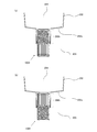
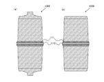
- FIG. 6 is a schematic cross-sectional view showing a preferred configuration example of the present embodiment.
- a water purification cartridge 1003 shown in FIG. 6 has a configuration in which an O-ring 110 made of an elastic body is provided at the center in the vertical direction of the container of the water purification cartridge 1001 shown in FIG. 1 (FIG. 6A).
- the O-ring 110 is fitted in the groove constituting part 111.
- the water purification cartridge 1004 has a configuration in which an O-ring 110 made of an elastic body is provided at the center in the vertical direction of the container of the water purification cartridge 1002 shown in FIG. 4 (FIG. 6B).
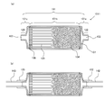
- FIG. 7 is a schematic cross-sectional view showing a state in which the water purification cartridge 1004 is arranged in the housing portion 202b of the pod type water purifier.
- FIG. 7A shows a state in which the first opening 102 is arranged toward the raw water storage unit
- FIG. 7B shows a state in which the second opening 103 is arranged toward the raw water storage unit.
- the water purifier accommodating portion 202b is formed to be inclined so that the horizontal cross-sectional area decreases from the top to the bottom. Moreover, it is preferable that any cross-sectional center in the horizontal direction of the accommodating part of a water purifier is located on the centerline along the up-down direction of a accommodating part.
- An O-ring 110 provided in the vicinity of the center of the water purification cartridge 1004 in the vertical direction is fitted in close contact with the side wall of the housing portion 202b. The water-purifying cartridge is pressed against the O-ring and the side wall of the housing portion by its own weight, and is liquid-tightly fitted.
- the opening surfaces of the first opening portion 102 and the second opening portion 103 are positioned below the height of the upper end of the housing portion even in a state of being arranged in the housing portion in an arbitrary direction.
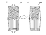
- the water purification cartridge may have a configuration in which the side wall of the container is inclined so that the horizontal cross-sectional area decreases from the vicinity of the center in the vertical direction toward both ends. Moreover, it is preferable that any cross-sectional center in the horizontal direction of a container side wall part is located on the centerline in alignment with the up-down direction of a container. By setting it as such a container, it becomes easy to insert in an accommodating part from arbitrary directions. Examples of such a container shape include a substantially barrel shape.
- FIG. 9 shows the external shape of the water purification cartridge shown in FIG.
- the water purification cartridge shown in FIG. 8 has a container whose side wall is inclined so that the cross-sectional area in the horizontal direction decreases from near the center toward both ends.
- An O-ring 110 is provided as a fitting portion near the center of the container.
- an approximately barrel-shaped container is used, and by providing the first opening and the second opening on the upper and lower surfaces of the container, the area of the opening is reduced. It is possible to provide a water purification cartridge that can be widely used, can effectively secure the volume of the filter medium and the hollow fiber membrane, and is excellent in raw water introduction efficiency and filtration efficiency.
- the opening surfaces of the first opening 102 and the second opening 103 are arranged at the upper end of the housing portion in a state of being arranged in the housing portion in an arbitrary direction. It is preferable to be located below the height.
- the fitting portion may be provided in the vicinity of both ends of the side surface of the container.
- the water purification cartridge can be arranged in the accommodating part in an arbitrary direction.
- a first O-ring 112a is fitted into a first groove constituting portion 113a provided in the vicinity of the upper end of the container side surface to constitute a first fitting portion.
- a second O-ring 112b is fitted into a second groove constituting portion 113b provided near the lower end of the container side surface to constitute a second fitting portion.
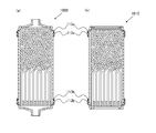
- FIG. 12 (a) is a schematic cross-sectional view for explaining an embodiment of a pressure filtration type according to this embodiment.
- FIG. 12B is a schematic cross-sectional view showing a state where the pressure filtration type water purification cartridge shown in FIG. 12A is connected to the raw water supply pipe 142 and the purified water delivery pipe 143.
- the raw water supply pipe 142 and the purified water delivery pipe 143 can be grasped as part of the configuration of the water purifier.
- 122 represents the first connecting portion
- 123 represents the second connecting portion.
- the first opening portion 102 is exposed at the first connecting portion 122
- the second opening portion 103 is exposed at the second connecting portion 123.
- the 1st connection part 122 is provided in the 1st cover part 101a
- the 2nd connection part 123 is provided in the 2nd cover part 101c.
- the first connecting portion 122 is connected to the raw water supply pipe 142 via the first connection member 132 in FIG. 12B, but can also be connected to the purified water delivery pipe 143 via the second connection member 133. It is configured. Moreover, although the 2nd connection part 123 is connected to the purified water delivery pipe 143 via the 2nd connection member 133 in FIG.12 (b), the raw
- the raw water flows into the first opening 102.
- the raw water flows from the first opening 102 to the filter medium 104 and is filtered through the filter medium 104 and the hollow fiber membrane 105.
- the obtained purified water is sent from the second opening 103 to the purified water delivery pipe 143.
- a faucet is provided at the end of the purified water delivery pipe 143.
- the second connecting portion 123 is connected to the raw water supply pipe 142 and the first connecting portion 122 is connected to the purified water delivery pipe 143
- the raw water flows into the second opening 103.
- the raw water then flows from the second opening 103 to the hollow fiber membrane 105 and is filtered through the hollow fiber membrane 105 and the filter medium 104.
- the obtained purified water is sent from the first opening 102 to the purified water delivery pipe 143.
- Such a connection state is effective when the heavy metal contained in the raw water is present in a particle state.
- the connecting portion and the connecting member are not particularly limited, and for example, a conventional method can be adopted. If each of the first connecting portion and the second connecting portion can be connected to each of the first connecting member and the second connecting member, it can be connected in any direction.
- the water purification cartridge according to the present embodiment can be installed in, for example, a sink, but is not limited to this.
- Example 1 In this example, a water purification cartridge having the structure shown in FIG. 1 was produced and evaluated.
- an H-type weak cation exchange resin (weakly acidic cation exchange resin, MR type, manufactured by Organo Corporation, trade name: Amberlite (registered trademark) IRC76) was used.
- an MF membrane membrane area: 0.16 m 2 , Mitsubishi Rayon Co., Ltd., trade name: EX270 was used.
- the prepared water purification cartridge was set in a water purifier housing having the structure shown in FIG. 2 and water was passed in accordance with NSF / ANSI 50 Lead (pH 8.5). The direction to arrange was evaluated about the case where the 1st opening was arranged towards the raw water storage part, and the case where the 2nd opening was arranged towards the raw water storage part, respectively.
- FIG. 13 shows the results of integrated flow rate and Pb concentration of filtered water.
- ⁇ is the result of evaluating the hollow fiber membrane side facing the raw water reservoir so that water flows in the order from the hollow fiber membrane to the filter medium.
- delta) is the result of having arrange
- the water purification cartridge according to the present invention can effectively remove heavy metals by selecting the direction of arrangement according to the water quality.
Abstract
La présente invention concerne une cartouche purificatrice d'eau capable d'éliminer efficacement les métaux lourds présents dans de l'eau brute, indépendamment de la qualité de l'eau. Un aspect de la présente invention concerne une cartouche purificatrice d'eau située dans un récipient, un matériau de filtration contenant un adsorbant permettant de modifier le pH de l'eau, et une membrane à fibres creuses. Le récipient comporte deux ouvertures, et est construit de façon que l'une ou l'autre des ouvertures peut être utilisée comme entrée pour introduire l'eau brute et l'autre ouverture peut être utilisée comme sortie d'eau purifiée. Le matériau de filtration et la membrane à fibres creuses sont situés dans le récipient dans cet ordre, d'une des ouvertures vers l'autre.
Priority Applications (3)
| Application Number | Priority Date | Filing Date | Title |
|---|---|---|---|
| CN201280028553.7A CN103702943A (zh) | 2011-06-10 | 2012-06-07 | 净水滤筒以及净水器 |
| EP12796824.6A EP2733120A4 (fr) | 2011-06-10 | 2012-06-07 | Cartouche purificatrice d'eau et purificateur d'eau |
| JP2012528578A JP5609978B2 (ja) | 2011-06-10 | 2012-06-07 | 浄水カートリッジおよび浄水器 |
Applications Claiming Priority (2)
| Application Number | Priority Date | Filing Date | Title |
|---|---|---|---|
| JP2011130418 | 2011-06-10 | ||
| JP2011-130418 | 2011-06-10 |
Publications (1)
| Publication Number | Publication Date |
|---|---|
| WO2012169577A1 true WO2012169577A1 (fr) | 2012-12-13 |
Family
ID=47296134
Family Applications (1)
| Application Number | Title | Priority Date | Filing Date |
|---|---|---|---|
| PCT/JP2012/064657 WO2012169577A1 (fr) | 2011-06-10 | 2012-06-07 | Cartouche purificatrice d'eau et purificateur d'eau |
Country Status (4)
| Country | Link |
|---|---|
| EP (1) | EP2733120A4 (fr) |
| JP (1) | JP5609978B2 (fr) |
| CN (1) | CN103702943A (fr) |
| WO (1) | WO2012169577A1 (fr) |
Cited By (3)
| Publication number | Priority date | Publication date | Assignee | Title |
|---|---|---|---|---|
| KR20180132718A (ko) * | 2016-04-22 | 2018-12-12 | 폴 코포레이션 | 수처리 장치 |
| JP2019514668A (ja) * | 2016-04-22 | 2019-06-06 | ポール・コーポレーションPall Corporation | 水処理装置 |
| CN117023742A (zh) * | 2023-08-16 | 2023-11-10 | 江苏久智环境科技服务有限公司 | 一种蓄水水储罐净水装置 |
Families Citing this family (3)
| Publication number | Priority date | Publication date | Assignee | Title |
|---|---|---|---|---|
| WO2017204743A1 (fr) * | 2016-05-23 | 2017-11-30 | Asxban Technologies Pte Ltd | Appareil de traitement de fluide contenant des contaminants |
| CN105948284A (zh) * | 2016-07-17 | 2016-09-21 | 珠海大卫卫浴科技有限公司 | 一种外置式净化水与反渗透过滤水龙头 |
| DE102020129849A1 (de) * | 2020-11-12 | 2022-05-12 | Bwt Holding Gmbh | Vorrichtung und Verfahren zum Schutz von Trinkwasser vor Mikroorganismen |
Citations (6)
| Publication number | Priority date | Publication date | Assignee | Title |
|---|---|---|---|---|
| JPH0183487U (fr) * | 1987-11-16 | 1989-06-02 | ||
| JP2001252654A (ja) * | 2000-03-13 | 2001-09-18 | Yoshikazu Kumihigashi | 燃焼廃ガスまたは産業廃液の浄化方法および環境汚染物質の浄化装置 |
| JP2003514647A (ja) | 1999-11-02 | 2003-04-22 | ブリタ ゲーエムベーハー | 液体用濾過装置 |
| JP2004230335A (ja) * | 2003-01-31 | 2004-08-19 | Mitsubishi Rayon Co Ltd | 浄水カートリッジ及び浄水器 |
| WO2005110926A1 (fr) * | 2004-05-18 | 2005-11-24 | Mitsubishi Rayon Co., Ltd. | Purificateur d'eau |
| JP2008214895A (ja) * | 2007-03-01 | 2008-09-18 | Kajima Corp | 地下水調査方法 |
Family Cites Families (6)
| Publication number | Priority date | Publication date | Assignee | Title |
|---|---|---|---|---|
| JPH07136649A (ja) * | 1993-11-17 | 1995-05-30 | Sanyo Electric Co Ltd | 浄水器 |
| JP3467606B2 (ja) * | 1994-06-21 | 2003-11-17 | 松下電器産業株式会社 | 浄水機能付冷水生成器 |
| JP3635934B2 (ja) * | 1998-08-17 | 2005-04-06 | 松下電工株式会社 | 浄水装置の洗浄方法 |
| CN1262482C (zh) * | 2000-12-25 | 2006-07-05 | 三菱丽阳株式会社 | 罐壶型净水器及该净水器用净水筒 |
| US20080105618A1 (en) * | 2006-10-27 | 2008-05-08 | Mesosystems Technology, Inc. | Method and apparatus for the removal of harmful contaminants from portable drinking water devices |
| CN201485338U (zh) * | 2009-07-21 | 2010-05-26 | 展银(香港)有限公司 | 可以分体组合和多级组合的自来水净化装置 |
-
2012
- 2012-06-07 WO PCT/JP2012/064657 patent/WO2012169577A1/fr active Application Filing
- 2012-06-07 CN CN201280028553.7A patent/CN103702943A/zh active Pending
- 2012-06-07 EP EP12796824.6A patent/EP2733120A4/fr not_active Withdrawn
- 2012-06-07 JP JP2012528578A patent/JP5609978B2/ja not_active Expired - Fee Related
Patent Citations (6)
| Publication number | Priority date | Publication date | Assignee | Title |
|---|---|---|---|---|
| JPH0183487U (fr) * | 1987-11-16 | 1989-06-02 | ||
| JP2003514647A (ja) | 1999-11-02 | 2003-04-22 | ブリタ ゲーエムベーハー | 液体用濾過装置 |
| JP2001252654A (ja) * | 2000-03-13 | 2001-09-18 | Yoshikazu Kumihigashi | 燃焼廃ガスまたは産業廃液の浄化方法および環境汚染物質の浄化装置 |
| JP2004230335A (ja) * | 2003-01-31 | 2004-08-19 | Mitsubishi Rayon Co Ltd | 浄水カートリッジ及び浄水器 |
| WO2005110926A1 (fr) * | 2004-05-18 | 2005-11-24 | Mitsubishi Rayon Co., Ltd. | Purificateur d'eau |
| JP2008214895A (ja) * | 2007-03-01 | 2008-09-18 | Kajima Corp | 地下水調査方法 |
Non-Patent Citations (1)
| Title |
|---|
| See also references of EP2733120A4 |
Cited By (7)
| Publication number | Priority date | Publication date | Assignee | Title |
|---|---|---|---|---|
| KR20180132718A (ko) * | 2016-04-22 | 2018-12-12 | 폴 코포레이션 | 수처리 장치 |
| JP2019514668A (ja) * | 2016-04-22 | 2019-06-06 | ポール・コーポレーションPall Corporation | 水処理装置 |
| JP2019515785A (ja) * | 2016-04-22 | 2019-06-13 | ポール・コーポレーションPall Corporation | 水処理装置 |
| KR102376415B1 (ko) | 2016-04-22 | 2022-03-21 | 폴 코포레이션 | 수처리 장치 |
| JP7052178B2 (ja) | 2016-04-22 | 2022-04-12 | ポール・コーポレーション | 水処理装置 |
| CN117023742A (zh) * | 2023-08-16 | 2023-11-10 | 江苏久智环境科技服务有限公司 | 一种蓄水水储罐净水装置 |
| CN117023742B (zh) * | 2023-08-16 | 2024-04-09 | 江苏久智环境科技服务有限公司 | 一种蓄水水储罐净水装置 |
Also Published As
| Publication number | Publication date |
|---|---|
| EP2733120A4 (fr) | 2014-11-19 |
| JPWO2012169577A1 (ja) | 2015-02-23 |
| CN103702943A (zh) | 2014-04-02 |
| EP2733120A1 (fr) | 2014-05-21 |
| JP5609978B2 (ja) | 2014-10-22 |
Similar Documents
| Publication | Publication Date | Title |
|---|---|---|
| JP5609978B2 (ja) | 浄水カートリッジおよび浄水器 | |
| JP5807258B2 (ja) | 浄水器 | |
| TW536526B (en) | Pitcher type water purifier and purification cartridge for the water purifier | |
| JP5582194B2 (ja) | 浄水カートリッジ及び浄水器 | |
| JP5861782B2 (ja) | 浄水カートリッジ及び浄水器 | |
| RU2548079C2 (ru) | Картридж для очистки воды и устройство для очистки воды с таким картриджем | |
| WO2005110926A1 (fr) | Purificateur d'eau | |
| TWI549734B (zh) | 淨水濾心、淨水器以及濾材 | |
| JP2004230335A (ja) | 浄水カートリッジ及び浄水器 | |
| JP4204777B2 (ja) | 浄水器 | |
| US10099942B2 (en) | Systems and methods of eliminating filter air locks | |
| JP5433704B2 (ja) | 浄水カートリッジ | |
| JP2004050083A (ja) | 浄水器 | |
| JPS637353Y2 (fr) | ||
| JP2006231147A (ja) | 浄水器用カートリッジおよび浄水器 | |
| JP7141350B2 (ja) | 浄水カートリッジ | |
| JP7227057B2 (ja) | 浄水カートリッジの前処理方法 | |
| JP2022155906A (ja) | 水処理カートリッジ、水処理装置、処理水の製造方法、及び水処理機能付き装置 | |
| JP2021035673A (ja) | 水処理カートリッジ、水処理器、水処理材及びキット | |
| JP2024005329A (ja) | 浄水器用モジュール及び簡易浄水器 | |
| JP2003024723A (ja) | 珪酸チタニウムを含む浄水器用濾材及びこれを用いた浄水器 |
Legal Events
| Date | Code | Title | Description |
|---|---|---|---|
| ENP | Entry into the national phase |
Ref document number: 2012528578 Country of ref document: JP Kind code of ref document: A |
|
| WWE | Wipo information: entry into national phase |
Ref document number: 2012796824 Country of ref document: EP |
|
| 121 | Ep: the epo has been informed by wipo that ep was designated in this application |
Ref document number: 12796824 Country of ref document: EP Kind code of ref document: A1 |
|
| NENP | Non-entry into the national phase |
Ref country code: DE |