WO2012169576A1 - 吸収性物品 - Google Patents
吸収性物品 Download PDFInfo
- Publication number
- WO2012169576A1 WO2012169576A1 PCT/JP2012/064654 JP2012064654W WO2012169576A1 WO 2012169576 A1 WO2012169576 A1 WO 2012169576A1 JP 2012064654 W JP2012064654 W JP 2012064654W WO 2012169576 A1 WO2012169576 A1 WO 2012169576A1
- Authority
- WO
- WIPO (PCT)
- Prior art keywords
- absorbent article
- pressing part
- absorber
- area
- absorbent
- Prior art date
- Legal status (The legal status is an assumption and is not a legal conclusion. Google has not performed a legal analysis and makes no representation as to the accuracy of the status listed.)
- Ceased
Links
Images


Classifications
-
- A—HUMAN NECESSITIES
- A61—MEDICAL OR VETERINARY SCIENCE; HYGIENE
- A61F—FILTERS IMPLANTABLE INTO BLOOD VESSELS; PROSTHESES; DEVICES PROVIDING PATENCY TO, OR PREVENTING COLLAPSING OF, TUBULAR STRUCTURES OF THE BODY, e.g. STENTS; ORTHOPAEDIC, NURSING OR CONTRACEPTIVE DEVICES; FOMENTATION; TREATMENT OR PROTECTION OF EYES OR EARS; BANDAGES, DRESSINGS OR ABSORBENT PADS; FIRST-AID KITS
- A61F13/00—Bandages or dressings; Absorbent pads
- A61F13/15—Absorbent pads, e.g. sanitary towels, swabs or tampons for external or internal application to the body; Supporting or fastening means therefor; Tampon applicators
- A61F13/53—Absorbent pads, e.g. sanitary towels, swabs or tampons for external or internal application to the body; Supporting or fastening means therefor; Tampon applicators characterised by the absorbing medium
- A61F13/539—Absorbent pads, e.g. sanitary towels, swabs or tampons for external or internal application to the body; Supporting or fastening means therefor; Tampon applicators characterised by the absorbing medium characterised by the connection of the absorbent layers with each other or with the outer layers
Definitions
- the present invention relates to an absorbent article, and more particularly to an absorbent article that suppresses the return of body fluid.
- Patent Document 1 discloses an absorbent article including a liquid-permeable top sheet, a liquid-impermeable back sheet, and an absorbent body disposed between the top sheet and the back sheet.
- An absorbent article having a second sheet between the sheet and a pressing part in which the top sheet is pressed in the thickness direction is described.
- the second sheet is made of a perforated nonwoven fabric or a mesh-like film, and is for quickly transferring body fluid that has passed through the top sheet to the absorbent body.
- the pressing area where the pressing part is formed in the top sheet has a higher density than the non-squeezing area where the pressing part is not formed, and quickly draws body fluid into the top sheet.
- the bodily fluid drawn into the top sheet moves to the absorber through the second sheet. Once the body fluid moves to the absorbent body, it becomes difficult to return to the top sheet side even when the absorbent body is pressed from the top sheet side, and the backflow of the body fluid can be suppressed.
- the pressing part of the surface sheet is regularly formed over the entire surface sheet. Therefore, the rigidity of the entire surface sheet is uniformly increased. When the rigidity of the entire surface sheet is increased, the absorbent article is less likely to be deformed following the movement of the wearer, which may increase the feeling of discomfort during wearing.
- the thin absorbent article In recent years, a thin absorbent article is desired in order to improve the wearing feeling.
- the thin absorbent article has a structure in which the thickness of the absorbent body is relatively thin, and there is a concern that the body fluid drawability may be reduced.
- this invention is made
- an absorbent article includes a liquid-permeable top sheet, a liquid-impermeable back sheet, and an absorber disposed between the top sheet and the back sheet.
- the absorbent body is formed with an absorbent pressing part compressed in the thickness direction
- the top sheet is intermittently formed with a plurality of top sheet pressing parts compressed in the thickness direction.
- the absorbent body has a small area partitioned by the absorbent pressing part, and the superabsorbent polymer particles are arranged in the small area, respectively, and the small area is in the thickness direction.
- the surface sheet pressing portions overlap each other, the small region includes a first small region and a second small region, and an arrangement pattern of the surface sheet pressing portion that overlaps the first small region, ,
- the second small area The arrangement pattern of the topsheet compressed portion that overlaps and is configured differently.
- the absorbent article according to the present invention is an absorbent article comprising a liquid-permeable top sheet, a liquid-impermeable back sheet, and an absorber disposed between the top sheet and the back sheet.
- an absorbent pressing part compressed in the thickness direction is formed, and in the top sheet, a plurality of surface sheet pressing parts compressed in the thickness direction are intermittently formed, and the absorbent body is , And has a small area partitioned by the absorbent pressing part, and each of the small areas is provided with superabsorbent polymer particles, and in the thickness direction, each of the small areas has the surface sheet.
- the pressing part has overlapped and the said absorber pressing part is comprised so that visual recognition is possible via the said surface sheet.
- FIG. It is the top view seen from the skin contact surface side of the absorptive article concerning an embodiment. It is a rear view of the absorbent article shown in FIG. It is a top view of the absorber of the absorbent article shown in FIG. It is a top view of the surface sheet of the absorbent article shown in FIG. It is sectional drawing of the absorbent article shown in FIG. (A) is a cross-sectional view taken along the line AA, and (b) is a cross-sectional view taken along the line BB. It is a figure for demonstrating the manufacturing process of an absorbent article.
- FIG. 1 is a plan view of the absorbent article
- FIG. 2 is a rear view of the absorbent article.
- the absorbent article 1 according to the present embodiment is, for example, a panty liner.
- the absorbent article 1 includes a top sheet 10 that comes into contact with the wearer's skin, a liquid-impermeable back sheet 20 that does not transmit liquid, and an absorber 30.
- the absorber 30 is disposed between the top sheet 10 and the back sheet 20. Therefore, the absorber 30 is shown with a broken line in FIG.1 and FIG.2.
- the absorbent body 30 is disposed at the central portion in the longitudinal direction L and the width direction W of the absorbent article 1.
- the absorbent article 1 includes side sheets 41 and 42 provided outside the top sheet 10 in the width direction W.
- the top sheet 10 is a liquid-permeable sheet that transmits liquid such as body fluid.
- the top sheet 10 covers at least the surface of the absorber 30.
- the top sheet 10 is not particularly limited as long as it is a sheet-like material having a structure that allows liquid to permeate, such as a nonwoven fabric, a woven fabric, a perforated plastic sheet, and a mesh sheet. Either natural fibers or chemical fibers can be used as the woven or non-woven material.
- the top sheet 10 includes a top sheet 11 disposed on the wearer side, and a second sheet 12 disposed below the top sheet (on the back sheet side). The top sheet 11 and the second sheet 12 are joined by a hot melt adhesive.
- the back sheet 20 has substantially the same length as the top sheet 10.
- a polyethylene sheet, a laminated nonwoven fabric mainly composed of polypropylene, a breathable resin film, a spunbond, a sheet obtained by bonding a breathable resin film to a nonwoven fabric such as spunlace, or the like can be used.
- the back sheet 20 is preferably made of a material having flexibility that does not cause a sense of incongruity when worn.
- the back sheet 20 is desirably liquid-impervious and moisture-permeable, and can be constituted by a microporous sheet obtained by stretching a melt-kneaded inorganic filler such as polyethylene or polypropylene. .
- the absorber 30 is comprised by the cushion arrange
- the absorber material has a function of absorbing and holding a liquid such as urine.
- the absorber material which consists of an air through nonwoven fabric and a superabsorbent polymer can be illustrated.
- the superabsorbent polymer include starch-based, acrylic acid-based, and amino acid-based particulate or fibrous polymers. It is comprised only from the polymer which does not contain a pulp as a liquid absorption material.
- the absorbent body 30 according to the present embodiment is formed by wrapping a superabsorbent polymer with an air-through nonwoven fabric having a basis weight of 25 g / m 2 made of thermoplastic fibers.
- the side sheets 41 and 42 are disposed on both sides of the top sheet 10.
- the side sheets 41 and 42 can be selected from the same material as the top sheet 10. However, in order to prevent body fluid from flowing over the side sheets 41 and 42 to the outside of the absorbent article 1, it is preferable to have hydrophobicity or water repellency.
- the side sheets 41 and 42 cover the side edges of the absorber 30.
- the peripheral edges of the top sheet 10, the side sheets 41 and 42, and the back sheet 20 are joined to enclose the absorbent body 30.
- any one or a combination of heat embossing, ultrasonic waves, or hot melt adhesive can be used as a method for joining the top sheet 10 and the back sheet 20.
- the adhesive material 50 is applied to the surface in contact with the undergarment in a plurality of regions (see FIG. 2).
- the adhesive material 50 is intermittently disposed along the longitudinal direction L on the back surface side of the absorber.
- the adhesive material 50 is in contact with a release sheet (not shown).
- the release sheet prevents the adhesive material 50 from deteriorating before use. And a peeling sheet peels by a wearer at the time of use.
- the absorbent article which does not have a peeling sheet you may be comprised so that it may prevent that an adhesive material deteriorates before use with the packaging sheet which wraps an absorbent article separately.
- the adhesive material is in contact with the packaging sheet, it is desirable that the surface of the packaging sheet be subjected to a treatment that allows the adhesive material to be peeled without reducing the adhesive strength of the adhesive material.
- FIG. 3 is a plan view of the absorber 30.
- the absorbent body 30 is formed with an absorbent body squeezed portion 90 obtained by squeezing the absorbent body 30 in the thickness direction.
- the absorber pressing unit 90 includes a first absorber pressing unit 91 formed at both ends in the longitudinal direction L of the absorber 30 and a lattice-shaped second absorber pressing unit 92.
- the 1st absorber pressing part 91 is small square shape, Comprising: A plurality is formed intermittently.
- the 2nd absorber pressing part 92 is intermittently arrange
- the first straight line C1 and the second straight line C2 intersect with each other and are arranged in a lattice pattern.
- the 1st straight line C1 and the 2nd straight line C2 are each shown by the dashed-dotted line in FIG.
- the absorbent body 30 is formed with a small region 31 partitioned by the second absorbent body pressing portion 92. Superabsorbent polymer particles are disposed in each of the small regions 31.
- the first straight line C1 and the second straight line C2 may be straight lines along the longitudinal direction L or may be straight lines inclined with respect to the longitudinal direction L.
- a straight line with an angle (acute angle side) intersecting with the longitudinal direction L may be 45 degrees or less, or a straight line with an angle (acute angle side) intersecting with the width direction W may be less than 45 degrees.
- the absorbent article is placed on the crotch while being worn by the wearer.
- the wearer moves his / her legs, move one leg at a time. Therefore, the external force of the direction twisted diagonally acts on the absorbent article arrange
- the absorber 30 in which the second absorber pressing portion 92 is formed along the width direction W is less likely to be obliquely deformed following the movement of the legs.
- the 2nd absorber pressing part 92 inclines with respect to the longitudinal direction L, when it twists diagonally by the motion of a wearer's both legs, it becomes easy to deform
- the absorbent body 30 bends along the second absorbent body compressed portion 92 when the absorbent article 1 is pressed from the outside in the width direction to the inside. Since the 1st straight line C1 and the 2nd straight line C2 are inclined and arrange
- a plurality of small areas 31 are partitioned by the second absorbent body pressing part 92.
- the small region 31 has the smallest thickness in the second absorber pressing portion 92 that is a boundary with another adjacent small region, and the center of the small region in the plan view (the center in the longitudinal direction of the small region and the center in the width direction). ) Is the thickest.
- the center of the small region is brought closer to the topsheet side. Can do. Therefore, in the center of the small region, the body fluid drawn in the top sheet 10 is easily transferred to the absorbent body 30, and the body fluid can be drawn more easily.
- the three-dimensional effect of the absorber 30 can be enhanced by making the thickness different between the boundary of the small region and the center of the small region.
- the three-dimensional absorber 30 can make the absorption performance higher than that of the planar absorber 30. Therefore, the user can obtain a sense of security by visually grasping the absorption performance.
- the surface sheet 10 is bent and arranged along the unevenness of the absorber pressing portion 80, and is configured so that the absorber pressing portion 80 can be visually recognized through the surface sheet 10. Being visible through the top sheet 10 means a state in which at least a part of the absorbent pressing unit 80 can be seen through the top sheet 10. The user can feel the swelling of the absorbent body 30 through the topsheet 10 by visually recognizing the absorbent body compressed portion 80. Therefore, the user can grasp the absorption performance visually and can obtain a sense of security.
- a plurality of second absorber pressing parts 92 are intermittently formed on the first straight line C1 and the second straight line C2. Therefore, the area
- the body fluid is retained as compared with the configuration in which the non-squeezed region is not disposed between the adjacent second absorbent pressing portions (the configuration in which the second absorbent pressing portions are continuously formed).
- the region can be arranged in a well-balanced manner throughout the absorber.
- interval of 2nd absorber pressing parts 92 of this Embodiment is 2 mm.
- the 2nd absorber squeezing part 92 is suppressing that the superabsorbent polymer of the absorber 30 is biased, or the superabsorbent polymer spills.
- the interval between the second absorbent pressing parts 92 is desirably 2 mm or less.
- FIG. 4 is a plan view of the top sheet 10.
- the top sheet 10 is formed with a top sheet pressing portion 80 that is pressed in the thickness direction T.
- the surface sheet pressing unit 80 includes a floral pattern-shaped first surface sheet pressing unit 81, a dotted second surface sheet pressing unit 82, and a third surface sheet pressing unit 83.
- the diameter of the 2nd surface sheet pressing part 82 is 2 mm, and the diameter of the 3rd surface sheet pressing part is 1.4 mm.
- 1st surface sheet pressing part 81 is compressed only in the contour part of the floral pattern shape.
- the 2nd surface sheet pressing part 82 and the 3rd surface sheet pressing part 83 are compressed not only the outline part but the whole circle.
- the 2nd surface sheet pressing part 82 and the 3rd surface sheet pressing part 83 are intermittently arranged on the 3rd straight line C3 and the 2nd straight line C4 which extend in the longitudinal direction L.
- the third straight line C3 and the fourth straight line C4 intersect and are arranged in a lattice pattern.
- the 3rd straight line C3 and the 4th straight line C4 are each shown with the dashed-dotted line in FIG.
- the 3rd straight line C3 inclines with respect to the 1st straight line C1 by which the 2nd absorber pressing part 92 is arrange
- the 4th straight line C4 inclines with respect to the 2nd straight line C2 in which the 2nd absorber pressing part 92 is arrange
- a region having high rigidity in the top sheet 10 and a region having high rigidity in the absorber 30 are arranged along different directions.
- a region with high rigidity is not concentrated and arranged along any one direction, and a region with high rigidity can be provided in a balanced manner throughout the absorbent article.
- the surface sheet pressing portions 80 respectively overlap the small regions 31.
- the arrangement pattern of the top sheet pressing portion 80 that overlaps the small area is configured to be different for each small area 31.
- An arrangement pattern is a pressing rate which is a ratio of an area of a surface sheet pressing part which overlaps this small field to an area of a small field, for example.
- an arrangement pattern is a kind (shape and magnitude
- the portion where the surface sheet pressing portion 80 is formed has relatively high rigidity, and the portion where the surface sheet pressing portion 80 is not formed has relatively low rigidity.
- the part in which the absorber pressing part 90 was formed among the absorbers 30 has comparatively high rigidity, and the part in which the absorber pressing part 90 is not formed has comparatively low rigidity. That is, the absorbent article 1 has a portion having low rigidity and easily deforming, and a portion having high rigidity and easy to maintain the shape.
- the surface sheet pressing part 80 and the absorbent body pressing part 90 are overlapped in the thickness direction, the part where only the surface sheet pressing part 80 is formed, and only the absorber pressing part 90 are formed. A part and a part in which any pressing part is not formed.
- the surface sheet pressing part 80 and the absorber pressing part 90 are started from the surface sheet pressing part 80 and the absorber pressing part 90.
- a portion where 90 is not formed can be deformed. Since the arrangement pattern of the surface sheet pressing part 80 and the arrangement pattern of the absorber pressing part 90 are different, the entire absorbent article was pressed by the combination of the surface sheet pressing part 80 and the absorber pressing part 90. The regions can be arranged irregularly. Compared to an absorbent article in which the entire surface sheet is uniformly squeezed, it is easy to be deformed following irregular movements, and the uncomfortable feeling when worn can be reduced. Of the absorbent article, the portion where no squeezed part is formed is thicker than the part where the squeezed part is formed. It will be a hit.
- the small region 31 includes a first small region 31A and a second small region 31B.
- the arrangement pattern of the sheet pressing unit 80 is configured to be different.
- the compression ratio which is the ratio of the area of the surface sheet pressing part 80 to the area of the small region 31 is different. Small areas with different compression rates have different stiffnesses. Therefore, the small area
- region of this Embodiment is 17%, and the lowest pressing rate is 8%.
- Each region is configured such that at least two types of the top sheet pressing unit 80 of the first top sheet pressing unit 81, the second top sheet pressing unit 82, and the third top sheet pressing unit 83 overlap. Since a plurality of types of top sheet pressing portions are provided in one small region 31, a portion having high rigidity and a portion having low rigidity can be provided in each small region. Compared with the absorbent article in which the rigidity of each small region is uniform, the surface sheet pressing portions 80 can be irregularly arranged in a balanced manner, and the rigidity of the entire absorbent article can be increased.
- the small region 31 has a first region R1 adjacent to the absorber pressing unit 80 and a second region R2 spaced from the absorber pressing unit 80.
- the pressing ratio that is the area of the top sheet pressing portion 80 that overlaps the first region with respect to the area of the first region R1 is from the pressing ratio that is the area of the top sheet pressing portion 80 that overlaps the second region R2 with respect to the area of the second region R2. (See FIG. 1).
- positioning the surface sheet pressing part 80 the thickness of the vicinity of the 2nd absorber pressing part 92 can be made smaller, and the unevenness
- the absorption mode of a bodily fluid differs for every small area
- FIG. 5A is a cross-sectional view taken along the line AA shown in FIG. 1
- FIG. 5B is a cross-sectional view taken along the line BB shown in FIG.
- a plurality of surface sheet pressing parts 80 are intermittently formed on the surface sheet 10, and body fluid adhering to the surface sheet 10 is quickly drawn into the surface sheet 10 by the surface sheet pressing part 80.
- region in which the absorber pressing part 90 is not formed is arrange
- the bodily fluid drawn into the absorber from the surface sheet is hold
- the bodily fluid once transferred to the absorbent body is held by the superabsorbent polymer and does not move to the wearer side. Therefore, the body fluid can be prevented from returning.
- the absorbent article having such a configuration it is possible to ensure the drawability of body fluid while suppressing the thickness of the absorbent article.
- the absorbent article according to the present embodiment can be suitably used in a relatively thin absorbent article having a thickness of 4 mm or less, and more preferably used in an absorbent article having a thickness of 3 mm or less. it can.
- the specific thickness of the absorbent article according to the present embodiment is about 2.5 mm.
- the 2nd surface sheet pressing part 82 and the 3rd surface sheet pressing part 83 have a comparatively small area and are formed over the whole surface sheet 10, they can absorb a small amount of bodily fluid in the whole surface sheet. . However, when a large amount of body fluid is discharged at a time, the body fluid can be temporarily stored in the first surface sheet pressing portion 81 having a relatively large area and transferred to the absorbent body.
- the absorbent article includes a central area CA (see FIG. 1) located at the center in the longitudinal direction of the absorbent article, and a longitudinal outer area LA (see FIG. 1) located outside the central area CA in the longitudinal direction.
- the compression ratio is higher in the small regions 31D, 31E, 31F, and 31G located in the longitudinal direction outer region LA than in the small regions 31A, 31B, and 31C located in the central region CA.
- the central area CA located in the center in the longitudinal direction of the absorbent article 1 includes an excretory opening contact area where the wearer's skin comes into contact.
- the portion of the surface sheet where the surface sheet pressing portion is not formed is bulky and the body fluid once drawn is difficult to reverse, as compared with the portion where the surface sheet pressing portion is formed. Therefore, the return of the body fluid in the vicinity of the wearer's excretion opening can be suppressed by making the compression ratio of the small area located in the central area smaller than the compression ratio of the outer area in the longitudinal direction.
- the rigidity of a wearer's excretion mouth vicinity can be made low and the touch can be improved by making the pressing ratio of the small area
- the pressing part should just be formed by compressing at least the surface sheet 10 and the absorber 30 in the thickness direction T, and various configurations can be adopted.
- it can be formed by pressing or embossing, and the shape thereof may be a lattice network or a honeycomb shape.
- the manufacturing method of an absorbent article performs a surface sheet production
- this compression processing for example, a lattice-shaped uneven processing is formed by passing the topsheet 10 through an embossing roll that performs heating and pressurization.
- step 102 a surface sheet joining process is performed. Specifically, the top sheet 10 and the side sheets 41 and 42 are bonded by, for example, heat welding.
- step 103 an absorber molding process is performed.
- the absorbent material squeezing portion 90 is formed by wrapping SAP, which is the material of the absorber, with a nonwoven fabric. Note that the order of the topsheet generation process and topsheet joining process in steps 101 and 102 and the absorbent body molding process in step 103 may be reversed.
- step 104 a joining process is performed. Specifically, a joining process for joining the top sheet 10 and the side sheets 41 and 42 generated in step 102 and the absorbent body 30 molded in step 103 is performed.
- step 105 a back sheet joining process is performed. Specifically, the absorber, the top sheet, and the like, and the back sheet 20 are joined. In addition, although not shown in FIG. 6, after joining the back surface sheet 20, the process of apply
- the absorbent article which concerns on this Embodiment can be manufactured according to said process.
- the first straight line and the second straight line are arranged at equal intervals, and are regularly partitioned by the second absorbent body squeezing part, but are partitioned by the second absorbent body squeezing part.
- the small areas to be performed may not be regularly arranged.
- it is comprised so that the space
- Example 1> (Evaluation content) The body fluid drawability of absorbent articles with different compression ratios of the topsheet was evaluated. Using the absorbent articles according to Example 1, Example 2 and Comparative Example, artificial urine was dropped onto each absorbent article, and the surface moisture index indicating the moisture of the surface sheet after a certain period of time was measured, The absorbability of the body fluid of the absorbent article was evaluated.
- the absorbent articles according to Example 1, Example 2, and Comparative Example are different from each other in the pressing ratio of the topsheet. In addition, this pressing rate is an area of the surface sheet pressing part with respect to the area of the whole surface sheet.
- the pressing rate of the surface sheet according to the comparative example is 4.2%
- the pressing rate of the surface sheet according to Example 1 is 7.5%
- the pressing rate of the surface sheet according to Example 2 is 12%. .5%.
- the surface moisture index of the absorbent articles according to Example 1 and Example 2 is 10 or less.
- the absorbent article which concerns on a comparative example is over ten.
- the surface moisture index indicates that the higher the value, the higher the wet feeling.
- the surface moisture index is associated with the feeling of wetting by the sensory test.
- a surface moisture index of 5 or less is a level at which no moisture is felt when the surface sheet is touched by hand.
- a surface moisture index higher than 5 and lower than 10 is a level at which moisture is felt a little when touching the surface sheet, but is not uncomfortable.
- the surface moisture index higher than 10 and lower than 20 is a level at which some people feel uncomfortable when the surface sheet is touched by hand.
- a surface moisture index of 20 or more is a level that feels very uncomfortable when the surface sheet is touched by hand.
- the surface moisture index of the absorbent articles according to Example 1 and Example 2 are both 10 or less, and it was found that the absorbent article has high body fluid drawability. From the viewpoint of maintaining the drawability of body fluid, the pressing rate of the top sheet is desirably 7.5% or more. On the other hand, if the compression ratio of the top sheet is too high, the top sheet becomes too rigid and difficult to deform following the movement of the body. From the viewpoint of ensuring flexibility, the pressing rate of the topsheet is preferably 50% or less.
- Example 2> Evaluation content
- the ease of deformation of the absorbent article of the present embodiment according to the example and the conventional absorbent articles according to Comparative Examples 1 to 5 was evaluated. Specifically, the samples of the absorbent articles according to the examples and the absorbent articles according to Comparative Examples 1 to 5 were deformed so as to be twisted in the rotational direction using the torque tester described below. The ease of deformation was evaluated based on the torque value, which is the stress at the time.
- Torque value measurement method Collect a sample for each absorbent article.
- an MD sample whose longitudinal direction is along the conveyance direction MD of the absorbent article and a CD sample along the cross direction CD where the longitudinal direction of the sample intersects the conveyance direction are prepared.
- the absorbent article is stretched, and the center in the longitudinal direction is marked.
- a cross mark is put at a position 25 mm away from the center mark in the longitudinal direction outside.
- a line is drawn at a position spaced 35 mm apart from the cross in the longitudinal direction and cut at the position of this line.
- the sample is affixed to the undergarment so that the center of the cut sample in the longitudinal direction matches the center of the crotch of the undergarment.
- the CD sample is marked with the center in the longitudinal direction with the absorbent article extended.
- a cross mark is put at a position 25 mm apart from the center mark in the width direction outside.
- the sample is affixed to the underwear so that the center in the longitudinal direction of the sample matches the center of the crotch of the underwear.
- the sample is sandwiched with the upper chuck so that one cross mark of each sample becomes the inner end of the chuck, and is sandwiched with the lower chuck so that the other cross mark becomes the inner end of the chuck.
- the chuck is arranged so that the center of the chuck overlaps the longitudinal line of the cross of the sample.
- the length dimension of the MD sample between the chucks is 50 mm
- the length dimension of the CD sample between the chucks is 30 mm.
- the MD sample is twisted in the rotation direction around the axis along the longitudinal direction of the absorbent article, and the stress on the sample is measured.
- the sample is twisted in the rotation direction around the axis along the width direction of the absorbent article, and the stress related to the sample is measured.
- the twist is once twisted to the following rotational angle and then rotated in the opposite direction (returned to a state without twist).
- the torque value is measured when rotating from an undeformed state to the following rotation angle.
- the torque value of the MD sample was measured, and the torque value of the CD sample was measured. The average value of these torque values was used as the torque value of each absorbent article.
- the torque values of Comparative Example 1 to Comparative Example 5 are both over 20N.
- the torque value of the example is 16.8 N, which is very small compared to the torque value according to the comparative example, and it is found that the torque value is easily deformed against twisting in the rotation direction.
- the surface sheet pressing part or the absorber pressing part may be used as a starting point to deform a part where the surface sheet pressing part or the absorber pressing part is not formed. it can. Since the arrangement pattern of the topsheet pressing part and the arrangement pattern of the absorber pressing part are different, the combination of the topsheet pressing part and the absorber pressing part makes the region compressed in the entire absorbent article irregular. Can be arranged. Compared with the absorbent article in which the entire topsheet is uniformly squeezed, it is possible to provide an absorbent article that can be easily deformed following irregular movement and can reduce discomfort during wearing.
- a plurality of surface sheet pressing parts are intermittently formed on the surface sheet, and the body fluid adhering to the surface sheet is quickly drawn into the surface sheet by the surface sheet pressing part.
- region where the absorber pressing part is not formed is arrange
- the bodily fluid drawn into the absorber from the surface sheet is hold
- the bodily fluid once transferred to the absorbent body is held by the superabsorbent polymer and does not move to the wearer side. Therefore, it is possible to provide an absorbent article that can improve the body fluid drawability and prevent the body fluid from returning, while suppressing the thickness of the absorber.
Landscapes
- Health & Medical Sciences (AREA)
- Epidemiology (AREA)
- Engineering & Computer Science (AREA)
- Biomedical Technology (AREA)
- Heart & Thoracic Surgery (AREA)
- Vascular Medicine (AREA)
- Life Sciences & Earth Sciences (AREA)
- Animal Behavior & Ethology (AREA)
- General Health & Medical Sciences (AREA)
- Public Health (AREA)
- Veterinary Medicine (AREA)
- Absorbent Articles And Supports Therefor (AREA)
Abstract
吸収性物品1は、吸収体30に厚み方向に圧搾された吸収体圧搾部90が形成され、表面シート10に厚み方向に圧搾された表面シート圧搾部80が間欠的に複数形成されており、吸収体は、吸収体圧搾部によって区画された小領域31を有している。厚み方向において、小領域にはそれぞれ表面シート圧搾部が重なっており、小領域は、第1小領域31Aと、第2小領域31Bとを備えており、第1小領域に重なる表面シート圧搾部の配置パターンと、第2小領域に重なる表面シート圧搾部の配置パターンとは、異なるように構成されている。
Description
本発明は、吸収性物品に関し、特に体液の逆戻りを抑制する吸収性物品に関する。
特許文献1には、液透過性の表面シートと、液不透過性の裏面シートと、表面シートと裏面シートとの間に配置される吸収体と、を備える吸収性物品において、吸収体と表面シートとの間にセカンドシートを有し、かつ表面シートが厚み方向に圧搾された圧搾部を有する吸収性物品が記載されている。
セカンドシートは、孔開きの不織布又はメッシュ状のフィルムからなり、表面シートを通過した体液を速やかに吸収体に移行させるためのものである。表面シートにおいて圧搾部が形成された圧搾領域は、圧搾部が形成されていない非圧搾領域と比べて密度が高くなり、体液を速やかに表面シート内に引き込む。表面シートに引き込まれた体液は、セカンドシートを介して吸収体に移行する。体液は、一旦吸収体に移行すると、表面シート側から吸収体が押圧された場合であっても表面シート側に戻り難くなり、体液の逆戻りを抑制できる。
しかし、上述の吸収性物品には、以下の問題があった。
表面シートの圧搾部は、表面シートの全体に亘って規則的に形成されている。よって、表面シート全体の剛性が均一に高くなる。表面シート全体の剛性が高くなると、着用者の動きに追従して吸収性物品が変形し難くなり、着用時における違和感が増すことがあった。
また、近年、装着感を向上させるために、薄型の吸収性物品が望まれている。しかし、薄型の吸収性物品は、吸収体の厚みが比較的薄く構成されており、体液の引き込み性が低下するおそれがある。
そこで、本発明は、上述の課題に鑑みてなされたものであり、吸収体の厚みを抑えつつ体液の逆戻りを抑制し、かつ着用時における違和感を低減することができる吸収性物品を提供することを目的とする。
上述した課題を解決するため、本発明に係る吸収性物品は、液透過性の表面シート、液不透過性の裏面シート、及び前記表面シートと前記裏面シートとの間に配置される吸収体を備える吸収性物品であって、前記吸収体には、厚み方向に圧搾された吸収体圧搾部が形成され、前記表面シートには、厚み方向に圧搾された表面シート圧搾部が間欠的に複数形成され、前記吸収体は、前記吸収体圧搾部によって区画された小領域を有しており、前記小領域には、高吸収性ポリマー粒子がそれぞれ配置されており、前記厚み方向において、前記小領域にはそれぞれ前記表面シート圧搾部が重なっており、前記小領域は、第1小領域と、第2小領域とを備えており、前記第1小領域に重なる前記表面シート圧搾部の配置パターンと、前記第2小領域に重なる前記表面シート圧搾部の配置パターンとは、異なるように構成されている。
また、本発明に係る吸収性物品は、液透過性の表面シート、液不透過性の裏面シート、及び前記表面シートと前記裏面シートとの間に配置される吸収体を備える吸収性物品であって、前記吸収体には、厚み方向に圧搾された吸収体圧搾部が形成され、前記表面シートには、厚み方向に圧搾された表面シート圧搾部が間欠的に複数形成され、前記吸収体は、前記吸収体圧搾部によって区画された小領域を有しており、前記小領域には、高吸収性ポリマー粒子がそれぞれ配置されており、前記厚み方向において、前記小領域にはそれぞれ前記表面シート圧搾部が重なっており、前記吸収体圧搾部は、前記表面シートを介して視認可能に構成されている。
図1及び図2を参照して、実施形態に係る吸収性物品1について説明する。図1は、吸収性物品の平面図であり、図2は、吸収性物品の背面図である。本実施形態に係る吸収性物品1は、例えば、パンティライナーである。
吸収性物品1は、着用者の肌に当接する表面シート10と、液体を透過しない液不透過性の裏面シート20と、吸収体30とを有する。吸収体30は、表面シート10と裏面シート20との間に配設される。従って、吸収体30は、図1及び図2において破線で示される。吸収体30は、吸収性物品1の長手方向L及び幅方向Wにおける中央部分に配設される。吸収性物品1は、幅方向Wにおいて表面シート10の外側に設けられるサイドシート41,42を備える。
表面シート10は、体液等の液体を透過する液透過性のシートである。表面シート10は、少なくとも吸収体30の表面を覆う。表面シート10は、不織布、織布、有孔プラスチックシート、メッシュシート等、液体を透過する構造のシート状の材料であれば、特に限定されない。織布や不織布の素材としては、天然繊維、化学繊維のいずれも使用できる。表面シート10は、着用者側に配置されるトップシート11と、トップシートの下方(裏面シート側)に配置されるセカンドシート12と、を有する。トップシート11とセカンドシート12は、ホットメルト接着剤によって接合されている。
裏面シート20は、表面シート10の長さと略同一の長さを有する。裏面シート20は、ポリエチレンシート、ポリプロピレン等を主体としたラミネート不織布、通気性の樹脂フィルム、スパンボンド、又はスパンレース等の不織布に通気性の樹脂フィルムが接合されたシートなどを用いることができる。裏面シート20は、着用時の違和感を生じさせない程度の柔軟性を有する材料とすることが好ましい。裏面シート20は、不透液性且つ透湿性であることが望ましく、例えばポリエチレンやポリプロピレン等のオレフィン系樹脂に無機充填剤を溶融混練したものを延伸処理した微多孔性シートによって構成することができる。
吸収体30は、表面シート10側に配置されるクッションと、吸収体材料とで構成される。吸収体材料は、尿等の液体を吸収して保持する機能を有する。例えば、エアスルー不織布と高吸収ポリマーとからなる吸収体材料を例示できる。高吸収ポリマー(SAP)としては、例えば、デンプン系、アクリル酸系、アミノ酸系の粒子状又は繊維状のポリマーを例示できる。液体吸収物質としてパルプを含まないポリマーのみから構成される。本実施の形態に係る吸収体30は、熱可塑性繊維からなる目付25g/m2のエアスルー不織布で高吸収性ポリマーを包んで形成される。
サイドシート41,42は、表面シート10の両側に配設される。サイドシート41,42は、表面シート10と同様の材料から選ぶことができる。但し、サイドシート41,42を乗り越えて吸収性物品1外方へ体液が流れることを防止するためには、疎水性又は撥水性を有することが好ましい。サイドシート41,42は、吸収体30の側縁を覆う。
吸収性物品1では、表面シート10、サイドシート41,42、及び裏面シート20の周縁が接合されて、吸収体30が内封される。表面シート10と裏面シート20との接合方法としては、ヒートエンボス加工、超音波、又はホットメルト接着剤のいずれか一つ、又は複数を組み合わせることが可能である。
裏面シート20において、下着と接触する表面には、複数の領域において粘着材50が塗布されている(図2参照)。粘着材50は、吸収体の裏面側において長手方向Lに沿って間欠的に配置されている。使用前の状態では、粘着材50は、剥離シート(図示せず)に接している。剥離シートは、使用前に粘着材50が劣化するのを防止している。そして、使用時に着用者によって剥離シートが剥離される。
なお、剥離シートを有しない吸収性物品においては、吸収性物品を個別に包装する包装シートによって使用前に粘着材が劣化するのを防止するように構成されていてもよい。粘着材と包装シートが接する場合には、包装シートの表面には、粘着材の粘着力を低下させることなく粘着材を剥離可能にする処理を施すことが望ましい。
図3は、吸収体30の平面図である。吸収体30には、吸収体30を厚み方向に圧搾した吸収体圧搾部90が形成されている。吸収体圧搾部90は、吸収体30の長手方向Lにおける両端部に形成された第1吸収体圧搾部91と、格子状の第2吸収体圧搾部92と、を備える。第1吸収体圧搾部91は、小四角形状であって、間欠的に複数形成されている。高吸収性ポリマーを不織布で包んで折り畳んだ状態で、第1吸収体圧搾部91を形成することにより、吸収体30の両端部が接合され、高吸収性ポリマーが不織布内部に収容される。
第2吸収体圧搾部92は、長手方向Lに延びる第1直線C1上及び第2直線C2上に間欠的に配置されている。この第1直線C1と第2直線C2とは交差しており、格子状に配置されている。なお、第1直線C1及び第2直線C2は、図3においてそれぞれ一点鎖線にて示されている。吸収体30には、第2吸収体圧搾部92によって区画された小領域31が形成されている。小領域31のそれぞれには、高吸収性ポリマー粒子が配置されている。
なお、第1直線C1及び第2直線C2は、長手方向Lに沿った直線であってもよいし、長手方向Lに対して傾斜した直線であってもよい。例えば、長手方向Lと交差する角度(鋭角側)が45度以下の直線であってもよいし、幅方向Wと交差する角度(鋭角側)が45度未満の直線であってもよい。
吸収性物品は、着用者に装着された状態で股下に配置される。着用者が脚を動かす際は、片足ずつ動かす。よって、着用者の股下に配置される吸収性物品には、斜めに捻られる方向の外力が作用する。このとき、例えば、第2吸収体圧搾部92が幅方向Wに沿って形成された吸収体30は、脚の動きに追従して斜めに変形し難くなる。しかし、第2吸収体圧搾部92が長手方向Lに対して傾斜しているため、着用者の両脚の動きによって斜めに捻られた際に、脚の動きに追従して変形し易くなる。
また、吸収体30は、吸収性物品1が幅方向外側から内側に押圧された際に、第2吸収体圧搾部92に沿って折れ曲がる。このとき、第1直線C1及び第2直線C2が長手方向Lに対して傾斜して配置されているため、吸収性物品1が長手方向Lに沿って折り曲がることが抑制される。また、第2吸収体圧搾部92の格子形状は、幅方向Wよりも長手方向Lが長い菱形形状であるため、体液が幅方向Wに拡散し難くなる。
第2吸収体圧搾部92によって複数の小領域31が区画されている。小領域31は、隣接する他の小領域との境界である第2吸収体圧搾部92において最も厚みが小さくなり、平面視における小領域の中央(小領域の長手方向における中央かつ幅方向における中央)において最も厚みが大きくなっている。このように、小領域を区画する第2吸収体圧搾部92における厚みを小さくして、相対的に小領域31の中央の厚みを大きくすることにより、表面シート側に小領域の中央を近付けることができる。よって小領域の中央では、表面シート10において引き込んだ体液が吸収体30に移行し易くなり、体液の引きこみ性を高めることができる。
また、小領域の境界と小領域の中央とにおいて厚みを異ならせることにより、吸収体30の立体感を高めることができる。立体的な吸収体30は、平面的な吸収体30よりも吸収性能を高く感じさせることができる。よって、使用者は、視覚により吸収性能を把握して、安心感を得ることができる。また、表面シート10は、吸収体圧搾部80の凹凸に沿って撓んで配置されており、表面シート10を介して吸収体圧搾部80が視認できるように構成されている。表面シート10を介して視認可能とは、表面シート10を透過して吸収体圧搾部80の少なくとも一部が視認できる状態である。使用者は、吸収体圧搾部80を視認することにより、表面シート10を介して吸収体30の膨らみを感じることができる。よって、使用者は、視覚によって吸収性能を把握して、安心感を得ることができる。
第2吸収体圧搾部92は、第1直線C1上及び第2直線C2上において間欠的に複数形成されている。よって、隣接する第2吸収体圧搾部92同士の間に、圧搾されていない領域が配置され、この圧搾されていない領域に配置された高吸収性ポリマーによって体液を保持することができる。隣接する第2吸収体圧搾部同士の間に、圧搾されていない領域が配置されていない構成(第2吸収体圧搾部が連続して形成されている構成)と比較して、体液を保持する領域を、吸収体全体にバランス良く配置することができる。なお、本実施の形態の第2吸収体圧搾部92同士の間隔は、2mmである。なお、第2吸収体圧搾部92は、吸収体30の高吸収性ポリマーが偏ったり、高吸収性ポリマーが零れたりすることを抑制している。高吸収性ポリマーの偏り等を抑制する観点等にあっては、第2吸収体圧搾部92の間隔は、2mm以下であることが望ましい。
図4は、表面シート10の平面図である。表面シート10には、厚み方向Tに圧搾した表面シート圧搾部80が形成されている。表面シート圧搾部80は、花柄形状の第1表面シート圧搾部81と、点状の第2表面シート圧搾部82及び第3表面シート圧搾部83と、を有する。第2表面シート圧搾部82の径は、2mmであり、第3表面シート圧搾部の径は、1.4mmである。
第1表面シート圧搾部81は、花柄形状の輪郭部分のみ圧縮されている。一方、第2表面シート圧搾部82及び第3表面シート圧搾部83は、輪郭部分のみならず、円形の全体が圧縮されている。
第2表面シート圧搾部82及び第3表面シート圧搾部83は、長手方向Lに延びる第3直線C3上及び第2直線C4上に間欠的に配置されている。この第3直線C3と第4直線C4とは交差しており、格子状に配置されている。なお、第3直線C3及び第4直線C4は、図3においてそれぞれ一点鎖線にて示されている。第3直線C3は、第2吸収体圧搾部92が配置される第1直線C1に対して傾斜している。第4直線C4は、第2吸収体圧搾部92が配置される第2直線C2に対して傾斜している。
表面シート圧搾部80の延在方向に沿った直線と吸収体圧搾部90の延在方向に沿った直線とが異なるため、表面シート10において剛性が高い領域と、吸収体30において剛性が高い領域とは、異なる方向に沿って配置される。任意の一方向に沿って剛性が高い領域が集中して配置されず、吸収性物品全体にバランスよく剛性が高い領域を設けることができる。
表面シート10に対して垂直な直線上の表面シート側からの視点(図5に示すX)において、小領域31には、それぞれ表面シート圧搾部80が重なっている。小領域に重なる表面シート圧搾部80の配置パターンは、小領域31毎に異なるように構成されている。配置パターンとは、例えば、小領域の面積に対する、この小領域に重なる表面シート圧搾部の面積の比率である圧搾率である。また、配置パターンは、例えば、表面シート圧搾部の種類(形状及び大きさ)である。
表面シートのうち、表面シート圧搾部80が形成された部分は、比較的剛性が高く、表面シート圧搾部80が形成されていない部分は、比較的剛性が低い。また、吸収体30のうち、吸収体圧搾部90が形成された部分は、比較的剛性が高く、吸収体圧搾部90が形成されていない部分は、比較的剛性が低い。すなわち、吸収性物品1は、剛性が低く変形し易い部分と、剛性が高く形状を維持しやすい部分とを有する。具体的には、表面シート圧搾部80及び吸収体圧搾部90が厚み方向において重なって配置された部分と、表面シート圧搾部80のみ形成された部分と、吸収体圧搾部90のみが形成された部分と、いずれの圧搾部も形成されていない部分と、を有する。
このように構成された吸収性物品によれば、着用者の動きによる外力が作用した際に、表面シート圧搾部80や吸収体圧搾部90を起点として、表面シート圧搾部80や吸収体圧搾部90が形成されていない部分を変形させることができる。表面シート圧搾部80の配置パターンと、吸収体圧搾部90の配置パターンとは、異なっているため、表面シート圧搾部80と吸収体圧搾部90との組み合わせにより、吸収性物品全体において圧搾された領域を不規則的に配置することができる。表面シート全体が均一に圧搾されている吸収性物品と比較して、不規則な動きにも追従して変形し易く、着用時の違和感を低減できる。なお、吸収性物品のうち、いずれの圧搾部も形成されていない部分は、圧搾部が形成された部分と比較して厚みが大きいため、体液を速やかに引き込むスポンジの役割を果たし、かつ柔らかい肌当りとなる。
また、小領域31は、第1小領域31Aと、第2小領域31Bとを備えており、第1小領域31Aに重なる表面シート圧搾部80の配置パターンと、第2小領域31Bに重なる表面シート圧搾部80の配置パターンとは、異なるように構成されている。具体的には、小領域31の面積に対する表面シート圧搾部80の面積の比率である圧搾率が異なっている。圧搾率が異なる小領域は、剛性も異なる。よって、吸収性物品全体において剛性が異なる小領域を不規則的に配置することができる。吸収性物品全体の剛性が均一な吸収性物品と比較して、不規則な動きにも追従して変形し易く、着用時の違和感を低減できる。なお、本実施の形態の小領域の最も高い圧搾率は、17%であり、最も低い圧搾率は、8%である。
各領域には、第1表面シート圧搾部81、第2表面シート圧搾部82及び第3表面シート圧搾部83のうち、少なくとも2種類の表面シート圧搾部80が重なるように構成されている。1つの小領域31において複数種類の表面シート圧搾部を備えているため、各小領域において剛性が高い部分と低い部分とを設けることができる。各小領域の剛性が均一な吸収性物品と比較して、表面シート圧搾部80をバランス良く不規則に配置させて、吸収性物品全体の剛性を高めることができる。
小領域31は、吸収体圧搾部80に隣接した第1領域R1と、吸収体圧搾部80から離間した第2領域R2と、を有する。第1領域R1の面積に対する第1領域に重なる表面シート圧搾部80の面積である圧搾比率は、第2領域R2の面積に対する第2領域R2に重なる表面シート圧搾部80の面積である圧搾比率よりも高い(図1参照)。このように表面シート圧搾部80を配置することにより、第2吸収体圧搾部92の近傍の厚みをより小さくすることができ、第2吸収体圧搾部92による吸収体30の凹凸を、更に目立たせて立体感を出すことができる。
また、表面シート圧搾部80と吸収体圧搾部90との配置パターンが異なることにより、吸収体30の小領域毎に体液の吸収態様が異なる。次いで、体液の吸収態様について、図5を参照して詳細に説明する。図5(a)は、図1に示すA-A断面の断面図であり、図5(b)は、図1に示すB-B断面の断面図である。
表面シート10には、間欠的に複数の表面シート圧搾部80が形成されており、表面シート10上に付着した体液は、表面シート圧搾部80によって速やかに表面シート10内に引き込まれる。表面シート圧搾部80の下方には、吸収体圧搾部90が形成された領域又は吸収体圧搾部90が形成されていない領域が配置されている。また、吸収体圧搾部が形成されていない領域が表面シート圧搾部の下方に配置された部分では、表面シートから吸収体に引き込んだ体液を、吸収体圧搾部が形成されていない領域において保持することができる。また、吸収体に一旦移行した体液は、高吸収性ポリマーによって保持されて着用者側に移行しない。よって、体液の逆戻りを防止することができる。
このような構成の吸収性物品によれば、吸収性物品の厚みを抑えつつ、体液の引き込み性を確保することができる。例えば、本実施の形態に係る吸収性物品は、厚さ4mm以下の比較的薄型の吸収性物品において好適に用いることができ、より好ましくは、厚み3mm以下の吸収性物品において好適に用いることができる。本実施の形態に係る具体的な吸収性物品の厚みは、約2.5mmである。
第2表面シート圧搾部82及び第3表面シート圧搾部83は、比較的面積が小さく、表面シート10の全体に亘って形成されているため、表面シート全体において少量の体液を吸収することができる。しかし、多量の体液が一度に排出された場合には、比較的面積の大きい第1表面シート圧搾部81において体液を一旦溜めつつ、吸収体に移行させることができる。
更に、吸収性物品は、吸収性物品の長手方向における中央に位置する中央領域CA(図1参照)と、中央領域CAよりも長手方向外側に位置する長手方向外側領域LA(図1参照)と、を有する。圧搾率は、中央領域CAに位置する小領域31A、31B、31Cよりも、長手方向外側領域LAに位置する小領域31D、31E、31F、31Gの方が高い。
吸収性物品1の長手方向中央に位置する中央領域CAは、着用者の肌が当接する排泄口当接領域を含む。表面シートにおいて表面シート圧搾部が形成されていない部分は、表面シート圧搾部が形成された部分と比較して、嵩高であって一旦引き込んだ体液が逆戻りし難い。よって、この中央領域に位置する小領域の圧搾比率を、長手方向外側領域の圧搾比率よりも小さくすることにより、着用者の排泄口近傍における体液の逆戻りを抑制することができる。また、中央領域に位置する小領域の圧搾比率を、長手方向外側領域の圧搾比率よりも小さくすることにより、着用者の排泄口近傍の剛性を低くして、肌触りを向上させることができる。
なお、圧搾部は、少なくとも表面シート10や吸収体30を厚み方向Tに圧搾されて形成されていればよく、種々の構成を採用することができる。例えば、プレス加工やエンボス加工によって形成することができ、その形状は、格子網やハニカム形状であってもよい。
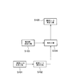
次に、図6を参照して、本実施形態に係る吸収性物品1の製造方法の一部について説明する。なお、図6に記載されていない方法については、既存の方法を用いることができる。吸収性物品の製造方法は、図6に示すように、ステップ101において、表面シート生成工程を行う。具体的には、表面シート10を構成するトップシート11とセカンドシート12とをホットメルト接着剤によって接着する。次いで、トップシート11とセカンドシート12とが接着された表面シート10を、厚み方向Tに圧縮加工し、表面シート圧搾部80を形成する。この圧縮加工は、例えば、加熱及び加圧を行うエンボスロールに、表面シート10を通過させることで、格子状の凹凸加工が形成される。
ステップ102において、表面シート接合工程を行う。具体的には、表面シート10とサイドシート41,42とを、例えば熱溶着によって接着する。
次いで、ステップ103において、吸収体成型工程を行う。具体的には、吸収体の材料となるSAPを不織布で包み、吸収体圧搾部90を形成する。なお、ステップ101及び102の表面シート生成工程及び表面シート接合工程と、ステップ103の吸収体成型工程の順序は、逆の順序であってもよい。
ステップ104において、接合工程を行う。具体的には、ステップ102において生成した表面シート10及びサイドシート41,42と、ステップ103において成型した吸収体30とを接合する接合工程を行う。
ステップ105において、裏面シート接合工程を行う。具体的には、吸収体及び表面シート等と、裏面シート20とを接合する。なお、図6においては、図示しないが、裏面シート20を接合した後、粘着剤を塗布する工程を備える。上記の工程により、本実施の形態に係る吸収性物品を製造することができる。
上述したように、本発明の実施形態を通じて本発明の内容を開示したが、この開示の一部をなす論述及び図面は、本発明を限定するものであると理解すべきではない。この開示から当業者には様々な代替実施の形態、実施例及び運用技術が明らかとなる。
例えば、本実施の形態に係る小領域は、第1直線及び第2直線が等間隔に配置され、第2吸収体圧搾部によって規則的に区画されているが、第2吸収体圧搾部によって区画される小領域は、規則的に配置されていなくてもよい。例えば、第1直線及び第2直線の間隔が異なるように構成され、第2吸収体圧搾部によって区画される小領域が不規則に配置されていてもよい。
<実施例1>
(評価内容)
表面シートの圧搾率が異なる吸収性物品の体液の引き込み性を評価した。実施例1、実施例2及び比較例に係る吸収性物品を用いて、各吸収性物品に人工尿を滴下し、一定時間経過した後の表面シートの水分を指標する表面水分指数を測定し、吸収性物品の体液の引き込み性を評価した。実施例1、実施例2及び比較例に係る吸収性物品は、それぞれ表面シートの圧搾率が異なる。なお、この圧搾率は、表面シート全体の面積に対する表面シート圧搾部の面積である。比較例に係る表面シートの圧搾率は、4.2%であり、実施例1に係る表面シートの圧搾率は、7.5%であり、実施例2に係る表面シートの圧搾率は、12.5%である。
(評価内容)
表面シートの圧搾率が異なる吸収性物品の体液の引き込み性を評価した。実施例1、実施例2及び比較例に係る吸収性物品を用いて、各吸収性物品に人工尿を滴下し、一定時間経過した後の表面シートの水分を指標する表面水分指数を測定し、吸収性物品の体液の引き込み性を評価した。実施例1、実施例2及び比較例に係る吸収性物品は、それぞれ表面シートの圧搾率が異なる。なお、この圧搾率は、表面シート全体の面積に対する表面シート圧搾部の面積である。比較例に係る表面シートの圧搾率は、4.2%であり、実施例1に係る表面シートの圧搾率は、7.5%であり、実施例2に係る表面シートの圧搾率は、12.5%である。
(表面水分指数の測定方法)
U字状の凹み部が形成された下記の使用機器を用いて、使用機器の凹み部の底面に吸収性物品を貼り付けて、吸収性物品の長手方向における中央に下記の条件で人工尿を滴下した。滴下45秒後に試料固定台に吸収性物品を積置し、吸収性物品上にセンサーを置く。滴下1分後にセンサーの水分スキャンを開始し、吸収性物品の表面に残っている水分を指標する表面水分指数を算出した。表面水分指数の測定は、吸収性物品の長手方向中央の1箇所で測定し、かつ中央から長手方向外側に3mmずつずれた4箇所で測定した。合計5箇所の測定値の平均値を算出した。なお、表面水分指数は、電圧(V)×係数(10)-1.5である。
U字状の凹み部が形成された下記の使用機器を用いて、使用機器の凹み部の底面に吸収性物品を貼り付けて、吸収性物品の長手方向における中央に下記の条件で人工尿を滴下した。滴下45秒後に試料固定台に吸収性物品を積置し、吸収性物品上にセンサーを置く。滴下1分後にセンサーの水分スキャンを開始し、吸収性物品の表面に残っている水分を指標する表面水分指数を算出した。表面水分指数の測定は、吸収性物品の長手方向中央の1箇所で測定し、かつ中央から長手方向外側に3mmずつずれた4箇所で測定した。合計5箇所の測定値の平均値を算出した。なお、表面水分指数は、電圧(V)×係数(10)-1.5である。
(測定条件)
・使用機器・・静電容量型水分計
・人工尿滴下量・・10ml
・人工尿滴下速度・・60ml/min
・測定前のセンサーの電圧・・・0.15V
・センサーの荷重・・・9g/cm2
(評価結果)
評価結果を表1に示す。

・使用機器・・静電容量型水分計
・人工尿滴下量・・10ml
・人工尿滴下速度・・60ml/min
・測定前のセンサーの電圧・・・0.15V
・センサーの荷重・・・9g/cm2
(評価結果)
評価結果を表1に示す。
実施例1及び実施例2に係る吸収性物品の表面水分指数は、いずれも10以下である。一方、比較例に係る吸収性物品は、10を超えている。なお、表面水分指数は、数値が高い程、濡れ感が高いことを示している。表面水分指数は、官能テストによる濡れ感に対応付けられている。5以下の表面水分指数は、表面シートを手で触った際に水分を全く感じないレベルである。5より高く10以下の表面水分指数は、表面シートを手で触った際に少し水分を感じるが不快ではないレベルである。10より高く20以下の表面水分指数は、表面シートを手で触った際に不快に感じる人がいるレベルである。20以上の表面水分指数は、表面シートを手で触った際に非常に不快に感じるレベルである。
実施例1及び実施例2に係る吸収性物品の表面水分指数は、いずれも10以下であり、高い体液の引き込み性を有することがわかった。体液の引き込み性を維持する観点から、表面シートの圧搾率は、7.5%以上が望ましい。一方、表面シートの圧搾率が高すぎると、表面シートの剛性が高くなり過ぎ、身体の動きに追従して変形し難くなる。柔軟性を確保する観点から、表面シートの圧搾率は、50%以下が望ましい。
<実施例2>
(評価内容)
実施例に係る本実施の形態の吸収性物品と、比較例1~比較例5に係る従来の吸収性物品との変形し易さを評価した。具体的には、実施例に係る吸収性物品と、比較例1~比較例5に係る吸収性物品との試料を下記のトルク試験機を用いて、回転方向に捻るように変形させて、その際の応力であるトルク値に基づいて変形し易さを評価した。
(評価内容)
実施例に係る本実施の形態の吸収性物品と、比較例1~比較例5に係る従来の吸収性物品との変形し易さを評価した。具体的には、実施例に係る吸収性物品と、比較例1~比較例5に係る吸収性物品との試料を下記のトルク試験機を用いて、回転方向に捻るように変形させて、その際の応力であるトルク値に基づいて変形し易さを評価した。
(トルク値の測定方法)
各吸収性物品に係る試料を採取する。試料は、試料の長手方向が吸収性物品の搬送方向MDに沿うMD試料と、試料の長手方向が搬送方向と交差する交差方向CDに沿うCD試料とを用意する。MD試料は、吸収性物品を伸長させた状態にして、長手方向における中央に印を付す。中央の印から長手方向外側に25mmずつ離間した位置に、十字の印を入れる。次いで、十字印から長手方向外側に35mmずつ離間した位置に線を引き、この線の位置で切断する。切断した試料の長手方向における中央が下着のクロッチの中央に合うようにして、試料を下着に貼り付ける。
各吸収性物品に係る試料を採取する。試料は、試料の長手方向が吸収性物品の搬送方向MDに沿うMD試料と、試料の長手方向が搬送方向と交差する交差方向CDに沿うCD試料とを用意する。MD試料は、吸収性物品を伸長させた状態にして、長手方向における中央に印を付す。中央の印から長手方向外側に25mmずつ離間した位置に、十字の印を入れる。次いで、十字印から長手方向外側に35mmずつ離間した位置に線を引き、この線の位置で切断する。切断した試料の長手方向における中央が下着のクロッチの中央に合うようにして、試料を下着に貼り付ける。
CD試料は、吸収性物品を伸長させた状態にして、長手方向における中央に印を付す。中央の印から幅方向外側に25mmずつ離間した位置に、十字の印を入れる。次いで、試料の長手方向における中央が下着のクロッチの中央に合うようにして、試料を下着に貼り付ける。
トルク試験機を用いて、各試料の一方の十字の印がチャック内側端部になるように上部チャックで挟むとともに、他方の十字の印がチャック内側端部になるように下部チャックで挟む。なお、このとき、チャックの中央が試料の十字の長手方向の線上に重なるように配置する。チャック間におけるMD試料の長さ寸法は、50mmであり、チャック間におけるCD試料の長さ寸法は、30mmである。
MD試料は、吸収性物品の長手方向に沿った軸を中心とした回転方向に試料を捻り、試料に係る応力を測定する。CD試料は、吸収性物品の幅方向に沿った軸を中心とした回転方向に試料を捻り、試料に係る応力を測定する。回転方向の捻りは、一旦下記の回転角度まで捻った後、反対方向に回転させる(捻りがない状態に戻す)。トルク値は、変形していない状態から下記の回転角度まで捻るように回転させた際に測定する。MD試料のトルク値を測定し、かつCD試料のトルク値を測定し、これらのトルク値の平均値を、各吸収性物品のトルク値とした。
(試験条件)
・回転速度・・・MD試料:30rpm、CD試料:30rpm
・回転角度(反転位置の角度)・・・MD試料:50°、CD試料:65°
・測定角度・・・MD試料:45°、CD試料:60°
・回転回数・・・1回転
(評価結果)
評価結果を表2に示す。

・回転速度・・・MD試料:30rpm、CD試料:30rpm
・回転角度(反転位置の角度)・・・MD試料:50°、CD試料:65°
・測定角度・・・MD試料:45°、CD試料:60°
・回転回数・・・1回転
(評価結果)
評価結果を表2に示す。
比較例1から比較例5のトルク値は、いずれも20Nを超えている。一方、実施例のトルク値は、16.8Nであり、比較例に係るトルク値と比べて、非常に小さく、回転方向に向かう捻り対して変形し易いことがわかった。
なお、日本国特許出願第2011-130742号(2011年6月10日出願)の全内容が、参照により、本願明細書に組み込まれている。
吸収性物品は、着用者の動きによる外力が作用した際に、表面シート圧搾部や吸収体圧搾部を起点として、表面シート圧搾部や吸収体圧搾部が形成されていない部分を変形させることができる。表面シート圧搾部の配置パターンと、吸収体圧搾部の配置パターンとは、異なっているため、表面シート圧搾部と吸収体圧搾部との組み合わせにより、吸収性物品全体において圧搾された領域を不規則的に配置することができる。表面シート全体が均一に圧搾されている吸収性物品と比較して、不規則な動きにも追従して変形し易く、着用時の違和感を低減できる吸収性物品を提供できる。
表面シートには、間欠的に複数の表面シート圧搾部が形成されており、表面シート上に付着した体液は、表面シート圧搾部によって速やかに表面シート内に引き込まれる。表面シート圧搾部の下方には、吸収体圧搾部が形成された領域又は吸収体圧搾部が形成されていない領域が配置されている。また、吸収体圧搾部が形成されていない領域が表面シート圧搾部の下方に配置された部分では、表面シートから吸収体に引き込んだ体液を、吸収体圧搾部が形成されていない領域において保持することができる。また、吸収体に一旦移行した体液は、高吸収性ポリマーによって保持されて着用者側に移行しない。よって、吸収体の厚みを抑えつつ、体液の引き込み性を高め、かつ体液の逆戻りを防止することができる吸収性物品を提供できる。
C1…第1直線、 C2…第2直線、 C3…第3直線、 C4…第4直線、 CA…中央領域、 L…長手方向、 LA…長手方向外側領域、 R1…第1領域、 R2…第2領域、 T…厚み方向、 W…幅方向、 1…吸収性物品、 10…表面シート、 20…裏面シート、 30…吸収体、 31…小領域、 41,42…サイドシート、 50…粘着材、 80…表面シート圧搾部、 81…第1表面シート圧搾部、 82…第2表面シート圧搾部、 83…第3表面シート圧搾部、 90…吸収体圧搾部、 91…第1吸収体圧搾部、 92…第2吸収体圧搾部
Claims (9)
- 液透過性の表面シート、液不透過性の裏面シート、及び前記表面シートと前記裏面シートとの間に配置される吸収体を備える吸収性物品であって、
前記吸収体には、厚み方向に圧搾された吸収体圧搾部が形成され、
前記表面シートには、厚み方向に圧搾された表面シート圧搾部が間欠的に複数形成され、
前記吸収体は、前記吸収体圧搾部によって区画された小領域を有しており、
前記小領域には、高吸収性ポリマー粒子がそれぞれ配置されており、
前記厚み方向において、前記小領域にはそれぞれ前記表面シート圧搾部が重なっており、
前記小領域は、第1小領域と、第2小領域とを備えており、前記第1小領域に重なる前記表面シート圧搾部の配置パターンと、前記第2小領域に重なる前記表面シート圧搾部の配置パターンとは、異なるように構成されている、吸収性物品。 - 前記吸収性物品は、前記吸収性物品の長手方向における中央に位置する中央領域と、前記中央領域よりも前記長手方向外側に位置する長手方向外側領域と、を有しており、
前記小領域の面積に対する前記表面シート圧搾部の面積の比率である圧搾率は、前記中央領域に位置する前記小領域よりも、前記長手方向外側領域に位置する前記小領域の方が高い、請求項1に記載の吸収性物品。 - 前記吸収体圧搾部は、格子状に配置されている、請求項1又は請求項2に記載の吸収性物品。
- 前記吸収体圧搾部は、間欠的に複数形成されている、請求項1から請求項3のいずれかに記載の吸収性物品。
- 前記表面シート圧搾部は、第1表面シート圧搾部と、前記第1表面シート圧搾部よりも面積が大きい第2表面シート圧搾部と、を備える、請求項1から請求項4のいずれかに記載の吸収性物品。
- 前記小領域には、前記第1表面シート圧搾部と、前記第2表面シート圧搾部とがそれぞれ重なって配置されている、請求項5に記載の吸収性物品。
- 前記小領域は、前記吸収体圧搾部に隣接した第1領域と、前記吸収体圧搾部から離間した第2領域とを有しており、
前記第1領域の面積に対する前記第1領域に重なる前記表面シート圧搾部の面積である圧搾比率は、前記第2領域の面積に対する前記第2領域に重なる前記表面シート圧搾部の面積である圧搾比率よりも高い、請求項1から請求項6のいずれかに記載の吸収性物品。 - 前記吸収体圧搾部は、前記表面シートを介して前記吸収体圧搾部が視認可能に構成されている、請求項1から請求項7のいずれかに記載の吸収性物品。
- 液透過性の表面シート、液不透過性の裏面シート、及び前記表面シートと前記裏面シートとの間に配置される吸収体を備える吸収性物品であって、
前記吸収体には、厚み方向に圧搾された吸収体圧搾部が形成され、
前記表面シートには、厚み方向に圧搾された表面シート圧搾部が間欠的に複数形成され、
前記吸収体は、前記吸収体圧搾部によって区画された小領域を有しており、
前記小領域には、高吸収性ポリマー粒子がそれぞれ配置されており、
前記厚み方向において、前記小領域にはそれぞれ前記表面シート圧搾部が重なっており、
前記吸収体圧搾部は、前記表面シートを介して視認可能に構成されている、吸収性物品。
Applications Claiming Priority (2)
| Application Number | Priority Date | Filing Date | Title |
|---|---|---|---|
| JP2011130742A JP5797469B2 (ja) | 2011-06-10 | 2011-06-10 | 吸収性物品 |
| JP2011-130742 | 2011-06-10 |
Publications (1)
| Publication Number | Publication Date |
|---|---|
| WO2012169576A1 true WO2012169576A1 (ja) | 2012-12-13 |
Family
ID=47296133
Family Applications (1)
| Application Number | Title | Priority Date | Filing Date |
|---|---|---|---|
| PCT/JP2012/064654 Ceased WO2012169576A1 (ja) | 2011-06-10 | 2012-06-07 | 吸収性物品 |
Country Status (3)
| Country | Link |
|---|---|
| JP (1) | JP5797469B2 (ja) |
| TW (1) | TWI520717B (ja) |
| WO (1) | WO2012169576A1 (ja) |
Cited By (4)
| Publication number | Priority date | Publication date | Assignee | Title |
|---|---|---|---|---|
| JP2016214407A (ja) * | 2015-05-15 | 2016-12-22 | 王子ホールディングス株式会社 | 吸収性物品 |
| US20200100956A1 (en) * | 2018-09-27 | 2020-04-02 | The Procter & Gamble Company | Nonwoven webs with visually discernible patterns |
| US20200345563A1 (en) * | 2019-05-03 | 2020-11-05 | The Procter & Gamble Company | Nonwoven webs with one or more repeat units |
| US11110196B2 (en) | 2013-08-01 | 2021-09-07 | The Procter & Gamble Company | Articles comprising malodor reduction compositions |
Families Citing this family (17)
| Publication number | Priority date | Publication date | Assignee | Title |
|---|---|---|---|---|
| US9566198B2 (en) * | 2013-03-15 | 2017-02-14 | Dsg Technology Holdings Ltd. | Method of making an absorbent composite and absorbent articles employing the same |
| US9789014B2 (en) | 2013-03-15 | 2017-10-17 | Dsg Technology Holdings Ltd. | Method of making an absorbent composite and absorbent articles employing the same |
| JP2014198075A (ja) * | 2013-03-29 | 2014-10-23 | 日本製紙クレシア株式会社 | 絵柄付き吸収性物品 |
| JP6296599B2 (ja) * | 2013-11-29 | 2018-03-20 | 日本製紙クレシア株式会社 | 吸収性物品 |
| JP2015112340A (ja) * | 2013-12-12 | 2015-06-22 | 花王株式会社 | 吸収性物品の表面シート及び吸収性物品 |
| JP2016214405A (ja) * | 2015-05-15 | 2016-12-22 | 王子ホールディングス株式会社 | 吸収性物品 |
| NZ732546A (en) * | 2014-12-10 | 2018-05-25 | Oji Holdings Corp | Absorbent article |
| TWI607745B (zh) * | 2015-05-15 | 2017-12-11 | Oji Holdings Corp | Absorbent article, and its manufacturing apparatus and manufacturing method |
| JP6558281B2 (ja) * | 2016-03-08 | 2019-08-14 | 王子ホールディングス株式会社 | 吸収性物品、その製造装置および製造方法 |
| JP6413921B2 (ja) * | 2015-05-15 | 2018-10-31 | 王子ホールディングス株式会社 | 吸収性物品 |
| CN107949360B (zh) * | 2015-09-04 | 2021-06-25 | 王子控股株式会社 | 吸收性物品 |
| JP6842886B2 (ja) * | 2016-11-15 | 2021-03-17 | 花王株式会社 | 吸収性物品 |
| JP6492204B2 (ja) * | 2018-03-15 | 2019-03-27 | 花王株式会社 | 吸収性物品用の表面シート |
| JP7158923B2 (ja) * | 2018-07-02 | 2022-10-24 | ユニ・チャーム株式会社 | 吸収性物品包装体 |
| JP7822731B2 (ja) * | 2021-09-21 | 2026-03-03 | 小林製薬株式会社 | 体液吸収性物品 |
| JP7822732B2 (ja) * | 2021-09-21 | 2026-03-03 | 小林製薬株式会社 | 体液吸収性物品 |
| JP2024091080A (ja) * | 2022-12-23 | 2024-07-04 | 小林製薬株式会社 | 体液吸収シート |
Citations (4)
| Publication number | Priority date | Publication date | Assignee | Title |
|---|---|---|---|---|
| JP2003230593A (ja) * | 2002-02-12 | 2003-08-19 | Daio Paper Corp | 生理用ナプキン |
| JP2009512489A (ja) * | 2005-10-26 | 2009-03-26 | ザ プロクター アンド ギャンブル カンパニー | 特定の領域の疎水性を増大させるインクを備えた衛生物品 |
| JP2010148708A (ja) * | 2008-12-25 | 2010-07-08 | Uni Charm Corp | 薄型吸収性物品 |
| JP2010527682A (ja) * | 2007-05-25 | 2010-08-19 | ザ プロクター アンド ギャンブル カンパニー | 印刷パターンとエンボスパターンとを有する婦人衛生物品 |
-
2011
- 2011-06-10 JP JP2011130742A patent/JP5797469B2/ja not_active Expired - Fee Related
-
2012
- 2012-06-04 TW TW101119957A patent/TWI520717B/zh active
- 2012-06-07 WO PCT/JP2012/064654 patent/WO2012169576A1/ja not_active Ceased
Patent Citations (4)
| Publication number | Priority date | Publication date | Assignee | Title |
|---|---|---|---|---|
| JP2003230593A (ja) * | 2002-02-12 | 2003-08-19 | Daio Paper Corp | 生理用ナプキン |
| JP2009512489A (ja) * | 2005-10-26 | 2009-03-26 | ザ プロクター アンド ギャンブル カンパニー | 特定の領域の疎水性を増大させるインクを備えた衛生物品 |
| JP2010527682A (ja) * | 2007-05-25 | 2010-08-19 | ザ プロクター アンド ギャンブル カンパニー | 印刷パターンとエンボスパターンとを有する婦人衛生物品 |
| JP2010148708A (ja) * | 2008-12-25 | 2010-07-08 | Uni Charm Corp | 薄型吸収性物品 |
Cited By (7)
| Publication number | Priority date | Publication date | Assignee | Title |
|---|---|---|---|---|
| US11110196B2 (en) | 2013-08-01 | 2021-09-07 | The Procter & Gamble Company | Articles comprising malodor reduction compositions |
| JP2016214407A (ja) * | 2015-05-15 | 2016-12-22 | 王子ホールディングス株式会社 | 吸収性物品 |
| US20200100956A1 (en) * | 2018-09-27 | 2020-04-02 | The Procter & Gamble Company | Nonwoven webs with visually discernible patterns |
| US11998427B2 (en) * | 2018-09-27 | 2024-06-04 | The Procter & Gamble Company | Nonwoven webs with visually discernible patterns |
| US20200345563A1 (en) * | 2019-05-03 | 2020-11-05 | The Procter & Gamble Company | Nonwoven webs with one or more repeat units |
| US11999150B2 (en) * | 2019-05-03 | 2024-06-04 | The Procter & Gamble Company | Nonwoven webs with one or more repeat units |
| US12043019B2 (en) | 2019-05-03 | 2024-07-23 | The Procter & Gamble Company | Nonwoven webs with one or more repeat units |
Also Published As
| Publication number | Publication date |
|---|---|
| TWI520717B (zh) | 2016-02-11 |
| JP2013000141A (ja) | 2013-01-07 |
| TW201311222A (zh) | 2013-03-16 |
| JP5797469B2 (ja) | 2015-10-21 |
Similar Documents
| Publication | Publication Date | Title |
|---|---|---|
| JP5797469B2 (ja) | 吸収性物品 | |
| TWI358283B (en) | Process of producing an absorbent article | |
| TWI637735B (zh) | Absorbent article | |
| EP3123993B1 (en) | Method for producing absorbent article and absorbent article | |
| RU2620746C2 (ru) | Впитывающее изделие, включающее по меньшей мере две сложенные друг на друга индивидуальные поглощающие прокладки | |
| JP2003024372A (ja) | 吸収性物品 | |
| JP7149771B2 (ja) | 吸収体 | |
| JP6140388B2 (ja) | シート及びこれを用いた吸収性物品 | |
| JP6375354B2 (ja) | 吸収性物品 | |
| JP7015685B2 (ja) | 吸収性物品 | |
| JP5883681B2 (ja) | 吸収性物品 | |
| WO2013154087A1 (ja) | 吸収性物品 | |
| JP2018086170A5 (ja) | ||
| JP2014064631A (ja) | 吸収性物品 | |
| JP6604777B2 (ja) | 吸収性物品 | |
| JP7411430B2 (ja) | 吸収体及び吸収性物品 | |
| JP5816022B2 (ja) | 吸収性物品 | |
| JP7475918B2 (ja) | 吸収性物品 | |
| JP6342765B2 (ja) | 使い捨て紙おむつ | |
| JP2013074934A (ja) | 吸収性物品 | |
| JP5374301B2 (ja) | 陰唇間パッド | |
| CN114786638B (zh) | 吸收体和吸收性物品 | |
| JP7578394B2 (ja) | 吸収性物品 | |
| JP7164370B2 (ja) | 吸収性物品 | |
| JP6851349B2 (ja) | 吸収体 |
Legal Events
| Date | Code | Title | Description |
|---|---|---|---|
| 121 | Ep: the epo has been informed by wipo that ep was designated in this application |
Ref document number: 12797456 Country of ref document: EP Kind code of ref document: A1 |
|
| NENP | Non-entry into the national phase |
Ref country code: DE |
|
| 122 | Ep: pct application non-entry in european phase |
Ref document number: 12797456 Country of ref document: EP Kind code of ref document: A1 |