WO2012169357A1 - 植物工場用の採光装置および植物の育成方法 - Google Patents
植物工場用の採光装置および植物の育成方法 Download PDFInfo
- Publication number
- WO2012169357A1 WO2012169357A1 PCT/JP2012/063217 JP2012063217W WO2012169357A1 WO 2012169357 A1 WO2012169357 A1 WO 2012169357A1 JP 2012063217 W JP2012063217 W JP 2012063217W WO 2012169357 A1 WO2012169357 A1 WO 2012169357A1
- Authority
- WO
- WIPO (PCT)
- Prior art keywords
- light
- plant factory
- daylighting
- silver
- plant
- Prior art date
- Legal status (The legal status is an assumption and is not a legal conclusion. Google has not performed a legal analysis and makes no representation as to the accuracy of the status listed.)
- Ceased
Links
Images

Classifications
-
- A—HUMAN NECESSITIES
- A01—AGRICULTURE; FORESTRY; ANIMAL HUSBANDRY; HUNTING; TRAPPING; FISHING
- A01G—HORTICULTURE; CULTIVATION OF VEGETABLES, FLOWERS, RICE, FRUIT, VINES, HOPS OR SEAWEED; FORESTRY; WATERING
- A01G9/00—Cultivation in receptacles, forcing-frames or greenhouses; Edging for beds, lawn or the like
- A01G9/24—Devices or systems for heating, ventilating, regulating temperature, illuminating, or watering, in greenhouses, forcing-frames, or the like
- A01G9/249—Lighting means
-
- A—HUMAN NECESSITIES
- A01—AGRICULTURE; FORESTRY; ANIMAL HUSBANDRY; HUNTING; TRAPPING; FISHING
- A01G—HORTICULTURE; CULTIVATION OF VEGETABLES, FLOWERS, RICE, FRUIT, VINES, HOPS OR SEAWEED; FORESTRY; WATERING
- A01G7/00—Botany in general
- A01G7/04—Electric or magnetic or acoustic treatment of plants for promoting growth
- A01G7/045—Electric or magnetic or acoustic treatment of plants for promoting growth with electric lighting
Definitions
- the present invention relates to a daylighting apparatus for a plant factory and a plant growing method.
- An object of the present invention is to provide a daylighting device for plant factories capable of growing plants efficiently and efficiently at low cost. Another object of the present invention is to provide a plant growing method using such a daylighting apparatus.
- a daylighting device for a plant factory having a daylighting unit that takes in natural light and a light emitting unit that irradiates the plant factory with light taken from the daylighting unit, and has silver on the inner surface. Or a light reflecting layer made of a silver alloy, and the light taken from the daylighting unit is reflected at least once by the light reflecting layer and then irradiated from the light emitting unit into the plant factory;
- a daylighting device for a plant factory wherein the ratio of the photon in the near infrared region having a wavelength of 700 to 1000 nm in the light irradiated from the light part into the plant factory is 40% or more.
- a diffuser plate for diffusing the light taken from the daylighting unit is provided in the light emitting unit.
- a method for growing a plant in a plant factory using a daylighting device capable of taking natural light and irradiating the taken light into the plant factory wherein the daylighting device has an inner surface. And a light reflecting layer made of silver or a silver alloy, and the light taken into the daylighting device is reflected at least once by the light reflecting layer, and is then introduced into the plant factory at a wavelength of 700 to 1000 nm.
- a method for growing a plant characterized by irradiating with natural light having an infrared photon ratio of 40% or more.
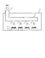
- FIG. 1 is a schematic diagram illustrating the overall configuration of a plant factory according to the present embodiment.
- FIG. 2 is a diagram illustrating a configuration of a reflecting plate included in the daylighting apparatus according to the embodiment.
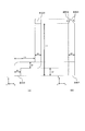
- FIG. 3A and FIG. 3B are diagrams illustrating the configuration of the daylighting device used in the example.
- FIG. 1 is a schematic diagram showing an overall configuration of a plant factory 1 according to the present embodiment.
- a plant factory 1 according to the present embodiment is a plant factory that uses, for example, a frozen container, an empty store, an abandoned factory, etc. as a closed space, and irradiates the plant factory 1 with sunlight.
- the lighting device 10 is provided.
- the daylighting apparatus 10 takes in sunlight from the daylighting port 11, and reflects the taken-in light by a light reflection layer (a light reflection layer will be described later) formed on the inner surface of the daylighting apparatus 10, while the daylighting apparatus 10 10 is configured to irradiate the plant factory 1 with the light guided and guided to the inside of the plant factory 1. And as shown in FIG. 1, the light from each light emission port 12 will be irradiated to the cultivation container 20 in which the plant 30 installed in the plant factory 1 was planted.
- the plant factory 1 it can be used for any cultivation method of hydroponics and artificial soil cultivation.
- the lighting device 10 in order to take in sunlight efficiently, you may provide the sunlight tracking device for tracking sunlight, and condensing apparatuses, such as a condensing lens.
- the daylighting device 10 is formed by molding a light reflecting plate having a light reflecting layer on the inner layer into a predetermined shape, and the sun taken from the lighting port 11 by the light reflecting layer formed on the inner surface. Light is reflected.
- the lighting port 11 and the light emission port 12 can be comprised with a highly transparent board which can permeate
- the light emission port 12 may be an opening without providing such a highly transparent plate.
- the daylighting apparatus 10 has a bent portion as shown in FIG. 1, so that the sunlight taken in from the daylighting port 11 is provided on the inner surface of the daylighting apparatus 10 at least once, preferably twice or more. After being reflected by the formed light reflecting layer, the plant factory 1 is irradiated from the light exit 12.
- a diffusion plate may be installed on the surface facing the light emission port 12, and the plant factory 1 is irradiated from the light emission port 12 by installing the diffusion plate.
- the light that is emitted can be made soft. Or in this embodiment, it may replace with a highly transparent board in the light emission port 12, and you may install a diffuser plate, and also in this case, the light irradiated in the plant factory 1 from the light emission port 12 is soft. Can be.
- FIG. 2 is a diagram showing a configuration of a light reflecting plate that constitutes the daylighting apparatus 10 of the present embodiment.
- the light reflecting plate constituting the daylighting apparatus 10 of the present embodiment is formed by laminating the base 100, the resin layer 110, the light reflecting layer 120, and the protective layer 130 in this order. Yes. 2 is disposed in the daylighting apparatus 10 so that the light reflection layer 120 and the protective layer 130 are on the inner surface side.
- the substrate 100 may be made of a material that can be processed into a desired shape, but in the present embodiment, a metal plate is used in terms of excellent workability. Further, the metal plate constituting the substrate 100 is not particularly limited, and examples thereof include a steel plate, an aluminum plate, an aluminum alloy plate, etc. Among these, a steel plate is used in terms of improving mechanical strength and reducing manufacturing costs. Preferably used.
- the steel plate examples include an iron alloy plate having a chromium content of less than 11% by mass, or an iron alloy having a chromium content of 11% by mass or more, a so-called stainless steel plate.
- an iron alloy steel sheet having a chromium content of less than 11% by mass is an inexpensive material compared to aluminum and stainless steel, and is therefore suitable for widespread use of products.
- the aluminum alloy plate is made of aluminum as a main component and is alloyed by adding magnesium (Mg), manganese (Mn), silicon (Si) or the like in order to impart strength, workability, corrosion resistance and the like.
- the metal plate for constituting the base body 100 may be a surface-treated metal plate subjected to surface treatment.
- the surface-treated metal plate include those obtained by subjecting the surface of the metal plate to various platings, and those obtained by subjecting the surface of an aluminum plate to an alumite treatment.
- the substrate 100 is a plated metal plate that has been surface-treated by plating
- zinc, zinc alloy, tin, nickel, chromium, or the like can be used as the metal used for plating.
- a galvanized steel sheet obtained by forming zinc plating or zinc alloy plating on a steel sheet as the substrate 100 for example, a hot dip galvanized steel sheet, a hot dip galvanized steel sheet, There are a plurality of types such as an electrogalvanized steel sheet and an electrogalvanized steel sheet.
- zinc or zinc alloy is used as a metal used for plating.
- zinc alloy zinc (Zn) containing 5-55 mass% aluminum (Al), zinc (Zn) containing cobalt (Co), molybdenum (Mo), or the like is used.
- the galvanized steel sheet may be subjected to a chemical conversion treatment in order to prevent peeling or alteration of the plating such as zinc.
- a chemical conversion treatment examples include chromate treatment, phosphate treatment, lithium-silicate treatment, silane coupling treatment, and zirconium treatment.
- the thickness of the substrate 100 is not particularly limited, but is usually 0.2 to 1 mm, preferably 0.3 to 0.8 mm.
- the resin layer 110 is provided in order to improve the corrosion resistance of the base body 100 itself, and to improve the adhesion between the base body 100 and the light reflection layer 120 by being interposed between the base body 100 and the light reflection layer 120.
- the resin layer 110 can be a coating film or film made of various materials.
- the material of the coating film is not particularly limited as long as it is an organic resin material having good adhesion to the substrate 100.
- a polyester resin, an alkyd resin, an acrylic resin, and a two-component curing type A paint such as polyurethane resin is suitable.
- the film material include polyethylene, polycarbonate resin, polyamide resin, and polyimide resin.
- the resin layer 110 When the resin layer 110 is formed of a paint film, it can be formed on the substrate 100 by a coating method using a paint in which a material is dissolved. Moreover, when forming the resin layer 110 with a film, it can be produced on the substrate 100 by attaching the film to the substrate 100 with an adhesive or the like.
- the light reflecting layer 120 is a layer made of silver or a silver alloy. Since silver has a high reflectance in the visible light region among elements, it is preferable from the viewpoint of increasing the reflection efficiency of the light reflecting plate.
- the light reflecting layer 120 is a layer made of silver or a silver alloy, so that when the light taken into the daylighting apparatus 10 is reflected, the near infrared wavelength region is 700 to 1000 nm.
- the sunlight taken in from the daylighting port 11 shown in FIG. 1 is guided into the daylighting apparatus 10 while being reflected by the light reflection layer 120, and the guided light is emitted from the light emission port 12.
- the ratio of the photon in the near-infrared region with a wavelength of 700 to 1000 nm in the light irradiated into the plant factory 1 from the light emission port 12 when irradiated from above is preferably 40% or more, more preferably 50% or more. It can be done. As a result, the growth of the plant 30 in the daylighting device 20 installed in the plant factory 1 can be promoted.
- the sunlight taken into the daylighting apparatus 10 usually contains near-infrared light having a wavelength of 700 to 1000 nm at a rate of 50 to 70%.
- an artificial light source such as a fluorescent lamp
- the wavelength of light emitted from the artificial light source is usually in a photosynthesis effective wavelength region. Since it is ⁇ 700 nm and does not contain light in the near infrared wavelength range of 700 to 1000 nm, plant growth was insufficient.
- an artificial light source such as a fluorescent lamp contains light in the wavelength range of 700 to 1000 nm in addition to light in the wavelength range of 400 to 700 nm, or supplemented with an artificial light source, the cost will increase significantly. There are also challenges.
- the light reflection layer of the daylighting apparatus conventionally used aluminum or aluminum alloy
- the reflection efficiency is relatively high, there is an absorption peak peculiar to aluminum near 800 nm
- the light reflection layer of the daylighting device is formed of aluminum or an aluminum alloy
- the light taken into the daylighting device is reflected by the light reflection layer, so that light in the wavelength region of 700 to 1000 nm is attenuated.
- a daylighting device in which the light reflecting layer is formed of aluminum or an aluminum alloy attenuates light in the wavelength range of 700 to 1000 nm. Therefore, when used for a plant factory, plant growth is insufficient. There was a problem of becoming.
- the light reflecting layer 120 constituting the lighting device 10 is formed of a layer made of silver or a silver alloy, so that the light taken from the lighting port 11 is reflected by the light reflecting layer 120. Even in such a case, it is possible to prevent the attenuation of light in the wavelength range of 700 to 1000 nm, thereby solving the conventional problems described above, thereby promoting the growth of plants.
- Such a light reflection layer 120 can be formed by an electroless plating method in which silver is reduced and precipitated by a silver mirror reaction, for example, a spray plating method.
- it can be formed by an electroplating method in which electrolysis is performed in an aqueous solution containing silver ions, an evaporation method in which silver is evaporated in a reduced pressure atmosphere to form a film.
- the thickness of the light reflecting layer 120 is preferably 0.01 to 0.3 ⁇ m, more preferably 0.08 to 0.15 ⁇ m. If the thickness of the light reflecting layer 120 is too thin, pinholes are generated and the reflectance may be reduced. On the other hand, if the thickness of the light reflection layer 120 is too thick, a desired glossy surface cannot be obtained, and the reflectance may be lowered. Also, from the economical viewpoint, it is not desirable that the thickness of the light reflecting layer 120 is too thick.
- the light reflecting layer 120 is made of a silver alloy
- an alloy mainly containing silver may be used, but the silver content in the silver alloy is preferably 97% by weight or more, and more Preferably it is 99 weight% or more.
- the protective layer 130 is a layer for protecting the light reflecting layer 120. Since the light reflecting layer 120 is made of silver or a silver alloy, the light reflecting layer 120 is likely to be discolored or contaminated when exposed to the atmosphere. In particular, the light reflecting layer 120 has a property of being easily discolored when the atmosphere contains a trace amount of a sulfur-based gas. . In addition, when cleaning dust and dirt adhering to the light reflecting layer 120, the light reflecting layer 120 also has a property of easily leaving a color change mark due to a detergent. Therefore, the protective layer 130 is a layer provided on the light reflecting layer 120 in order to prevent these, and by providing the protective layer 130, it is possible to maintain the performance and maintain the lighting device 10 over a long period of time.
- the protective layer 130 uses a film made of an organic resin material, an inorganic material, or a mixture thereof. Or you may comprise in two layers of the film
- the organic resin material any material that is transparent and can be thinned may be used.
- a polyester resin, an acrylic resin, a silicone resin, or the like can be used.
- the inorganic material titanium oxide or the like excellent in contamination resistance can be used.
- the protective layer 130 may be manufactured by a coating method using a coating solution in which an organic resin material is dissolved or a method in which an organic resin material is attached in a film shape. it can.
- the protective layer 130 may be an increased reflection film.
- the increased reflection film is formed by laminating a layer made of a material with a large refractive index such as titanium oxide and a layer made of a material with a small refractive index such as silicon oxide into two layers, and the optical thickness of each layer.
- the thickness (physical film thickness ⁇ refractive index) is ⁇ / 4 ( ⁇ : wavelength of light), and the entire optical thickness is ⁇ / 2.
- the thickness of the protective layer 130 is preferably 1 to 15 ⁇ m, more preferably 3 to 10 ⁇ m. If the thickness of the protective layer 130 is too thin, the protective effect of the light reflecting layer 120 is reduced, and the light reflecting layer 120 may be discolored or may be easily contaminated. On the other hand, if the thickness of the protective layer 130 is too thick, the reflectance may decrease. *
- a metal plate for constituting the base body 100 is prepared, and a resin layer 110 is formed on the surface of the metal plate.
- the resin layer 110 is formed by applying a coating method using a paint in which a material for forming the resin layer 110 is dissolved on the base 100 or a film made of the material for forming the resin layer 110 to the base 100 with an adhesive or the like. It can be formed by a method of attaching.
- a light reflection layer 120 made of silver or a silver alloy is formed on the surface of the resin layer 110 formed on the substrate 100. Below, the method to form the light reflection layer 120 which consists of silver by the electroless-plating method is demonstrated.
- the surface of the resin layer 110 is subjected to corona discharge treatment or glow discharge treatment.
- an aqueous solution (pretreatment solution) containing stannic chloride, stannous chloride and ferric chloride containing hydrochloric acid is applied to the surface of the resin layer 110, so that tin as a catalyst is added to the resin layer 110. Form on the surface.
- the surface of the resin layer 110 on which tin is formed is cleaned using ion-exchanged water or distilled water, and the pretreatment solution remaining on the surface of the resin layer 110 is removed.
- an aqueous silver nitrate solution is applied to the surface of the resin layer 110.
- the silver deposited on the surface of the resin layer 110 replaces the tin formed using the pretreatment solution, and a silver starting nucleus is formed.
- the surface of the resin layer 110 is washed with ion-exchanged water or distilled water, and the excess silver nitrate aqueous solution remaining on the surface of the resin layer 110 is removed.
- an aqueous ammoniacal silver nitrate solution having a pH of 10 to 13 and a reducing agent aqueous solution having a pH of 8 to 12 containing a reducing agent for example, hydrazinium sulfate, glyoxal, etc.
- a reducing agent for example, hydrazinium sulfate, glyoxal, etc.
- the reducing agent aqueous solution an aqueous solution obtained by dissolving or diluting the reducing agent in water and adding alkali to sodium hydroxide is used.
- the light reflecting layer 120 made of silver is formed using silver formed on the surface of the resin layer 110 as a starting nucleus.
- cleaning is performed using ion-exchanged water or distilled water to remove the ammoniacal silver nitrate aqueous solution and the reducing agent aqueous solution remaining on the surface of the light reflecting layer 120, and the air is blown to adhere to the surface of the light reflecting layer 120. Blow off the water droplets, and then dry. Drying conditions can be 70 degreeC and 20 minutes, for example.
- the light reflecting layer 120 when forming the light reflection layer 120, an immersion method may be used instead of the above-described spray injection method, and further, instead of the above-described electroless plating method,
- the light reflecting layer 120 may be formed by a conventionally known electroplating method or vapor deposition method.
- the protective layer 130 is formed on the light reflecting layer 120.
- the protective layer 130 can be formed by applying a solution for a protective layer containing a resin that constitutes the protective layer 130 on the light reflecting layer 120 and drying it.
- the drying temperature is preferably 70 to 120 ° C., more preferably 80 to 100 ° C.
- the drying time is preferably 20 to 90 minutes, more preferably 30 to 60 minutes.
- the light reflector constituting the daylighting apparatus 10 of the present embodiment is manufactured.
- the lighting apparatus 10 of this embodiment is equipped with the light reflection layer 120 which consists of silver or a silver alloy on the inner surface, and the sunlight taken in from the lighting port 11 is at least once, Preferably, after being reflected by the light reflecting layer 120 made of silver or a silver alloy formed on the inner surface of the daylighting apparatus 10 twice or more, the plant factory 1 is irradiated from the light emission port 12.
- the silver constituting the light reflection layer 120 does not attenuate light in the wavelength range of 700 to 1000 nm out of the wavelength range of 400 to 1000 nm of sunlight taken into the daylighting apparatus 10 as described above.
- the proportion of the photon in the near infrared region having a wavelength of 700 to 1000 nm in the light irradiated into the plant factory 1 from the light emission port 12 is 40%. Above, preferably 50% or more. Therefore, according to the daylighting apparatus 10 of the present embodiment, the effective wavelength range of photosynthesis necessary for the photosynthesis of plants in the plant factory 1 is a wavelength of 700 to 1000 nm having an action of promoting photosynthesis in addition to light of 400 to 700 nm.
- the near-infrared light can be irradiated with a sufficient amount of light, whereby the plant 30 arranged in the plant factory 1 can be cultivated well and efficiently.
- the daylighting apparatus 10 of the present invention takes advantage of the above characteristics to grow various plants that can be grown in the plant factory 1, especially leaf plants (eg, lettuce, spring chrysanthemum, spinach, komatsuna, mizuna, etc.) Can be suitably used for the cultivation of leaf vegetables that are eaten.
- leaf plants eg, lettuce, spring chrysanthemum, spinach, komatsuna, mizuna, etc.
- Example 1 the lighting device shown in FIGS. 3 (A) and 3 (B) was produced, a cultivation test was performed using the produced lighting device, and each evaluation described below was performed.
- an ammoniacal silver nitrate aqueous solution having a pH of 10 and a reducing agent (hydrazinium sulfate) aqueous solution having a pH of 10 were used on a substrate 100 in which a resin layer made of an acrylic urethane resin was formed on a galvanized steel sheet.
- a daylighting apparatus was manufactured using a light reflection plate formed by forming a light reflection layer 120 made of silver having a thickness of 100 nm and a protective layer 130 made of acrylic silicon resin by an electroless plating method.
- L1 4230 mm
- L2 770 mm
- L3 1572 mm
- ⁇ 45 °
- ⁇ 22 °.
- the daylighting unit for taking in sunlight is provided with a daylighting port made of transparent glass and a reflector for reflecting the light taken from the daylighting port into the daylighting device so that the light taken in from the daylighting port is released.
- the amount of light from the start of cultivation is measured with a spectroradiometer (Handy Lambda II, manufactured by Spectra Corp.) for 10 minutes as the photosynthetic quantum flux density (PPFD, mol / m 2 ⁇ s) of light irradiated to the cultivation area Measure at intervals, calculate the integrated amount of photosynthetic quantum bundle density (integrated light amount of light that contributed to photosynthesis, PPFD ⁇ 600s), and continue cultivation test until the integrated amount of photosynthetic quantum bundle density reaches 120-130 mol / m 2 The following evaluation was performed.
- a spectroradiometer Heandy Lambda II, manufactured by Spectra Corp.
- Fresh weight of leaves The weight of leaves cultivated was measured, and the fresh weight of leaves per strain was calculated. In addition, the measurement of the weight of a leaf was performed about all the 12 stocks, and what averaged the obtained result was made into the raw weight of the leaf per strain. The results are shown in Table 1.
- the area of the leaf of the cultivated strain was measured, and the area of the leaf per sheet was calculated.
- the measurement of the area of a leaf was performed about all the 12 stocks, and what averaged the obtained result was made into the area of the leaf per sheet. The results are shown in Table 1.
- Comparative Example 1 a lighting device shown in FIGS. 3A and 3B was manufactured in the same manner as in Example 1 except that the light reflecting layer was formed of aluminum, and the same as in Example 1. A cultivation test was conducted and evaluated in the same manner. The results are shown in Table 1.
- Comparative Example 2 a fluorescent lamp (3-wavelength white fluorescent lamp, 20W ⁇ 4) is used as a light source instead of the daylighting apparatus shown in FIGS. 3 (A) and 3 (B). A cultivation test was conducted in the same manner, and the same evaluation was performed. The results are shown in Table 1.
- Example 1 in which a light reflecting layer made of silver was provided on the inner surface of the daylighting device, the proportion of photons with a wavelength of 700 to 1000 nm in the light irradiated to the cultivation area was as high as 60%, As a result, the weight and leaf area of the cultivated strain increased.
- the light reflection layer is made of a silver alloy mainly composed of silver. Even in this case, it is considered that the same effect can be obtained.
- Comparative Example 1 in which a light reflecting layer made of aluminum was provided on the inner surface of the daylighting device, the proportion of photons with a wavelength of 700 to 1000 nm in the light irradiated to the cultivation area was as low as 10%, and thus was cultivated. The result was a decrease in the leaf weight and leaf area of the strain.
- Comparative Example 2 using a fluorescent lamp as the light source, the proportion of photons with a wavelength of 700 to 1000 nm in the light irradiated to the cultivation area is 0%, so the weight of the leaf of the cultivated strain and The result was a smaller leaf area.
Landscapes
- Life Sciences & Earth Sciences (AREA)
- Environmental Sciences (AREA)
- Biodiversity & Conservation Biology (AREA)
- Botany (AREA)
- Ecology (AREA)
- Forests & Forestry (AREA)
- Cultivation Of Plants (AREA)
- Non-Portable Lighting Devices Or Systems Thereof (AREA)
Abstract
自然光を採り込む採光部11と、前記採光部から採り込んだ光を植物工場内に照射する放光部12とを有する植物工場用の採光装置であって、内面に銀または銀合金からなる光反射層を備え、前記採光部11から採り込まれた光が、前記光反射層で少なくとも1回反射した後に、前記放光部12から植物工場内に照射され、かつ、前記放光部12から植物工場内に照射される光中における波長700~1000nmの近赤外域の光量子の割合が40%以上であることを特徴とする植物工場用の採光装置を提供する。
Description
本発明は、植物工場用の採光装置および植物の育成方法に関する。
近年、食物の安定供給のため、植物育成環境を制御して植物を育てる閉鎖型植物工場の開発が進んでいる(たとえば、特許文献1参照)。しかしながら、このような閉鎖型植物工場においては、植物に照射する光の光源として蛍光灯などの人工光源を用いられているが、照明コストが高く、さらには、人工光源栽培であるという点から消費者の印象があまり良くないという問題があった。
これに対して、たとえば、光ダクトにより太陽光を導き、閉鎖型植物工場内に導かれた太陽光を照射する技術が知られている(たとえば、特許文献2参照)。
しかしながら、上述した特許文献2のように光ダクトを用いて、太陽光を閉鎖型植物工場内に導く方法においては、光ダクト内において、採り込まれた太陽光が複数回反射することにより、採り込まれた太陽光の光量が減衰してしまい、これにより植物の育成が不十分となってしまうという問題があった。
本発明は、植物を、低コストで、良好かつ効率的に育成可能な植物工場用の採光装置を提供することを目的とする。また、本発明は、このような採光装置を用いた植物の育成方法を提供することも目的とする。
本発明者等は、上記目的を達成するために鋭意研究した結果、上述した特許文献2に記載の光ダクトなどの従来の光ダクトにおいては、採り込まれた太陽光が光ダクト内で複数回反射する際に、特定の波長領域の光の減衰が大きく、その結果として、植物の育成が不十分となっていること、および、このような特定の波長領域の光の減衰を防止することにより上記問題が解決できることを見出し、このような知見に基づいて、本発明を完成させるに至った。
すなわち、本発明によれば、自然光を採り込む採光部と、前記採光部から採り込んだ光を植物工場内に照射する放光部とを有する植物工場用の採光装置であって、内面に銀または銀合金からなる光反射層を備え、前記採光部から採り込まれた光が、前記光反射層で少なくとも1回反射した後に、前記放光部から植物工場内に照射され、かつ、前記放光部から植物工場内に照射される光中における波長700~1000nmの近赤外域の光量子の割合が40%以上であることを特徴とする植物工場用の採光装置が提供される。
本発明の採光装置においては、前記放光部に、前記採光部から採り込まれた光を拡散するための拡散板が設けられていることが好ましい。
また、本発明によれば、自然光を採り込み、採り込んだ光を植物工場内に照射可能な採光装置を用いて、植物工場内で植物を育成する方法であって、前記採光装置が、内面に銀または銀合金からなる光反射層を備え、前記採光装置内に採り込まれた光を、前記光反射層で少なくとも1回反射させた後に、前記植物工場内に、波長700~1000nmの近赤外域の光量子の割合が40%以上である自然光を照射することを特徴とする植物の育成方法が提供される。
本発明によれば、植物を、低コストで、良好かつ効率的に育成可能な植物工場用の採光装置を提供することができる。
以下、図面に基づいて、本発明の実施形態について説明する。
図1は、本実施形態に係る植物工場1の全体構成を示す概略図である。図1に示すように、本実施形態に係る植物工場1は、たとえば、冷凍コンテナや、空き店舗、廃工場などを閉鎖空間として利用した植物工場であり、植物工場1内に太陽光を照射するための採光装置10を備えている。
採光装置10は、採光口11から、太陽光を採り込み、採り込んだ光を採光装置10の内面に形成された光反射層(光反射層については後述する。)で反射させながら、採光装置10の内部に導き、導いた光を各放光口12から植物工場1内に照射するような構成となっている。そして、図1に示すように、各放光口12からの光は、植物工場1内に設置された植物30が植えられた栽培容器20に照射されることとなる。なお、植物工場1としては、水耕栽培および人工土壌栽培のいずれの栽培方法にも用いることが可能である。また、採光装置10としては、太陽光を効率的に採り込むために、太陽光を追尾するための太陽光追尾装置や、集光レンズなどの集光装置を備えるものであってもよい。
本実施形態の採光装置10は、内層に光反射層が形成された光反射板を所定の形状に成型してなり、内面に形成された光反射層により、採光口11から採り込まれた太陽光が反射されるようになっている。また、採光口11および放光口12は、光を透過できるような透明性の高い板、たとえば、透明ガラス板や透明樹脂板で構成することができる。あるいは、放光口12は、このような透明性の高い板を設けずに開口としてもよい。なお、採光装置10は、図1に示すように屈曲部を有しており、これにより、採光口11から採り込まれた太陽光が少なくとも1回、好ましくは2回以上、採光装置10内面に形成された光反射層で反射された後に、放光口12から植物工場1内に照射されるようになっている。
なお、本実施形態の採光装置10においては、放光口12に対向する面に、拡散板を設置してもよく、拡散板を設置することにより、放光口12から植物工場1内に照射される光をやわらかいものとすることができる。あるいは、本実施形態では、放光口12に、透明性の高い板に代えて拡散板を設置してもよく、この場合でも、放光口12から植物工場1内に照射される光をやわらかいものとすることができる。
次いで、本実施形態の採光装置10を構成する光反射板について説明する。図2は、本実施形態の採光装置10を構成する光反射板の構成を示す図である。図2に示すように、本実施形態の採光装置10を構成する光反射板は、基体100、樹脂層110、光反射層120、および保護層130を、この順に積層することにより、形成されている。なお、図2に示す光反射板は、採光装置10内において、光反射層120および保護層130が内面側となるように配置される。
基体100としては、所望の形状に加工可能な材質で構成すればよいが、本実施形態では、加工性に優れるという点より、金属板を用いる。また、基体100を構成する金属板としては、特に限定されないが、鋼板、アルミニウム板、アルミニウム合金板などが挙げられ、これらのなかでも機械的強度の向上や製造コストの低減という点から、鋼板が好ましく用いられる。
鋼板としては、クロム含有量が11質量%未満の鉄合金の板、または、クロム含有量が11質量%以上の鉄合金、いわゆるステンレスの板が挙げられる。特に、クロム含有量が11質量%未満の鉄合金鋼板は、アルミニウムやステンレスと比べて安価な材料であるため、製品を広く普及させるのに好適である。
アルミニウム合金板は、アルミニウムを主成分とし、強度、加工性、耐食性などを付与するためにマグネシウム(Mg)、マンガン(Mn)、シリコン(Si)などを添加し、合金化したものである。
また、基体100を構成するための金属板としては、表面処理が施された表面処理金属板であってもよい。表面処理金属板としては、上記した金属板の表面に各種めっきを施したもの、またはアルミニウム板の表面にアルマイト処理を施したものなどが挙げられる。
基体100を、めっきで表面処理しためっき処理金属板とする場合において、めっきに用いる金属としては、亜鉛、亜鉛合金、錫、ニッケル、クロムなどを用いることができる。
たとえば、基体100として、鋼板上に、亜鉛めっきまたは亜鉛合金めっきを形成することにより得られる亜鉛めっき鋼板を例示して説明すると、めっき方法により、たとえば、溶融亜鉛めっき鋼板、溶融亜鉛合金めっき鋼板、電気亜鉛めっき鋼板、電気亜鉛合金めっき鋼板など複数の種類が挙げられる。
また、鋼板上に亜鉛めっきまたは亜鉛合金めっきを形成する際に、めっきに用いる金属としては、亜鉛や亜鉛合金が用いられる。亜鉛合金としては、亜鉛(Zn)に5~55質量%のアルミニウム(Al)を含有するもの、亜鉛(Zn)にコバルト(Co)、モリブデン(Mo)を含有するものなどが用いられる。
さらに、亜鉛めっき鋼板としては、亜鉛等のめっきの剥がれや変質を防止するために化成処理を施してもよい。化成処理として、例えば、クロメート処理、リン酸塩処理、リチウム-シリケート処理、シランカップリング処理あるいは、ジルコニウム処理などが挙げられる。
基体100の厚みは、特に限定されないが、通常、0.2~1mmであり、好ましくは0.3~0.8mmである。
樹脂層110は、基体100自体の耐食性を向上させ、さらに、基体100と光反射層120の間に介在させることで、基体100と光反射層120との密着性を向上させるために設けられる。樹脂層110は、種々の材料で構成される塗装膜またはフィルムとすることができる。塗装膜の材料としては、基板100に対して密着性の良い有機樹脂材料であれば、その種類は特に限定されるものではないが、特に、ポリエステル樹脂、アルキッド樹脂、アクリル樹脂、2液硬化型ポリウレタン樹脂などの塗料が好適である。また、フィルムの材料としては、ポリエチレン、ポリカーボネート樹脂、ポリアミド樹脂、ポリイミド樹脂などが挙げられる。樹脂層110を塗装膜で形成する場合、材料を溶解した塗料を用いた塗布法により基体100上に作製することができる。また、樹脂層110をフィルムで形成する場合、フィルムを接着剤等により基体100に貼り付けることで基体100上に作製することができる。
光反射層120は、銀または銀合金からなる層である。銀は元素の中でも可視光域において高い反射率を有していることから、光反射板の反射効率を高めるという観点より、好適である。
また、銀は、採光装置10に採り込まれる光を反射させた際に、採光装置10に採り込まれる光の400~1000nmの波長域のうち、700~1000nmの波長域の光を減衰させずに、反射させることができる。特に、400~1000nmの波長域のうち、植物の光合成に必要な光合成有効波長域は400~700nmである一方で、近赤外波長域である700~1000nmの光には、光合成を促進する作用を有することが知られている(エマーソン効果)。そのため、本実施形態では、光反射層120を、銀または銀合金からなる層とすることにより、採光装置10内に採り込まれる光が反射した際に、近赤外波長域である700~1000nmの光が減衰してしまうことを防止することができる。そして、本実施形態では、これにより図1に示す採光口11から採り込まれた太陽光を、光反射層120で反射させながら、採光装置10内に導き、導かれた光を放光口12から照射した際における、放光口12から植物工場1内に照射される光中における、波長700~1000nmの近赤外域の光量子の割合を40%以上、より好ましくは50%以上とすることができるものである。そして、その結果として、植物工場1内に設置された採光装置20内の植物30の育成を促進できるものである。なお、採光装置10に採り込まれる太陽光は、通常、波長700~1000nmの近赤外域の光を、50~70%の割合で含有している。
一方で、従来の閉鎖型植物工場のように、蛍光灯などの人工光源を用いた場合には、蛍光灯などの人工光源から照射される光の波長は、通常、光合成有効波長域である400~700nmであり、近赤外波長域である700~1000nmの光を含まないことから、植物の育成が不十分であった。また、蛍光灯などの人工光源を、400~700nmの波長域の光に加えて、700~1000nmの波長域の光を含むものとしたり、人工光源で補光すると、コストが大幅に挙がってしまうという課題もある。
さらに、本発明者等が検討したところ、採光装置の光反射層を、従来から用いられているアルミニウムまたはアルミニウム合金は、反射効率は比較的高いものの、800nm付近においてアルミニウム特有の吸収ピークがあり、そのため、採光装置の光反射層をアルミニウムまたはアルミニウム合金で形成した場合には、採光装置内に採り込まれた光が光反射層で反射することにより、700~1000nmの波長域の光が減衰してしまうことが認められた。そして、光反射層をアルミニウムまたはアルミニウム合金で形成してなる採光装置は、700~1000nmの波長域の光が減衰してしまうため、植物工場用に用いた場合に、植物の育成が不十分となるという問題があった。
これに対し、本発明によれば、採光装置10を構成する光反射層120を、銀または銀合金からなる層で形成することにより、採光口11から採り込んだ光が光反射層120で反射させた場合でも、700~1000nmの波長域の光が減衰してしまうことを防止し、これにより上述した従来の問題を解決することで、植物の育成を促進できるものである。
このような光反射層120は、銀鏡反応により銀を還元析出させる無電解めっき法、たとえば、スプレーめっき法により形成することができる。その他に、銀イオンを含む水溶液中で電気分解を行なう電気めっき法や、減圧雰囲気下にて銀を蒸発させて皮膜を形成する蒸着法などにより形成することができる。
光反射層120の厚みは、好ましくは0.01~0.3μmであり、より好ましくは0.08~0.15μmである。光反射層120の厚みが薄すぎると、ピンホールが発生してしまい、反射率が低下するおそれがある。一方、光反射層120の厚みが厚すぎると、所望の光沢面を得ることができず、反射率が低下するおそれがある。また、経済的にも、光反射層120の厚みが厚すぎることは望ましくない。
また、光反射層120を銀合金からなるものとする場合においては、主として銀を含有する合金とすればよいが、銀合金中の銀の含有割合が、好ましくは97重量%以上であり、より好ましくは99重量%以上である。
保護層130は、光反射層120を保護するための層である。光反射層120は、銀または銀合金からなるため、大気に露出されると変色したり、汚れなどを生じ易く、特に、雰囲気がイオウ系ガスを微量でも含む場合に変色し易いという性質を有する。また、光反射層120に付着した砂塵、埃を洗浄する場合、光反射層120は洗剤による変色跡を残り易いという性質も有する。そのため、保護層130はこれらを防止するために光反射層120上に設けられる層であり、保護層130を設けることにより、長期間にわたり、採光装置10の性能維持および保守管理が可能となる。
保護層130は、有機樹脂材料、もしくは無機材料、またはこれらの混合物からなる膜を用いる。あるいは、有機樹脂材料の膜と、無機材料の膜との2層で構成してもよい。
有機樹脂材料としては、透明であり、かつ薄層化が可能な材料であればよいが、たとえば、ポリエステル樹脂、アクリル樹脂、シリコーン樹脂などを用いることができる。また、無機材料としては、耐汚染性に優れる酸化チタンなどを用いることができる。保護層130を、有機樹脂材料で形成する場合には、たとえば、有機樹脂材料を溶解した塗布液を用いた塗布法、または、有機樹脂材料をフィルム状にして貼り付ける方法などにより作製することができる。
また、本実施形態では、保護層130を増反射膜としてもよい。増反射膜は、チタン酸化物などの大きな屈折率の材料からなる層と、シリコン酸化物などの小さな屈折率の材料からなる層を2層に積層したものであり、それらの各層の光学的厚さ(物理的な膜厚×屈折率)をλ/4(λ:光の波長)として全体の光学的厚さをλ/2としたものである。保護層130を増反射膜とすることで、光の正反射率をより一層向上させることができる。
保護層130の厚みは、好ましくは1~15μmであり、より好ましくは3~10μmである。保護層130の厚みが薄すぎると、光反射層120の保護効果が小さくなり、光反射層120に変色が発生したり、汚れが生じやすくなったりするおそれがある。一方、保護層130の厚みが厚すぎると、反射率が低下するおそれがある。
次いで、本実施形態の採光装置10を構成する光反射板の製造方法について、説明する。
最初に、基体100を構成するための金属板を準備し、金属板の表面に樹脂層110を形成する。樹脂層110は、基体100上に樹脂層110を形成する材料を溶解した塗料を用いた塗布法により形成する方法、または樹脂層110を形成する材料からなるフィルムを接着剤等により基体100に貼り付ける方法などにより形成することができる。そして、基体100上に形成した樹脂層110の表面に、銀または銀合金からなる光反射層120を形成する。以下においては、無電解めっき法により、銀からなる光反射層120を形成する方法について、説明する。
まず、樹脂層110と、光反射層120との密着性をより向上させるために、樹脂層110の表面に、コロナ放電処理またはグロー放電処理を施す。
次いで、樹脂層110の表面に、塩酸を含有する塩化第2錫、塩化第1錫および塩化第2鉄を含んだ水溶液(前処理溶液)を塗布することで、触媒としての錫を樹脂層110の表面に形成する。なお、前処理溶液としては、pHを2以下に調製したものを用いることが好ましい。次いで、イオン交換水または蒸留水を用いて錫を形成させた樹脂層110の表面を洗浄し、樹脂層110表面に残る前処理溶液を除去する。
次いで、樹脂層110の表面に、硝酸銀水溶液を塗布する。これにより樹脂層110の表面に析出した銀により、前処理溶液を用いて形成した錫が置換され、銀の始動核が形成される。次いで、イオン交換水または蒸留水を用いて樹脂層110の表面を洗浄し、樹脂層110表面に残る余剰の硝酸銀水溶液を除去する。
次いで、銀の始動核が形成された樹脂層110表面に、スプレー噴射によりpH10 ~13のアンモニア性硝酸銀水溶液と、還元剤(例えば、硫酸ヒドラジニウム、グリオキサールなど)を含むpH8~12の還元剤水溶液とを同時に射出する。なお、この際においては、還元剤水溶液として、還元剤を水に溶解、あるいは希釈したものに水酸化ナトリウムを加えてアルカリ性にしたものを用いる。そして、これにより、樹脂層110表面に形成した銀を始動核として、銀からなる光反射層120が形成される。
次いで、イオン交換水または蒸留水を用いて洗浄を行い、光反射層120の表面に残存しているアンモニア性硝酸銀水溶液と還元剤水溶液とを除去し、エアブローにて光反射層120表面に付着している水滴を吹き飛ばし、その後、乾燥を行なう。乾燥条件は、たとえば、70℃、20分とすることができる。
なお、本実施形態においては、光反射層120を形成する際には、上述したスプレー噴射方式に代えて、浸漬方式を用いてもよいし、さらには、上述した無電解めっき法に代えて、従来公知の電気めっき法や蒸着法などにより、光反射層120を形成してもよい。
次いで、光反射層120上に、保護層130を形成する。保護層130は、保護層130を構成することとなる樹脂を含有する保護層用溶液を、光反射層120上に、塗布し、乾燥することで形成することができる。乾燥温度は、好ましくは70~120℃、より好ましくは、80~100℃である。乾燥時間は、好ましくは20~90分、より好ましくは、30~60分である。
以上のようにして、本実施形態の採光装置10を構成する光反射板は製造される。
そして、本実施形態の採光装置10は、上述したように、内面に銀または銀合金からなる光反射層120を備えており、かつ、採光口11から採り込まれた太陽光が少なくとも1回、好ましくは2回以上、採光装置10内面に形成された銀または銀合金からなる光反射層120で反射された後に、放光口12から植物工場1内に照射されるようになっている。ここで、光反射層120を構成する銀は、上述したように、採光装置10に採り込まれる太陽光の400~1000nmの波長域のうち、700~1000nmの波長域の光を減衰させずに、反射させることができるものであり、そのため、本実施形態によれば、放光口12から植物工場1内に照射される光中における波長700~1000nmの近赤外域の光量子の割合を40%以上、好ましくは50%以上とすることができる。そのため、本実施形態の採光装置10によれば、植物工場1内に、植物の光合成に必要な光合成有効波長域は400~700nmの光に加えて、光合成を促進する作用を有する波長700~1000nmの近赤外域の光を十分な光量で照射することができ、これにより、植物工場1内に配置された植物30を、良好かつ効率的に育成することができる。また、本実施形態によれば、蛍光灯などの人工光源に代えて、太陽光を用いることにより、植物工場1で植物を育成する際に要するコストを低減することも可能となる。そして、本発明の採光装置10は、上記特性を活かし、植物工場1で育成可能な各種植物の育成、特に、葉物植物(たとえば、レタス類や春菊、ほうれん草、小松菜、水菜等の、主として葉が食される葉菜類)の育成に好適に用いることができる。
なお、以上説明した実施形態は、本発明の理解を容易にするために記載されたものであって、本発明を限定するために記載されたものではない。したがって、上記の実施形態に開示された各要素は、本発明の技術的範囲に属する全ての設計変更や均等物をも含む趣旨である。
以下に、実施例を挙げて、本発明についてより具体的に説明するが、本発明は、これら実施例に限定されない。
<実施例1>
実施例1では、図3(A)、図3(B)に示す採光装置を作製し、作製した採光装置を用いて、栽培試験を行い、後述する各評価を行った。なお、実施例1では、基体100として亜鉛めっき鋼板の上にアクリルウレタン樹脂からなる樹脂層を形成したものの上に、pH10のアンモニア性硝酸銀水溶液とpH10の還元剤(硫酸ヒドラジニウム)水溶液とを用いた無電解めっき法により厚さ100nmの銀からなる光反射層120、およびアクリルシリコン樹脂からなる保護層130を形成してなる光反射板を用いて、採光装置を作製した。また、図3(A)、図3(B)中、L1=4230mm、L2=770mm、L3=1572mm、W1=W2=W3=W4=500mm、α=45°、β=22°とした。
実施例1では、図3(A)、図3(B)に示す採光装置を作製し、作製した採光装置を用いて、栽培試験を行い、後述する各評価を行った。なお、実施例1では、基体100として亜鉛めっき鋼板の上にアクリルウレタン樹脂からなる樹脂層を形成したものの上に、pH10のアンモニア性硝酸銀水溶液とpH10の還元剤(硫酸ヒドラジニウム)水溶液とを用いた無電解めっき法により厚さ100nmの銀からなる光反射層120、およびアクリルシリコン樹脂からなる保護層130を形成してなる光反射板を用いて、採光装置を作製した。また、図3(A)、図3(B)中、L1=4230mm、L2=770mm、L3=1572mm、W1=W2=W3=W4=500mm、α=45°、β=22°とした。
また、太陽光を採り入れる採光部には、透明ガラスからなる採光口と、採光口から採り込まれる光を採光装置内部に反射させるための反射板を設け、採光口から採り込まれた光が放光口から、500mm×500mmの面積で設けられた栽培区に照射されるようにし、栽培区に、播種日から14日経過して5葉展開したチマ・サンチュの苗を12株定植することで、栽培試験を行った。なお、栽培試験においては、栽培区には採光装置からの光以外の光が照射されないように遮光を行なった。
そして、栽培開始からの光量を分光放射計(Handy Lambda II、スペクトラ・コープ社製)にて、栽培区に照射される光の光合成量子束密度(PPFD,mol/m2・s)を10分間隔で測定し、光合成量子束密度の積算量(光合成に寄与した光の積算光量、PPFD×600s)を算出し、光合成量子束密度の積算量が120~130mol/m2に達するまで栽培試験を行い、下記の評価を行った。
700~1000nmの光の強度割合
分光放射計(Handy Lambda II、スペクトラ・コープ社製)を用いて、栽培区に照射される光の400~1000nmの分光スペクトルの測定を行い、栽培区に照射される光中における700~1000nmの光量子の強度割合を算出した。結果を表1に示す。
分光放射計(Handy Lambda II、スペクトラ・コープ社製)を用いて、栽培区に照射される光の400~1000nmの分光スペクトルの測定を行い、栽培区に照射される光中における700~1000nmの光量子の強度割合を算出した。結果を表1に示す。
葉の生重量
栽培した株の葉の重量を測定し、1株当たりの葉の生重量を算出した。なお、葉の重量の測定は、12株全ての株について行い、得られた結果を平均したものを1株当たりの葉の生重量とした。結果を表1に示す。
栽培した株の葉の重量を測定し、1株当たりの葉の生重量を算出した。なお、葉の重量の測定は、12株全ての株について行い、得られた結果を平均したものを1株当たりの葉の生重量とした。結果を表1に示す。
葉の面積
栽培した株の葉の面積を測定し、1枚当たりの葉の面積を算出した。なお、葉の面積の測定は、12株全ての株について行い、得られた結果を平均したものを1枚当たりの葉の面積とした。結果を表1に示す。
栽培した株の葉の面積を測定し、1枚当たりの葉の面積を算出した。なお、葉の面積の測定は、12株全ての株について行い、得られた結果を平均したものを1枚当たりの葉の面積とした。結果を表1に示す。
<比較例1>
比較例1では、光反射層をアルミニウムで形成した以外は、実施例1と同様にして、図3(A)、図3(B)に示す採光装置を作製し、実施例1と同様にして栽培試験を行い、同様に評価を行った。結果を表1に示す。
比較例1では、光反射層をアルミニウムで形成した以外は、実施例1と同様にして、図3(A)、図3(B)に示す採光装置を作製し、実施例1と同様にして栽培試験を行い、同様に評価を行った。結果を表1に示す。
<比較例2>
比較例2では、図3(A)、図3(B)に示す採光装置の代わりに、光源として、蛍光灯(3波長型白色蛍光灯、20W×4本)を用いて、実施例1と同様にして栽培試験を行い、同様に評価を行った。結果を表1に示す。
比較例2では、図3(A)、図3(B)に示す採光装置の代わりに、光源として、蛍光灯(3波長型白色蛍光灯、20W×4本)を用いて、実施例1と同様にして栽培試験を行い、同様に評価を行った。結果を表1に示す。

表1に示すように、採光装置内面に、銀からなる光反射層を設けた実施例1では、栽培区に照射される光中における、波長700~1000nmの光量子の割合が60%と高く、そのため、栽培された株の葉の重量および葉の面積が大きくなる結果となった。なお、栽培区に照射される光中における、波長700~1000nmの光量子の割合をこのように高くできるのは、銀による効果であるため、光反射層を銀を主成分とする銀合金とした場合でも、同様の効果が得られると考えられる。
一方、採光装置内面に、アルミニウムからなる光反射層を設けた比較例1では、栽培区に照射される光中における、波長700~1000nmの光量子の割合が10%と低く、そのため、栽培された株の葉の重量および葉の面積が小さくなる結果となった。
同様に、光源に蛍光灯を用いた比較例2では、栽培区に照射される光中における、波長700~1000nmの光量子の割合が0%であり、そのため、栽培された株の葉の重量および葉の面積が小さくなる結果となった。
同様に、光源に蛍光灯を用いた比較例2では、栽培区に照射される光中における、波長700~1000nmの光量子の割合が0%であり、そのため、栽培された株の葉の重量および葉の面積が小さくなる結果となった。
1…植物工場
10…採光装置
11…採光口
12…放光口
100…基体
120…光拡散層
130…保護層
10…採光装置
11…採光口
12…放光口
100…基体
120…光拡散層
130…保護層
Claims (3)
- 自然光を採り込む採光部と、前記採光部から採り込んだ光を植物工場内に照射する放光部とを有する植物工場用の採光装置であって、
内面に銀または銀合金からなる光反射層を備え、前記採光部から採り込まれた光が、前記光反射層で少なくとも1回反射した後に、前記放光部から植物工場内に照射され、かつ、前記放光部から植物工場内に照射される光中における波長700~1000nmの近赤外域の光量子の割合が40%以上であることを特徴とする植物工場用の採光装置。 - 前記放光部には、前記採光部から採り込まれた光を拡散するための拡散板が設けられていることを特徴とする請求項1に記載の植物工場用の採光装置。
- 自然光を採り込み、採り込んだ光を植物工場内に照射可能な採光装置を用いて、植物工場内で植物を育成する方法であって、
前記採光装置は、内面に銀または銀合金からなる光反射層を備え、
前記採光装置内に採り込まれた光を、前記光反射層で少なくとも1回反射させた後に、前記植物工場内に、波長700~1000nmの近赤外域の光量子の割合が40%以上である自然光を照射することを特徴とする植物の育成方法。
Applications Claiming Priority (2)
| Application Number | Priority Date | Filing Date | Title |
|---|---|---|---|
| JP2011129787A JP6023405B2 (ja) | 2011-06-10 | 2011-06-10 | 植物工場用の採光装置および植物の育成方法 |
| JP2011-129787 | 2011-06-10 |
Publications (1)
| Publication Number | Publication Date |
|---|---|
| WO2012169357A1 true WO2012169357A1 (ja) | 2012-12-13 |
Family
ID=47295925
Family Applications (1)
| Application Number | Title | Priority Date | Filing Date |
|---|---|---|---|
| PCT/JP2012/063217 Ceased WO2012169357A1 (ja) | 2011-06-10 | 2012-05-23 | 植物工場用の採光装置および植物の育成方法 |
Country Status (2)
| Country | Link |
|---|---|
| JP (1) | JP6023405B2 (ja) |
| WO (1) | WO2012169357A1 (ja) |
Cited By (3)
| Publication number | Priority date | Publication date | Assignee | Title |
|---|---|---|---|---|
| WO2017185047A1 (en) * | 2016-04-22 | 2017-10-26 | Quarkstar Llc | Plant growth lighting systems |
| WO2018086922A1 (de) * | 2016-11-10 | 2018-05-17 | GLESSER-LOTT, Erika | Gewächshaus |
| JP2020115751A (ja) * | 2019-01-18 | 2020-08-06 | 清水建設株式会社 | 天然芝フィールド育成システム |
Families Citing this family (1)
| Publication number | Priority date | Publication date | Assignee | Title |
|---|---|---|---|---|
| JP7842590B2 (ja) * | 2022-03-14 | 2026-04-08 | 昇 井上 | 植物育成装置 |
Citations (5)
| Publication number | Priority date | Publication date | Assignee | Title |
|---|---|---|---|---|
| JPS637728A (ja) * | 1986-06-26 | 1988-01-13 | 株式会社日立製作所 | 植物育成装置 |
| JP2004097172A (ja) * | 2002-09-13 | 2004-04-02 | Nikken Sekkei Ltd | 光ダクトを利用した植物育成工場 |
| JP2004238784A (ja) * | 2002-12-13 | 2004-08-26 | Mitsui Chemicals Inc | 遮熱シートおよび農業用被覆シート |
| JP2006302828A (ja) * | 2005-04-25 | 2006-11-02 | Sti Japan:Kk | 光源用反射体、光源装置及び照明装置 |
| JP2009025716A (ja) * | 2007-07-23 | 2009-02-05 | Toyo Kohan Co Ltd | 光反射板及びその製造方法及び光反射装置 |
Family Cites Families (3)
| Publication number | Priority date | Publication date | Assignee | Title |
|---|---|---|---|---|
| JPH0585134A (ja) * | 1991-09-24 | 1993-04-06 | Aisin Seiki Co Ltd | 車両の懸架装置 |
| JPH05176634A (ja) * | 1991-12-26 | 1993-07-20 | Motoda Electron Co Ltd | 生物の地下育成施設 |
| WO2008149717A1 (ja) * | 2007-06-08 | 2008-12-11 | Toyo Kohan Co., Ltd. | 光反射板、その製造方法及び光反射装置 |
-
2011
- 2011-06-10 JP JP2011129787A patent/JP6023405B2/ja active Active
-
2012
- 2012-05-23 WO PCT/JP2012/063217 patent/WO2012169357A1/ja not_active Ceased
Patent Citations (5)
| Publication number | Priority date | Publication date | Assignee | Title |
|---|---|---|---|---|
| JPS637728A (ja) * | 1986-06-26 | 1988-01-13 | 株式会社日立製作所 | 植物育成装置 |
| JP2004097172A (ja) * | 2002-09-13 | 2004-04-02 | Nikken Sekkei Ltd | 光ダクトを利用した植物育成工場 |
| JP2004238784A (ja) * | 2002-12-13 | 2004-08-26 | Mitsui Chemicals Inc | 遮熱シートおよび農業用被覆シート |
| JP2006302828A (ja) * | 2005-04-25 | 2006-11-02 | Sti Japan:Kk | 光源用反射体、光源装置及び照明装置 |
| JP2009025716A (ja) * | 2007-07-23 | 2009-02-05 | Toyo Kohan Co Ltd | 光反射板及びその製造方法及び光反射装置 |
Cited By (5)
| Publication number | Priority date | Publication date | Assignee | Title |
|---|---|---|---|---|
| WO2017185047A1 (en) * | 2016-04-22 | 2017-10-26 | Quarkstar Llc | Plant growth lighting systems |
| US11102937B2 (en) | 2016-04-22 | 2021-08-31 | Quarkstar Llc | Plant growth lighting systems |
| WO2018086922A1 (de) * | 2016-11-10 | 2018-05-17 | GLESSER-LOTT, Erika | Gewächshaus |
| JP2020115751A (ja) * | 2019-01-18 | 2020-08-06 | 清水建設株式会社 | 天然芝フィールド育成システム |
| JP7199977B2 (ja) | 2019-01-18 | 2023-01-06 | 清水建設株式会社 | 天然芝フィールド育成システム |
Also Published As
| Publication number | Publication date |
|---|---|
| JP2012256556A (ja) | 2012-12-27 |
| JP6023405B2 (ja) | 2016-11-09 |
Similar Documents
| Publication | Publication Date | Title |
|---|---|---|
| JP6023405B2 (ja) | 植物工場用の採光装置および植物の育成方法 | |
| JP4971061B2 (ja) | 光反射板及びその製造方法及び光反射装置 | |
| Powell et al. | Intelligent multifunctional VO2/SiO2/TiO2 coatings for self-cleaning, energy-saving window panels | |
| JP5457176B2 (ja) | 光反射板の製造方法 | |
| AU2007262522B2 (en) | Process for producing a sol-gel-based absorber coating for solar heating | |
| WO1996029375A1 (en) | Method of photocatalytically making the surface of base material ultrahydrophilic, base material having ultrahydrophilic and photocatalytic surface, and process for producing said material | |
| JPH09310039A (ja) | 光触媒コーティング剤 | |
| JP5955984B2 (ja) | 抗ウイルス性薄膜つき基材 | |
| SE504500C2 (sv) | Reflekterande alster samt förfarande för dess framställning | |
| US20100271694A1 (en) | Solar mirror | |
| CN114980935A (zh) | 用于处理微生物的系统和方法 | |
| JP2017018077A (ja) | 栽培棚 | |
| WO2006098285A1 (ja) | 温室、温室を使用した植物の栽培方法、及び透過性基板 | |
| JP5931886B2 (ja) | 抗ウイルス性薄膜つき基材 | |
| US20150064279A1 (en) | Antibacterial hybrid layer operating against pathogenic bacterial strains, particularly against the bacterial strain mrsa, and a method of its development | |
| Brook et al. | Novel multifunctional films | |
| JP5705660B2 (ja) | 採光装置 | |
| KR100897246B1 (ko) | 야광기능과 광촉매에 의한 공기정화기능을 겸비한 상품성이향상된 조화 | |
| Funakoshi et al. | Photocatalytic treatments on dental mirror surfaces using hydrolysis of titanium alkoxide | |
| Park et al. | Hierarchically structured ZnO/petal hybrid composites with tuned optoelectronic and mechanical properties | |
| HU224059B1 (hu) | Napfényszabályozó bevonattal ellátott, nagy reflexiós tényezőjű szubsztrátumok, eljárás előállításukra és alkalmazásuk | |
| JP6918813B2 (ja) | インストルメントパネルと防汚システムのアセンブリ | |
| HU215405B (hu) | Üveges tábla és eljárás ennek előállítására | |
| EA025759B1 (ru) | Зеркало | |
| Kpeglo et al. | Nano-scaled In: SnO2 TCOs as a novel technology for minimizing water evaporation |
Legal Events
| Date | Code | Title | Description |
|---|---|---|---|
| 121 | Ep: the epo has been informed by wipo that ep was designated in this application |
Ref document number: 12796224 Country of ref document: EP Kind code of ref document: A1 |
|
| NENP | Non-entry into the national phase |
Ref country code: DE |
|
| 122 | Ep: pct application non-entry in european phase |
Ref document number: 12796224 Country of ref document: EP Kind code of ref document: A1 |