WO2012169332A1 - シャワープレートの製造方法、シャワープレートおよびこれを用いた気相成長装置 - Google Patents
シャワープレートの製造方法、シャワープレートおよびこれを用いた気相成長装置 Download PDFInfo
- Publication number
- WO2012169332A1 WO2012169332A1 PCT/JP2012/062755 JP2012062755W WO2012169332A1 WO 2012169332 A1 WO2012169332 A1 WO 2012169332A1 JP 2012062755 W JP2012062755 W JP 2012062755W WO 2012169332 A1 WO2012169332 A1 WO 2012169332A1
- Authority
- WO
- WIPO (PCT)
- Prior art keywords
- component member
- gas
- shower plate
- gas discharge
- welding
- Prior art date
- Legal status (The legal status is an assumption and is not a legal conclusion. Google has not performed a legal analysis and makes no representation as to the accuracy of the status listed.)
- Ceased
Links
Images









Classifications
-
- C—CHEMISTRY; METALLURGY
- C23—COATING METALLIC MATERIAL; COATING MATERIAL WITH METALLIC MATERIAL; CHEMICAL SURFACE TREATMENT; DIFFUSION TREATMENT OF METALLIC MATERIAL; COATING BY VACUUM EVAPORATION, BY SPUTTERING, BY ION IMPLANTATION OR BY CHEMICAL VAPOUR DEPOSITION, IN GENERAL; INHIBITING CORROSION OF METALLIC MATERIAL OR INCRUSTATION IN GENERAL
- C23C—COATING METALLIC MATERIAL; COATING MATERIAL WITH METALLIC MATERIAL; SURFACE TREATMENT OF METALLIC MATERIAL BY DIFFUSION INTO THE SURFACE, BY CHEMICAL CONVERSION OR SUBSTITUTION; COATING BY VACUUM EVAPORATION, BY SPUTTERING, BY ION IMPLANTATION OR BY CHEMICAL VAPOUR DEPOSITION, IN GENERAL
- C23C16/00—Chemical coating by decomposition of gaseous compounds, without leaving reaction products of surface material in the coating, i.e. chemical vapour deposition [CVD] processes
- C23C16/44—Chemical coating by decomposition of gaseous compounds, without leaving reaction products of surface material in the coating, i.e. chemical vapour deposition [CVD] processes characterised by the method of coating
- C23C16/455—Chemical coating by decomposition of gaseous compounds, without leaving reaction products of surface material in the coating, i.e. chemical vapour deposition [CVD] processes characterised by the method of coating characterised by the method used for introducing gases into reaction chamber or for modifying gas flows in reaction chamber
- C23C16/45563—Gas nozzles
- C23C16/45565—Shower nozzles
-
- C—CHEMISTRY; METALLURGY
- C23—COATING METALLIC MATERIAL; COATING MATERIAL WITH METALLIC MATERIAL; CHEMICAL SURFACE TREATMENT; DIFFUSION TREATMENT OF METALLIC MATERIAL; COATING BY VACUUM EVAPORATION, BY SPUTTERING, BY ION IMPLANTATION OR BY CHEMICAL VAPOUR DEPOSITION, IN GENERAL; INHIBITING CORROSION OF METALLIC MATERIAL OR INCRUSTATION IN GENERAL
- C23C—COATING METALLIC MATERIAL; COATING MATERIAL WITH METALLIC MATERIAL; SURFACE TREATMENT OF METALLIC MATERIAL BY DIFFUSION INTO THE SURFACE, BY CHEMICAL CONVERSION OR SUBSTITUTION; COATING BY VACUUM EVAPORATION, BY SPUTTERING, BY ION IMPLANTATION OR BY CHEMICAL VAPOUR DEPOSITION, IN GENERAL
- C23C16/00—Chemical coating by decomposition of gaseous compounds, without leaving reaction products of surface material in the coating, i.e. chemical vapour deposition [CVD] processes
- C23C16/44—Chemical coating by decomposition of gaseous compounds, without leaving reaction products of surface material in the coating, i.e. chemical vapour deposition [CVD] processes characterised by the method of coating
- C23C16/455—Chemical coating by decomposition of gaseous compounds, without leaving reaction products of surface material in the coating, i.e. chemical vapour deposition [CVD] processes characterised by the method of coating characterised by the method used for introducing gases into reaction chamber or for modifying gas flows in reaction chamber
- C23C16/45517—Confinement of gases to vicinity of substrate
-
- C—CHEMISTRY; METALLURGY
- C23—COATING METALLIC MATERIAL; COATING MATERIAL WITH METALLIC MATERIAL; CHEMICAL SURFACE TREATMENT; DIFFUSION TREATMENT OF METALLIC MATERIAL; COATING BY VACUUM EVAPORATION, BY SPUTTERING, BY ION IMPLANTATION OR BY CHEMICAL VAPOUR DEPOSITION, IN GENERAL; INHIBITING CORROSION OF METALLIC MATERIAL OR INCRUSTATION IN GENERAL
- C23C—COATING METALLIC MATERIAL; COATING MATERIAL WITH METALLIC MATERIAL; SURFACE TREATMENT OF METALLIC MATERIAL BY DIFFUSION INTO THE SURFACE, BY CHEMICAL CONVERSION OR SUBSTITUTION; COATING BY VACUUM EVAPORATION, BY SPUTTERING, BY ION IMPLANTATION OR BY CHEMICAL VAPOUR DEPOSITION, IN GENERAL
- C23C16/00—Chemical coating by decomposition of gaseous compounds, without leaving reaction products of surface material in the coating, i.e. chemical vapour deposition [CVD] processes
- C23C16/44—Chemical coating by decomposition of gaseous compounds, without leaving reaction products of surface material in the coating, i.e. chemical vapour deposition [CVD] processes characterised by the method of coating
- C23C16/455—Chemical coating by decomposition of gaseous compounds, without leaving reaction products of surface material in the coating, i.e. chemical vapour deposition [CVD] processes characterised by the method of coating characterised by the method used for introducing gases into reaction chamber or for modifying gas flows in reaction chamber
- C23C16/45563—Gas nozzles
- C23C16/45572—Cooled nozzles
Definitions
- the present invention relates to a shower plate manufacturing method, a shower plate, and a vapor phase growth apparatus using the shower plate, and in particular, vapor phase growth in which a raw material gas is chemically reacted on a heated substrate to form a thin film on the surface of the substrate.
- the present invention relates to an apparatus, a shower plate used in the vapor phase growth apparatus, and a manufacturing method thereof.
- MOCVD Metal Organic Chemical Vapor Deposition
- an organometallic gas and a hydrogen compound gas are introduced into the growth chamber as source gases.
- the organometallic gas used for the MOCVD method contains trimethylgallium (TMG), trimethylaluminum (TMA), or the like.
- the hydrogen compound gas used for the MOCVD method contains ammonia (NH 3 ), phosphine (PH 3 ), arsine (AsH 3 ), or the like.
- the above raw material gas is introduced into the growth chamber together with the inert gas.
- the source gas undergoes a gas phase reaction on the heated substrate to be processed, a compound semiconductor crystal grows on the substrate to be processed.
- the MOCVD method it is desired to improve the quality of the compound semiconductor crystal while suppressing the cost and to ensure the maximum yield and production capacity.
- high film formation efficiency is desired.
- the film formation efficiency is a value indicating how much compound semiconductor crystal is formed from the source gas.
- FIG. 9 is a diagram schematically showing a configuration of a conventional vertical showerhead type MOCVD apparatus (vapor phase growth apparatus) employing the MOCVD method.
- a gas supply source 602 and a growth chamber 611 inside a reaction furnace 601 are connected by a gas pipe 603.
- the source gas and the inert gas are introduced into the growth chamber 611 from the gas supply source 602 through the gas pipe 603.
- a shower plate 610 is installed as a gas introduction part.
- the shower plate 610 has a plurality of gas discharge holes.
- the reaction gas and the inert gas are introduced into the growth chamber 611 through a plurality of gas discharge holes provided in the shower plate 610.
- a rotatable rotating shaft 612 is installed in the center of the lower part of the growth chamber 611 of the reaction furnace 601.
- the rotation shaft 612 is rotated by an actuator (not shown).
- a susceptor 608 is attached to the tip of the rotating shaft 612.
- the susceptor 608 faces the shower plate 610.
- a heater 609 for heating the susceptor 608 is attached to the lower part of the susceptor 608.
- a gas exhaust part 604 is installed in the lower part of the reaction furnace 601.
- the gas exhaust unit 604 exhausts the gas in the growth chamber 611 to the outside of the growth chamber 611.
- the gas exhaust unit 604 is connected to the exhaust gas treatment device 606 through the purge line 605.
- the exhaust gas treatment device 606 renders the gas exhausted from the growth chamber 611 through the purge line 605 harmless.
- a substrate 607 is placed on the susceptor 608.
- the susceptor 608 rotates.
- the heater 609 heats the susceptor 608, the substrate 607 is heated to a predetermined temperature.
- the source gas and the inert gas are introduced into the growth chamber 611 provided in the reaction furnace 601 from the plurality of gas discharge holes provided in the shower plate 610.
- a plurality of source gases are mixed in advance in a shower head and provided on the shower plate 610.
- a configuration in which a source gas is blown toward the substrate 607 from a large number of gas discharge holes formed has been employed.
- the distance between the heater 609 and the shower plate 610 (hereinafter referred to as a gap) is short, when the source gas reaches the substrate 607, the source gas undergoes a gas phase reaction on the substrate 607.
- a part of the source gas chemically reacts on the surface of the shower plate 610, and a product is formed on the surface of the shower plate 610. This is because the surface of the shower plate 610 is heated by the radiant heat from the heater 609.
- the gas discharge holes of the shower plate 610 are clogged with products.
- the source gas and the inert gas cannot reach the surface of the substrate 607 in a uniform amount.
- the source gas cannot reach the upper part of the substrate 607 at a uniform temperature.
- the compound thin film having a uniform thin film cannot be formed on the substrate 607 by the conventional thin film forming method.
- Patent Document 1 discloses a vapor phase growth apparatus 700 as shown in FIG.
- a cooling chamber 702 is provided inside the shower plate 701 (excluding the gas passage portion).
- the shower plate 701 is cooled by the cooling chamber 702 through the upper and lower sides and the side surface of the gas passage portion formed inside the shower plate 701.
- the temperature rise of the shower plate 701 due to radiant heat from the heater is suppressed.
- a refrigerant jacket is disposed on the side wall 703. A refrigerant is also introduced into the refrigerant jacket.
- the coolant jacket together with the cooling chamber 702, suppresses the temperature rise of the shower plate 701 and the temperature rise of the source gas. Since the vapor phase growth apparatus 700 has such a configuration, the reaction of the source gas on the surface of the shower plate 701 is suppressed.
- the source gas can be supplied uniformly and without loss onto the substrate 704 placed on the susceptor.
- FIG. 11 is a diagram showing the MOCVD apparatus 800 (vapor phase growth apparatus) disclosed in this publication.
- the MOCVD apparatus 800 includes a first gas supply connector 802, a second gas supply connector 803, a carrier gas supply connector 804, and a dopant gas supply connector 805 at the top of the growth chamber 801.
- a holding table 807 for mounting the substrate 806 is rotatably provided inside the growth chamber 801.
- the holding table 807 is provided with a heater 808.
- the first gas supply connector 802, the second gas supply connector 803, the carrier gas supply connector 804, and the dopant gas supply connector 805 are arranged apart from each other, and between these and the holding table 807, gas cooling is performed.
- a portion 809 is provided.
- a cooling jacket 810 is provided on the side wall of the growth chamber 801.
- a gas passage 812 is provided between the lower end of the cooling jacket 810 and the holding table 807.
- the gas passage 812 guides the source gas and carrier gas supplied to the holding table 807 to the exhaust port 811.
- Each source gas is supplied into the growth chamber 801 in a separated state.
- the raw material gas is allowed to reach above the substrate to be processed in a gap of several tens of millimeters between the surface of the shower head and the substrate to be processed.
- a gap of several tens of millimeters between the surface of the shower head and the substrate to be processed there is room for improvement in the apparatus disclosed in the above-mentioned patent document.
- the source gas is discharged from a plurality of gas discharge holes and reaches the upper portion of the substrate to be processed through the gap.
- the surface of the shower head must be parallel to the substrate to be processed. When the shower head is distorted or the shower head is inclined, the distance between the gaps varies. Due to the conductance relationship, the gas flows toward the larger gap, and the film thickness distribution is greatly affected. High flatness is also required for the surface of the shower head (the surface facing the substrate to be processed). For example, when unevenness is formed on the surface of the shower head, the flow of the source gas blown out uniformly from the gas discharge holes is disturbed by the surface of the showerhead having the uneven shape. The flow of the source gas until reaching the substrate to be processed is not uniform, and a thin film having a uniform film thickness cannot be formed on the substrate to be processed.
- the parallelism and flatness of the showerhead surface are very important.
- the arrangement pitch of the plurality of gas discharge holes is preferably as small as possible.
- the number of substrates to be processed increases, the area of the shower plate increases and the number of gas discharge holes also increases.
- the number of joints between the showerhead substrate and the gas discharge pipe also increases.
- a shower head substrate and a gas discharge pipe can be joined to each other by using a technique called brazing.
- a brazing agent is installed in all the bonding target portions between the holes provided in the showerhead substrate and the gas discharge pipe.
- the brazing agent is melted in a high-temperature heating furnace, and the brazing agent is cooled and solidified, whereby the showerhead substrate and the gas discharge pipe are joined to each other.
- the heat input to the structural member is performed uniformly and at once, so that the shower head substrate and the gas discharge pipe are not easily deformed.
- brazing As a problem with brazing, there is a limit to the size of the heating furnace into which the shower head body is inserted. A heating furnace cannot respond to a shower head body having a size greater than a certain value. In addition to this, when the area of the heating furnace increases, it becomes difficult to manage the temperature inside the heating furnace. Since the brazing agent joins the shower head substrate and the gas discharge pipe to each other using a capillary phenomenon, it becomes difficult to manage the surface state of the joining surface of the joining member. Due to this, a minute leak may occur. If a leak occurs, it cannot be rejoined or corrected. It is necessary to prepare a new shower head, which increases production costs. Further, the material of the brazing material used for brazing is different from the material of the members constituting the shower head. The brazing joint strength is lower than the welding joint strength.
- the shower head as described above can also be manufactured using a welding technique. Even if a leak occurs when using the welding technique, the location where the leak occurred can be corrected. A joining target portion between the shower head substrate (shower plate) and the gas discharge pipe is melted at a high temperature. By melting materials together, the shower head substrate and the gas discharge pipe are joined together. The joint strength of welding is very high compared to the joint strength of brazing.
- the material at the location to be joined is melted at a high temperature. Welding is performed one by one for a plurality of joining target portions. The joining target portion is locally heated and exposed to a high temperature of 3000 ° C. or higher. As the number of gas discharge holes increases, the shower head substrate is more likely to warp, swell, or distort. Warpage or the like generated in the showerhead substrate can be corrected by performing press working. However, in press working, a very large pressure is applied to the welded portion, and the warp or the like generated on the showerhead substrate is corrected by plastic deformation. Cracks are likely to occur in individual welded portions of the shower head or in the material constituting the shower head.
- the joining target portion is melted at a high temperature, and therefore, a very large dent may be formed in the melted portion.
- This dent can be corrected by inserting a welding rod having the same material as the structural material into the dent and building up the recessed portion using the welding rod.
- a very large current is applied to the showerhead substrate for a long time. Even if the dent is corrected, there is a possibility that warp, swell, distortion, etc. of the showerhead substrate grow and become large. In the correction portion, there is a possibility that more than necessary overlay is formed.
- the surface of the shower head is used to remove the build-up portion and flatten the surface of the shower head after welding. Secondary processing such as cutting with a lathe is required. Therefore, joining the shower head substrate and the gas discharge pipe to each other using a welding method is very effective when a shower head substrate having a large area is used or when the number of gas discharge holes is large. Have difficulty.
- the present invention has been made in view of the above-described problems, and its purpose is to cope with an increase in the size of a vapor phase growth apparatus and to provide a high-quality semiconductor device having a uniform film thickness and a uniform composition ratio. It is an object to provide a shower plate that contributes to manufacturing, a manufacturing method thereof, and a vapor phase growth apparatus using the shower plate.
- the method for producing a shower plate according to the present invention is a method for producing a shower plate used in a vapor phase growth apparatus, and a step of providing a through hole having a counterbore step portion in each of the first component member and the second component member.
- a step of inserting one end of the gas discharge pipe into the counterbore step portion of the first component member, and the other end of the gas discharge pipe inserted into the counterbore step portion of the first component member is the second component member.
- the shower plate has a cooling cavity.
- the first component member, the second component member, and the gas discharge pipe are made of the same material.
- welding is performed so that the welded portions do not protrude from the surfaces of the first component member and the second component member.
- the shower plate according to the present invention is manufactured using the above-described shower plate manufacturing method according to the present invention.
- the vapor phase growth apparatus according to the present invention uses the above shower plate according to the present invention.
- the shower plate which can respond to the enlargement of a vapor phase growth apparatus, and contributes to manufacturing a good-quality semiconductor device which has a uniform film thickness and a uniform composition ratio, its manufacturing method, and its shower A vapor phase growth apparatus using a plate can be obtained.
- FIG. 8B is a cross-sectional view taken along the line VIIIB-VIIIB in FIG. 8A.
- FIG. 8B is a cross-sectional view taken along the line VIIIC-VIIIC in FIG. 8A. It is a figure which shows typically the structure of the conventional vapor phase growth apparatus. It is a figure which shows typically the structure of the other conventional vapor phase growth apparatus. It is a figure which shows typically the structure of the other conventional vapor phase growth apparatus.
- FIG. 1 is a diagram showing a configuration of an MOCVD apparatus 100 (vapor phase growth apparatus) according to an embodiment of the present invention.
- the MOCVD apparatus 100 includes a reaction furnace 102, a shower head 103 as a gas supply means, a rotating shaft 104, a heater cover 105, a support base 106, a heater 107, and a susceptor 108.
- the reaction furnace 102 includes a growth chamber 101 that is a hollow portion.
- the shower head 103 includes a shower plate 113 on the bottom surface.
- the heater cover 105 is installed so as to surround the rotating shaft 104.
- the support base 106 is provided around the rotation shaft 104.
- the heater 107 is installed on the support base 106.
- the susceptor 108 is installed on the heater 107.
- the MOCVD apparatus 100 and the conventional MOCVD apparatus are different from each other in the shower plate 113, and the others are configured in substantially the same manner.
- the shower head 103 is installed such that the gas discharge surface of the shower head 103 faces the susceptor 108.
- the rotating shaft 104 is configured to be rotatable by an actuator (not shown) or the like. Due to the rotation of the rotating shaft 104, the upper surface of the susceptor 108 rotates. The upper surface of the susceptor 108 rotates while maintaining a state parallel to the gas discharge surface of the shower head 103 facing the upper surface of the susceptor 108.
- the MOCVD apparatus 100 includes a first gas distribution space 109a and a second gas distribution space 110a.
- the first gas distribution space 109a is, for example, a supply source of a group III gas containing a group III element.
- the second gas distribution space 110a is, for example, a supply source of a group V gas containing a group V element.
- the MOCVD apparatus 100 includes a first gas pipe 109b, a mass flow controller (not shown) as a group III gas introduction amount adjusting unit, a second gas pipe 110b, and a group V gas introduction amount adjusting unit.
- a mass flow controller (not shown).
- the first gas pipe 109 b introduces a group III-based gas into the gas inlet of the shower head 103.
- a mass flow controller (not shown) as a group III-based gas introduction amount adjusting unit adjusts the amount of introduction of a group III-based gas supplied from the first gas distribution space 109a into the gas introduction port.
- the second gas pipe 110 b introduces a group V gas into the gas inlet of the shower head 103.
- a mass flow controller (not shown) as the group V gas introduction amount adjusting unit adjusts the amount of introduction of the group V gas supplied from the second gas distribution space 110a into the gas inlet.
- the mass flow controller is controlled by a control unit (not shown).
- the first gas distribution space 109a is connected to the first gas flow path 109c.
- the second gas distribution space 110a is connected to the second gas flow path 110c.
- Group III elements include Ga (gallium), Al (aluminum), and In (indium).
- group III-based gas containing a group III element for example, an organometallic gas such as trimethylgallium (TMG) or trimethylaluminum (TMA) can be used.
- TMG trimethylgallium
- TMA trimethylaluminum
- group V elements include N (nitrogen), P (phosphorus), and As (arsenic).
- V group-based gas containing a V group element for example, a hydrogen compound gas such as ammonia (NH 3 ), phosphine (PH 3 ), or arsine (AsH 3 ) can be used.
- the coolant is supplied to the water cooling supply unit 111 serving as a cooling cavity through a water cooling system pipe connected to a water cooling device.
- the MOCVD apparatus 100 includes a gas exhaust unit 112 for exhausting the gas inside the growth chamber 101 to the outside, a purge line (not shown) connected to the gas exhaust unit 112, and an exhaust gas treatment connected to the purge line. Device (not shown).
- the gas introduced into the growth chamber 101 is exhausted to the outside of the growth chamber 101 by the gas exhaust unit 112.
- the exhausted gas is introduced into the exhaust gas treatment apparatus through the purge line.
- the exhaust gas treatment device renders the exhausted gas harmless.
- FIG. 2 is a cross-sectional view showing shower plate 113 according to the embodiment of the present invention.
- the first component member 1031 and the second component member 1032 constitute a water cooling supply unit 111.
- the gas discharge pipe 1033 is inserted into the first component member 1031 and the second component member 1032.
- a method for manufacturing the shower plate 113 will be described below.
- the material of each component is made of, for example, stainless steel (SUS316).
- the outer diameter ⁇ is 800 mm
- the plate thickness is 10 mm
- the number of through holes is 5000.
- the gas discharge pipe 1033 is a cylindrical pipe, and the size and the number of holes are an outer diameter of ⁇ 7 mm, an inner diameter of ⁇ 5 mm, and the number is 5000, which is the same as the number of through holes. These sizes are in a range that can accommodate 54 substrates (2 inch substrates). These sizes can be changed according to the size of the substrate or the number of mounted substrates, and are not limited to the above values.
- FIG. 3A to 3D are views showing the first to fourth steps of the method for manufacturing the shower plate 113, respectively.
- a through-hole 1031 a for installing the gas discharge pipe 1033 is opened in the first component member 1031.
- the through hole 1031a has a counterbore step portion 1031b (see FIG. 4A).
- a dedicated blade that can simultaneously form the counterbore stepped portion 1031b when the through-hole 1031a is opened.
- a through-hole is opened using a drill in a direction perpendicular to the horizontal plane of the first component member 1031, and then a milling process is performed around the through-hole to provide a counterbore step portion 1031 b to form a through-hole 1031 a.
- a method may be used.
- a method may be used in which the counterbore step portion 1031b is opened first, and then a through hole is formed in the center of the counterbore step portion 1031b to form the through hole 1031a.
- FIG. 4A is a cross-sectional view showing the through hole 1031a of the first component member 1031.
- FIG. FIG. 4B is a cross-sectional view illustrating a state where the gas discharge pipe 1033 is disposed on the counterbore step portion 1031b of the through hole 1031a of the first component member 1031.
- the diameter R is the value of the diameter of the through hole 1031a on the lower surface (surface from which the source gas is discharged) of the first component member 1031.
- the diameter R ′ is a value of the diameter of the through hole 1031 a on the other surface (upper surface) side of the first component member 1031.
- the outer diameter r is the value of the outer diameter of the gas discharge pipe 1033.
- the through hole 1031a is opened in the first component member 1031 such that the diameter R is smaller than the diameter R ′ and the outer diameter r, and the diameter R ′ is larger than the outer diameter r. That is, the through hole 1031a is opened in the first component member 1031 so as to satisfy the relationship expressed by the following formula (1).
- a counterbore step portion 1031b is formed by the difference between the diameter R and the diameter R ′.
- the gas discharge pipe 1033 is inserted into the through hole 1031a so that the lower surface of the gas discharge pipe 1033 is placed on the counterbore step portion 1031b.
- the gas discharge pipe 1033 does not jump out from the lower surface of the first component member 1031.
- the welded portion between the vicinity of the lower surface of the gas discharge pipe 1033 and the counterbore step portion 1031 b hardly appears on the lower surface of the first component member 1031.
- the shaving when the lower surface of the first component member 1031 is secondarily processed with a lathe or the like can be largely secured.
- the depth of the through-hole 1031a (position of the counterbore step portion 1031b) and the like may be optimized depending on the size of the gas discharge pipe 1033, the processing conditions of the substrate, and the like.
- the vicinity of the counterbore step portion 1031b functions as a welding portion supplement, it serves as a welding rod. Irregularities are not formed on the surface of the welding target portion, and it is possible to appropriately weld a portion between the vicinity of the counterbore step portion 1031b and the vicinity of the lower surface of the gas discharge pipe 1033.
- the gas discharge pipe 1033 is inserted into the through-hole 1031a, the lower surface side portion of the gas discharge pipe 1033 is reliably stored in the vicinity of the counterbore step portion 1031b, and the height dimension can be made uniform. A portion between the vicinity of the counterbore step portion 1031b and the vicinity of the lower surface of the gas discharge pipe 1033 can be easily welded in a stable state.
- the first component member 1031 and the gas discharge pipe 1033 are temporarily fixed, and a so-called temporary fixing state is formed.
- the first component member 1031 and the gas discharge pipe 1033 are welded without a pinhole or the like, and the occurrence of leakage is completely prevented.
- the second constituent member 1032 is processed using a method similar to the manufacturing method of the first constituent member 1031.
- the second component member 1032 has a through hole 1032a through which the gas discharge pipe 1033 is passed.
- the number of through holes 1032a opened in the second component member 1032 is the same as the number of gas discharge pipes 1033.
- the through hole 1032a has a counterbore step portion 1032b (see FIG. 5).
- the counterbore step portion 1032b has a substantially circular shape, and is provided so as to surround the outer periphery of the gas discharge pipe 1033 at the outlet portion of the gas discharge pipe 1033.
- FIG. 5 is a cross-sectional view showing the through hole 1032a of the second component member 1032.
- the diameter R ′ of the through hole 1032a on the lower surface side of the second component member 1032 is substantially equal to the diameter R ′ (see FIG. 4A) of the through hole 1031a of the first component member 1031.
- the diameter R ′ of the through hole 1032a on the lower surface side of the second component member 1032 is larger than the outer diameter r (see FIG. 4B) of the gas discharge pipe 1033 and smaller than the outer diameter R ′′ of the counterbore step portion 1032b. That is, the through hole 1032a is opened in the second component member 1032 so as to satisfy the relationship of the following mathematical formula (2).
- the outer diameter R ′′ of the counterbore step portion 1032b and the depth of the counterbore step portion 1032b are appropriately set depending on conditions such as the thickness of the gas discharge pipe 1033 to be inserted.
- the second component member 1032 is attached to the first component member 1031 so as to cover the first component member 1031 from above the first component member 1031.
- the gas discharge pipe 1033 is inserted into the through hole 1032 a of the second component member 1032.
- the first component member 1031 and the second component member 1032 are screwed.
- the first component member 1031 and the second component member 1032 constitute a water cooling supply unit 111. By passing the cooling water through the water cooling supply unit 111, the reaction of the source gas in the vicinity of the shower plate is suppressed.
- the gas discharge pipe 1033 protrudes from the upper surface of the second component member 1032 by a length of 1.5 mm. A portion between the protruding portion of the gas discharge pipe 1033 and the vicinity of the counterbore step portion 1032b is welded. The long protruding portion of the gas discharge pipe 1033 melts and flows into the counterbore step portion 1032b. The long protruding portion of the gas discharge pipe 1033 functions as a welded portion supplement. As a result, a flat surface can be formed without causing overlay. In FIG. 3C, all the parts indicated by black circles are welded.
- welding around the through hole 1031a on the lower surface of the first component member 1031 and main welding around the through hole 1032a from the upper surface of the second component member 1032 may be performed alternately.
- welding around the through-hole 1031a on the lower surface of the first component member 1031 and main welding around the through-hole 1032a from the upper surface of the second component member 1032 are performed in order from a part away from each other. According to the said structure, it becomes possible to suppress as much as possible that distortion arises in the 1st structural member 1031 and the 2nd structural member 1032.
- the optimum conditions for welding vary depending on the material used for welding or the situation during welding.
- the order of performing welding on the welding target location may be appropriately changed according to the material used and the material.
- the first component member 1031 and the second component member 1032 have different shapes, but both may be manufactured to have the same shape.
- the first component member 1031, the second component member 1032, and the gas discharge pipe 1033 are melted during welding, and thus heat is unavoidable.
- a fixing member 114 as shown in FIG. 6 may be used. Before the start of welding, the first component member 1031, the second component member 1032, and the gas discharge pipe 1033 are assembled using the fixing member 114. The outer peripheral portion of the first component member 1031 and the outer peripheral portion of the second component member 1032 are sandwiched by the fixing member 114. In this state, welding is performed.
- the fixing member 114 has, for example, a donut shape.
- the fixing member 114 has a strength that does not lose to the warp that occurs in the first component member 1031 and the second component member 1032. It is desirable that the fixing member 114 has a thickness that is at least the sum of the first component member 1031 and the second component member 1032. By using the fixing member 114, the shower plate 113 does not warp at all, and stable welding can be performed.
- the fixing member 114 is detached from the first component member 1031 and the second component member 1032. Thereafter, welding is performed on the joint portion between the first component member 1031 and the second component member 1032.
- cutting using a drill or the like is performed from the first component member 1031 to the second component member 1032 or from the second component member 1032 to the first component member 1031. Excess material adhering to and around the gas discharge pipe 1033 during welding is scraped off by drilling or the like. Further, the surface of the first component member 1031 is flattened using a lathe or a surface grinder.
- the protruding portion of the gas discharge pipe 1033 is cut off on the upper surface of the second component member 1032.
- the upper surface of the second component member 1032 is shaved until it becomes flat.
- the range to be scraped is limited to the extent that the welded portion is not scraped.
- the lower surface of the first component member 1031 is shaved to such an extent that the attached welding material is removed. Also in this case, the range to be scraped is limited to the extent that the welded portion is not scraped.
- the lower surface of the first component member 1031 is shaved until the combined thickness of the first component member 1031 and the second component member 1032 reaches a desired thickness.
- the shower plate 113 is created by the procedure described above. According to the MOCVD apparatus using the shower plate 113, even if the number of holes increases due to the increase in the size of the apparatus or the arrangement pitch of the gas discharge holes, the shower head 103 is warped and distorted. Generation
- the water-cooled supply unit 111 formed by the first component member 1031 and the second component member 1032 can also cool the raw material gas and prevent adhesion of excess products.
- FIG. 7 is a cross-sectional view of a shower plate 513 produced by a conventional method.
- the water cooling supply unit 511 is configured by the first component member 5031 and the second component member 5032.
- the gas discharge pipe 5033 is inserted into the first component member 5031 and the second component member 5032. A method for manufacturing the shower plate 513 will be described below.
- the same substrate and the same gas discharge pipe as those used in the above embodiment are prepared, and the number of through holes is 5000 as in the above embodiment.
- the first component member 5031 has a through hole into which the gas discharge pipe 5033 is inserted, and the gas discharge pipe 5033 is inserted into the through hole.
- the portion between the inner peripheral portion of the through hole of the first component member 5031 and the outer peripheral portion of the gas discharge pipe 5033 is temporarily welded.
- the lower part of the water cooling supply unit 511 is configured. At this time, in welding, all-around welding is performed on all locations in the same manner as in the above-described embodiment so that leakage does not occur.
- the second component member 5032 is attached to the first component member 5031 so that the second component member 5032 covers the first component member 5031. Similar to the first component member 5031, the second component member 5032 has a through hole that is slightly larger than the outer diameter of the gas discharge pipe 5033. A gas discharge pipe 5033 welded to the first component member 5031 is inserted into the through hole. When the insertion is completed, all-around welding is performed on the inner peripheral portion of the first component member 5031 and the outer peripheral portion of the gas discharge pipe 5033, and the inner peripheral portion of the second component member 5032 and the outer peripheral portion of the gas discharge pipe 5033. To be implemented. A black circle in FIG. 7 indicates a welding location.
- welding is performed at 5000 points between the first component member 5031 and the gas discharge pipe 5033 and at 5000 points between the second component member 5032 and the gas discharge pipe 5033, a total of 10,000 points.
- a welding rod made of the same SUS316 is inserted. The welding rod is melted and the dent is removed.
- the entire outer periphery of the first component member 5031 and the entire outer periphery of the second component member 5032 are welded to configure the water cooling supply unit 511.
- FIG. 8A is a plan view showing the shower plate 513 created by the above method.
- 8B is a cross-sectional view taken along line VIIIB-VIIIB in FIG. 8A.
- FIG. 8C is a cross-sectional view taken along line VIIIC-VIIIC in FIG. 8A.
- the warpage and distortion the height difference t between the central portion and the outer peripheral portion (see FIGS. 8B and 8C) was measured, and the value of the difference t was about 12 mm. Even with the naked eye, a warp having a considerable size was formed.
- the central portion of the shower plate 513 was recessed, and the entire shower plate 513 was warped, and the largest warped shape was formed in the central portion.
- the dent due to melting in the state before inserting the welding rod was about 2 mm.
- the allowable warp value is desirably 0.1 mm or less from the flow rate of the reaction gas and the simulation result (not shown). Judging from the result of this time, it can be seen that the shower plate 513 is difficult to use.
- the swell (build-up) which has a convex shape of 2 mm or more was formed with respect to the required plane. Also about the part welded in the state which inserted the welding rod in the dent part, after correcting curvature, it became the state which must remove the overlaying part by secondary processing.
- the shower plate 513 was plastically deformed by applying a force of 300 tons or more to the shower plate 513 from the opposite direction to the warpage, and the warpage was corrected.
- a press of 26 mm or more was applied to the shower plate 513 at a plurality of locations along the opposite direction of the warp.
- a press of 26 mm or more has a value exceeding the plastic region of the material.
- the cause of the warp is not the heat at the time of welding the first component member 5031 and the second component member 5032 and the gas discharge pipe 5033, but welding to eliminate the dent after welding. It turned out to be due to melting the rod again and applying more heat. It was also found that cracks occurring in the welded portion, the first component member 5031 and the second component member 5032 were caused by plastically deforming the shower plate 513 and correcting the warp of the shower plate 513. In the welded part, the melting range (the part affected by heat) was larger than expected, and the result was that the surface of the shower head became uneven.
- the first component member and the second component member constituting the water-cooled supply part of the shower head and the gas discharge pipe
- the first component member and the second component member have through holes having counterbore step portions.
- the present invention is suitable for a vertical MOCVD apparatus using a shower head that introduces a gas into the space above the shower head and supplies a reaction gas to the surface of the substrate to be processed through a plurality of gas discharge holes provided in the shower plate.
- a shower head that introduces a gas into the space above the shower head and supplies a reaction gas to the surface of the substrate to be processed through a plurality of gas discharge holes provided in the shower plate.
- 100, 600, 800 MOCVD apparatus vapor phase growth apparatus
Landscapes
- Chemical & Material Sciences (AREA)
- General Chemical & Material Sciences (AREA)
- Chemical Kinetics & Catalysis (AREA)
- Engineering & Computer Science (AREA)
- Materials Engineering (AREA)
- Mechanical Engineering (AREA)
- Metallurgy (AREA)
- Organic Chemistry (AREA)
- Chemical Vapour Deposition (AREA)
Abstract
気相成長装置(100)に用いるシャワープレート(113)の製造方法は、第一構成部材(1031)および第二構成部材(1032)のそれぞれにザグリ段差部分(1031b,1032b)を有する貫通孔(1031a,1032a)を設ける工程と、ザグリ段差部分(1031b)にガス吐出パイプ(1033)の一端を差し込む工程と、ガス吐出パイプの他端が第二構成部材から突出するように、貫通孔(1032a)にガス吐出パイプを差し込む工程と、ザグリ段差部分(1031b)およびガス吐出パイプ同士を溶接する工程と、ザグリ段差部分(1032b)およびガス吐出パイプ同士を溶接する工程と、第一構成部材(1031)および第二構成部材(1032)同士を溶接する工程とを備える。シャワープレート(113)は、気相成長装置の大型化に対応でき、均一な膜厚および均一な組成比を有する良質な半導体デバイスを製造することに寄与する。
Description
本発明は、シャワープレートの製造方法、シャワープレートおよびこれを用いた気相成長装置に関し、特に、加熱された基板上で原料ガスを化学反応させ、その基板の表面に薄膜を形成する気相成長装置、ならびに、その気相成長装置に用いられるシャワープレートおよびその製造方法に関する。
従来より、発光ダイオードおよび半導体レーザ等の半導体デバイスを製造するために、MOCVD(Metal Organic Chemical Vapor Deposition)法が用いられている。MOCVD法においては、有機金属ガスおよび水素化合物ガスが、原料ガスとして成長室の中に導入される。MOCVD法に用いられる有機金属ガスは、トリメチルガリウム(TMG)、または、トリメチルアルミニウム(TMA)等を含有する。MOCVD法に用いられる水素化合物ガスは、アンモニア(NH3)、ホスフィン(PH3)、または、アルシン(AsH3)等を含有する。
上記の原料ガスは、不活性ガスと共に成長室の中に導入される。加熱された被処理基板上で原料ガスが気相反応することにより、その被処理基板上で、化合物半導体結晶が成長する。MOCVD法を用いる化合物半導体結晶の製造には、コストを抑えながら化合物半導体結晶の品質を向上させ、歩留まりおよび生産能力を最大限確保することが望まれる。換言すると、高い成膜効率が望まれる。成膜効率とは、原料ガスからどれだけの量の化合物半導体結晶が成膜されたかを示す値である。MOCVD法を用いて製造された発光ダイオードまたは半導体レーザ等を品質の高い半導体デバイスとして活用するためには、膜厚および組成比がいずれも均一であることも望まれる。
図9は、MOCVD法を採用する従来の縦型シャワーヘッド型MOCVD装置(気相成長装置)の構成を模式的に示す図である。このMOCVD装置600においては、ガス供給源602と反応炉601の内部の成長室611とが、ガス配管603によって接続されている。原料ガスおよび不活性ガスは、ガス供給源602からガス配管603を通して成長室611の中に導入される。成長室611の上部には、シャワープレート610がガス導入部として設置されている。シャワープレート610は、複数のガス吐出孔を有する。反応ガスおよび不活性ガスは、シャワープレート610に設けられた複数のガス吐出孔を通して成長室611の中に導入される。
反応炉601の成長室611の下部中央には、回転自在の回転軸612が設置されている。回転軸612は、図示しないアクチュエータによって回転する。回転軸612の先端には、サセプタ608が取り付けられている。サセプタ608は、シャワープレート610に対向している。サセプタ608の下部には、サセプタ608を加熱するためのヒータ609が取り付けられている。
反応炉601の下部には、ガス排気部604が設置されている。ガス排気部604は、成長室611内のガスを成長室611の外部に排気する。ガス排気部604は、パージライン605を通して、排ガス処理装置606に接続されている。排ガス処理装置606は、成長室611からパージライン605を通して排気されたガスを無害化する。
化合物半導体結晶を成長させる場合、まず、サセプタ608上に基板607が設置される。回転軸612が回転することにより、サセプタ608が回転する。ヒータ609がサセプタ608を加熱することにより、基板607は所定の温度に加熱される。その後、シャワープレート610に設けられた複数のガス吐出孔から、反応炉601の内部に設けられた成長室611の中に、原料ガスおよび不活性ガスが導入される。
従来の薄膜形成方法においては、複数の原料ガスを成長室611の中に導入して基板607上で反応させるために、シャワーヘッドの中で複数の原料ガスを予め混合し、シャワープレート610に設けられた多数のガス吐出孔から基板607に向かって原料ガスを吹き付けるという構成が採用されていた。
しかし、この構成では、ヒータ609とシャワープレート610との間の距離(以降、ギャップという)が短いため、原料ガスが基板607上に到達することにより原料ガスが基板607上で気相反応して基板607上に薄膜が形成される前に、シャワープレート610の表面で一部の原料ガスが化学反応し、シャワープレート610の表面に生成物が形成される。この理由は、ヒータ609からの輻射熱により、シャワープレート610の表面が加熱されるからである。シャワープレート610のガス吐出孔は、生成物により詰まる。原料ガスおよび不活性ガスは、基板607の表面にまで均一な量で到達できなくなる。さらに、ヒータ609からの輻射熱によりシャワープレート610が加熱された影響によって、原料ガスは、基板607の上方にまで均一な温度で到達することができなくなる。結果として、従来の薄膜形成方法では、均一な薄膜を有する化合物半導体結晶を基板607上に形成することはできなくなる。
このような問題を解決するため、たとえば、特開平08-091989号公報(特許文献1)には、図10に示すような気相成長装置700が開示されている。気相成長装置700においては、シャワープレート701の内部(ガス通路部を除く)に、冷却チャンバ702が設けられている。シャワープレート701の内部に形成されたガス通路部の上下および側面を通して、シャワープレート701は、冷却チャンバ702によって冷却される。ヒータからの輻射熱によるシャワープレート701の温度上昇は、抑制されている。側壁703には、冷媒ジャケットが配置されている。冷媒ジャケットの内部にも、冷媒が導入される。冷媒ジャケットは、冷却チャンバ702とともに、シャワープレート701の温度上昇および原料ガスの温度上昇を抑制している。気相成長装置700がこのような構成にされることで、原料ガスがシャワープレート701の表面で反応することは抑制されている。原料ガスは、サセプタ上に載置された基板704上に、損失無く且つ満遍なく供給されることが可能となる。
特表2001-506803号公報(特許文献2)に示すようなMOCVD装置も知られている。図11は、この公報に示されたMOCVD装置800(気相成長装置)を示す図である。MOCVD装置800は、成長チャンバ801の上部に、第1ガス供給コネクタ802、第2ガス供給コネクタ803、キャリアガス供給コネクタ804、および、ドーパントガス供給コネクタ805を備えている。成長チャンバ801の内部には、基板806を取り付けるための保持台807が回転自在に設けられている。保持台807には、ヒータ808が設けられている。第1ガス供給コネクタ802、第2ガス供給コネクタ803、キャリアガス供給コネクタ804、および、ドーパントガス供給コネクタ805は、互いに離れて配置されており、これらと保持台807との間には、ガス冷却部809が設けられている。成長チャンバ801の側壁には、冷却ジャケット810が設けられている。冷却ジャケット810の下端と保持台807との間には、ガス通路812が設けられている。ガス通路812は、保持台807に供給された原料ガスおよびキャリアガスを、排気口811に導く。それぞれの原料ガスは、分離した状態で成長チャンバ801の中に供給される。MOCVD装置800がこのように構成されることで、シャワープレート813の内部で原料ガスが気相反応することは、抑制されている。ガス冷却部809および冷却ジャケット810により、シャワープレート813が冷却され、シャワープレート813の温度上昇および原料ガスの温度上昇も抑制される。
上記の特許文献に示された装置は、シャワーヘッドの表面から被処理基板までの間の数十ミリのギャップの中で、原料ガスを被処理基板の上方にまで到達させて反応させている。しかしながら、均一な膜厚および均一な組成比を有する良質な半導体デバイスを得るためには、上記の特許文献に示された装置には改善の余地がある。
原料ガスは、複数のガス吐出孔から吐出され、ギャップを通して被処理基板の上方に到達する。シャワーヘッドの表面は、被処理基板と平行でなければならない。シャワーヘッドに歪みが存在していたりシャワーヘッドが傾いていたりする場合、ギャップ間の距離にばらつきが生じる。コンダクタンスの関係から、ガスは隙間の大きい方へ流れ、膜厚分布に非常に大きな影響が生じる。シャワーヘッドの表面(被処理基板と対向する面)には、高い平坦度も要求される。シャワーヘッドの表面にたとえば凹凸が形成されていると、ガス吐出孔から均等に吹き出された原料ガスの流れが、凹凸形状を有するシャワーヘッドの表面によって乱される。被処理基板上に到達するまでの原料ガスの流れが均等とならず、被処理基板上に均一な膜厚を有する薄膜を形成できなくなる。
上記のような理由により、シャワーヘッド表面の平行度および平坦度は、非常に重要である。被処理基板に対して略垂直な方向に原料ガスを流すシャワータイプのMOCVD装置に水冷流路とガス吐出孔とが備えられる場合、複数のガス吐出孔の配置ピッチは、小さいほどよい。被処理基板の搭載枚数が多くなると、シャワープレートの面積は大きくなり、ガス吐出孔の数も多くなる。ガス吐出孔の数が多くなると、シャワーヘッド基板とガス吐出パイプとの接合箇所も多くなる。
気相成長装置に用いられるシャワーヘッド(シャワープレート)の製造方法においては、ロウ付けという手法を用いることによって、シャワーヘッド基板とガス吐出パイプとを互いに接合することができる。ロウ付けという手法においては、シャワーヘッド基板に設けられた孔とガス吐出パイプとの間の接合対象箇所の全てに、ロウ剤が設置される。高温の加熱炉の中でロウ剤が融解され、ロウ剤が冷却されて固化することによって、シャワーヘッド基板とガス吐出パイプとが互いに接合される。この手法によれば、構造部材への入熱が均等かつ一気に行われるため、シャワーヘッド基板およびガス吐出パイプが変形しにくい。
ロウ付けの問題点として、シャワーヘッド本体が挿入される加熱炉のサイズには、限界がある。加熱炉は、一定値以上の大きさを有するシャワーヘッド本体には、対応できない。これに加えて、加熱炉の面積が大きくなると、加熱炉の内部の温度を管理することが難しくなる。ロウ剤は、シャワーヘッド基板とガス吐出パイプとを毛細管現象を用いて互いに接合するため、接合部材の接合面の表面状態を管理することも難しくなる。これに起因して、微小なリークが発生する可能性もある。リークが発生すると、再接合したり修正したりすることはできない。新しいシャワーヘッドを準備することが必要となり、生産コストが増大する。さらに、ロウ付けに用いられるロウ材の材質は、シャワーヘッドを構成する部材の材質とは異なる。ロウ付けの接合強度は、溶接の接合強度に比べて低い。
一方、上記のようなシャワーヘッドは、溶接手法を用いて製造されることもできる。溶接手法を用いているときにリークが発生したとしても、リークが発生した箇所は、修正されることができる。シャワーヘッド基板(シャワープレート)およびガス吐出パイプの間の接合対象箇所は、高温で融解される。材料同士を相互に溶かし込むことによって、シャワーヘッド基板およびガス吐出パイプ同士が接合される。溶接の接合強度は、ロウ付けの接合強度に比べて非常に高い。
溶接手法においては、接合対象箇所の材料が、高温で融解される。複数の接合対象箇所に対しては、一つずつ溶接が行われる。接合対象箇所は、局所的に加熱され、3000℃以上の高温にさらされる。ガス吐出孔の数が多くなればなるほど、シャワーヘッド基板には、反り、うねり、または、歪などが発生しやすくなる。シャワーヘッド基板に発生した反りなどは、プレス加工を実施して補正されることもできる。しかしながら、プレス加工においては、溶接箇所に非常に大きな圧力が付与され、シャワーヘッド基板に発生した反りなどは、塑性変形によって補正される。シャワーヘッドにおける個々の溶接箇所、または、シャワーヘッドを構成する材料には、割れが発生しやすくなる。
溶接手法においては、接合対象箇所が高温で融解されるため、融解した部分には、非常に大きな凹みが生じる場合もある。この凹みは、構造材料と同じ材料を有する溶接棒をこの凹みに差し込み、溶接棒を用いて凹んだ部分を肉盛することによって補正されることができる。しかしながら、溶接棒を用いて凹みを補正する場合、非常に大きな電流が長時間にわたってシャワーヘッド基板に付与される。凹みが補正されたとしても、シャワーヘッド基板の反り、うねり、または歪等が成長して大きくなる可能性がある。補正部分においては、必要以上の肉盛が形成される可能性もある。シャワーヘッド基板に歪等が発生することなくシャワーヘッド基板とガス吐出パイプとを溶接できたとしても、溶接後に、肉盛部分を除去してシャワーヘッドの表面を平坦にするために、シャワーヘッド表面を旋盤を用いて削るなどの2次加工が必要となる。したがって、溶接手法を用いてシャワーヘッド基板とガス吐出パイプとを互いに接合することは、大面積を有するシャワーヘッド基板が用いられる場合、または、ガス吐出孔の数が多い場合などには、非常に困難である。
本発明は、上記のような問題点に鑑みてなされたものであり、その目的は、気相成長装置の大型化に対応でき、均一な膜厚および均一な組成比を有する良質な半導体デバイスを製造することに寄与するシャワープレートおよびその製造方法、ならびに、そのシャワープレートを用いた気相成長装置を提供することにある。
本発明に基づくシャワープレートの製造方法は、気相成長装置に用いられるシャワープレートの製造方法であって、第一構成部材および第二構成部材のそれぞれに、ザグリ段差部分を有する貫通孔を設ける工程と、上記第一構成部材の上記ザグリ段差部分にガス吐出パイプの一端を差し込む工程と、上記第一構成部材の上記ザグリ段差部分に差し込まれた上記ガス吐出パイプの他端が上記第二構成部材から突出するように、上記第二構成部材に設けられた上記貫通孔に上記ガス吐出パイプを差し込む工程と、上記第一構成部材の上記ザグリ段差部分および上記ガス吐出パイプ同士を溶接する第一溶接工程と、上記第二構成部材の上記ザグリ段差部分および上記ガス吐出パイプ同士を溶接する第二溶接工程と、上記第一構成部材および上記第二構成部材同士を溶接する工程と、を備える。
好ましくは、上記シャワープレートは、冷却用空洞部を有する。好ましくは、上記第一構成部材、上記第二構成部材、および、上記ガス吐出パイプは、同一の材料よりなる。
好ましくは、上記第一溶接工程およびまたは上記第二溶接工程において、溶接された部分が上記第一構成部材および上記第二構成部材の表面に突出しないように溶接される。
本発明に基づくシャワープレートは、本発明に基づく上記のシャワープレートの製造方法を用いて製造される。
本発明に基づく気相成長装置は、本発明に基づく上記のシャワープレートを用いる。
本発明によれば、気相成長装置の大型化に対応でき、均一な膜厚および均一な組成比を有する良質な半導体デバイスを製造することに寄与するシャワープレートおよびその製造方法、ならびに、そのシャワープレートを用いた気相成長装置を得ることができる。
本発明の実施の形態について、図を参照しながら以下に説明する。本発明の図面において、同一の参照符号は、同一部分または相当部分を表わすものとする。
図1は、本発明の実施の形態におけるMOCVD装置100(気相成長装置)の構成を示す図である。MOCVD装置100は、反応炉102と、ガス供給手段としてのシャワーヘッド103と、回転軸104と、ヒータカバー105と、支持台106と、ヒータ107と、サセプタ108とを備えている。反応炉102は、中空部である成長室101を含んでいる。シャワーヘッド103は、底面にシャワープレート113を含んでいる。ヒータカバー105は、回転軸104を取り囲むようにして設置されている。支持台106は、回転軸104の周囲に備え付けられている。ヒータ107は、支持台106上に設置されている。サセプタ108は、ヒータ107上に設置されている。
以下、MOCVD装置100の全体構成について説明する。MOCVD装置100および従来のMOCVD装置は、シャワープレート113において相違し、その他は略同様に構成される。シャワーヘッド103は、シャワーヘッド103のガス吐出面がサセプタ108と向かい合うようにして設置されている。回転軸104は、アクチュエータ(図示せず)などによって回転自在に構成されている。回転軸104の回転により、サセプタ108の上面が回転する。サセプタ108の上面は、サセプタ108の上面と対向するシャワーヘッド103のガス吐出面に対して平行な状態を保ちながら回転する。
MOCVD装置100は、第1ガス分配空間109aと、第2ガス分配空間110aとを有する。第1ガス分配空間109aは、たとえば、III族元素を含むIII族系ガスの供給源である。第2ガス分配空間110aは、たとえば、V族元素を含むV族系ガスの供給源である。
さらに、MOCVD装置100は、第1ガス配管109bと、III族系ガス導入量調節部としてのマスフローコントローラ(図示せず)と、第2ガス配管110bと、V族系ガス導入量調節部としてのマスフローコントローラ(図示せず)とを有する。第1ガス配管109bは、III族系ガスをシャワーヘッド103のガス導入口に導入する。III族系ガス導入量調節部としてのマスフローコントローラ(図示せず)は、第1ガス分配空間109aから供給されるIII族系ガスのガス導入口への導入量を調節する。第2ガス配管110bは、V族系ガスをシャワーヘッド103のガス導入口に導入する。V族系ガス導入量調節部としてのマスフローコントローラ(図示せず)は、第2ガス分配空間110aから供給されるV族系ガスのガス導入口への導入量を調節する。マスフローコントローラは、制御部(図示せず)によって制御される。第1ガス分配空間109aは、第1ガス流路109cと接続されている。第2ガス分配空間110aは、第2ガス流路110cと接続されている。
III族元素としては、たとえば、Ga(ガリウム)、Al(アルミニウム)、または、In(インジウム)などが挙げられる。III族元素を含むIII族系ガスとしては、たとえば、トリメチルガリウム(TMG)、または、トリメチルアルミニウム(TMA)などの、有機金属ガスを用いることができる。
V族元素としては、たとえば、N(窒素)、P(リン)、または、As(ヒ素)などが挙げられる。V族元素を含むV族系ガスとしては、たとえば、アンモニア(NH3)、ホスフィン(PH3)、または、アルシン(AsH3)などの、水素化合物ガスを用いることができる。
冷却用空洞部としての水冷供給部111には、水冷装置に接続された水冷系配管を経由して、冷媒が供給される。MOCVD装置100は、成長室101の内部のガスを外部に排気するためのガス排気部112と、ガス排気部112に接続されたパージライン(図示せず)と、パージラインに接続された排ガス処理装置(図示せず)とを有している。成長室101の内部に導入されたガスは、ガス排気部112によって、成長室101の外部に排気される。排気されたガスは、パージラインを通って排ガス処理装置に導入される。排ガス処理装置は、排気されたガスを無害化する。
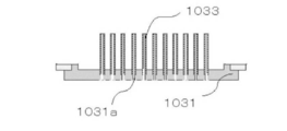
図2は、本発明の実施の形態におけるシャワープレート113を示す断面図である。第一構成部材1031、および、第二構成部材1032によって、水冷供給部111が構成されている。ガス吐出パイプ1033は、第一構成部材1031および第二構成部材1032に差し込まれている。シャワープレート113の製造方法を以下に説明する。各々の部品の材質は、たとえばステンレス(SUS316)製である。第一構成部材1031および第二構成部材1032の各々のサイズおよび孔数については、外径φが800mmであり、板厚みが10mmであり、貫通孔数が5000個である。ガス吐出パイプ1033は、円柱状のパイプであり、そのサイズおよび孔数については、外径がφ7mmであり、内径がφ5mmであり、個数は貫通孔数と同数の5000個である。これらのサイズは、54枚の基板(2インチ基板)に対応できる範囲である。これらのサイズは、基板のサイズまたは基板の搭載枚数に応じて変更可能であり、上記の値に限定されない。
図3A~図3Dは、それぞれ、シャワープレート113の製造方法の第1工程~第4工程を示す図である。図3Aに示すように、第一構成部材1031に、ガス吐出パイプ1033を設置するための貫通孔1031aが開けられる。貫通孔1031aは、ザグリ段差部分1031b(図4A参照)を有する。貫通孔1031aの開け方としては、貫通孔1031aを開ける際にザグリ段差部分1031bを同時に形成することができる専用の刃物が用いられるとよい。第一構成部材1031の水平面に対して垂直な方向にドリルを用いて貫通部を開け、その後、その貫通部を中心とするフライス加工を実施してザグリ段差部分1031bを設け、貫通孔1031aを形成するという方法が用いられてもよい。先にザグリ段差部分1031bを開け、その後、ザグリ段差部分1031bの中心に貫通部を開けて、貫通孔1031aを形成するという方法が用いられてもよい。
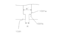
図4Aは、第一構成部材1031の貫通孔1031aを示す断面図である。図4Bは、第一構成部材1031の貫通孔1031aのザグリ段差部分1031bの上にガス吐出パイプ1033が配置された状態を示す断面図である。図4Aにおいて、直径Rは、第一構成部材1031の下面(原料ガスが吐出する面)側における貫通孔1031aの直径の値である。直径R´は、第一構成部材1031の他面(上面)側における貫通孔1031aの直径の値である。図4Bにおいて、外径rは、ガス吐出パイプ1033の外径の値である。貫通孔1031aは、直径Rが、直径R´および外径rよりも小さく、且つ、直径R´が外径rよりも大きくなるように、第一構成部材1031に開けられる。すなわち、貫通孔1031aは、以下に示す数式(1)の関係を満たすように、第一構成部材1031に開けられる。
R<r<R´・・・(1)
直径Rと直径R´との差によって、ザグリ段差部分1031bが形成される。ザグリ段差部分1031bの上にガス吐出パイプ1033の下面が載置されるように、ガス吐出パイプ1033は貫通孔1031aの中に差し込まれる。ガス吐出パイプ1033は、第一構成部材1031の下面から飛び出さない。ガス吐出パイプ1033の下面近傍とザグリ段差部分1031bとの間の溶接箇所は、第一構成部材1031の下面に出ることはほとんど無い。第一構成部材1031の下面を旋盤等で二次加工する際の削りシロは、大きく確保されることができる。貫通孔1031aの深さ(ザグリ段差部分1031bの位置)などについては、ガス吐出パイプ1033の大きさ、および、基板の加工条件などにより、最適化されるとよい。
直径Rと直径R´との差によって、ザグリ段差部分1031bが形成される。ザグリ段差部分1031bの上にガス吐出パイプ1033の下面が載置されるように、ガス吐出パイプ1033は貫通孔1031aの中に差し込まれる。ガス吐出パイプ1033は、第一構成部材1031の下面から飛び出さない。ガス吐出パイプ1033の下面近傍とザグリ段差部分1031bとの間の溶接箇所は、第一構成部材1031の下面に出ることはほとんど無い。第一構成部材1031の下面を旋盤等で二次加工する際の削りシロは、大きく確保されることができる。貫通孔1031aの深さ(ザグリ段差部分1031bの位置)などについては、ガス吐出パイプ1033の大きさ、および、基板の加工条件などにより、最適化されるとよい。
図3Bに示す状態では、第一構成部材1031に必要数の貫通孔1031aが開けられており、複数の貫通孔1031aの各々に、ガス吐出パイプ1033が1本ずつ差し込まれている。この状態で、ザグリ段差部分1031bの近傍とガス吐出パイプ1033の下面近傍とが溶接される。溶接においては、リークが発生しないように、ザグリ段差部分1031bの近傍とガス吐出パイプ1033の下面近傍との間の部分の全周が溶接される。ザグリ段差部分1031bを有する貫通孔1031aが第一構成部材1031に設けられていることで、第一構成部材1031のザグリ段差部分1031bの近傍も融解する。ザグリ段差部分1031bの近傍は、溶接部補完材として機能するため、溶接棒の代わりとなる。溶接対象個所の表面に凸凹が形成されることはなく、ザグリ段差部分1031bの近傍とガス吐出パイプ1033の下面近傍との間の部分を適切に溶接することが可能となる。貫通孔1031aにガス吐出パイプ1033が差し込まれた際に、ガス吐出パイプ1033の下面側の部分はザグリ段差部分1031bの近傍に確実に収められ、高さ方向の寸法を揃えることが可能となる。ザグリ段差部分1031bの近傍とガス吐出パイプ1033の下面近傍との間の部分は、安定した状態で容易に溶接されることが可能となる。この段階で溶接が完了した状態は、第一構成部材1031とガス吐出パイプ1033とが仮に固定されており、いわゆる仮止めの状態が形成されている。後述する本溶接が実施されることによって、第一構成部材1031とガス吐出パイプ1033とは、ピンホール等がない状態で溶接され、リークの発生は完全に防止される。
次に、第一構成部材1031の製造方法と同様の方法を用いて、第二構成部材1032が加工される。第二構成部材1032には、ガス吐出パイプ1033を通すための貫通孔1032aが開けられる。貫通孔1032aが第二構成部材1032に開けられる本数は、ガス吐出パイプ1033の本数と同じである。貫通孔1032aは、ザグリ段差部分1032b(図5参照)を有する。ザグリ段差部分1032bは、略円形の形状を有し、ガス吐出パイプ1033の出口部分においてガス吐出パイプ1033の外周を囲むように設けられる。
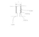
図5は、第二構成部材1032の貫通孔1032aを示す断面図である。貫通孔1032aにおいて、第二構成部材1032の下面側における貫通孔1032aの直径R´は、第一構成部材1031の貫通孔1031aにおける直径R´(図4A参照)と略等しい。第二構成部材1032の下面側における貫通孔1032aの直径R´は、ガス吐出パイプ1033の外径r(図4B参照)より大きく、かつ、ザグリ段差部分1032bの外径R´´よりも小さい。すなわち、貫通孔1032aは、以下に示す数式(2)の関係を満たすように、第二構成部材1032に開けられる。第一構成部材1031における直径R´の大きさおよび第二構成部材1032における直径R´の大きさについて、穴あけ加工時の誤差は、ここでは考慮しないこととする。ザグリ段差部分1032bの外径R´´、および、ザグリ段差部分1032bの深さ(ザグリ段差部分1032bが設けられる位置)は、差し込まれるガス吐出パイプ1033の厚み等の条件により、適宜設定される。
r<R´<R´´・・・(2)
次に、図3Cに示すように、第一構成部材1031の上方から第一構成部材1031に対して蓋をするように、第二構成部材1032が第一構成部材1031に取り付けられる。ガス吐出パイプ1033は、第二構成部材1032の貫通孔1032aに差し込まれる。第一構成部材1031と第二構成部材1032とは、ねじ止めされる。第一構成部材1031、および、第二構成部材1032によって、水冷供給部111が構成される。水冷供給部111に冷却水を通すことにより、シャワープレート近傍での原料ガスの反応が抑えられる。
次に、図3Cに示すように、第一構成部材1031の上方から第一構成部材1031に対して蓋をするように、第二構成部材1032が第一構成部材1031に取り付けられる。ガス吐出パイプ1033は、第二構成部材1032の貫通孔1032aに差し込まれる。第一構成部材1031と第二構成部材1032とは、ねじ止めされる。第一構成部材1031、および、第二構成部材1032によって、水冷供給部111が構成される。水冷供給部111に冷却水を通すことにより、シャワープレート近傍での原料ガスの反応が抑えられる。
本実施の形態の図3Cに示す状態では、ガス吐出パイプ1033は、第二構成部材1032上面から1.5mmの長さ分だけ突き出している。ガス吐出パイプ1033のうちの突き出た部分とザグリ段差部分1032bの近傍との間の部分は、溶接される。ガス吐出パイプ1033のうちの長く突き出た部分は、溶けて、ザグリ段差部分1032bへと流れ込む。ガス吐出パイプ1033のうちの長く突き出た部分は、溶接部補完材として働く。結果として、肉盛を生じることなく、平面を形成することができる。図3Cにおいて、黒い丸で示された部分が、全て溶接される。溶接の手順としては、第一構成部材1031の下面の貫通孔1031aの周辺の溶接と、第二構成部材1032の上面からの貫通孔1032aの周辺の本溶接とが、交互に実施されるとよい。望ましくは、第一構成部材1031の下面の貫通孔1031aの周辺の溶接と、第二構成部材1032の上面からの貫通孔1032aの周辺の本溶接とが、互いに離れた部分から順に実施される。当該構成によれば、第一構成部材1031および第二構成部材1032に歪みが生じることを、極力抑えることが可能となる。溶接に用いられる材料、あるいは、溶接の際の状況などにより、溶接のための最適な条件は変化する。したがって、溶接対象箇所に対する溶接実施の順番、溶接のスピード、および、溶接に用いられる電圧に関しては、特に限定されない。溶接対象箇所に対する溶接実施の順番などは、使用される材料および材質などに応じて、適宜変化させるとよい。本実施の形態の溶接構造においては、第一構成部材1031および第二構成部材1032はそれぞれ異なる形状を有しているが、これらは双方とも同じ形状を有するように製造されてもよい。
反りの発生に関して、第一構成部材1031、第二構成部材1032、および、ガス吐出パイプ1033は、溶接時に融解するため、これらに熱が発生することは避けられない。熱の発生に起因する反りの発生を抑制するために、たとえば図6に示すような、固定部材114が用いられるとよい。溶接の開始前に、固定部材114を用いて、第一構成部材1031、第二構成部材1032、および、ガス吐出パイプ1033が組み立てられる。第一構成部材1031の外周部分および第二構成部材1032の外周部分は、固定部材114によって挟み込まれる。この状態で、溶接が実施される。固定部材114は、たとえばドーナツ形状を有している。固定部材114は、第一構成部材1031および第二構成部材1032に発生する反りに負けない強度を有する。固定部材114は、少なくとも第一構成部材1031および第二構成部材1032を合わせた以上の厚みを有していることが望ましい。固定部材114を用いることにより、シャワープレート113は、まったく反ることがなくなり、安定した溶接を実施することが可能となる。
全てのガス吐出パイプ1033の周辺に対する溶接が完了し、溶接箇所が固定された後、固定部材114が第一構成部材1031および第二構成部材1032から離脱される。その後、第一構成部材1031および第二構成部材1032同士の接合部分に、溶接が実施される。
最後に、図3Dに示すように、第一構成部材1031から第二構成部材1032にかけて、あるいは、第二構成部材1032から第一構成部材1031にかけて、ドリル等を用いた切削が行われる。溶接のときにガス吐出パイプ1033の周囲および内部に付着した余分な材料は、ドリル加工などによって削り落とされる。さらに、第一構成部材1031の表面は、旋盤あるいは平面研削盤等を用いて、平坦化される。
第二構成部材1032の上面においては、ガス吐出パイプ1033のうちの突き出た部分が削られる。第二構成部材1032の上面は、平坦になるまで削られる。この際、削り取られるべき範囲としては、溶接箇所が削り取られない程度にとどめられる。第一構成部材1031の下面は、付着した溶接材料を除去する程度に削られる。この際も、削り取られるべき範囲としては、溶接箇所が削り取られない程度にとどめられる。第一構成部材1031の下面は、第一構成部材1031および第二構成部材1032をあわせた厚みが、所望の厚みになるまで削られる。貫通孔を設けることにより、溶接による肉盛が抑えられ、シャワープレート113のガス吐出面を容易に平坦化することが可能となる。
以上説明した手順により、シャワープレート113が作成される。このシャワープレート113を用いたMOCVD装置によれば、装置が大型化したりガス吐出孔の配置ピッチが細かくなったりすることに起因して孔数が増加したとしても、シャワーヘッド103に反りおよび歪みが発生すること、ならびに、シャワーヘッド表面に凹凸が発生することを抑制することができる。結果として、このMOCVD装置によれば、均一な膜厚および均一な組成比を有する良質な半導体デバイスを製造することが可能となる。第一構成部材1031および第二構成部材1032によって形成された水冷供給部111により、原料ガスを冷却し、余分な生成物の付着を防止することも可能となる。
<比較例>
本発明に基づく実施の形態の効果を実証するために、以下のような比較実験を行った。
本発明に基づく実施の形態の効果を実証するために、以下のような比較実験を行った。
図7は、従来の方法で作成されたシャワープレート513の断面図である。シャワープレート513においては、第一構成部材5031および第二構成部材5032によって、水冷供給部511が構成される。ガス吐出パイプ5033は、第一構成部材5031および第二構成部材5032に差し込まれている。シャワープレート513の製造方法を以下に説明する。
上記の実施の形態で用いたものと同じ基板および同じガス吐出パイプを用意し、貫通孔の数は、上記の実施の形態と同様に5000個である。第一構成部材5031には、ガス吐出パイプ5033を差込むための貫通孔が開けられており、その貫通孔にガス吐出パイプ5033が差し込まれている。必要数の差込が終わると、第一構成部材5031の貫通孔の内周部分とガス吐出パイプ5033の外周部分との間の部分が仮溶接される。水冷供給部511の下側の部分が構成される。この時、溶接においては、リークが発生しないように、上記実施の形態と同様に、全箇所に対して全周溶接が実施される。次に、第一構成部材5031に対して第二構成部材5032が蓋をするように、第二構成部材5032が第一構成部材5031に取り付けられる。第二構成部材5032には、第一構成部材5031と同様に、ガス吐出パイプ5033の外径よりも少し大きい貫通孔が開けられている。その貫通孔に、第一構成部材5031に溶接されているガス吐出パイプ5033が差し込まれる。差し込みが完了すると、第一構成部材5031の内周部分およびガス吐出パイプ5033の外周部分、ならびに、第二構成部材5032の内周部分およびガス吐出パイプ5033の外周部分に対して、全周溶接が実施される。図7における黒い丸は、溶接箇所を示している。第一構成部材5031とガス吐出パイプ5033との間の5000箇所、ならびに、第二構成部材5032とガス吐出パイプ5033との間の5000箇所、合わせて10000箇所の溶接が実施される。第一構成部材5031および第二構成部材5032とガス吐出パイプ5033とを溶接した際に材料自体が融解することにより発生する凹み部分については、各々の材料を溶接した後に、凹み部分に各材料と同じSUS316よりなる溶接棒が差し込まれる。溶接棒が融解され、凹み部分の解消が行われる。最後に、第一構成部材5031の外周全体と第二構成部材5032の外周全体とが溶接され、水冷供給部511が構成される。
図8Aは、上記の方法にて作成されたシャワープレート513を示す平面図である。図8Bは、図8A中におけるVIIIB-VIIIB線に沿った矢視断面図である。図8Cは、図8A中におけるVIIIC-VIIIC線に沿った矢視断面図である。反りおよび歪みに関して、中心部分と外周部分との高さの差t(図8Bおよび図8C参照)を測定したところ、差tの値はおよそ12mm程度であった。肉眼で見ても、かなりの大きさを有する反りが形成された。反りの方向に関しては、シャワープレート513の中心部部分が凹み、シャワープレート513の全体が椀状に反ってしまい、中心部分にもっとも大きい反り形状が形成された。
溶接棒を入れる前の状態での融解による凹み部分は、およそ2mmとなった。許容される反りの値は、反応ガスの流速およびシュミレーション結果(図示せず)から、0.1mm以下であることが望ましい。今回の結果から判断すると、シャワープレート513は、使用に耐え難いものであることが分かる。凹み部分に溶接棒を挿した状態で溶接した部分については、必要な平面に対して、2mm以上の凸形状を有する盛り上がり(肉盛)が形成された。凹み部分に溶接棒を挿した状態で溶接した部分についても、反りを補正した後に、肉盛部分を2次加工により除去しなければならない状態となった。
次に、上記の12mm程度の反りを補正するために、反りと反対方向からシャワープレート513に対して300トン以上の力を付与してシャワープレート513を塑性変形させ、反りの補正を行った。12mmの反りを補正するときは、反りの反対方向に沿って、26mm以上のプレスをシャワープレート513に対して複数箇所行なった。26mm以上のプレスは、材料の塑性領域を超える値である。このプレスの実施によって、12mmの反りを解消することに成功した。しかしながら、ヘリウムを用いた減圧透過検査によりリークの有無を調べたところ、3000箇所程度からリークが発見された。シャワープレート513の表面を観察すると、溶接箇所に亀裂が発生している箇所も発見された。第一構成部材5031および第二構成部材5032の溶接箇所以外の箇所についても、亀裂が発生している箇所が発見された。この理由は、反りを補正するために、300トン以上の力をシャワープレート513に付与し、シャワープレート513を26mm以上塑性変形をさせたことにより、発生したものと考えられる。上述の肉盛部分についても、2次加工し除去を実施したが、凸部分が2mm以上あるため、除去加工が非常に困難なものであり、除去しきれない部分も発生していた。
上記の結果を分析すると、反りの発生の原因は、第一構成部材5031および第二構成部材5032とガス吐出パイプ5033との溶接時の熱というよりむしろ、溶接後の凹みを解消するために溶接棒を再度融解し、より多くの熱を入れたことに起因していることが判明した。溶接箇所、第一構成部材5031および第二構成部材5032に発生した割れについては、シャワープレート513を塑性変形させ、シャワープレート513の反りを補正したことにより生じたということも判明した。溶接箇所においては、融解範囲(熱が影響を与える部分)が想定以上に大きく、シャワーヘッドの表面が凸凹になるという結果が得られた。
これらの結果より、シャワーヘッドの水冷供給部を構成する第一構成部材および第二構成部材とガス吐出パイプとの溶接において、第一構成部材および第二構成部材にザグリ段差部分を有する貫通孔を設けることにより、シャワープレートの反りおよび歪みを抑えることができ、肉盛による表面の凹凸を少なくすることができることがわかる。第一構成部材および第二構成部材によって構成された水冷供給部により、シャワーヘッド内部で原料ガスが高温になり反応するのを抑制することができる。よって、このシャワープレートをMOCVD装置に用いることで、装置の大型化にも対応でき、均一な膜厚および均一な組成比を有する良質な半導体デバイスを製造することが可能となることがわかる。
本発明は、シャワーヘッド上部の空間にガスを導入し、シャワープレートに設けられた複数のガス吐出孔より被処理基板の表面に反応ガスを供給するシャワーヘッドを用いた縦型のMOCVD装置に好適に利用できる。
100,600,800 MOCVD装置(気相成長装置)、101,611 成長室、102,601 反応炉、103 シャワーヘッド、104,612 回転軸、105 ヒータカバー、106 支持台、107,609,808 ヒータ、108,608 サセプタ、109a 第1ガス分配空間、109b 第1ガス配管、109c 第1ガス流路、110a 第2ガス分配空間、110b 第2ガス配管、110c 第2ガス流路、111,511 水冷供給部(冷却用空洞部)、112,604 ガス排気部、113,513,610,701,813 シャワープレート、114 固定部材、602 ガス供給源、603 ガス配管、605 パージライン、606 排ガス処理装置、607,704,806 基板、700 気相成長装置、702 冷却チャンバ、703 側壁、801 成長チャンバ、802 第1ガス供給コネクタ、803 第2ガス供給コネクタ、804 キャリアガス供給コネクタ、805 ドーパントガス供給コネクタ、807 保持台、809 ガス冷却部、810 冷却ジャケット、811 排気口、812 ガス通路、1031,5031 第一構成部材、1031a,1032a 貫通孔、1031b,1032b ザグリ段差部分、1032,5032 第二構成部材、1033,5033 ガス吐出パイプ。
Claims (7)
- 気相成長装置(100)に用いられるシャワープレート(113)の製造方法であって、
第一構成部材(1031)および第二構成部材(1032)のそれぞれに、ザグリ段差部分(1031b,1032b)を有する貫通孔(1031a,1032a)を設ける工程と、
前記第一構成部材の前記ザグリ段差部分(1031b)にガス吐出パイプ(1033)の一端を差し込む工程と、
前記第一構成部材の前記ザグリ段差部分(1031b)に差し込まれた前記ガス吐出パイプの他端が前記第二構成部材から突出するように、前記第二構成部材に設けられた前記貫通孔(1032a)に前記ガス吐出パイプを差し込む工程と、
前記第一構成部材の前記ザグリ段差部分(1031b)および前記ガス吐出パイプ(1033)同士を溶接する第一溶接工程と、
前記第二構成部材の前記ザグリ段差部分(1032b)および前記ガス吐出パイプ(1033)同士を溶接する第二溶接工程と、
前記第一構成部材(1031)および前記第二構成部材(1032)同士を溶接する工程と、を備える、
シャワープレートの製造方法。 - 前記シャワープレート(113)は、冷却用空洞部(111)を有する、
請求項1に記載のシャワープレートの製造方法。 - 前記第一構成部材(1031)、前記第二構成部材(1032)、および、前記ガス吐出パイプ(1033)は、同一の材料よりなる、
請求項1に記載のシャワープレートの製造方法。 - 前記第一溶接工程およびまたは前記第二溶接工程において、溶接された部分が前記第一構成部材(1031)および前記第二構成部材(1032)の表面に突出しないように溶接される、
請求項1に記載のシャワープレートの製造方法。 - 前記第一溶接工程およびまたは前記第二溶接工程において、前記第一構成部材(1031)および前記第二構成部材(1032)が互いに固定された状態で溶接が行われる、
請求項1に記載のシャワープレートの製造方法。 - 請求項1に記載のシャワープレートの製造方法を用いて製造される、
シャワープレート。 - 請求項6に記載のシャワープレートを用いる、
気相成長装置。
Applications Claiming Priority (2)
| Application Number | Priority Date | Filing Date | Title |
|---|---|---|---|
| JP2011-129131 | 2011-06-09 | ||
| JP2011129131A JP5095843B1 (ja) | 2011-06-09 | 2011-06-09 | シャワープレートの製造方法、シャワープレート及びこれを用いた気相成長装置 |
Publications (1)
| Publication Number | Publication Date |
|---|---|
| WO2012169332A1 true WO2012169332A1 (ja) | 2012-12-13 |
Family
ID=47295901
Family Applications (1)
| Application Number | Title | Priority Date | Filing Date |
|---|---|---|---|
| PCT/JP2012/062755 Ceased WO2012169332A1 (ja) | 2011-06-09 | 2012-05-18 | シャワープレートの製造方法、シャワープレートおよびこれを用いた気相成長装置 |
Country Status (3)
| Country | Link |
|---|---|
| JP (1) | JP5095843B1 (ja) |
| TW (1) | TW201305382A (ja) |
| WO (1) | WO2012169332A1 (ja) |
Families Citing this family (6)
| Publication number | Priority date | Publication date | Assignee | Title |
|---|---|---|---|---|
| JP6626800B2 (ja) * | 2016-08-19 | 2019-12-25 | 東京エレクトロン株式会社 | プラズマ処理装置のシャワープレートを検査する方法 |
| JP6700156B2 (ja) * | 2016-11-16 | 2020-05-27 | 株式会社ニューフレアテクノロジー | 成膜装置 |
| JP6789774B2 (ja) * | 2016-11-16 | 2020-11-25 | 株式会社ニューフレアテクノロジー | 成膜装置 |
| CN107699864B (zh) * | 2017-09-14 | 2019-08-20 | 中山大学 | Mocvd设备进气装置和反应腔的结构及该设备的薄膜生长方法 |
| KR20200045785A (ko) * | 2018-10-23 | 2020-05-06 | 안범모 | 반도체 제조 공정용 또는 디스플레이 제조 공정용 프로세스 유체가 통과하는 접합부품 |
| CN117403210B (zh) * | 2023-11-02 | 2025-12-05 | 希科半导体科技(苏州)有限公司 | 一种外延炉喷淋装置 |
Citations (3)
| Publication number | Priority date | Publication date | Assignee | Title |
|---|---|---|---|---|
| JPH08337876A (ja) * | 1995-06-09 | 1996-12-24 | Ebara Corp | 反応ガス噴射ヘッド及び薄膜気相成長装置 |
| JP2002097576A (ja) * | 2000-09-21 | 2002-04-02 | Ebara Corp | ガス噴射ヘッド及びcvd装置 |
| JP2010062383A (ja) * | 2008-09-04 | 2010-03-18 | Sharp Corp | 気相成長装置及び気相成長方法 |
-
2011
- 2011-06-09 JP JP2011129131A patent/JP5095843B1/ja not_active Expired - Fee Related
-
2012
- 2012-05-18 WO PCT/JP2012/062755 patent/WO2012169332A1/ja not_active Ceased
- 2012-06-06 TW TW101120354A patent/TW201305382A/zh unknown
Patent Citations (3)
| Publication number | Priority date | Publication date | Assignee | Title |
|---|---|---|---|---|
| JPH08337876A (ja) * | 1995-06-09 | 1996-12-24 | Ebara Corp | 反応ガス噴射ヘッド及び薄膜気相成長装置 |
| JP2002097576A (ja) * | 2000-09-21 | 2002-04-02 | Ebara Corp | ガス噴射ヘッド及びcvd装置 |
| JP2010062383A (ja) * | 2008-09-04 | 2010-03-18 | Sharp Corp | 気相成長装置及び気相成長方法 |
Also Published As
| Publication number | Publication date |
|---|---|
| JP2012256730A (ja) | 2012-12-27 |
| JP5095843B1 (ja) | 2012-12-12 |
| TW201305382A (zh) | 2013-02-01 |
Similar Documents
| Publication | Publication Date | Title |
|---|---|---|
| JP5026373B2 (ja) | 気相成長装置及び気相成長方法 | |
| WO2012169332A1 (ja) | シャワープレートの製造方法、シャワープレートおよびこれを用いた気相成長装置 | |
| JP4576466B2 (ja) | 気相成長装置及び気相成長方法 | |
| US20070266932A1 (en) | Vapor phase growth apparatus and method for vapor phase growth | |
| JP4699545B2 (ja) | 気相成長装置及び気相成長方法 | |
| JP2009088088A (ja) | 基板処理装置および基板処理方法 | |
| JP5125095B2 (ja) | SiCエピタキシャル膜付き基板の製造方法及びSiCエピタキシャル膜付き基板の製造装置 | |
| US7060944B2 (en) | Heat treatment device and heat treatment method | |
| JP2009164570A (ja) | 気相処理装置、気相処理方法および基板 | |
| US20140224176A1 (en) | Mocvd apparatus | |
| WO2012132575A1 (ja) | シャワープレート、気相成長装置及び気相成長方法 | |
| WO2012172920A1 (ja) | 基板支持装置及び気相成長装置 | |
| JP2010238831A (ja) | 気相成長装置及び気相成長方法 | |
| KR20140018148A (ko) | 화합물 반도체막의 성막 방법 및 성막 장치 | |
| JP5031910B2 (ja) | 気相成長装置 | |
| JP5259804B2 (ja) | 気相成長装置及び気相成長方法 | |
| JP2009249651A (ja) | 気相成長装置及び気相成長方法 | |
| KR102806978B1 (ko) | 채널이 형성된 탄화규소 플레이트 및 그 제조방법 | |
| JP2010245135A (ja) | 気相成長装置 | |
| JP6861490B2 (ja) | 窒化物結晶基板の製造方法および結晶成長用基板 | |
| JP2014207357A (ja) | サセプタ及びそれを用いた気相成長装置 | |
| JP4879693B2 (ja) | Mocvd装置およびmocvd法 | |
| JP5184410B2 (ja) | カバープレートユニット、及びそれを備えた気相成長装置 | |
| KR102843688B1 (ko) | 채널이 형성된 탄화규소 플레이트 및 그 제조방법 | |
| JP2013105831A (ja) | 気相成長装置 |
Legal Events
| Date | Code | Title | Description |
|---|---|---|---|
| 121 | Ep: the epo has been informed by wipo that ep was designated in this application |
Ref document number: 12796090 Country of ref document: EP Kind code of ref document: A1 |
|
| NENP | Non-entry into the national phase |
Ref country code: DE |
|
| 122 | Ep: pct application non-entry in european phase |
Ref document number: 12796090 Country of ref document: EP Kind code of ref document: A1 |