WO2012165579A1 - プラスチックレンズ - Google Patents
プラスチックレンズ Download PDFInfo
- Publication number
- WO2012165579A1 WO2012165579A1 PCT/JP2012/064167 JP2012064167W WO2012165579A1 WO 2012165579 A1 WO2012165579 A1 WO 2012165579A1 JP 2012064167 W JP2012064167 W JP 2012064167W WO 2012165579 A1 WO2012165579 A1 WO 2012165579A1
- Authority
- WO
- WIPO (PCT)
- Prior art keywords
- film
- photochromic
- plastic substrate
- plastic
- plastic lens
- Prior art date
Links
Images


Classifications
-
- G—PHYSICS
- G02—OPTICS
- G02C—SPECTACLES; SUNGLASSES OR GOGGLES INSOFAR AS THEY HAVE THE SAME FEATURES AS SPECTACLES; CONTACT LENSES
- G02C7/00—Optical parts
- G02C7/10—Filters, e.g. for facilitating adaptation of the eyes to the dark; Sunglasses
- G02C7/102—Photochromic filters
-
- G—PHYSICS
- G02—OPTICS
- G02B—OPTICAL ELEMENTS, SYSTEMS OR APPARATUS
- G02B1/00—Optical elements characterised by the material of which they are made; Optical coatings for optical elements
- G02B1/10—Optical coatings produced by application to, or surface treatment of, optical elements
-
- G—PHYSICS
- G02—OPTICS
- G02B—OPTICAL ELEMENTS, SYSTEMS OR APPARATUS
- G02B1/00—Optical elements characterised by the material of which they are made; Optical coatings for optical elements
- G02B1/10—Optical coatings produced by application to, or surface treatment of, optical elements
- G02B1/14—Protective coatings, e.g. hard coatings
-
- G—PHYSICS
- G02—OPTICS
- G02B—OPTICAL ELEMENTS, SYSTEMS OR APPARATUS
- G02B5/00—Optical elements other than lenses
- G02B5/20—Filters
- G02B5/22—Absorbing filters
- G02B5/23—Photochromic filters
-
- G—PHYSICS
- G02—OPTICS
- G02C—SPECTACLES; SUNGLASSES OR GOGGLES INSOFAR AS THEY HAVE THE SAME FEATURES AS SPECTACLES; CONTACT LENSES
- G02C7/00—Optical parts
- G02C7/02—Lenses; Lens systems ; Methods of designing lenses
Definitions
- the present invention relates to a plastic lens for spectacles and the like.
- the present invention relates to a photochromic lens in which a photochromic film is formed on a lens substrate.
- plastic photochromic lenses also referred to as light control lenses
- organic photochromic dyes are commercially available for eyeglasses. These have the same antiglare effect as a high-density color lens by coloring in a bright outdoors, and recover high transmittance when moving indoors.
- This photochromic function is imparted by forming a film made of a composition containing a photochromic dye on the lens surface. In forming such a photochromic film, it is required to ensure adhesion with the lens substrate and film strength.
- Patent Document 1 it is said that the adhesion to the optical substrate and the film strength can be improved by forming a photochromic film with a composition having a specific component and blending ratio.
- a photochromic film is formed on the convex surface of the lens, and the optimum film thickness is 10 ⁇ m to 50 ⁇ m.
- the photochromic film is conventionally provided on the convex surface of the lens. This is because most lens substrates contain an ultraviolet absorber to protect the eyes of the user. Specifically, an ultraviolet absorber that absorbs ultraviolet light having a wavelength shorter than 400 nm is included.
- the photochromic film exhibits a dimming effect when irradiated with ultraviolet rays. Therefore, if a photochromic film is provided on the back surface (usually concave) of the lens, the ultraviolet light is absorbed by the ultraviolet absorber in the lens substrate, and sufficient ultraviolet light does not reach the photochromic film, making it difficult to obtain a desired dimming action.
- a photochromic film 12 is formed on the convex surface side of the plastic substrate 11, and a hard coat layer 14 is provided on the photochromic film 12.
- a hard coat layer 15 is also provided on the concave surface of the plastic substrate 11.
- a plastic lens having a refractive index of 1.60 or more is thinner than a lens having a low refractive index, and thus the above phenomenon is likely to occur.
- it is necessary to lower the curing temperature of the hard coat layer.
- the hard coat layer is formed at a low temperature, sufficient impact resistance (film hardness) and film adhesion are ensured. It was difficult.
- an object of the present invention is to provide a plastic lens that can suppress deformation while having a photochromic film.
- a plastic lens according to the present invention includes a meniscus-shaped plastic substrate having a concave surface and a convex surface, and a photochromic film provided on the convex surface of the plastic substrate. Moreover, it has the stress correction film
- the stress caused by the shrinkage of the photochromic film provided on the convex surface of the plastic substrate can be canceled by the stress caused by the shrinkage of the stress correction film provided on the concave surface of the plastic substrate.
- this stress correction film may contain a photochromic dye. That is, the stress correction film can be used as a photochromic film provided on the concave surface of the plastic substrate. As a result, the color density of the entire plastic lens can be improved. Further, even if the photochromic film provided on the convex surface of the plastic substrate is damaged, color development can be maintained by the stress correction film.
- the stress applied to the plastic substrate by the photochromic film provided on the concave surface of the plastic substrate can be canceled. For this reason, it is possible to provide a high-quality plastic lens in which deformation is suppressed.
- FIG. 1 is a schematic configuration diagram showing an example of a cross-sectional configuration of a plastic lens 100 according to an embodiment of the present invention.
- the outline of a structure is shown and it does not limit the dimensional ratio etc. of each site
- the plastic lens 100 according to the present embodiment has, for example, a meniscus lens shape having a convex surface on one surface and a concave surface on the other surface.
- the plastic lens 100 of the present embodiment includes a plastic substrate 1 having a convex surface on one surface and a concave surface on the other surface, a photochromic film 2 formed on the convex surface of the plastic substrate 1, and a photochromic film 2
- the hard coat layer 4 is formed.
- An antireflection film 6 is formed on the hard coat layer 4.
- the plastic lens 100 includes a stress correction film 3 provided on the concave surface of the plastic substrate 1 and a hard coat layer 5 formed on the stress correction film 3.
- the antireflection film 6 is not necessarily formed, and other films having other additional functions may be provided.
- the material of the plastic substrate 1 is not particularly limited.
- the hard coat layers 4 and 5 and the antireflection film 6 are not particularly limited. Moreover, you may interpose the primer layer which is not illustrated between the plastic substrate 1 mentioned above, each film
- the material of the stress correction film 3 may be the same as that of the photochromic film 2, but the photochromic dye need not necessarily be contained. However, at least a curable component that is cured by a polymerization reaction and a polymerization initiator that promotes polymerization of the curable component are included. Further, hard coat layers 4 and 5 are laminated on the photochromic film 2 and the stress correction film 3, for example, as shown in FIG. If the hard coat layers 4 and 5 have a thickness of, for example, about 1 ⁇ m to 3 ⁇ m, they can function as protective layers for the photochromic film 2 and the stress correction film 3. Further, a primer layer (not shown) may be interposed between the plastic substrate 1 and the stress correction film 3 in order to improve the adhesion between the plastic substrate 1 and the stress correction film 3.
- the plastic lens 100 has the stress correction film 3 provided on the concave surface of the plastic substrate 1.
- the stress correction film 3 contains a curable component of a photochromic film and a polymerization initiator, for example, when the hard coat layers 4 and 5 are thermally cured, the stress correction film 3 is a photochromic film. Similar to 2, heat shrinkage occurs. For this reason, the stress applied to the plastic substrate 11 by the thermal contraction of the photochromic film 2 provided on the convex surface can be canceled by the stress generated by the thermal contraction of the stress correction film 3 provided on the concave surface. Therefore, deformation of the lens can be suppressed, and a high-quality plastic lens can be provided.
- the stress correction film 3 may contain a photochromic dye.
- a photochromic film is formed on both the convex surface and the concave surface of the plastic substrate 1.
- ultraviolet rays that are not absorbed by the photochromic film 2 can be absorbed by the photochromic film (stress correction film 3) on the concave surface side.
- stress correction film 3 by developing the color of the stress correction film 3, it is possible to increase the utilization efficiency of ultraviolet rays incident on the plastic lens 100 and to improve the color density of the plastic lens 100.
- the light transmittance with respect to the plastic lens 100 is about 12 ⁇ 1% in a temperature environment of 23 ° C. in a gray tone.
- the photochromic film is provided on both surfaces of the plastic substrate 1, the photochromic layer on the concave side is also colored by the ultraviolet rays incident on the concave side, and the transmittance is about 9 ⁇ 1% and the color density is increased.
- the stress correction film 3 as a photochromic film, even if the photochromic film 2 is damaged, the color correction performance can be maintained by the stress correction film 3.
- the material of the plastic substrate 1 used for the plastic lens of the present invention is not particularly limited.
- the surface shape of the substrate was convex or flat on the objective side (surface opposite to the eye for spectacles) and concave on the other side (eye side surface for spectacles).
- the so-called meniscus plastic substrate even if it is a biconvex shape or a biconcave shape, the effect of suppressing deformation can be obtained in the same manner.
- the plastic substrate 1 does not contain an ultraviolet absorber or is a material in which the content of the ultraviolet absorber is adjusted to be lower than usual. Alternatively, it is preferable to use a material that transmits ultraviolet light. Thereby, the ultraviolet rays not absorbed by the photochromic film 2 can reach the stress correction film 3.
- the plastic substrate 1 is preferably configured so that the accumulated transmittance in the wavelength range of at least 300 nm to 420 nm is 14% or more, and the accumulated transmittance in the wavelength range of 300 to 410 nm is more than 27%.
- the material of the plastic substrate 1 include diethylene glycol bisallyl carbonate (CR39 manufactured by PPG).
- Primer layer A primer layer may be appropriately formed between the plastic substrate 1, the photochromic films 2 and 3, the hard coat layers 4 and 5, the antireflection film 6 and the like as necessary.
- the material used for the primer layer is not particularly limited as long as it improves adhesion and impact resistance, and when the plastic substrate is made of a high refractive index material, it does not affect the optical properties.
- polyols, polyisocyanates, NCO group blocking agents of polyisocyanates, and materials containing metal oxides in addition to these can be used.
- polystyrene resin examples include polycarbonate polyol (for example, “Nipporan 980 series (trade name)” manufactured by Nippon Polyurethane Industry Co., Ltd., “carbodiol (trade name)” manufactured by Toagosei Co., Ltd.), and polyether polyol (for example, (stock) ) "ADEKA Polyether (trade name)” manufactured by ADEKA, “ACTCOL PPG-Diol series (trade name)” manufactured by Mitsui Chemicals Polyurethane Co., Ltd.), acrylic polyol (for example, "Takelac (registered trademark)” ) ", DIC (formerly Dainippon Ink and Chemicals, Inc.” Acridick (registered trademark) ", etc.), or polyester polyol (DIC Corporation” Polylite (registered trademark) ", Kuraray Co., Ltd.) Kuraray polyol series (trade name) ”) and the like can be used.
- polycarbonate polyol for example, “Nipporan 980
- polyisocyanates polyisocyanate hexamethylene diisocyanate, 1,3,3-trimethylhexamethylene diisocyanate, isophorone diisocyanate, 4,4'-dicyclohexylmethane diisocyanate, xylylene diisocyanate, tetramethylxylylene diisocyanate, hydrogenated xylylene diene
- Polyisocyanates such as isocyanate, tolylene diisocyanate, diphenylmethane diisocyanate, hydrogenated diphenylmethane diisocyanate, 1,5-naphthalene diisocyanate, tetramethylxylylene diisocyanate or their modified products, isocyanurates, allophanates, burettes or carbodiimides, or trimers thereof
- An adduct body such as a body can be used.
- NCO group blocking agent of polyisocyanate ⁇ -diketone and methyl ethyl ketoxime are preferable, but acetylacetone, 2,4-hexanedione, 3,5-heptanedione, acetoxime, methyl ethyl ketoxime, caprolactam, and the like can be used. .
- a metal oxide may be added to such a primer composition in order to increase the refractive index.
- the metal oxide include metal oxides composed of one or more metals selected from Si, Al, Sn, Sb, Ta, Ce, La, Fe, Zn, W, Zr, In, and Ti, and further, A sol made of metal oxide fine particles can be used.
- Solvents include ethylene glycol monomethyl ether acetate, ethylene glycol monoethyl ether acetate, ethylene glycol monopropyl ether acetate, ethylene glycol monobutyl ether acetate, propylene glycol monomethyl ether acetate, propylene glycol monoethyl ether acetate, propylene glycol monopropyl ether acetate, Propylene glycol monobutyl ether acetate, ethylene glycol dimethyl ether, ethylene glycol diethyl ether, ethylene glycol dipropyl ether, ethylene glycol dibutyl ether, diethylene glycol dimethyl ether, diethylene glycol diethyl ether, diethylene glycol dipropyl ether Ether, may be used diethylene glycol dibutyl ether, glycols such as propylene glycol dimethyl ether or propylene glycol diethyl ether.
- a copolymer of polyoxyalkylene and polydimethylsiloxane or a copolymer of polyoxyalkylene and fluorocarbon can be used.
- the photochromic film 2 is formed by applying and curing a coating liquid having a photochromic dye on the plastic substrate 1.
- a coating liquid can be comprised from a sclerosing
- the method for preparing the coating liquid is not particularly limited, and the coating liquid can be prepared by weighing and mixing a predetermined amount of each component.
- the viscosity of the coating liquid at 25 ° C. is preferably 20 to 500 cp, and more preferably 50 to 300 cp. Furthermore, it is particularly preferably 60 to 200 cp. By setting it as this viscosity range, application
- the curable component that can be used for forming the photochromic film is not particularly limited, and for example, a known curable component having a radical polymerizable group such as a (meth) acryloyl group, a (meth) acryloyloxy group, a vinyl group, an aryl group, or a styryl group. These photopolymerizable monomers and oligomers and their prepolymers can be used.
- (meth) acryloyl shows both acryloyl and methacryloyl.
- UV curing is applied after application, and in the case of a urethane material, a thermosetting treatment is performed to complete a film.
- the components described in JP-A-2008-33223, JP-A-2007-77327, and the like can be used.
- the photochromic dye compound is not particularly limited, and a known one may be used. Examples thereof include photochromic dye compounds such as fulgimide compounds, spirooxazine compounds, and chromene compounds.
- photochromic dye compounds such as fulgimide compounds, spirooxazine compounds, and chromene compounds.
- dye what expresses photoisomerization reaction in the short wavelength side of visible light is preferable.
- the specific wavelength is 420 nm or less, preferably 410 nm or less. Light of this wavelength is contained in a large amount in sunlight, but there are only a few in an indoor environment or an environment under normal lighting. Accordingly, the color development of the plastic lens of the present invention is suppressed indoors, but the color can be developed in an outdoor environment.
- additives include surfactants, antioxidants, radical scavengers, UV stabilizers, UV stabilizers to improve photochromic dye durability, color development speed, fading speed and moldability.
- additives known compounds can be used without any particular limitation.
- the stress correction film 3 includes a curable component that is cured by a polymerization reaction and a polymerization initiator that promotes the polymerization reaction of the curable component.
- a material that causes thermal shrinkage at the thermosetting temperature of the hard coat layers 4 and 5 is used as the curable component.
- the curable component and the polymerization initiator those similar to the curable component of the so-called photochromic film and the polymerization initiator can be used. Accordingly, the curable component of the photochromic film 2 and the material of the polymerization initiator may be appropriately selected and used. The curable component and the polymerization initiator of the photochromic film 2 and the stress correction film 3 may be exactly the same or different. Moreover, the stress correction film
- membrane 3 may contain the above-mentioned additive.
- the stress correction film 3 may contain a photochromic dye, or may be formed as a second photochromic film provided on the concave surface side of the plastic substrate 1.
- the photochromic dye is not particularly limited, and known ones can be used.
- the configuration of the stress correction film 3 may be the same as that of the photochromic film 2.
- hard coat layers 4 and 5 are provided as hard films, respectively.
- the material for the hard coat layers 4 and 5 is not particularly limited, and a coating liquid made of a known organosilicon compound and metal oxide colloidal particles can be used. After applying the coating liquid, a hard coat layer can be obtained by a curing treatment.
- the organosilicon compound include an organosilicon compound represented by the following general formula (I) or a hydrolyzate thereof.
- R 91 is an organic group having a glycidoxy group, an epoxy group, a vinyl group, a methacryloxy group, an acryloxy group, a mercapto group, an amino group, a phenyl group, etc.
- R 92 is an alkyl having 1 to 4 carbon atoms.
- R 93 is an alkyl group having 1 to 6 carbon atoms or an aryl group having 6 to 10 carbon atoms
- a ′ and b ′ are each 0 or Indicates an integer of 1.
- Examples of the alkyl group having 1 to 4 carbon atoms of R 92 include a linear or branched methyl group, ethyl group, propyl group, and butyl group.
- Examples of the acyl group having 1 to 4 carbon atoms of R 92 include an acetyl group, a propionyl group, an oleyl group, and a benzoyl group.
- examples of the aryl group having 6 to 10 carbon atoms of R 92 include a phenyl group, a xylyl group, and a tolyl group.
- Examples of the alkyl group having 1 to 4 carbon atoms of R 93 include a linear or branched methyl group, ethyl group, propyl group, butyl group, pentyl group, and hexyl group.
- Examples of the aryl group having 1 to 10 carbon atoms of R 93 include a phenyl group, a xylyl group, and a tolyl group.
- metal oxide colloidal particles examples include tungsten oxide (WO 3 ), zinc oxide (ZnO), silicon oxide (SiO 2 ), aluminum oxide (Al 2 O 3 ), titanium oxide (TiO 2 ), and zirconium oxide (ZrO). 2 ), tin oxide (SnO 2 ), beryllium oxide (BeO), antimony oxide (Sb 2 O 5 ) and the like, and may be used alone or in combination of two or more.
- Antireflection film 6 may be formed on the hard coat layers 4 and 5, particularly on the hard coat layer 4 on the convex surface of the plastic substrate 1.
- the material and formation method of the antireflection film 6 are not particularly limited, and a single layer or a multilayer film made of a known inorganic oxide can be used.
- the inorganic oxide include silicon dioxide (SiO 2 ), zirconium oxide (ZrO 2 ), aluminum oxide (Al 2 O 3 ), niobium oxide (Nb 2 O 5 ), yttrium oxide (Y 2 O 3 ), and the like. Can be mentioned.
- a single-layer or multilayer organic antireflection film composed of an organic silicon compound and inorganic fine particles and having a refractive index adjusted according to the type of inorganic fine particles can also be used.
- Example ⁇ Example 1> Examples of the plastic lens according to the present invention will be described below.
- (1) Preparation of photochromic liquid First 20 parts by mass of trimethylolpropane trimethacrylate, 35 parts by mass of BPE oligomer (2,2-bis (4-methacryloyloxypolyethoxyphenyl) propane), EB6A (polyester oligomer hexaacrylate) are placed in a plastic container.
- 100 parts by mass of a radical polymerizable monomer comprising 10 parts by mass, 10 parts by mass of polyethylene glycol diacrylate having an average molecular weight of 532, and 10 parts by mass of glycidyl methacrylate were prepared.
- chromene as a photochromic dye
- LS765 bis (1,2,2,6,6-pentamethyl-4-piperidyl) sebacate, methyl (1,2,2,6,6-) as an antioxidant are used.
- CGI403 bis (2,6-dimethoxybenzoyl-2, 0.1 part by mass of 4,4-trimethylpentylphosphine oxide
- primer layer A polyurethane aqueous dispersion (polycarbonate polyol polyurethane emulsion) in which an acrylic group is introduced into a polyurethane skeleton on the convex surface of a plastic substrate (EYRY (registered trademark), S-2.00: manufactured by HOYA) ) was applied by spin coating at 1100 rpm, and was heated and cured at 70 ° C. for 90 minutes to form a primer layer. Thereafter, the same aqueous dispersion was similarly applied to the concave surface of the plastic substrate and thermally cured to form a primer layer.
- a polyurethane aqueous dispersion polycarbonate polyol polyurethane emulsion in which an acrylic group is introduced into a polyurethane skeleton on the convex surface of a plastic substrate (EYRY (registered trademark), S-2.00: manufactured by HOYA) ) was applied by spin coating at 1100 rpm, and was heated and cured at 70 ° C
- Example 2 Two plastic lenses were manufactured in the same manner as in Example 1 except that a photochromic solution was applied to the concave surface of the plastic substrate by spin coating at 900 rpm for 12.5 seconds to form a stress correction film, and the above-described plastic lens was manufactured. For each process, the change in refractive power of the plastic lens was examined.
- Example 3 Two plastic lenses were produced in the same manner as in Example 2 except that the photochromic solution was applied to the concave surface of the plastic substrate by spin coating at 800 rpm for 12.5 seconds to form a stress correction film.
- Example 4 A single plastic lens was manufactured in the same manner as in Example 2 except that the photochromic liquid was applied to the concave surface of the plastic substrate by spin coating at 700 rpm for 12.5 seconds to form a stress correction film.
- Example 5 A single plastic lens was manufactured in the same manner as in Example 2 except that the photochromic liquid was applied to the concave surface of the plastic substrate by spin coating at 600 rpm for 12.5 seconds to form a stress correction film.
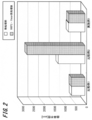
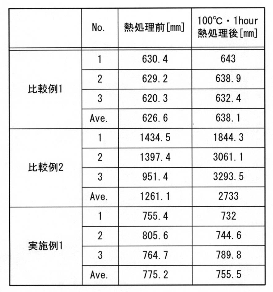
- FIG. 2 is a bar graph showing the average values of the examples and comparative examples in Table 1.
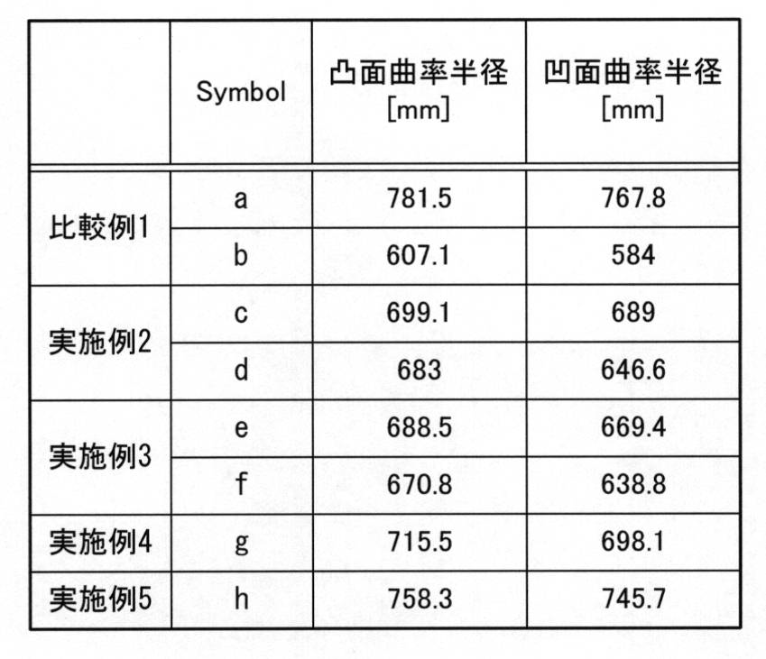
- the radius of curvature is a value including the thickness of the hard coat layer on the convex surface side of the plastic lens.
- Comparative Example 2 in which the photochromic film is provided only on the convex surface of the plastic substrate, the average curvature of 1261.1 mm before the heat curing treatment is 2733.3 mm on average after the heat curing treatment, which is significantly large. . This is because the photochromic film provided on the convex surface of the plastic substrate undergoes thermal contraction during the heat curing process, and stress is generated in a direction that warps the curved surface of the plastic substrate in the opposite direction.
- Example 1 in which the stress correction film was provided on the concave surface of the plastic substrate, the radius of curvature, which had an average value of 775.2 mm before the heat curing process, was 755.5 mm after the heat curing process. . Similar to Comparative Example 1 in which the photochromic film is not provided on the plastic substrate, the radius of curvature hardly changes in Example 1. From this, it can be seen that the stress generated by the thermal contraction of the photochromic film provided on the convex surface of the plastic substrate can be canceled by the stress generated by the thermal contraction of the stress correction film provided on the concave surface of the plastic substrate.
- the refractive power hardly changes immediately after the photochromic film and the stress correction film are formed on the convex and concave surfaces of the plastic substrate.
- the refractive power starts to decrease in the comparative example 2 indicated by the symbol a (line L1) and the symbol b (line L2), and after the heat curing treatment of the hard coat layer, the refractive power is greatly reduced. ing. That is, it can be seen that the photochromic film contracts during the heat curing treatment of the hard coat layer.
- Examples 2 to 5 shown from the symbol c to the symbol h the change in refractive power is small, and the reduction in refractive power can be suppressed.
- the thicknesses of the stress correction films provided on the concave surface of the plastic substrate are different.
- FIG. 4 shows the relationship between the thickness of the stress correction film and the change in refractive power after the overcoating treatment of the hard coat layer.
- the horizontal axis is the thickness of the stress correction film
- the vertical axis is the amount of change in the refractive power of the plastic lens immediately after the hard coat layer is heat-cured.
- the relationship between the thickness of the stress correction film and the amount of change in refractive power is almost linear regardless of the curvature radius of the plastic substrate. For example, if the thickness of the stress correction film is 18 ⁇ m or more, the amount of change in refractive power is less than ⁇ 0.015 diopter, and the amount of change in refractive power is 1 ⁇ 2 compared to the case where no stress correction film is provided. It can be seen that:
- the stress correction film is provided on the concave surface of the plastic substrate, it is possible to suppress deformation due to the contraction of the photochromic film provided on the convex surface. For this reason, a high quality plastic lens can be provided.
- the stress correction film is composed of a photochromic film
- the photochromic film is disposed twice on the convex surface and the concave surface, and the color density can be improved.
Landscapes
- Physics & Mathematics (AREA)
- General Physics & Mathematics (AREA)
- Optics & Photonics (AREA)
- Health & Medical Sciences (AREA)
- Ophthalmology & Optometry (AREA)
- General Health & Medical Sciences (AREA)
- Eyeglasses (AREA)
- Optical Filters (AREA)
- Surface Treatment Of Optical Elements (AREA)
Abstract
Description
特にここでは紫外線硬化型のフォトクロミック膜をレンズ凸面に形成しており、その最適な膜厚は、10μm~50μmとされている。
このため、紫外線の吸収がされない対物側の面にフォトクロミック膜を設けることで、外環境からの紫外線を直接フォトクロミック膜に入射させ、外環境に応じた調光作用を発揮させることを可能としている。
また、これを避けるためには、ハードコート層の硬化温度を低温化する必要があるが、低温でハードコート層を形成すると、十分な耐衝撃性(膜硬度)と、膜密着性を確保することが困難であった。
これにより、プラスチックレンズ全体としての発色濃度を向上させることができる。また、プラスチック基板の凸面に設けられたフォトクロミック膜が損傷しても、応力補正膜によって発色を維持することができる。
1.プラスチックレンズの実施の形態
(1)レンズ構成
(2)プラスチック基板
(3)プライマー層
(4)フォトクロミック膜
(5)応力補正膜
(6)ハードコート層
(7)反射防止膜
2.実施例
(1)レンズ構成
図1は、本発明の実施の形態によるプラスチックレンズ100の断面構成の一例を示す概略構成図である。なお、この図では、構成の概略を示しており、各部位の寸法比等を限定するものではない。
本実施の形態によるプラスチックレンズ100は、例えば片方の面に凸面を有し、もう一方の面に凹面を有するメニスカスレンズ形状である。
なお、反射防止膜6は必ずしも形成しなくてもよいし、またその他の付加的な機能を有する他の膜を設けてもよい。
また、フォトクロミック膜2上、及び応力補正膜3上には、例えば図1に示すように、ハードコート層4,5が積層される。ハードコート層4,5の厚さは、例えば1μm~3μm程度あれば、フォトクロミック膜2や応力補正膜3の保護層として機能させることができる。
また、プラスチック基板1と応力補正膜3の密着性を高めるために、図示しないプライマー層をプラスチック基板1と応力補正膜3の間に介在させてもよい。
このため、凸面に設けられたフォトクロミック膜2の熱収縮によりプラスチック基板11に加えられる応力を、凹面に設けられた応力補正膜3が熱収縮することにより生じる応力によって打ち消すことができる。したがって、レンズの変形を抑制することが可能となり、高品質なプラスチックレンズを提供できる。
プラスチック基板1の凹面側にもフォトクロミック膜を設けることにより、フォトクロミック膜2において吸収されなかった紫外線を凹面側のフォトクロミック膜(応力補正膜3)によって吸収させることができる。
すなわち、応力補正膜3も発色させることで、プラスチックレンズ100に入射した紫外線の利用効率を高めることができ、またプラスチックレンズ100の発色濃度を向上させることが可能である。
例えば、プラスチック基板1の凸面のみにフォトクロミック膜を設けた場合には、プラスチックレンズ100に対する光の透過率は、グレーの色調で23℃の温度環境で約12±1%程度であるのに対し、プラスチック基板1の両面にフォトクロミック膜を設けた場合には、凹面側に入射する紫外線により凹面側のフォトクロミック層も発色し、約9±1%程度の透過率となり発色濃度が増加する。
(2)プラスチック基板
本発明のプラスチックレンズに用いるプラスチック基板1の材料は、特に限定されるものではない。
例えば、メチルメタクリレート単独重合体、メチルメタクリレートと1種以上の他のモノマーとの共重合体、ジエチレングリコールビスアリルカーボネート単独重合体、ジエチレングリコールビスアリルカーボネートと1種以上の他のモノマーとの共重合体、イオウ含有共重合体、ハロゲン共重合体、ポリカーボネート、ポリスチレン、ポリ塩化ビニル、不飽和ポリエステル、ポリエチレンテレフタレート、ポリウレタン、ポリチオウレタン、エピチオ基を有する化合物を材料とする重合体、スルフィド結合を有するモノマーの単独重合体、スルフィドと一種以上の他のモノマーとの共重合体、ポリスルフィドと一種以上の他のモノマーとの共重合体、ポリジスルフィドと一種以上の他のモノマーとの共重合体があげられる。
こうしたプラスチック基板1の材料としては、例えばジエチレングリコールビスアリルカーボネート(PPG社製 CR39)が挙げられる。
また、プラスチック基板1やフォトクロミック膜2,3、ハードコート層4,5、反射防止膜6等の層間にプライマー層を必要に応じて適宜形成してもよい。
このプライマー層に用いる材料は、密着性や耐衝撃性を高め、またプラスチック基板を高屈折率材料により構成する場合は、光学特性に影響を及ぼさないものであれば特に限定しない。例えばポリオール、ポリイソシアネート、ポリイソシアネートのNCO基のブロッキング剤、またこれらに加えて金属酸化物を含む材料を用いることができる。
更に、ジルコニアゾルを混合して成る材料より構成する場合は、より耐候性の低下を抑制できるという利点がある。
フォトクロミック膜2は、フォトクロミック色素を有するコーティング液をプラスチック基板1上に塗布及び硬化することで成膜される。
コーティング液は、硬化性成分(マトリックス)、フォトクロミック色素、重合開始剤、及び、任意に添加される添加剤から構成することができる。コーティング液の調製方法は特に限定されず、所定量の各成分を秤取り、混合することにより行うことができる。
アクリル系材料の場合には、塗布後にUV硬化、ウレタン系材料の場合には熱硬化処理が施され、膜として完成する。
具体的な硬化性成分としては、特開2008-33223号公報、特開2007-77327号公報等に記載されている成分を使用することができる。
例えば、フルギミド化合物、スピロオキサジン化合物、クロメン化合物等のフォトクロミック色素化合物が挙げられる。
また、フォトクロミック色素としては、可視光の短波長側において光異性化反応を発現するものが好ましい。具体的な波長としては、420nm以下であり、好ましくは410nm以下である。この波長の光線は太陽光には多く含まれるが、室内や通常照明下の環境においては存在数が少ない。したがって、室内では本発明のプラスチックレンズの発色が抑制されるが、屋外環境では発色することができる。
応力補正膜3は、重合反応により硬化する硬化性成分と、この硬化性成分の重合反応を促す重合開始剤を含んで構成される。特に、この硬化性成分は、ハードコート層4,5の熱硬化温度において、熱収縮を起こす材料が用いられる。これにより、フォトクロミック膜2の熱収縮によってプラスチック基板1に加えられる応力を、応力補正膜3の熱収縮によってプラスチック基板1に加えられる応力により打ち消すことが可能である。
フォトクロミック膜2と応力補正膜3の硬化性成分と重合開始剤は、全く同一のものであってもよいし、異なっていてもよい。
また、応力補正膜3は、上述の添加剤を含有していてもよい。
なお、この場合、応力補正膜3の構成は、フォトクロミック膜2の構成と同一としてもよい。これにより、フォトクロミック膜2と応力補正膜3を同一のフォトクロミック液によって形成することが可能であり、工程を簡易化することができる。
フォトクロミック膜2、応力補正膜3の上面には、それぞれ硬質膜としてハードコート層4,5が設けられる。
ハードコート層4,5の材料としては、特に限定されず、公知の有機ケイ素化合物及び金属酸化物コロイド粒子よりなるコーティング液を使用することができる。コーティング液を塗布した後、硬化処理によってハードコート層を得ることができる。
この有機ケイ素化合物としては、例えば下記一般式(I)で表される有機ケイ素化合物又はその加水分解物が挙げられる。
(R91)a’(R93)b’Si(OR92)4-(a’+b’)・・・(I)
(式中、R91は、グリシドキシ基、エポキシ基、ビニル基、メタアクリルオキシ基、アクリルオキシ基、メルカプト基、アミノ基、フェニル基等を有する有機基、R92は炭素数1~4のアルキル基、炭素数1~4のアシル基又は炭素数6~10のアリール基、R93は炭素数1~6のアルキル基又は炭素数6~10のアリール基、a'及びb'はそれぞれ0又は1の整数を示す。)
また、上記のR92の炭素数1~4のアシル基としては、例えば、アセチル基、プロピオニル基、オレイル基、ベンゾイル基等が挙げられる。
また、上記R92の炭素数6~10のアリール基としては、例えば、フェニル基、キシリル基、トリル基等が挙げられる。
また、上記R93の炭素数1~4のアルキル基としては、例えば、直鎖又は分岐のメチル基、エチル基、プロピル基、ブチル基、ペンチル基、ヘキシル基等が挙げられる。
そして、上記R93の炭素数1~10のアリール基としては、例えば、フェニル基、キシリル基、トリル基等が挙げられる。
また、ハードコート層4,5上、特にプラスチック基板1の凸面上のハードコート層4上には、反射防止膜6を形成してもよい。この反射防止膜6の材質及び形成方法も特には限定されず、公知の無機酸化物により成る単層、多層膜を使用することができる。
この無機酸化物としては、例えば、二酸化ケイ素(SiO2)、酸化ジルコニウム(ZrO2)、酸化アルミニウム(Al2O3)、酸化ニオブ(Nb2O5)酸化イットリウム(Y2O3)等が挙げられる。
また、有機ケイ素化合物と無機微粒子によって構成され、無機微粒子の種類により屈折率が調整される単層又は多層の有機反射防止膜も使用することができる。
<実施例1>
以下に、本発明によるプラスチックレンズの実施例について説明する。
(1)フォトクロミック液の調製
まずプラスチック製容器にトリメチロールプロパントリメタクリレート20質量部、BPEオリゴマー(2,2-ビス(4-メタクリロイルオキシポリエトキシフェニル)プロパン)35質量部、EB6A(ポリエステルオリゴマーヘキサアクリレート)10質量部、平均分子量532のポリエチレングリコールジアクリレート10質量部、グリシジルメタクリレート10質量部からなるラジカル重合性単量体100質量部を用意した。
プラスチック基板(EYRY(登録商標),S-2.00:HOYA社製)の凸面上に、ポリウレタン骨格にアクリル基を導入したポリウレタンの水分散液(ポリカーボネートポリオール系ポリウレタンエマルジョン)を1100rpmのスピンコーティングによって塗布し、70℃で90分間加熱硬化することによりプライマー層を形成した。その後、プラスチック基板の凹面上にも同じ水分散液を同様に塗布、熱硬化させることにより、プライマー層を形成した。
[1]調整したフォトクロミック液を約2g秤取り、プライマー層が形成された上述のプラスチック基板の凸面に滴下した。そして、600rpmで5秒間スピンコーティングした後、UVランプにより紫外線を90秒照射し、フォトクロミック液を硬化した。
[2]次いで、このプラスチック基板の凹面に、上述のフォトクロミック液を滴下し、600rpmで7秒間スピンコーティングした後、UVランプにより紫外線を40秒照射してフォトクロミック液を硬化し、応力補正膜を形成した。
[3]その後、70℃で90分間のアニール処理を行った。
[4]次に、10℃~15℃に保たれた攪拌機能のついたステンレス容器にSiO2濃度40%の水分散コロイダルシリカ(触媒化成工業(株)製カタロイドSI-40)を280重量部入れ攪拌しながら、0.6Nの塩酸4重量部、酢酸60重量部を添加した。そして、γ-グリシドキシプロピルトリメトキシシラン150重量部を滴下し、24時間攪拌を行った。更に、攪拌しながら、メチルセロソルブを100重量部、イソプロピルアルコール300重量部、n-ブタノール100重量部をこの順序で添加し、均一になった段階で硬化剤としてアルミニウムアセチルアセトン15重量部を添加し、更に1昼夜攪拌を行うことにより、ハードコート液を作製した。
そして、上述のプラスチック基板の凸面側、及び凹面側にこのハードコート液を塗布し、100℃・60分間の加熱硬化処理によってハードコート層を形成した。
プラスチック基板の凹面に、フォトクロミック液を900rpmで12.5秒間、スピンコーティングにより塗布し、応力補正膜を形成したこと以外は、実施例1と同様にして2枚のプラスチックレンズを製造し、上述の工程毎に、プラスチックレンズの屈折力の変化を調べた。
プラスチック基板の凹面に、フォトクロミック液を800rpmで12.5秒間、スピンコーティングにより塗布し、応力補正膜を形成したこと以外は、実施例2と同様にして2枚のプラスチックレンズを製造した。
プラスチック基板の凹面に、フォトクロミック液を700rpmで12.5秒間、スピンコーティングにより塗布し、応力補正膜を形成したこと以外は、実施例2と同様にして1枚のプラスチックレンズを製造した。
プラスチック基板の凹面に、フォトクロミック液を600rpmで12.5秒間、スピンコーティングにより塗布し、応力補正膜を形成したこと以外は、実施例2と同様にして1枚のプラスチックレンズを製造した。
プラスチック基板の凸面及び凹面のどちらにもフォトクロミック膜及び応力補正膜を形成しなかったこと以外は、実施例1と同様にして3枚のプラスチックレンズを製造した。
プラスチック基板の凸面のみにフォトクロミック膜を形成したこと以外は、実施例1と同様にして3枚のプラスチックレンズを製造した。
プラスチック基板の凸面のみにフォトクロミック膜を形成したこと以外は、実施例2と同様にして2枚のプラスチックレンズを製造した。
表1に、実施例1、比較例1,2のプラスチックレンズにおいて、ハードコート層の加熱硬化処理(100℃・60分間)を行う前と、行った後の曲率半径をそれぞれ測定した結果を示す。また、図2は表1における各実施例、比較例の平均値を表す棒グラフである。
なお、曲率半径は、プラスチックレンズの凸面側において、ハードコート層の厚さを含む値とした。
このことから、プラスチック基板の凸面に設けられたフォトクロミック膜の熱収縮によって生じる応力を、プラスチック基板の凹面に設けられた応力補正膜の熱収縮により生じる応力によって打ち消せることがわかる。
また、表3に、プラスチック基板の初期の曲率半径を示す。

ところが、熱アニール直後において、シンボルa(線L1)、シンボルb(線L2)に示す比較例2では屈折力が小さくなり始め、ハードコート層の加熱硬化処理後では、屈折力が大幅に低下している。すなわち、ハードコート層の加熱硬化処理時において、フォトクロミック膜の収縮が生じていることがわかる。
実施例2から実施例5のプラスチックレンズでは、プラスチック基板の凹面に設けた応力補正膜の厚さがそれぞれ異なっている。この応力補正膜の厚さと、ハードコート層の過熱硬化処理後における屈折力の変化との関係を図4に示す。横軸は、応力補正膜の膜厚であり、縦軸は、ハードコート層を加熱硬化した直後のプラスチックレンズの屈折力の変化量である。
また、応力補正膜をフォトクロミック膜によって構成する場合には、凸面と凹面に二重にフォトクロミック膜が配置されることになり、発色濃度を向上させることが可能である。
Claims (4)
- 凹面と凸面を有するメニスカス形状のプラスチック基板と、
前記プラスチック基板の凸面に設けられたフォトクロミック膜と、
前記プラスチック基板の凹面に設けられた応力補正膜と、
を備えた
プラスチックレンズ。 - 前記応力補正膜は、フォトクロミック膜の硬化性成分及び重合開始剤を含有する請求項1に記載のプラスチックレンズ。
- 前記フォトクロミック膜上に形成されたハードコート層を備えた請求項2に記載のプラスチックレンズ。
- 前記応力補正膜は、さらにフォトクロミック色素を含有する請求項1または2に記載のプラスチックレンズ。
Priority Applications (4)
| Application Number | Priority Date | Filing Date | Title |
|---|---|---|---|
| CN201280027305.0A CN103620481A (zh) | 2011-06-03 | 2012-05-31 | 塑料透镜 |
| EP12793473.5A EP2717085A4 (en) | 2011-06-03 | 2012-05-31 | PLASTIC LENS |
| US14/123,303 US20140125947A1 (en) | 2011-06-03 | 2012-05-31 | Plastic lens |
| AU2012263344A AU2012263344A1 (en) | 2011-06-03 | 2012-05-31 | Plastic lens |
Applications Claiming Priority (2)
| Application Number | Priority Date | Filing Date | Title |
|---|---|---|---|
| JP2011-125264 | 2011-06-03 | ||
| JP2011125264 | 2011-06-03 |
Publications (1)
| Publication Number | Publication Date |
|---|---|
| WO2012165579A1 true WO2012165579A1 (ja) | 2012-12-06 |
Family
ID=47259431
Family Applications (1)
| Application Number | Title | Priority Date | Filing Date |
|---|---|---|---|
| PCT/JP2012/064167 WO2012165579A1 (ja) | 2011-06-03 | 2012-05-31 | プラスチックレンズ |
Country Status (6)
| Country | Link |
|---|---|
| US (1) | US20140125947A1 (ja) |
| EP (1) | EP2717085A4 (ja) |
| JP (1) | JPWO2012165579A1 (ja) |
| CN (1) | CN103620481A (ja) |
| AU (1) | AU2012263344A1 (ja) |
| WO (1) | WO2012165579A1 (ja) |
Cited By (7)
| Publication number | Priority date | Publication date | Assignee | Title |
|---|---|---|---|---|
| JP2014145955A (ja) * | 2013-01-30 | 2014-08-14 | Hoya Lense Manufacturing Philippine Inc | 光学物品およびその製造方法 |
| EP2983016A4 (en) * | 2013-04-01 | 2016-11-02 | Hoya Corp | PROCESS FOR PRODUCING DECORATIVE LENSES |
| JP2016538356A (ja) * | 2013-10-11 | 2016-12-08 | トランジションズ オプティカル, インコーポレイテッド | アロファネート保護コーティングを有するフォトクロミック光学物品およびその製造のためのプロセス |
| JP2017219841A (ja) * | 2016-06-03 | 2017-12-14 | カール ツアイス メディテック アクチエンゲゼルシャフト | 光学要素を製造する方法 |
| US9864118B2 (en) | 2014-12-31 | 2018-01-09 | Saint-Gobain Performance Plastics Corporation | Photochromic solar control films |
| JPWO2021201166A1 (ja) * | 2020-03-31 | 2021-10-07 | ||
| WO2024071233A1 (ja) * | 2022-09-29 | 2024-04-04 | 大倉工業株式会社 | 光学フィルム |
Families Citing this family (7)
| Publication number | Priority date | Publication date | Assignee | Title |
|---|---|---|---|---|
| JP6684722B2 (ja) * | 2014-12-04 | 2020-04-22 | 三菱瓦斯化学株式会社 | ポリエステル樹脂を含む機能性シート及びそれを用いたレンズ |
| AU2016232772B2 (en) * | 2015-03-18 | 2021-07-01 | Hoya Optical Labs Of America, Inc. | Crazing resistant coating and method thereof |
| CN106199776A (zh) * | 2016-08-30 | 2016-12-07 | 东兴华鸿光学科技有限公司 | 绿色玻璃镜片 |
| US20190121164A1 (en) * | 2017-10-20 | 2019-04-25 | Luxottica S.R.L. | Eyewear with variable transmission lens |
| CN108121023A (zh) * | 2017-12-28 | 2018-06-05 | 中国科学院长春光学精密机械与物理研究所 | 一种光学薄膜滤光片的制作方法 |
| WO2019189855A1 (ja) * | 2018-03-30 | 2019-10-03 | ホヤ レンズ タイランド リミテッド | 光学物品 |
| CN113093314A (zh) * | 2021-03-31 | 2021-07-09 | 南昌欧菲光电技术有限公司 | 光学膜片和摄像模组 |
Citations (3)
| Publication number | Priority date | Publication date | Assignee | Title |
|---|---|---|---|---|
| JPH11142612A (ja) * | 1997-11-14 | 1999-05-28 | Nikon Corp | フォトクロミックレンズ及びその製造方法 |
| WO2009014086A1 (ja) * | 2007-07-25 | 2009-01-29 | Hoya Corporation | プラスチックレンズの製造方法 |
| JP2011138043A (ja) * | 2009-12-28 | 2011-07-14 | Hoya Corp | プラスチックレンズ及びプラスチックレンズの製造方法 |
Family Cites Families (9)
| Publication number | Priority date | Publication date | Assignee | Title |
|---|---|---|---|---|
| US6392775B1 (en) * | 1998-01-13 | 2002-05-21 | Seagate Technology Llc | Optical reflector for micro-machined mirrors |
| WO2001077740A1 (fr) * | 2000-04-10 | 2001-10-18 | Mitsubishi Gas Chemical Company, Inc. | Stratifie photochrome en resine synthetique transparente |
| KR100812870B1 (ko) * | 2002-05-27 | 2008-03-11 | 가부시끼가이샤 도꾸야마 | 광색성 적층체의 제조 방법 |
| WO2006006363A1 (ja) * | 2004-07-09 | 2006-01-19 | Daishinku Corporation | 光学フィルタおよび光学フィルタの製造方法 |
| CN1858620A (zh) * | 2005-04-29 | 2006-11-08 | 鸿富锦精密工业(深圳)有限公司 | 镀膜光学元件 |
| MX2008016489A (es) * | 2006-06-30 | 2009-02-06 | Tokuyama Corp | Metodo para producir un articulo optico fotocromatico. |
| JP2008033223A (ja) * | 2006-06-30 | 2008-02-14 | Hoya Corp | フォトクロミック膜およびそれを有するフォトクロミックレンズ |
| JP2010026183A (ja) * | 2008-07-17 | 2010-02-04 | Hoya Corp | プラスチックレンズ及びその製造方法 |
| IT1393919B1 (it) * | 2009-04-16 | 2012-05-17 | Marinelli | Metodo per la produzione di elementi ottici fotocromatici ed elementi ottici fotocromatici |
-
2012
- 2012-05-31 JP JP2013518174A patent/JPWO2012165579A1/ja active Pending
- 2012-05-31 AU AU2012263344A patent/AU2012263344A1/en not_active Abandoned
- 2012-05-31 US US14/123,303 patent/US20140125947A1/en not_active Abandoned
- 2012-05-31 WO PCT/JP2012/064167 patent/WO2012165579A1/ja active Application Filing
- 2012-05-31 EP EP12793473.5A patent/EP2717085A4/en not_active Withdrawn
- 2012-05-31 CN CN201280027305.0A patent/CN103620481A/zh active Pending
Patent Citations (3)
| Publication number | Priority date | Publication date | Assignee | Title |
|---|---|---|---|---|
| JPH11142612A (ja) * | 1997-11-14 | 1999-05-28 | Nikon Corp | フォトクロミックレンズ及びその製造方法 |
| WO2009014086A1 (ja) * | 2007-07-25 | 2009-01-29 | Hoya Corporation | プラスチックレンズの製造方法 |
| JP2011138043A (ja) * | 2009-12-28 | 2011-07-14 | Hoya Corp | プラスチックレンズ及びプラスチックレンズの製造方法 |
Non-Patent Citations (1)
| Title |
|---|
| See also references of EP2717085A4 * |
Cited By (12)
| Publication number | Priority date | Publication date | Assignee | Title |
|---|---|---|---|---|
| JP2014145955A (ja) * | 2013-01-30 | 2014-08-14 | Hoya Lense Manufacturing Philippine Inc | 光学物品およびその製造方法 |
| EP2983016A4 (en) * | 2013-04-01 | 2016-11-02 | Hoya Corp | PROCESS FOR PRODUCING DECORATIVE LENSES |
| JP2016538356A (ja) * | 2013-10-11 | 2016-12-08 | トランジションズ オプティカル, インコーポレイテッド | アロファネート保護コーティングを有するフォトクロミック光学物品およびその製造のためのプロセス |
| KR20180113645A (ko) * | 2013-10-11 | 2018-10-16 | 트랜지션즈 옵티칼 인코포레이티드 | 알로파네이트 보호 코팅을 갖는 광색성 광학 제품 및 그의 제조 방법 |
| KR101998044B1 (ko) * | 2013-10-11 | 2019-07-08 | 트랜지션즈 옵티칼 인코포레이티드 | 알로파네이트 보호 코팅을 갖는 광색성 광학 제품 및 그의 제조 방법 |
| US9864118B2 (en) | 2014-12-31 | 2018-01-09 | Saint-Gobain Performance Plastics Corporation | Photochromic solar control films |
| JP2017219841A (ja) * | 2016-06-03 | 2017-12-14 | カール ツアイス メディテック アクチエンゲゼルシャフト | 光学要素を製造する方法 |
| US11474281B2 (en) | 2016-06-03 | 2022-10-18 | Carl Zeiss Meditec Ag | Optical element and method of making an optical element |
| JPWO2021201166A1 (ja) * | 2020-03-31 | 2021-10-07 | ||
| WO2021201166A1 (ja) * | 2020-03-31 | 2021-10-07 | ホヤ レンズ タイランド リミテッド | 光学物品用重合性組成物、光学物品および眼鏡 |
| JP7460756B2 (ja) | 2020-03-31 | 2024-04-02 | ホヤ レンズ タイランド リミテッド | 光学物品用重合性組成物、光学物品および眼鏡 |
| WO2024071233A1 (ja) * | 2022-09-29 | 2024-04-04 | 大倉工業株式会社 | 光学フィルム |
Also Published As
| Publication number | Publication date |
|---|---|
| CN103620481A (zh) | 2014-03-05 |
| EP2717085A4 (en) | 2014-11-19 |
| EP2717085A1 (en) | 2014-04-09 |
| JPWO2012165579A1 (ja) | 2015-02-23 |
| US20140125947A1 (en) | 2014-05-08 |
| AU2012263344A1 (en) | 2014-01-23 |
Similar Documents
| Publication | Publication Date | Title |
|---|---|---|
| WO2012165579A1 (ja) | プラスチックレンズ | |
| US8980431B2 (en) | Primer composition for optical articles and optical articles | |
| US8349397B2 (en) | Plastic lens, manufacturing method thereof, and manufacturing method of hard coat liquid | |
| JP3982933B2 (ja) | 被膜形成用塗布液および合成樹脂製レンズ | |
| JP4161411B2 (ja) | プラスチックレンズの製造方法及びプラスチックレンズ | |
| US20100239776A1 (en) | Method for producing plastic lens | |
| US11526031B2 (en) | Optical article | |
| WO2014119736A1 (ja) | コーティング組成物および光学物品の製造方法 | |
| JP5393429B2 (ja) | 眼鏡用レンズ | |
| JP2011138043A (ja) | プラスチックレンズ及びプラスチックレンズの製造方法 | |
| EP2416203B1 (en) | Photochromic lens manufacturing system, photochromic lens manufacturing device, photochromic lens manufacturing program, recording medium having photochromic lens manufacturing program recorded thereupon, and photochromic lens manufacturing method | |
| US20130142948A1 (en) | Photochromic lens manufacturing system, photochromic lens manufacturing device, photochromic lens manufacturing program, recording medium having photochromic lens manufacturing program recorded thereupon, and photochromic lens manufacturing method | |
| WO2019189875A1 (ja) | 光学物品 | |
| JP6581784B2 (ja) | 眼鏡レンズおよび眼鏡 | |
| JP2008233676A (ja) | 光学物品 | |
| JP2005234528A (ja) | 光学素子および光学素子の製造方法 | |
| JPH11133204A (ja) | 硬化膜付きプラスチックレンズ | |
| JP2014106516A (ja) | フォトクロミックレンズおよびその製造方法 | |
| JP2011215245A (ja) | フォトクロミックレンズ | |
| JP2006201424A (ja) | プラスチックレンズおよびその製造方法 | |
| JP2011186292A (ja) | フォトクロミックレンズ | |
| JP2011180461A (ja) | プラスチックレンズ | |
| JP2013205527A (ja) | フォトクロミックレンズ | |
| JP2005234530A (ja) | プラスチックレンズ | |
| JP2008233917A (ja) | プラスチックレンズの製造方法及びプラスチックレンズ |
Legal Events
| Date | Code | Title | Description |
|---|---|---|---|
| 121 | Ep: the epo has been informed by wipo that ep was designated in this application |
Ref document number: 12793473 Country of ref document: EP Kind code of ref document: A1 |
|
| ENP | Entry into the national phase |
Ref document number: 2013518174 Country of ref document: JP Kind code of ref document: A |
|
| NENP | Non-entry into the national phase |
Ref country code: DE |
|
| WWE | Wipo information: entry into national phase |
Ref document number: 2012793473 Country of ref document: EP |
|
| WWE | Wipo information: entry into national phase |
Ref document number: 14123303 Country of ref document: US |
|
| ENP | Entry into the national phase |
Ref document number: 2012263344 Country of ref document: AU Date of ref document: 20120531 Kind code of ref document: A |