WO2012165534A1 - 粒状物の貯蔵装置 - Google Patents
粒状物の貯蔵装置 Download PDFInfo
- Publication number
- WO2012165534A1 WO2012165534A1 PCT/JP2012/064052 JP2012064052W WO2012165534A1 WO 2012165534 A1 WO2012165534 A1 WO 2012165534A1 JP 2012064052 W JP2012064052 W JP 2012064052W WO 2012165534 A1 WO2012165534 A1 WO 2012165534A1
- Authority
- WO
- WIPO (PCT)
- Prior art keywords
- granular material
- groove
- petroleum resin
- hydrogenated petroleum
- resin pellets
- Prior art date
Links
Images


Classifications
-
- B—PERFORMING OPERATIONS; TRANSPORTING
- B61—RAILWAYS
- B61D—BODY DETAILS OR KINDS OF RAILWAY VEHICLES
- B61D5/00—Tank wagons for carrying fluent materials
- B61D5/08—Covers or access openings; Arrangements thereof
-
- B—PERFORMING OPERATIONS; TRANSPORTING
- B65—CONVEYING; PACKING; STORING; HANDLING THIN OR FILAMENTARY MATERIAL
- B65D—CONTAINERS FOR STORAGE OR TRANSPORT OF ARTICLES OR MATERIALS, e.g. BAGS, BARRELS, BOTTLES, BOXES, CANS, CARTONS, CRATES, DRUMS, JARS, TANKS, HOPPERS, FORWARDING CONTAINERS; ACCESSORIES, CLOSURES, OR FITTINGS THEREFOR; PACKAGING ELEMENTS; PACKAGES
- B65D88/00—Large containers
- B65D88/54—Large containers characterised by means facilitating filling or emptying
-
- B—PERFORMING OPERATIONS; TRANSPORTING
- B65—CONVEYING; PACKING; STORING; HANDLING THIN OR FILAMENTARY MATERIAL
- B65D—CONTAINERS FOR STORAGE OR TRANSPORT OF ARTICLES OR MATERIALS, e.g. BAGS, BARRELS, BOTTLES, BOXES, CANS, CARTONS, CRATES, DRUMS, JARS, TANKS, HOPPERS, FORWARDING CONTAINERS; ACCESSORIES, CLOSURES, OR FITTINGS THEREFOR; PACKAGING ELEMENTS; PACKAGES
- B65D88/00—Large containers
- B65D88/26—Hoppers, i.e. containers having funnel-shaped discharge sections
-
- B—PERFORMING OPERATIONS; TRANSPORTING
- B65—CONVEYING; PACKING; STORING; HANDLING THIN OR FILAMENTARY MATERIAL
- B65G—TRANSPORT OR STORAGE DEVICES, e.g. CONVEYORS FOR LOADING OR TIPPING, SHOP CONVEYOR SYSTEMS OR PNEUMATIC TUBE CONVEYORS
- B65G11/00—Chutes
- B65G11/08—Chutes with discontinuous guiding surfaces, e.g. arranged in zigzag or cascade formation
- B65G11/085—Chutes with discontinuous guiding surfaces, e.g. arranged in zigzag or cascade formation with zig-zag formations
- B65G11/088—Chutes with discontinuous guiding surfaces, e.g. arranged in zigzag or cascade formation with zig-zag formations for bulk
-
- B—PERFORMING OPERATIONS; TRANSPORTING
- B65—CONVEYING; PACKING; STORING; HANDLING THIN OR FILAMENTARY MATERIAL
- B65G—TRANSPORT OR STORAGE DEVICES, e.g. CONVEYORS FOR LOADING OR TIPPING, SHOP CONVEYOR SYSTEMS OR PNEUMATIC TUBE CONVEYORS
- B65G65/00—Loading or unloading
- B65G65/30—Methods or devices for filling or emptying bunkers, hoppers, tanks, or like containers, of interest apart from their use in particular chemical or physical processes or their application in particular machines, e.g. not covered by a single other subclass
- B65G65/32—Filling devices
-
- B—PERFORMING OPERATIONS; TRANSPORTING
- B65—CONVEYING; PACKING; STORING; HANDLING THIN OR FILAMENTARY MATERIAL
- B65G—TRANSPORT OR STORAGE DEVICES, e.g. CONVEYORS FOR LOADING OR TIPPING, SHOP CONVEYOR SYSTEMS OR PNEUMATIC TUBE CONVEYORS
- B65G11/00—Chutes
- B65G11/20—Auxiliary devices, e.g. for deflecting, controlling speed of, or agitating articles or solids
- B65G11/206—Auxiliary devices, e.g. for deflecting, controlling speed of, or agitating articles or solids for bulk
-
- B—PERFORMING OPERATIONS; TRANSPORTING
- B65—CONVEYING; PACKING; STORING; HANDLING THIN OR FILAMENTARY MATERIAL
- B65G—TRANSPORT OR STORAGE DEVICES, e.g. CONVEYORS FOR LOADING OR TIPPING, SHOP CONVEYOR SYSTEMS OR PNEUMATIC TUBE CONVEYORS
- B65G47/00—Article or material-handling devices associated with conveyors; Methods employing such devices
- B65G47/52—Devices for transferring articles or materials between conveyors i.e. discharging or feeding devices
- B65G47/72—Devices for transferring articles or materials between conveyors i.e. discharging or feeding devices transferring materials in bulk from one conveyor to several conveyors, or vice versa
-
- B—PERFORMING OPERATIONS; TRANSPORTING
- B65—CONVEYING; PACKING; STORING; HANDLING THIN OR FILAMENTARY MATERIAL
- B65G—TRANSPORT OR STORAGE DEVICES, e.g. CONVEYORS FOR LOADING OR TIPPING, SHOP CONVEYOR SYSTEMS OR PNEUMATIC TUBE CONVEYORS
- B65G69/00—Auxiliary measures taken, or devices used, in connection with loading or unloading
- B65G69/16—Preventing pulverisation, deformation, breakage, or other mechanical damage to the goods or materials
Definitions
- the present invention relates to a granular material storage device for storing granular materials.
- Patent Document 1 a configuration is known that reduces the pressure acting on stored items that are easily damaged (see, for example, Patent Documents 1 and 2).
- Patent Document 1 a spiral partition plate is arranged at the center of the silo body, and the stored material is dropped by the spiral partition plate to reduce the falling energy, and the pressure between the stored materials is reduced to solidify and bridge. The structure which prevents is taken.
- Patent Document 2 adopts a configuration in which a spiral chute that conveys a raw material from the top to the bottom in a raw material tank, and a speed suppression device that can be rotated in the conveyance direction in the middle of the conveyance path of the spiral chute. ing.
- a stored product may stay on the serpentine partition plate on a gentle slope with a small inclination angle and may be blocked on the way.
- the rate at which the stored item falls gradually increases, the impact applied to the stored item increases, and the stored item may be damaged, consolidated, or cross-linked.
- the structure which provides the spiral chute which has a speed control apparatus of patent document 2 by providing the structure which rotates, there exists a possibility that a structure may become complicated and manufacture and maintenance management may become complicated.
- the stored material stays on the serrated partition plate on a gentle slope where the inclination angle of the spiral chute is small, and the stored material tends to stay at the position of the speed control device in the case of a relatively light stored material such as grain or resin pellets. .
- a relatively light stored material such as grain or resin pellets.
- the stored material staying from the spiral chute overflows and falls, and the stored material is damaged by the impact of the drop.
- the material is also stored on the spiral chute and stays at the position of the speed control device with the conveyance flow path open. For this reason, the stored product is sandwiched between the speed control device and the spiral chute, and even when the stored material is discharged, the speed control device may not return to the state of closing the original conveyance flow path, and the speed control function may be impaired. is there.
- An object of the present invention is to provide a storage device for granular materials that can be stored well without damaging the granular materials.
- the granular material storage device of the present invention is a granular material storage device having an input port at the top and a discharge port at the bottom, and the granular material charged from the input port is allowed to flow obliquely downward.
- a flow path that suppresses breakage is provided, and the flow path includes a speed reducing unit that slows down the flow rate of the granular material by reversing the flow direction of the granular material.
- the flow velocity is reduced by reversing the flow direction by the reduction means. For this reason, since the impact which falls to the granular material thrown in from the insertion opening falls, it can prevent that a granular material breaks.
- the said flow path is set as the structure provided with the member which forms the groove-like structure which flows the said granular material diagonally downward.
- the structure which flows a granular material diagonally downward is obtained by the member of the simple structure which forms a groove-shaped structure.
- the member overflows from the member that forms the groove-like structure and wraps around the member. For this reason, there is no inconvenience that the particulate matter is clogged in the middle of the flow path, and inconvenience that a dead space that cannot be stored is generated.
- a plurality of members that form the groove-like structure are arranged in the vertical direction, and each of the members that form the groove-like structures adjacent to each other in the vertical direction is inclined in the direction in which the granular material flows,
- the speed reduction means is preferably provided between members forming the groove-like structure adjacent to each other in the vertical direction.
- the speed reducing means is a plate-like member that comes into contact with a granular material flowing down from a lower part of the member forming the groove-like structure.
- the flow direction of the granular material that flows obliquely downward through the member forming the groove-like structure can be reversed by abutting and rebounding the plate-like member having a simple structure. For this reason, it is possible to easily reduce the flow velocity by reversing the flow direction, and it is possible to suppress the breakage of the granular material with a simple structure.
- variety which flows the said granular material in the member which forms the said groove-like structure is set as the structure where the upper part is wider than the lower part.
- the granular material falling from the lower part of the member forming the groove-like structure and contacting the plate-like member can surely fall onto the upper part of the member forming the other groove-like structure located immediately below. For this reason, it is possible to prevent the inconvenience that the particulate matter bounced back in contact with the plate-like member is spilled and damaged.
- the speed reducing means is a hopper-like member that receives a granular material that flows down from a lower part of the member that forms the groove-like structure.
- the particulate matter received by the hopper-like member is dropped to a member that forms another groove-like structure located below without being bounced down and spilled downward in the opposite direction. For this reason, it can prevent that a granular material is damaged by the impact which spills from the member which forms a groove-shaped structure.
- the granular material is preferably a hydrogenated petroleum resin pellet.
- a hydrogenated petroleum resin pellet Even when hydrogenated petroleum resin pellets are easily damaged, damage during storage can be satisfactorily suppressed. For this reason, for example, when preparing a hot melt adhesive by mixing hydrogenated petroleum resin pellets with a base polymer, the hydrogenated petroleum resin pellets are broken and the particle size distribution fluctuates. The inconvenience that the setting and adjustment of the production conditions of the hot melt adhesive becomes complicated can also be prevented.
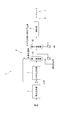
- the block diagram which shows schematic structure of the manufacturing plant of the hydrogenated petroleum resin pellet which concerns on the storage apparatus of the granular material of this invention.
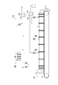
- the schematic structure figure which shows the granulation part in the manufacturing plant of the said hydrogenated petroleum resin pellet.
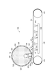
- the schematic structure figure which shows the conveyance part in the manufacturing plant of the said hydrogenated petroleum resin pellet.
- the schematic block diagram which shows the storage part in the manufacturing plant of the said hydrogenated petroleum resin pellet.
- the perspective view which notched a part which shows the storage hopper of the said storage part.
- the front view which shows the groove-shaped inclination flow path in the said storage part.
- the side view which shows the said groove-shaped inclination flow path.
- a storage device for hydrogenated petroleum resin pellets as a storage device for a granulated product of the present invention will be described with reference to the drawings.
- a hydrogenated petroleum resin pellet is illustrated as a granular material, it can apply not only to this but to various granular materials, and the granular material which is easy to be damaged especially by an impact can be made into object.
- the structure of the manufacturing plant which manufactures the hydrogenated petroleum resin pellet provided with the storage device of the hydrogenated petroleum resin pellet is demonstrated below.
- a hydrogenated petroleum resin pellet manufacturing plant 1 is a plant for manufacturing hydrogenated petroleum resin pellets from hydrogenated petroleum resin raw materials.
- the production plant 1 includes a polymerization reaction unit 2, a hydrogenation reaction unit 3, a hydrogenation solvent recovery unit 4, a granulation unit 5, a transport unit 6, a storage unit 7, and a control unit (not shown). I have.
- the polymerization reaction unit 2 performs a polymerization reaction in which a cyclopentadiene compound and a vinyl aromatic compound are thermally polymerized to obtain a copolymer.
- the polymerization reaction unit 2 includes a polymerization reaction tank for performing a thermal polymerization reaction with a cyclopentadiene compound and a vinyl aromatic compound that are hydrogenated petroleum resin raw materials using a solvent.
- the cyclopentadiene compound include cyclopentadiene, methylcyclopentadiene, and ethylcyclopentadiene, as well as dimers and co-dimers thereof.
- Examples of vinyl aromatic compounds include styrene, ⁇ -methylstyrene, vinyltoluene and the like.
- Examples of the solvent include aromatic solvents, naphthene solvents, aliphatic hydrocarbon solvents, and the like. Specifically, benzene, toluene, xylene, cyclohexane, methylcyclohexane, dimethylcyclohexane, ethylcyclohexane and the like can be suitably used.
- the solvent is appropriately recovered from the polymerization reaction tank and reused.
- the recovered solvent usually contains a low molecular weight substance having a molecular weight of about 200 to 350.
- the concentration of the low molecular weight substance in the solvent when reused as the solvent for thermal polymerization is at least 4% by mass or less.
- the low molecular weight substance is separated and removed separately or diluted with a new solvent to obtain a low molecular weight concentration of 4% by mass or less, and at the start of the polymerization reaction. Used as a solvent for polymerization.
- the polymerization reaction tank is a reactor that performs polymerization under pressure and heating, and includes a stirrer and a heating device (not shown). Then, the first raw material tank, the second raw material tank, and the solvent tank of the solvent recovery unit are connected to the polymerization reaction tank, and the cyclopentadiene compound, the vinyl aromatic compound, and the solvent are appropriately introduced. In addition, the obtained copolymer is discharged from the bottom of the polymerization reaction tank and used for the next hydrogenation reaction.
- the amount of the polymerization solvent used is 50 to 500 parts by mass with respect to 100 parts by mass of the monomer mixture.
- the temperature of the solvent is heated to 100 ° C., preferably 150 ° C. or more at the start of thermal polymerization.
- copolymerization is performed while a mixture of a cyclopentadiene compound and a vinyl aromatic compound is added in portions in a heated solvent.
- the divided addition time is usually 0.5 to 5 hours, and it is desirable to add them equally.
- the reaction temperature is 150 ° C. or more and 350 ° C.
- the polymerization reaction tank has a softening point of 60 ° C. or higher and 130 ° C. or lower, a vinyl aromatic compound content of 30% by mass or higher and 90% by mass or lower, and a bromine value of 30 g / 100 g or higher depending on the conditions of these thermal polymerizations.
- a copolymer having 90 g / 100 g or less and a number average molecular weight of 400 to 1000 is obtained.
- the hydrogenation reaction section 3 performs a hydrogenation reaction in which hydrogen is added to the copolymer produced by thermal polymerization in the polymerization reaction section 2 to obtain a hydrogenation reaction product.
- the hydrogenation reaction section 3 includes a plurality of hydrogenation reaction towers for performing hydrogenation reaction by adding hydrogen to the copolymer produced by thermal polymerization in the polymerization reaction section 2 in the presence of a hydrogenation solvent. ing.
- the hydrogenation solvent include cyclohexane, methylcyclohexane, dimethylcyclohexane, ethylcyclohexane, tetrahydrofuran, and the like.
- the hydrogenation reaction tower is a tower filled with a hydrogenation reaction catalyst, and may be used in multiple stages.
- the hydrogenation reaction catalyst nickel, palladium, cobalt, platinum, rhodium-based catalyst or the like is used.
- the hydrogenation reaction column hydrogenates the copolymer with hydrogen in the presence of a hydrogenation reaction catalyst at a temperature of 120 to 300 ° C., a reaction pressure of 1 to 6 MPa, and a reaction time of 1 to 7 hours. .
- the softening point is 70 ° C. or more and 140 ° C.
- the vinyl aromatic compound content is 0% by mass or more and 35% by mass or less
- the bromine value is 0 g / 100 g or more and 30 g / 100 g or less
- number average A hydrogenation reaction product having a molecular weight of 400 to 1000 is obtained.
- the hydrogenation reaction section 3 after the hydrogenation reaction in the hydrogenation reaction tower, the gas phase containing unreacted hydrogen is separated and appropriately recovered and treated outside the system.
- the hydrogenation solvent recovery unit 4 separates and removes the hydrogenation solvent from the hydrogenation reaction product.
- the hydrogenated solvent recovery unit 4 includes a solvent evaporation tank 41 as a first evaporator, a thin film evaporator 42 as a second evaporator, and the like.
- the solvent evaporation tank 41 is connected to the hydrogenation reaction unit 3, and separates and recovers the hydrogenation solvent from the hydrogenation reaction product obtained in the hydrogenation reaction unit 3.
- the evaporated hydrogenated solvent is separately collected and reused as a hydrogenated solvent used in the hydrogenation reaction in the hydrogenation reaction unit 3.
- the thin film evaporator 42 is connected to the solvent evaporation tank 41 and evaporates and recovers the hydrogenated solvent remaining in the hydrogenation reaction product.
- the evaporated hydrogenated solvent and low molecular weight substance are separately collected and reused as appropriate as the hydrogenated solvent used in the hydrogenation reaction in the hydrogenation reaction section 3 in accordance with the physical properties of the hydrogenated petroleum resin pellets to be produced. Is done.
- an addition unit for adding an antioxidant is provided between the solvent evaporation tank 41 and the thin film evaporator 42 of the hydrogenated solvent recovery unit 4.
- the addition part of the antioxidant adds the antioxidant to the hydrogenation reaction product from which most of the hydrogenation solvent has been removed in the solvent evaporation tank 41.
- the solvent for dissolving the antioxidant the remaining hydrogenated solvent together with the solvent in which the antioxidant is dissolved is separated by the evaporation treatment by the thin film evaporator 42 in the subsequent stage, and the recovered hydrogenated solvent is reused for the hydrogenation reaction. can do. This is because the hydrogenation reaction is not affected.
- the solvent in which the antioxidant is dissolved is separated and recovered from the hydrogenation reaction product together with the hydrogenation solvent by the thin film evaporator 42 on the downstream side.
- the granulating unit 5 granulates the molten resin, which is a hydrogenation reaction product from which the hydrogenation solvent has been removed and the antioxidant is added, into pelletized hydrogenated petroleum resin pellets.
- the granulation unit 5 includes a granulator 50A and a granulation air cooling unit 50B as shown in FIG.
- the granulator 50A includes a granulator main body 52 and a cooling conveyor 53.
- the granulator main body 52 is disposed in the granulation casing 51 so as to face the upstream end side in the transport direction of the cooling conveyor 53.
- the granulator main body 52 has a die 52B that discharges molten resin along the axial direction from the outer peripheral surface of the body portion 52A to a body portion 52A having a cylindrical heating unit (not shown).
- the granulator main body 52 has a cylindrical rotating body 52C that fits rotatably on the outer peripheral surface of the body portion 52A.
- the rotating body 52C has a plurality of discharge holes 52D like a punching metal.
- the cooling conveyor 53 includes a pair of pulleys 53A and a metal belt 53B that is a metal endless belt that is rotatively looped around the pulleys 53A. Further, the cooling conveyor 53 is provided with a cooling section 53D that cools the metal belt 53B by ejecting cooling water 53C from the back surface of the metal belt 53B. Note that the cooling method of the metal belt 53B is not limited to the method of ejecting the cooling water 53C, and any method such as blowing cool air can be applied.
- the granulation air cooling unit 50B includes an air introduction path 54B having a blower 54A for introducing air into the granulation casing 51, and an intake blower 54C for sucking air in the granulation casing 51. And an intake passage 54E having a filter 54D.
- the air introduction path 54 ⁇ / b> B is provided so that air can be introduced into the granulation casing 51 at positions corresponding to the downstream end of the cooling conveyor 53 and the two intermediate positions.
- the intake passage 54 ⁇ / b> E is located at three positions in the vicinity of the granulator main body 52, which is the upstream end of the cooling conveyor 53, and two positions at intermediate positions in the transport direction of the cooling conveyor 53, that is, on the cooling conveyor 53.
- the intake passage 54E captures and removes the low molecular weight mist from the air containing the low molecular weight mist in the granulation casing 51 by the filter 54D and exhausts only the air.
- the intake / exhaust at the intermediate position is appropriately designed corresponding to the different softening points of the hydrogenated petroleum resin pellets to be produced. That is, it is preferable to have a structure capable of intake / exhaust at a plurality of positions so that even when the range until the molten resin solidifies varies depending on the product.
- an inertial collision filter As the filter 54D, an inertial collision filter, a blocking filter, an electrostatic adsorption filter, a brown diffusion filter, or the like is used, and a glass fiber filter is particularly preferable. That is, since the low molecular weight mist is composed of fine high-viscosity fine particles having a mist diameter of 1 ⁇ m or less, the effect of collecting particles whose mass is ignored in addition to the inertial collision effect (collection effect by Brownian diffusion) is obtained. A glass fiber filter is preferred. Further, the pressure loss of the filter 54D is preferably set to 0.5 kPa or more and 2.5 kPa or less from the relationship with the filtration area.
- a scraper 55 that scrapes off the hydrogenated petroleum resin pellets solidified on the metal belt is disposed in the granulation casing 51 at the downstream end of the cooling conveyor 53. ing. Further, the granulating casing 51 is connected to a transport unit 6 that is positioned at the downstream end of the cooling conveyor 53 and transports to the storage unit 7.
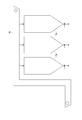
- the transport unit 6 transports the hydrogenated petroleum resin pellets granulated by the granulation unit 5 to the storage unit 7. As shown in FIG. 4, the transport unit 6 includes a chute 61 connected to the granulating unit 5, a transport conveyor 62 connected to the chute 61, and a bucket conveyor 65 (see FIG. 5). Yes.
- One end of the chute 61 is connected to the lower portion of the granulating casing 51 at the downstream end of the cooling conveyor 53 and the other end extends downward, and one end is connected to the lower end of the upper chute 61A.
- the other end has an upper chute portion 61A and a lower chute portion 61B extending to the opposite side, and is formed in a V shape in a side view.
- the upper chute portion 61A and the lower chute portion 61B are provided such that the inclined surface 63 on which the hydrogenated petroleum resin pellets flow is inclined at an inclination angle of 44 ° to 75 ° with respect to the horizontal plane.
- the hydrogenated petroleum resin pellets are retained on the inclined surface 63, and the hydrogenated petroleum resin pellets that are retained by switching the product to be manufactured are newly produced.
- the inconvenience of being mixed with the product to be produced occurs.
- the inclination angle of the inclined surface 63 is steeply greater than 75 °, the flowing speed of the hydrogenated petroleum resin pellets flowing down on the inclined surface 63 increases, and the hydrogenated petroleum resin pellets may be damaged by the falling impact. Because there is.
- the transport conveyor 62 includes a conveyor casing 62A, a belt conveyor 62B, and a recovery hopper 62C.
- the belt conveyor 62B is disposed in a conveyor casing 62A connected to the lower end of the lower chute 61B at one end, and conveys hydrogenated petroleum resin pellets flowing down the lower chute 61B.
- the belt conveyor 62B includes a pair of conveying pulleys 62B1 and an endless belt 62B2 that is looped around the conveying pulleys 62B1.
- the other end of the conveyor housing 62A is provided with a charging chute (not shown) for charging the hydrogenated petroleum resin pellets conveyed by the belt conveyor 62B into the storage unit 7.
- the charging chute is connected to a bucket conveyor that conveys hydrogenated petroleum resin pellets to the storage unit 7.
- the collection hopper 62C has an opening formed with a diameter increasing upward, and a plurality of collection hoppers 62C are provided on the lower surface of the conveyor casing 62A, positioned below the belt conveyor 62B.
- the recovery hopper 62C is formed such that the inner surface is inclined at an angle larger than the angle of repose at which the powder of the hydrogenated petroleum resin pellets collapses, specifically, 70 ° or more with respect to the horizontal plane.
- the collection hoppers 62C are not limited to a plurality of collection hoppers, and are located at least below the lower chute 61B so long as the hydrogenated petroleum resin pellets flowing down the lower chute 61B and spilling from the belt conveyor 62B can be collected. There may be only one.
- a screw conveyor (not shown) is provided below the collection hopper 62C, and the hydrogenated petroleum resin pellets and the granular materials collected in each collection hopper 62C can be conveyed outside the collection hopper 62C. Yes.
- the configuration is not limited to the configuration in which the screw conveyor is provided below the collection hopper 62C, and a configuration in which a belt conveyor or the like is provided or a discharge port that can be simply opened and closed may be provided.
- the storage unit 7 stores the hydrogenated petroleum resin pellets conveyed by the conveyance unit 6 so as to be appropriately removable. As shown in FIG. 5, the storage unit 7 includes a plurality of storage hoppers 71 and a switching unit (not shown) that inputs hydrogenated petroleum resin pellets transported by the bucket conveyor 65 of the transport unit 6 to a predetermined storage hopper 71. It is equipped with.
- the storage hopper 71 is formed, for example, with an inner peripheral surface having a cylindrical shape and a bottom portion having a reduced diameter in the vertical direction.
- a pair of openings, not shown, into which the hydrogenated petroleum resin pellets dropped from the switching unit are placed are positioned in the diametrical direction in the vicinity of the periphery.
- a discharge port that is opened and closed by a discharge valve (not shown) that discharges hydrogenated petroleum resin pellets to be stored is formed at the lower end of the storage hopper 71.
- a pair of grooved inclined channels 72 which are the channels shown in FIGS. 6 to 8, are disposed in the diameter direction of the storage hopper 71, respectively.
- the storage hopper 71 is not limited to a cylindrical shape, and can be designed in a suitable shape such as a prismatic shape.
- the grooved inclined flow path 72 flows the hydrogenated petroleum resin pellets introduced from the inlet of the storage hopper 71 obliquely downward, and suppresses the damage of the hydrogenated petroleum resin pellets.
- the groove-like inclined flow path 72 includes a support member (not shown) provided on the inner peripheral surface of the storage hopper 71 from the inlet to the bottom of the storage hopper 71, and a plurality of groove-like shapes arranged on the support member in the vertical direction. And an inclined channel member 72B.
- the support member is provided with a mounting bracket 72A1 as shown in FIG.
- the mounting bracket 72A1 is formed by bending a steel plate into an L-shaped cross section, and a plurality of mounting brackets 72A1 are provided at predetermined intervals on the inner peripheral surface of the storage hopper 71. As shown in FIGS. 7 to 9, a plurality of support members are attached in the opposite direction so that each of the plurality of vertically adjacent groove-like inclined flow path members 72B reverses the flowing direction of the hydrogenated petroleum resin pellets.
- the groove-shaped inclined flow path member 72B is a member that is formed of, for example, a stainless steel plate or the like and forms a groove-shaped structure that allows the hydrogenated petroleum resin pellets to flow obliquely downward.
- the grooved inclined flow path member 72B is formed by bending upward on both sides of the inclined plate 72B1 and the inclined plate 72B1 inclined at an angle greater than 37 °, which is the angle of repose at which the hydrogenated petroleum resin pellets do not collapse. It has a side plate 72B2 and a plate-like member 72B3 serving as a speed reduction means that is bent upward at an end located on the upper side, which is one end of the inclined plate 72B1, to form a groove-like structure.
- the grooved inclined flow path member 72B is not limited to a stainless steel plate, and can be formed of various materials such as a surface-treated steel plate.
- the inclined plate 72B1 is formed in a trapezoidal shape that becomes gradually narrower from one end to the other end. That is, the width dimension on the lower end side is made narrow so that the hydrogenated petroleum resin pellets falling from the lower end of the inclined plate 72B1 will surely hit the plate-like member 72B3 of the groove-like inclined flow path member 72B located immediately below. .
- the width dimension of the inclined plate 72B1 may be appropriately set according to the production amount Q of hydrogenated petroleum resin pellets in the granulation unit 5.
- the height dimension H of the hydrogenated petroleum resin pellets flowing down at the lower end of the inclined plate 72B1 can be calculated.
- This height dimension H may be set to a state in which the hydrogenated petroleum resin pellets to flow down flow in a single layer without overlapping, because the hydrogenated petroleum resin pellets are in contact with each other and do not hinder the flow. preferable.
- the width dimension of the inclined plate 72B1 can be set.
- the side plate 72B2 is formed so that the height dimension decreases from one end of the inclined plate 72B1 to the other end. That is, when hydrogenated petroleum resin pellets are introduced into the storage hopper 71 and the amount of storage increases, as shown in FIG. 10, it overflows from the side plate 72B2 of the grooved inclined channel member 72B. From this, in the vicinity of the plate-like member 72B3 with which the falling hydrogenated petroleum resin pellets abut, the height is set so as not to bounce off the side plate 72B2, and the hydrogenated petroleum resin pellets are formed low on the lower end side so as to easily overflow. It is preferable. Therefore, it is preferable from the viewpoint of manufacturability to form the side plate 72B2 in a triangular shape.
- the plate-like member 72B3 reverses the flow direction of the hydrogenated petroleum resin pellets by abutting the hydrogenated petroleum resin pellets flowing down from the lower part of the other grooved inclined channel member 72B disposed above, thereby Reduce the flow rate of the resin pellets.
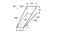
- This plate-like member 72B3 has a high velocity of 200 mm, which has the same potential energy, since the falling speed of the hydrogenated petroleum resin pellets charged into the storage hopper 71 is a vertical velocity from the height of 200 mm. It becomes possible to contact the hydrogenated petroleum resin pellet which falls reliably by forming in the size.
- FIG. 9 what was formed in 150 mm is illustrated.
- the plate-like member 72B3 is provided with a surface desired for the inclined plate 72B1 at an angle of ⁇ 180 °-(more than the repose angle of the hydrogenated petroleum resin pellet) ⁇ with respect to the inclined plate 72B1. That is, the groove-like inclined flow path member 72B is disposed on the inner peripheral surface of the storage hopper 71 by the support member, and the inclined plate 72B1 has a repose angle or more with respect to the horizontal plane, and the plane of the plate-like member 72B3 is It is formed in a state along the vertical direction.
- the falling speed is slower than 1.98 m / sec.
- the inclination angle is 37 ° to 45 °, preferably 40 °
- the distance from the plate-like member 72B3 to the plate-like member 72B3 of the groove-like inclined flow path member 72B located immediately below is 405 mm to 550 mm.
- it is preferably formed to 450 mm.
- each of the plurality of groove-like inclined flow path members 72B has an inclination direction of the inclined plate 72B1 in the inclination direction of another groove-like inclined flow path member 72B disposed immediately above.
- the hydrogenated petroleum resin pellets falling from the other groove-like inclined flow path member 72B arranged immediately above are arranged in a positional relationship in contact with the plate-like member 72B3. That is, each of the plurality of grooved inclined flow path members 72B is arranged under the following three preconditions. 1.
- the other is disposed immediately above and above the side plate 72B2 of the groove-shaped inclined flow path member 72B.
- the lower end of the groove-like inclined flow path member 72B is positioned, and the groove-like inclined flow path members 72B are arranged so as not to overlap each other in a side view. That is, as shown in FIG. 12, when a line with an angle of repose of 37 ° is drawn from the upper end edge of the plate-like member 72B3, other grooves arranged immediately above from the line to the groove-like inclined flow path member 72B side. It arrange
- each of the plurality of grooved inclined flow path members 72B is preferably arranged as shown in FIG.
- the plate-like member 72B3 may not be provided in the groove-like inclined channel member 72B located at the uppermost part in the groove-like inclined channel 72.
- the structure which flows a hydrogenated petroleum resin pellet diagonally downward is formed by the groove-shaped inclined flow path member 72B of the simple structure which forms a groove-shaped structure. Further, when the charged hydrogenated petroleum resin pellets are gradually accumulated and piled up to the groove-like inclined channel member 72B, as shown in FIG. 10, the grooved inclined channel member 72B overflows from the groove-like inclined channel member 72B.
- the grooved inclined flow path member 72B is configured by a grooved inclined flow path member 72B having a grooved structure that wraps around below the path member 72B. For this reason, there is no inconvenience that the hydrogenated petroleum resin pellets are clogged in the middle, and inconvenience that a dead space that cannot be stored is generated.
- the grooved inclined flow is performed with the plate-like member 72B3 positioned between the grooved inclined flow path members 72B that are arranged in the vertical direction so that the flowing direction of the hydrogenated petroleum resin pellets is opposite.
- a path 72 is formed.
- the flow direction of the hydrogenated petroleum resin pellet which flows through the groove-shaped inclination flow path member 72B diagonally downward is reversed by making it contact
- the groove width of the grooved inclined channel member 72B is formed so that the upper part is wider than the lower part, it falls from the lower part of the grooved inclined channel member 72B to form a plate shape.
- the hydrogenated petroleum resin pellets in contact with the member 72B3 can be reliably dropped onto the upper part of the other groove-like inclined flow path member 72B located immediately below without spilling down. For this reason, it is possible to prevent the hydrogenated petroleum resin pellets that have come into contact with the plate-like member 72B3 and bounced off from being spilled and damaged.
- the structure which stores the hydrogenated petroleum resin pellet which is easy to break and it is set as the structure which can prevent a breakage and can be stored favorably. For this reason, for example, when preparing a hot melt adhesive by mixing hydrogenated petroleum resin pellets with a base polymer, the hydrogenated petroleum resin pellets are broken and the particle size distribution fluctuates. The inconvenience that the setting and adjustment of the production conditions of the hot melt adhesive becomes complicated can also be prevented.
- the grooved inclined flow path member 72B is formed in a chute shape having a U-shaped cross section having the inclined plate 72B1 and the side plate 72B2, but this is not restrictive.
- hydrogenated petroleum resin pellets can flow down diagonally in any shape that forms a concave groove structure, such as one in which the inclined plate 72B1 is curved or bent in the center with a V-shaped cross section. Any shape can be used.
- the plate-shaped member 72B3 as a structure which makes the speed
- a hopper-like member that temporarily stores hydrogenated petroleum resin pellets may be used instead of the plate-like member 72B3.
- the hydrogenated petroleum resin pellets dropped from the groove-like inclined channel member 72B and received by the hopper-like member are dropped to the other groove-like inclined channel member 72B positioned below without splashing and falling down. And is swept downward in the opposite direction. For this reason, even in the configuration using the hopper-like member, it is possible to prevent the hydrogenated petroleum resin pellet from being damaged by the impact spilling from the groove-like inclined flow path member 72B, as in the above embodiment.
- the hopper-like member may be configured such that, for example, a falling hydrogenated petroleum resin pellet is brought into contact with the inner peripheral surface of the hopper-like member and dropped into the lower groove-like inclined flow path member 72B, or temporarily such as an hourglass.
- Any shape can be used as long as the hydrogenated petroleum resin pellets can be slowed down and dropped into the lower groove-shaped inclined flow path member 72B, such as a configuration that overflows and drops into the lower groove-shaped inclined flow path member 72B. Can do.
- the present invention is not limited to the plate-like member 72B3 or the hopper-like member, and any member that exhibits a speed reduction function for reducing the speed of the hydrogenated petroleum resin pellets may be used.
- the present invention is used in a storage device for storing granular materials that are easily damaged by external impacts, such as hydrogenated petroleum resin pellets.
Abstract
水添石油樹脂ペレットを貯留する貯留ホッパー内に、投入口から投入された水添石油樹脂ペレットを斜め下方に流す溝状傾斜流路を設ける。溝状傾斜流路は、傾斜板(72B1)および側板(72B2)を有し溝状構造を形成する溝状傾斜流路部材(72B)を、水添石油樹脂ペレットを流す方向が反対方向となるように、上下方向に複数配置して構成する。上下に隣接する溝状傾斜流路部材(72B)のそれぞれは、溝状傾斜流路部材(72B)から落下する水添石油樹脂ペレットが直近下方の溝状傾斜流路部材(72B)の板状部材(72B3)に当接して流れる方向を反転させ、水添石油樹脂ペレットの流速が減速する状態に配置する。投入口から投入された水添石油樹脂ペレットに加わる下方へ落下する衝撃が減少し、貯蔵の際の水添石油樹脂ペレットの破損を防止できる。
Description
本発明は、粒状物を貯蔵する粒状物の貯蔵装置に関する。
従来、サイロやホッパーなどの貯蔵装置において、損傷しやすい貯蔵物に対して作用する圧力を低減させる構成が知られている(例えば、特許文献1,2参照)。
特許文献1は、サイロ本体の中心に、らせん仕切板を配設し、らせん仕切板によって貯蔵物を落下させ、落下エネルギーを軽減させるとともに、貯蔵物相互の圧力を小さくして固結や架橋を防止する構成が採られている。
特許文献2は、原料槽内に上部から下方へ向けて原料を搬送するスパイラルシュートと、このスパイラルシュートの搬送流路の途中に搬送方向へ回動可能なスピード抑制装置を設けた構成が採られている。
特許文献1は、サイロ本体の中心に、らせん仕切板を配設し、らせん仕切板によって貯蔵物を落下させ、落下エネルギーを軽減させるとともに、貯蔵物相互の圧力を小さくして固結や架橋を防止する構成が採られている。
特許文献2は、原料槽内に上部から下方へ向けて原料を搬送するスパイラルシュートと、このスパイラルシュートの搬送流路の途中に搬送方向へ回動可能なスピード抑制装置を設けた構成が採られている。
しかしながら、特許文献1に記載のらせん仕切板を設ける構成では、傾斜角が小さい緩斜面ではせらん仕切板上に貯蔵物が滞留し、途中で閉塞するおそれがある。また、傾斜角が大きい急斜面では貯蔵物が落下する速度が次第に速くなり、貯蔵物に加わる衝撃が大きくなり、貯蔵物が破損したり、固結したり、架橋したりするなどの不都合を生じるおそれがある。
また、特許文献2に記載のスピード抑制装置を有するスパイラルシュートを設ける構成では、回動する構成を設けることで、構造が複雑となり、製造および保守管理が煩雑となるおそれがある。また、スパイラルシュートの傾斜角が小さい緩斜面ではせらん仕切板上に貯蔵物が滞留、特に貯蔵物が穀物や樹脂ペレットなどの比較的に軽量な貯蔵物ではスピード抑制装置の位置で滞留し易い。このため、スパイラルシュートから滞留する貯蔵物が溢れて落下し、落下の衝撃で貯蔵物が損傷するなどの不都合を生じるおそれがある。さらに、貯蔵物の貯蔵量が増えると、スパイラルシュート上にも貯留しスピード抑制装置の位置でも搬送流路を開いたままの状態で滞留することとなる。このため、スピード抑制装置とスパイラルシュートとの間に貯蔵物が挟まり、貯蔵物を排出した際でもスピード抑制装置が元の搬送流路を閉じる状態に戻らなくなり、スピード抑制の機能が損なわれるおそれがある。
また、特許文献2に記載のスピード抑制装置を有するスパイラルシュートを設ける構成では、回動する構成を設けることで、構造が複雑となり、製造および保守管理が煩雑となるおそれがある。また、スパイラルシュートの傾斜角が小さい緩斜面ではせらん仕切板上に貯蔵物が滞留、特に貯蔵物が穀物や樹脂ペレットなどの比較的に軽量な貯蔵物ではスピード抑制装置の位置で滞留し易い。このため、スパイラルシュートから滞留する貯蔵物が溢れて落下し、落下の衝撃で貯蔵物が損傷するなどの不都合を生じるおそれがある。さらに、貯蔵物の貯蔵量が増えると、スパイラルシュート上にも貯留しスピード抑制装置の位置でも搬送流路を開いたままの状態で滞留することとなる。このため、スピード抑制装置とスパイラルシュートとの間に貯蔵物が挟まり、貯蔵物を排出した際でもスピード抑制装置が元の搬送流路を閉じる状態に戻らなくなり、スピード抑制の機能が損なわれるおそれがある。
本発明の目的は、粒状物を損傷することなく良好に貯蔵できる粒状物の貯蔵装置を提供することにある。
本発明の粒状物の貯蔵装置は、上部に投入口を、下部に排出口を有する粒状物の貯蔵装置であって、前記投入口から投入された粒状物を斜め下方へ流し、前記粒状物の破損を抑制する流路を備え、前記流路は、前記粒状物の流れる方向を反転させることで前記粒状物の流速を遅くさせる減速手段を備えたことを特徴とする。
この構成では、投入口から投入された粒状物は、流路を斜め下方へ流れる際、減速手段により、流れる方向が反転されることで流れる流速が減速される。
このため、投入口から投入された粒状物に加わる下方へ落下する衝撃が減少するので、粒状物が破損することを防止できる。
この構成では、投入口から投入された粒状物は、流路を斜め下方へ流れる際、減速手段により、流れる方向が反転されることで流れる流速が減速される。
このため、投入口から投入された粒状物に加わる下方へ落下する衝撃が減少するので、粒状物が破損することを防止できる。
本発明では、前記流路は、前記粒状物を斜め下方へ流す溝状構造を形成する部材を備えた構成とすることが好ましい。
この構成では、溝状構造を形成する簡単な構造の部材により、粒状物を斜め下方へ流す構成が得られる。さらに、投入された粒状物が次第に溜まって溝状構造を形成する部材まで山状に積もり上がると、溝状構造を形成する部材から溢れて該部材の下方に回り込むこととなる。このため、粒状物が流路の途中で詰まる不都合や、貯蔵できないデッドスペースが生じる不都合などが生じず、良好に貯蔵できる。
この構成では、溝状構造を形成する簡単な構造の部材により、粒状物を斜め下方へ流す構成が得られる。さらに、投入された粒状物が次第に溜まって溝状構造を形成する部材まで山状に積もり上がると、溝状構造を形成する部材から溢れて該部材の下方に回り込むこととなる。このため、粒状物が流路の途中で詰まる不都合や、貯蔵できないデッドスペースが生じる不都合などが生じず、良好に貯蔵できる。
本発明では、前記溝状構造を形成する部材を、鉛直方向で複数配置し、上下に隣接する前記溝状構造を形成する部材のそれぞれは、前記粒状物を流す方向が反対方向に傾斜し、前記減速手段は、上下に隣接する前記溝状構造を形成する部材の間に設けられた構成とすることが好ましい。
この構成では、粒状物を流す方向が反対方向となるように複数配置した溝状構造を形成する部材を粒状物が斜め下方へ流れると、上下方向に隣接する溝状構造を形成する部材の間に設けた減速手段で流れる方向が反転される。この反転により流速が遅くなった粒状物は、直近下方の他の溝状構造を形成する部材を反対方向となる斜め下方へ流れるので、簡単な構造で、粒状物を破損することなく貯蔵できる。
この構成では、粒状物を流す方向が反対方向となるように複数配置した溝状構造を形成する部材を粒状物が斜め下方へ流れると、上下方向に隣接する溝状構造を形成する部材の間に設けた減速手段で流れる方向が反転される。この反転により流速が遅くなった粒状物は、直近下方の他の溝状構造を形成する部材を反対方向となる斜め下方へ流れるので、簡単な構造で、粒状物を破損することなく貯蔵できる。
本発明では、前記減速手段は、前記溝状構造を形成する部材の下部から流れ落ちる粒状物が当接する板状部材である構成とすることが好ましい。
この構成では、溝状構造を形成する部材を斜め下方に流れる粒状物の流れ方向は、簡単な構造の板状部材に当接させて跳ね返すことで反転できる。このため、流れる方向の反転により流速を遅くさせることが容易に実現でき、粒状物の破損を簡単な構造で抑制できる。
この構成では、溝状構造を形成する部材を斜め下方に流れる粒状物の流れ方向は、簡単な構造の板状部材に当接させて跳ね返すことで反転できる。このため、流れる方向の反転により流速を遅くさせることが容易に実現でき、粒状物の破損を簡単な構造で抑制できる。
本発明では、前記溝状構造を形成する部材における前記粒状物を流す溝幅は、下部より上部が幅広である構成とすることが好ましい。
この構成では、溝状構造を形成する部材の下部から落下して板状部材に当接した粒状物が、直近下方に位置する他の溝状構造を形成する部材の上部に確実に落下できる。このため、板状部材に当接して跳ね返った粒状物がこぼれ落ちて破損する不都合を防止できる。
この構成では、溝状構造を形成する部材の下部から落下して板状部材に当接した粒状物が、直近下方に位置する他の溝状構造を形成する部材の上部に確実に落下できる。このため、板状部材に当接して跳ね返った粒状物がこぼれ落ちて破損する不都合を防止できる。
本発明では、前記減速手段は、前記溝状構造を形成する部材の下部から流れ落ちる粒状物を受けるホッパー状部材である構成とすることが好ましい。
この構成では、ホッパー状部材に受けられた粒状物は、跳ね返ってこぼれ落ちることなく下方に位置する他の溝状構造を形成する部材に落下されて反対方向の斜め下方に流される。このため、溝状構造を形成する部材からこぼれ落ちる衝撃により粒状物が破損することを防止できる。
この構成では、ホッパー状部材に受けられた粒状物は、跳ね返ってこぼれ落ちることなく下方に位置する他の溝状構造を形成する部材に落下されて反対方向の斜め下方に流される。このため、溝状構造を形成する部材からこぼれ落ちる衝撃により粒状物が破損することを防止できる。
本発明では、前記粒状物は、水添石油樹脂ペレットである構成とすることが好ましい。
この構成では、破損しやすい水添石油樹脂ペレットでも良好に貯蔵時の破損を抑制できる。このことにより、例えば水添石油樹脂ペレットをベースポリマーと混合してホットメルト接着剤を調製する際、水添石油樹脂ペレットが破損して粒度分布が変動することで、加熱混合条件が変動してホットメルト接着剤の製造条件の設定や調整が煩雑となるという不都合も防止できる。
この構成では、破損しやすい水添石油樹脂ペレットでも良好に貯蔵時の破損を抑制できる。このことにより、例えば水添石油樹脂ペレットをベースポリマーと混合してホットメルト接着剤を調製する際、水添石油樹脂ペレットが破損して粒度分布が変動することで、加熱混合条件が変動してホットメルト接着剤の製造条件の設定や調整が煩雑となるという不都合も防止できる。
以下、本発明の造粒物の貯蔵装置として、水添石油樹脂ペレットの貯蔵装置に係る実施形態を、図面を参照して説明する。
本発明では、粒状物として水添石油樹脂ペレットを例示するが、これに限らず、各種粒状物にも適用でき、特に衝撃により破損し易い粒状物を対象とすることができる。
まず、水添石油樹脂ペレットの貯蔵装置を備えた水添石油樹脂ペレットを製造する製造プラントの構成について、以下に説明する。
本発明では、粒状物として水添石油樹脂ペレットを例示するが、これに限らず、各種粒状物にも適用でき、特に衝撃により破損し易い粒状物を対象とすることができる。
まず、水添石油樹脂ペレットの貯蔵装置を備えた水添石油樹脂ペレットを製造する製造プラントの構成について、以下に説明する。
[水添石油樹脂ペレットの製造プラントの構成]
図1に示すように、水添石油樹脂ペレットの製造プラント1は、水添石油樹脂原料から水添石油樹脂ペレットを製造するプラントである。
該製造プラント1は、重合反応部2と、水素化反応部3と、水素化溶媒回収部4と、造粒部5と、搬送部6と、貯蔵部7と、図示しない制御部と、を備えている。
図1に示すように、水添石油樹脂ペレットの製造プラント1は、水添石油樹脂原料から水添石油樹脂ペレットを製造するプラントである。
該製造プラント1は、重合反応部2と、水素化反応部3と、水素化溶媒回収部4と、造粒部5と、搬送部6と、貯蔵部7と、図示しない制御部と、を備えている。
(重合反応)
重合反応部2は、シクロペンタジエン系化合物とビニル芳香族系化合物とを熱重合させて共重合物を得る重合反応を実施する。
該重合反応部2は、溶媒を用いて水添石油樹脂原料であるシクロペンタジエン系化合物とビニル芳香族系化合物と熱重合反応を実施する重合反応槽などを備えている。
シクロペンタジエン系化合物としては、シクロペンタジエン、メチルシクロペンタジエン、エチルシクロペンタジエンの他、これらの二量体や共二量体などが例示できる。
ビニル芳香族系化合物としては、スチレン、α-メチルスチレン、ビニルトルエンなどが例示できる。
溶媒としては、芳香族系溶媒、ナフテン系溶媒、脂肪族炭化水素系溶媒などが例示できる。具体的には、ベンゼン、トルエン、キシレン、シクロヘキサン、メチルシクロヘキサン、ジメチルシクロヘキサン、エチルシクロヘキサンなどが好適に使用できる。溶媒は、重合反応槽から適宜回収されて再利用される。
回収された溶媒の中には、通常、分子量200~350程度の低分子量体が含まれる。
物性低下を防ぐために、熱重合用の溶媒として再使用される場合の溶媒の低分子量体の濃度は、少なくとも4質量%以下にする。回収溶媒中の低分子量体の含有量によっては、低分子量体を別途分離除去したり、あるいは新溶媒で希釈したりして、4質量%以下の低分子量体濃度とし、重合反応の開始時の重合用の溶媒として使用する。
重合反応槽は、加圧および加熱下で重合を実施する反応器で、図示しない攪拌装置と加熱装置とを備えている。そして、重合反応槽には、第一原料タンク、第二原料タンクおよび溶媒回収部の溶媒タンクが接続され、シクロペンタジエン系化合物、ビニル芳香族系化合物および溶媒が適宜流入される。また、重合反応槽の底部は、得られた共重合物を流出し、次の水添反応に供する。
ここで、シクロペンタジエン系化合物とビニル芳香族化合物との混合割合に特に制限はないが、通常は質量比でシクロペンタジエン系化合物:ビニル芳香族化合物=70:30~20:80の割合である。
また、重合溶媒の使用量は、モノマー混合物100質量部に対して、50~500質量部の割合である。
ここで、シクロペンタジエン系化合物とビニル芳香族化合物との混合割合に特に制限はないが、通常は質量比でシクロペンタジエン系化合物:ビニル芳香族化合物=70:30~20:80の割合である。
また、重合溶媒の使用量は、モノマー混合物100質量部に対して、50~500質量部の割合である。
そして、重合反応槽では、熱重合の開始時、溶媒の温度を100℃、好ましくは150℃以上に加熱しておくことが望ましい。重合反応槽では、加熱された溶媒中にシクロペンタジエン系化合物とビニル芳香族化合物との混合物が分割添加されながら共重合を行う。
分割添加時間は通常、0.5~5時間であり、等分に添加することが望ましい。該共重合反応は、シクロペンタジエン系化合物とビニル芳香族化合物との混合物を分割添加し終わった後も引き続き反応を行わせることが望ましい。その時の反応条件に特に制限はないが、通常は反応温度150℃以上350℃以下、反応圧力は、0MPa以上2MPa以下、反応時間は、1時間以上10時間以下である。
そして、重合反応槽は、これらの熱重合の条件により、軟化点が60℃以上130℃以下、ビニル芳香族系化合物の含有量が30質量%以上90質量%以下、臭素価が30g/100g以上90g/100g以下、数平均分子量が400以上1000以下の共重合物を得る。
(水素化反応)
水素化反応部3は、重合反応部2で熱重合により生成された共重合物に水素を添加し水素化反応物を得る水素化反応を実施する。
該水素化反応部3は、重合反応部2で熱重合により生成された共重合物に水素化溶媒の存在下で水素を添加して水素化反応を実施する複数の水素化反応塔などを備えている。
水素化溶媒としては、例えば、シクロヘキサン、メチルシクロヘキサン、ジメチルシクロヘキサン、エチルシクロヘキサン、テトラヒドロフランなどが用いられる。
水素化反応塔は、水素化反応触媒がそれぞれ充填された塔であり、多段に用いても良い。水素化反応触媒としては、ニッケル、パラジウム、コバルト、白金、ロジウム系触媒などが用いられる。そして、水素化反応塔は、水素化反応触媒の存在下で、水素と共重合物を、120~300℃の温度、1~6MPaの反応圧力、1~7時間の反応時間で水素化反応させる。
上記水素化反応の条件により、軟化点が70℃以上140℃以下、ビニル芳香族系化合物の含有量が0質量%以上35質量%以下、臭素価が0g/100g以上30g/100g以下、数平均分子量が400以上1000以下の水素化反応物を得る。
水素化反応部3では、水素化反応塔による水素化反応後、未反応の水素を含む気相分を分離して適宜回収し系外にて処理する。
(水素化溶媒除去)
水素化溶媒回収部4は、水素化反応物から水素化溶媒を分離除去する。該水素化溶媒回収部4は、第一蒸発器である溶媒蒸発槽41と、第二蒸発器である薄膜蒸発機42と、などを備えている。
溶媒蒸発槽41は、水素化反応部3に接続され、水素化反応部3で得られた水素化反応物から水素化溶媒を蒸発させて分離回収する。蒸発させた水素化溶媒は、別途回収され、水素化反応部3における水素化反応で利用する水素化溶媒として再利用される。
薄膜蒸発機42は、溶媒蒸発槽41に接続され、水素化反応物に残留する水素化溶媒を蒸発させて分離回収する。蒸発させた水素化溶媒および低分子量体は、別途回収され、製造する水添石油樹脂ペレットの物性値に対応して、水素化反応部3における水素化反応で利用する水素化溶媒として適宜再利用される。
水素化溶媒回収部4の溶媒蒸発槽41と薄膜蒸発機42との間には、酸化防止剤を添加する添加部が設けられている。
酸化防止剤の添加部は、溶媒蒸発槽41で大半の水素化溶媒が除去された水素化反応物に、酸化防止剤を添加する。
酸化防止剤を溶解する溶媒としては、後段の薄膜蒸発機42による蒸発処理で、酸化防止剤を溶解した溶媒とともに残留する水素化溶媒を分離し、回収した水素化溶媒を水素化反応に再利用することができる。水素化反応に影響を及ぼさないためである。
そして、酸化防止剤を溶解した溶媒は、下流側の薄膜蒸発機42により、水素化溶媒とともに水素化反応物から分離回収される。
酸化防止剤の添加部は、溶媒蒸発槽41で大半の水素化溶媒が除去された水素化反応物に、酸化防止剤を添加する。
酸化防止剤を溶解する溶媒としては、後段の薄膜蒸発機42による蒸発処理で、酸化防止剤を溶解した溶媒とともに残留する水素化溶媒を分離し、回収した水素化溶媒を水素化反応に再利用することができる。水素化反応に影響を及ぼさないためである。
そして、酸化防止剤を溶解した溶媒は、下流側の薄膜蒸発機42により、水素化溶媒とともに水素化反応物から分離回収される。
(造粒)
造粒部5は、水素化溶媒が除去され酸化防止剤が添加された水素化反応物である溶融樹脂を、ペレット状の水添石油樹脂ペレットに造粒する。
具体的には、造粒部5は、図2に示すように、造粒機50Aと、造粒空冷部50Bとを備えている。
造粒機50Aは、図3に示すように、造粒機本体52と、冷却コンベヤ53と、を備えている。
造粒部5は、水素化溶媒が除去され酸化防止剤が添加された水素化反応物である溶融樹脂を、ペレット状の水添石油樹脂ペレットに造粒する。
具体的には、造粒部5は、図2に示すように、造粒機50Aと、造粒空冷部50Bとを備えている。
造粒機50Aは、図3に示すように、造粒機本体52と、冷却コンベヤ53と、を備えている。
造粒機本体52は、冷却コンベヤ53における搬送方向の上流端側に対向して造粒筐体51内に配置されている。造粒機本体52は、円筒状で図示しない加熱部を有する胴体部52Aに、該胴体部52Aの外周面から軸方向に沿って溶融樹脂を吐出するダイ52Bを有している。
また、造粒機本体52は、胴体部52Aの外周面に回転可能に嵌まり合う円筒状の回転体52Cを有している。回転体52Cは、パンチングメタル様に複数の吐出孔52Dを有し、胴体部52Aの外周面を回転することで吐出孔52Dがダイ52Bに位置すると溶融樹脂5Aを冷却コンベヤ53上に所定量で吐出させる。
また、造粒機本体52は、胴体部52Aの外周面に回転可能に嵌まり合う円筒状の回転体52Cを有している。回転体52Cは、パンチングメタル様に複数の吐出孔52Dを有し、胴体部52Aの外周面を回転することで吐出孔52Dがダイ52Bに位置すると溶融樹脂5Aを冷却コンベヤ53上に所定量で吐出させる。
冷却コンベヤ53は、造粒筐体51内に配置され、一対のプーリー53Aと、これらプーリー53Aに回行可能に掛け渡された金属製の無端ベルトである金属ベルト53Bを備えている。
また、冷却コンベヤ53には、金属ベルト53Bの裏面から冷却水53Cを噴出して金属ベルト53Bを冷却する冷却部53Dが設けられている。なお、金属ベルト53Bの冷却方法としては、冷却水53Cを噴出する方法に限らず、冷風を吹き付けるなどいずれの方法が適用できる。
また、冷却コンベヤ53には、金属ベルト53Bの裏面から冷却水53Cを噴出して金属ベルト53Bを冷却する冷却部53Dが設けられている。なお、金属ベルト53Bの冷却方法としては、冷却水53Cを噴出する方法に限らず、冷風を吹き付けるなどいずれの方法が適用できる。
造粒空冷部50Bは、図2に示すように、造粒筐体51に空気を導入する送風ブロワ54Aを有した空気導入路54Bと、造粒筐体51内の空気を吸引する吸気ブロワ54Cおよびフィルター54Dを有した吸気路54Eとを備えている。
空気導入路54Bは、冷却コンベヤ53の下流端と中間位置の2箇所とに対応する位置で造粒筐体51内に空気を導入可能に設けられている。
吸気路54Eは、冷却コンベヤ53の上流端となる造粒機本体52の近傍の3箇所と、冷却コンベヤ53の搬送方向の中間位置の2箇所とに対応する位置、すなわち、冷却コンベヤ53上に滴下された溶融樹脂が固化するまでの範囲で造粒筐体51内の空気を吸気可能に設けられている。そして、吸気路54Eは、造粒筐体51内の低分子量体ミストを含む空気から低分子量体ミストをフィルター54Dで捕捉除去し空気のみを排気する。
なお、中間位置の吸排気は、製造する水添石油樹脂ペレットの異なる軟化点に対応し、適宜設計される。すなわち、溶融樹脂が固化するまでの範囲が製品によって異なる場合でも対応可能に、複数位置で吸排気できる構造とすることが好ましい。
フィルター54Dとしては、慣性衝突型フィルター、遮断型フィルター、静電吸着フィルター、ブラウン拡散フィルターなどが用いられ、特にガラス繊維フィルターが好適である。すなわち、低分子量体ミストは、ミスト径1μm以下の微細な高粘度微粒子からなるので、慣性衝突効果に加えて質量が無視される粒子を捕集する効果(ブラウン拡散による捕集効果)が得られるガラス繊維フィルターが好適である。また、フィルター54Dの圧力損失は、濾過面積との関係から、好ましくは0.5kPa以上2.5kPa以下に設定されることが好ましい。
また、造粒筐体51内には、図4に示すように、冷却コンベヤ53の下流端に位置して、金属ベルト上で固化された水添石油樹脂ペレットを掻き取るスクレーパー55が配設されている。
さらに、造粒筐体51には、冷却コンベヤ53の下流端に位置して、貯蔵部7へ搬送する搬送部6が接続されている。
さらに、造粒筐体51には、冷却コンベヤ53の下流端に位置して、貯蔵部7へ搬送する搬送部6が接続されている。
(搬送)
搬送部6は、造粒部5で造粒された水添石油樹脂ペレットを、貯蔵部7へ搬送する。
この搬送部6は、図4に示すように、造粒部5に接続されたシュート61と、該シュート61に接続された搬送コンベヤ62と、バケットコンベヤ65と(図5参照)、を備えている。
搬送部6は、造粒部5で造粒された水添石油樹脂ペレットを、貯蔵部7へ搬送する。
この搬送部6は、図4に示すように、造粒部5に接続されたシュート61と、該シュート61に接続された搬送コンベヤ62と、バケットコンベヤ65と(図5参照)、を備えている。
シュート61は、一端部が冷却コンベヤ53の下流端における造粒筐体51の下部に接続され他端部が下方に延出する上シュート部61Aと、この上シュート部61Aの下端に一端が接続され他端が上シュート部61Aと反対側に延出する下シュート部61Bとを有し、側面視でV字状に形成されている。
これら上シュート部61Aおよび下シュート部61Bは、水添石油樹脂ペレットが流下する傾斜面63が水平面に対して傾斜角44°以上75°以下に傾斜して設けられている。
ここで、傾斜面63の傾斜角が44°より小さい緩斜となると、水添石油樹脂ペレットが傾斜面63上に滞留し、製造する製品の切替により滞留する水添石油樹脂ペレットが新たに製造される製品と混じってしまう不都合が生じる。一方、傾斜面63の傾斜角が75°より大きい急斜となると、傾斜面63上を流下する水添石油樹脂ペレットの流下速度が速くなり、流下衝撃により水添石油樹脂ペレットが破損するおそれがあるためである。ここで、水添石油樹脂ペレットの流下速度は、1.98m/秒より速くならないように流下されることが好ましい。
搬送コンベヤ62は、図4に示すように、コンベヤ筐体62Aと、ベルトコンベヤ62Bと、回収ホッパー部62Cと、を備えている。
ベルトコンベヤ62Bは、一端部に下シュート部61Bの下端が接続するコンベヤ筐体62A内に配置され、下シュート部61Bを流下する水添石油樹脂ペレットを搬送する。このベルトコンベヤ62Bは、一対の搬送プーリー62B1と、これら搬送プーリー62B1に回行可能に掛け渡された無端ベルト62B2とを備えている。
そして、コンベヤ筐体62Aの他端部には、ベルトコンベヤ62Bで搬送された水添石油樹脂ペレットを貯蔵部7へ投入する図示しない投入シュートが設けられている。該投入シュートは、水添石油樹脂ペレットを貯蔵部7へ搬送するバケットコンベヤに接続されている。
ベルトコンベヤ62Bは、一端部に下シュート部61Bの下端が接続するコンベヤ筐体62A内に配置され、下シュート部61Bを流下する水添石油樹脂ペレットを搬送する。このベルトコンベヤ62Bは、一対の搬送プーリー62B1と、これら搬送プーリー62B1に回行可能に掛け渡された無端ベルト62B2とを備えている。
そして、コンベヤ筐体62Aの他端部には、ベルトコンベヤ62Bで搬送された水添石油樹脂ペレットを貯蔵部7へ投入する図示しない投入シュートが設けられている。該投入シュートは、水添石油樹脂ペレットを貯蔵部7へ搬送するバケットコンベヤに接続されている。
回収ホッパー部62Cは、上方に向けて拡径して開口形成され、ベルトコンベヤ62Bの下方に位置してコンベヤ筐体62Aの下面に複数設けられている。回収ホッパー部62Cは、内面が水添石油樹脂ペレットの粉体が崩れ落ちる安息角より大きい角度、具体的には水平面に対して70°以上に傾斜して形成されている。なお、回収ホッパー部62Cは、複数設ける場合に限らず、少なくとも下シュート部61Bの下方に位置し、下シュート部61Bを流下しベルトコンベヤ62Bからこぼれ落ちる水添石油樹脂ペレットを回収可能であれば、1つのみでもよい。
そして、回収ホッパー部62Cの下部には、図示しないスクリューコンベヤが設けられ、各回収ホッパー部62Cに回収された水添石油樹脂ペレットやその粉粒体を回収ホッパー部62C外へ搬送可能となっている。なお、回収ホッパー部62Cの下部にスクリューコンベヤを設ける構成に限らず、ベルトコンベヤなどを設けたり、単に開閉可能な排出口を設けた構成としたりしてもよい。
そして、回収ホッパー部62Cの下部には、図示しないスクリューコンベヤが設けられ、各回収ホッパー部62Cに回収された水添石油樹脂ペレットやその粉粒体を回収ホッパー部62C外へ搬送可能となっている。なお、回収ホッパー部62Cの下部にスクリューコンベヤを設ける構成に限らず、ベルトコンベヤなどを設けたり、単に開閉可能な排出口を設けた構成としたりしてもよい。
(貯蔵)
貯蔵部7は、搬送部6で搬送された水添石油樹脂ペレットを適宜取り出し可能に貯蔵する。
この貯蔵部7は、図5に示すように、複数の貯蔵ホッパー71と、搬送部6のバケットコンベヤ65で搬送された水添石油樹脂ペレットを所定の貯蔵ホッパー71に投入する図示しない切替部と、を備えている。
貯蔵部7は、搬送部6で搬送された水添石油樹脂ペレットを適宜取り出し可能に貯蔵する。
この貯蔵部7は、図5に示すように、複数の貯蔵ホッパー71と、搬送部6のバケットコンベヤ65で搬送された水添石油樹脂ペレットを所定の貯蔵ホッパー71に投入する図示しない切替部と、を備えている。
貯蔵ホッパー71は、例えば内周面が円筒状で底部が鉛直方向の下方に従って縮径して形成されている。貯蔵ホッパー71の上部には、上部に切替部から投下される水添石油樹脂ペレットが投入される図示しない投入口が、周縁近傍で直径方向に位置して一対開口形成されている。また、貯蔵ホッパー71の下端には貯蔵する水添石油樹脂ペレットを排出する図示しない排出バルブにて開閉される排出口が開口形成されている。
また、貯蔵ホッパー71内には、図6~8に示す流路である溝状傾斜流路72が貯蔵ホッパー71の直径方向にそれぞれ位置して一対配設されている。
なお、貯蔵ホッパー71は、円筒形状に限らず、角柱状など、適宜形状に設計できる。
また、貯蔵ホッパー71内には、図6~8に示す流路である溝状傾斜流路72が貯蔵ホッパー71の直径方向にそれぞれ位置して一対配設されている。
なお、貯蔵ホッパー71は、円筒形状に限らず、角柱状など、適宜形状に設計できる。
溝状傾斜流路72は、貯蔵ホッパー71の投入口から投入された水添石油樹脂ペレットを斜め下方へ流し、水添石油樹脂ペレットの破損を抑制する。この溝状傾斜流路72は、貯蔵ホッパー71の内周面に貯蔵ホッパー71の投入口から底部に亘って設けられた図示しない支持部材と、この支持部材に鉛直方向に複数配置された溝状傾斜流路部材72Bとを備えている。
支持部材は、図6に示すような取付金具72A1を備えて構成されている。取付金具72A1は、鋼板にて断面L字状に折曲形成され、貯蔵ホッパー71の内周面に所定間隔で複数突設されている。支持部材は、図7~9に示すように、複数の上下に隣接する溝状傾斜流路部材72Bのそれぞれが水添石油樹脂ペレットの流下する方向を反転する状態に、複数反対方向に取り付ける。
支持部材は、図6に示すような取付金具72A1を備えて構成されている。取付金具72A1は、鋼板にて断面L字状に折曲形成され、貯蔵ホッパー71の内周面に所定間隔で複数突設されている。支持部材は、図7~9に示すように、複数の上下に隣接する溝状傾斜流路部材72Bのそれぞれが水添石油樹脂ペレットの流下する方向を反転する状態に、複数反対方向に取り付ける。
溝状傾斜流路部材72Bは、図10に示すように、例えばステンレス鋼板などにて形成され、水添石油樹脂ペレットを斜め下方へ流す溝状構造を形成する部材である。
溝状傾斜流路部材72Bは、水添石油樹脂ペレットが崩れ落ちない安息角である37°より大きい角度で傾斜する傾斜板72B1と、この傾斜板72B1の両側に上方に向けて折曲形成された側板72B2と、傾斜板72B1の一端側である上側に位置する端部に上方に向けて折曲形成された減速手段としての板状部材72B3と、を有し、溝状構造を形成する。
なお、溝状傾斜流路部材72Bは、ステンレス鋼板に限らず、表面処理された鋼板など、各種材料にて形成できる。
溝状傾斜流路部材72Bは、水添石油樹脂ペレットが崩れ落ちない安息角である37°より大きい角度で傾斜する傾斜板72B1と、この傾斜板72B1の両側に上方に向けて折曲形成された側板72B2と、傾斜板72B1の一端側である上側に位置する端部に上方に向けて折曲形成された減速手段としての板状部材72B3と、を有し、溝状構造を形成する。
なお、溝状傾斜流路部材72Bは、ステンレス鋼板に限らず、表面処理された鋼板など、各種材料にて形成できる。
傾斜板72B1は、一端から他端に向けて次第に幅狭となる台形状に形成されている。すなわち、傾斜板72B1の下端から落下する水添石油樹脂ペレットが、直近下方に位置する溝状傾斜流路部材72Bの板状部材72B3へ確実に当たるように、下端側の幅寸法を狭くしている。
特に、傾斜板72B1の幅寸法は、造粒部5における水添石油樹脂ペレットの生産量Qに応じて適宜設定するとよい。具体的には、生産量Q、水添石油樹脂ペレットのかさ密度が620kg/m3、生産される水添石油樹脂ペレットを流通させる断面積S、傾斜板72B1の幅寸法Dとすると、以下の式(1)に示すように、傾斜板72B1の下端における流下する水添石油樹脂ペレットの高さ寸法Hが演算できる。この高さ寸法Hは、水添石油樹脂ペレット同士が接触し流れを妨げないという理由から、流下させる水添石油樹脂ペレットが重なり合わずに1層の状態で流下する状態に設定されることが好ましい。このようにして、傾斜板72B1の幅寸法を設定できる。
[式(1)]
H=S/D …(1)
S:Q/v
v:水添石油樹脂ペレットの流下速度
側板72B2は、傾斜板72B1の一端から他端に従って高さ寸法が低くなるように形成されている。すなわち、貯蔵ホッパー71に水添石油樹脂ペレットを投入して貯蔵量が増大してくると、図10に示すように、溝状傾斜流路部材72Bの側板72B2から溢れ出る状態となる。
このことから、落下する水添石油樹脂ペレットが当接する板状部材72B3の近傍では、跳ね返って側板72B2からこぼれ落ちないように高くするとともに、下端側では水添石油樹脂ペレットが溢れ出やすく低く形成することが好ましい。したがって、側板72B2を三角形状に形成することが、製造性の観点からも好ましい。
このことから、落下する水添石油樹脂ペレットが当接する板状部材72B3の近傍では、跳ね返って側板72B2からこぼれ落ちないように高くするとともに、下端側では水添石油樹脂ペレットが溢れ出やすく低く形成することが好ましい。したがって、側板72B2を三角形状に形成することが、製造性の観点からも好ましい。
板状部材72B3は、上方に配置された他の溝状傾斜流路部材72Bの下部から流れ落ちる水添石油樹脂ペレットが当接することで、水添石油樹脂ペレットの流れる方向を反転させ、水添石油樹脂ペレットの流速を遅くさせる。この板状部材72B3は、貯蔵ホッパー71に投入される水添石油樹脂ペレットの落下速度が、200mmの高さから垂直落下させた時の速度であることから、同一の位置エネルギーとなる200mmの高さ寸法に形成されることで、確実に落下する水添石油樹脂ペレットを当接させることが可能となる。なお、本実施形態では、図9に示すように、150mmに形成したものを例示する。
また、板状部材72B3は、傾斜板72B1に望む面が傾斜板72B1に対して{180°-(水添石油樹脂ペレットの安息角以上)}の角度で設けられている。すなわち、溝状傾斜流路部材72Bは、支持部材により貯蔵ホッパー71の内周面に配設された状態で、傾斜板72B1が水平面に対して安息角以上で、かつ板状部材72B3の平面が鉛直方向に沿う状態に形成されている。
具体的には、水添石油樹脂ペレットが傾斜板72B1を落下して直近下方に位置する溝状傾斜流路部材72Bの板状部材72B3に当接する時の落下速度が1.98m/秒より遅くなるように、傾斜角が37°以上45°以下、好ましくは40°で、かつ板状部材72B3から直近下方に位置する溝状傾斜流路部材72Bの板状部材72B3までの距離が405mm以上550mm以下、好ましくは450mmに形成されている。
また、複数の溝状傾斜流路部材72Bのそれぞれは、図6~8に示すように、傾斜板72B1の傾斜方向が直近上方に配置される他の溝状傾斜流路部材72Bの傾斜方向に対して反転する逆方向となっているとともに、直近上方に配置される他の溝状傾斜流路部材72Bから落下する水添石油樹脂ペレットが板状部材72B3に当接する位置関係で配置される。すなわち、複数の溝状傾斜流路部材72Bのそれぞれは、以下の3つの前提条件で配置される。
1.下方の溝状傾斜流路部材72Bが水添石油樹脂ペレットにて埋もれた際の流路確保の理由から、溝状傾斜流路部材72Bの側板72B2間より上方に直近上方に配置される他の溝状傾斜流路部材72Bの下端が位置し、溝状傾斜流路部材72B同士が側面視で重なり合わないように配置させる。すなわち、図12に示すように、板状部材72B3の上端縁から安息角37°の線を引いた場合、その線から溝状傾斜流路部材72B側に、直近上方に配置される他の溝状傾斜流路部材72Bの下端が位置しないように配置される。
2.水添石油樹脂ペレットが確実に溝状傾斜流路部材72Bの傾斜板72B1上に乗るための理由から、直近上方に配置される他の溝状傾斜流路部材72Bから落下する水添石油樹脂ペレットが、板状部材72B3の下端縁から上方へ1/3の位置(下端縁から50mm上方)の位置に当てる。
これらのことから、図13に示すように、直近上方に配置される他の溝状傾斜流路部材72Bの下端が、図12中の三角形の領域Yの頂点Bに位置した状態が、互いに最も近づいた配置となる。したがって、複数の溝状傾斜流路部材72Bのそれぞれは、図13に示すように配置されることが好ましい。
なお、溝状傾斜流路72における最上部に位置する溝状傾斜流路部材72Bには、板状部材72B3を設けなくてもよい。
[実施形態の作用効果]
上述したように、上記実施形態では、貯蔵ホッパー71の投入口から投入された水添石油樹脂ペレットは、溝状傾斜流路72を斜め下方へ流れる際、溝状傾斜流路部材72Bの板状部材72B3により、流れる方向が反転されて流れる流速を減速させている。
このため、投入口から投入された水添石油樹脂ペレットに加わる下方へ落下する衝撃が減少するので、水添石油樹脂ペレットの破損を防止できる。
上述したように、上記実施形態では、貯蔵ホッパー71の投入口から投入された水添石油樹脂ペレットは、溝状傾斜流路72を斜め下方へ流れる際、溝状傾斜流路部材72Bの板状部材72B3により、流れる方向が反転されて流れる流速を減速させている。
このため、投入口から投入された水添石油樹脂ペレットに加わる下方へ落下する衝撃が減少するので、水添石油樹脂ペレットの破損を防止できる。
そして、上記実施形態では、溝状構造を形成する簡単な構造の溝状傾斜流路部材72Bにより、水添石油樹脂ペレットを斜め下方へ流す構成を形成している。さらに、投入された水添石油樹脂ペレットが次第に溜まって溝状傾斜流路部材72Bまで山状に積もり上がると、図10に示すように、溝状傾斜流路部材72Bから溢れて溝状傾斜流路部材72Bの下方に回り込む溝状構造の溝状傾斜流路部材72Bにて、溝状傾斜流路72を構成している。
このため、水添石油樹脂ペレットが途中で詰まる不都合や、貯蔵できないデッドスペースが生じる不都合などが生じず、良好に貯蔵できる。
このため、水添石油樹脂ペレットが途中で詰まる不都合や、貯蔵できないデッドスペースが生じる不都合などが生じず、良好に貯蔵できる。
また、上記実施形態では、水添石油樹脂ペレットを流す方向が反対方向となるように上下に複数配置した溝状傾斜流路部材72Bの間に板状部材72B3が位置する状態で溝状傾斜流路72を構成している。
このことにより、溝状傾斜流路部材72Bを水添石油樹脂ペレットが斜め下方へ流れると、板状部材72B3に当接して流れる方向が反転される。この反転により流速が遅くなった水添石油樹脂ペレットは、直近下方の他の溝状傾斜流路部材72Bを反対方向となる斜め下方へ流れるので、簡単な構造で、水添石油樹脂ペレットの落下衝撃を抑え、水添石油樹脂ペレットを破損することなく貯蔵できる。
このことにより、溝状傾斜流路部材72Bを水添石油樹脂ペレットが斜め下方へ流れると、板状部材72B3に当接して流れる方向が反転される。この反転により流速が遅くなった水添石油樹脂ペレットは、直近下方の他の溝状傾斜流路部材72Bを反対方向となる斜め下方へ流れるので、簡単な構造で、水添石油樹脂ペレットの落下衝撃を抑え、水添石油樹脂ペレットを破損することなく貯蔵できる。
さらに、上記実施形態では、溝状傾斜流路部材72Bを斜め下方に流れる水添石油樹脂ペレットの流れ方向を、簡単な構造の板状部材72B3に当接させて跳ね返すことで反転している。
このため、流れる方向の反転により流速を遅くさせることが簡単な構成の板状部材72B3に当接させて跳ね返すことで得られるので、水添石油樹脂ペレットの破損を簡単な構造で抑制できる。
このため、流れる方向の反転により流速を遅くさせることが簡単な構成の板状部材72B3に当接させて跳ね返すことで得られるので、水添石油樹脂ペレットの破損を簡単な構造で抑制できる。
また、上記実施形態では、溝状傾斜流路部材72Bの溝幅を下部より上部の方が幅広となるように形成しているので、溝状傾斜流路部材72Bの下部から落下して板状部材72B3に当接した水添石油樹脂ペレットが、こぼれ落ちることなく直近下方に位置する他の溝状傾斜流路部材72Bの上部に確実に落下できる。
このため、板状部材72B3に当接して跳ね返った水添石油樹脂ペレットがこぼれ落ちて破損する不都合を防止できる。
このため、板状部材72B3に当接して跳ね返った水添石油樹脂ペレットがこぼれ落ちて破損する不都合を防止できる。
そして、上記実施形態では、破損しやすい水添石油樹脂ペレットを貯蔵する構成に適用し、破損を防止して良好に貯蔵できる構成としている。
このことにより、例えば水添石油樹脂ペレットをベースポリマーと混合してホットメルト接着剤を調製する際、水添石油樹脂ペレットが破損して粒度分布が変動することで、加熱混合条件が変動してホットメルト接着剤の製造条件の設定や調整が煩雑となるという不都合も防止できる。
このことにより、例えば水添石油樹脂ペレットをベースポリマーと混合してホットメルト接着剤を調製する際、水添石油樹脂ペレットが破損して粒度分布が変動することで、加熱混合条件が変動してホットメルト接着剤の製造条件の設定や調整が煩雑となるという不都合も防止できる。
[変形例]
なお、本発明は前述の実施形態に限定されるものではなく、本発明の目的を達成できる範囲での変形、改良等は本発明に含まれるものである。
具体的には、破損し易い水添石油樹脂ペレットを貯蔵する構成について例示したが、この限りではなく、貯蔵時の落下の際に加わる衝撃により損傷してしまう各種粒状物を対象とすることができる。
なお、本発明は前述の実施形態に限定されるものではなく、本発明の目的を達成できる範囲での変形、改良等は本発明に含まれるものである。
具体的には、破損し易い水添石油樹脂ペレットを貯蔵する構成について例示したが、この限りではなく、貯蔵時の落下の際に加わる衝撃により損傷してしまう各種粒状物を対象とすることができる。
そして、溝状傾斜流路部材72Bは、傾斜板72B1と側板72B2とを有した断面U字状のシュート形状に形成したが、この限りではない。
例えば、傾斜板72B1を湾曲したり、断面V字状に中央で折曲形成したりしたものなど、凹溝構造を形成するいずれの形状のものでも、水添石油樹脂ペレットが斜め下方へ流下可能ないずれの形状とすることができる。
例えば、傾斜板72B1を湾曲したり、断面V字状に中央で折曲形成したりしたものなど、凹溝構造を形成するいずれの形状のものでも、水添石油樹脂ペレットが斜め下方へ流下可能ないずれの形状とすることができる。
また、水添石油樹脂ペレットの速度を遅くする構成として板状部材72B3を用いて説明したが、この構成に限らない。
例えば、板状部材72B3に代えて水添石油樹脂ペレットを一時的に貯留するホッパー状部材を用いてもよい。この構成では、溝状傾斜流路部材72Bから落下しホッパー状部材に受けられた水添石油樹脂ペレットは、跳ね返ってこぼれ落ちることなく下方に位置する他の溝状傾斜流路部材72Bに落下されて反対方向の斜め下方に流される。
このため、ホッパー状部材を用いる構成でも、上記実施形態と同様に、溝状傾斜流路部材72Bからこぼれ落ちる衝撃により水添石油樹脂ペレットが破損することを防止できる。
なお、ホッパー状部材は、例えば、落下する水添石油樹脂ペレットをホッパー状部材の内周面に当接させて下方の溝状傾斜流路部材72Bに落下させる構成や、砂時計のように一時的に水添石油樹脂ペレットを受け止めてから下方の溝状傾斜流路部材72Bに落下させる構成、さらには水添石油樹脂ペレットを一時的に受け止め、さらに落下する水添石油樹脂ペレットはホッパー状部材から溢れて下方の溝状傾斜流路部材72Bに落下させる構成など、水添石油樹脂ペレットの速度を遅くして下方の溝状傾斜流路部材72Bに落下させることができれば、いずれの形状とすることができる。
さらには、板状部材72B3やホッパー状部材に限らず、水添石油樹脂ペレットの速度を遅くする減速機能を示すいずれのものでもよい。
その他、本発明の実施の際の具体的な構造および手順は、本発明の目的を達成できる範囲で他の構成に変更するなどしてもよい。
本発明は、特に水添石油樹脂ペレットなど、外部からの衝撃により破損し易い粒状物を貯蔵する貯蔵装置に利用される。
7………粒状物の貯蔵装置としての貯蔵部
72………溝状傾斜流路
72B……溝状傾斜流路部材
72B3…減速手段としての板状部材
72………溝状傾斜流路
72B……溝状傾斜流路部材
72B3…減速手段としての板状部材
Claims (7)
- 上部に投入口を、下部に排出口を有する粒状物の貯蔵装置であって、
前記投入口から投入された粒状物を斜め下方へ流し、前記粒状物の破損を抑制する流路を備え、
前記流路は、前記粒状物の流れる方向を反転させることで前記粒状物の流速を遅くさせる減速手段を備えた
ことを特徴とする粒状物の貯蔵装置。 - 請求項1に記載の粒状物の貯蔵装置において、
前記流路は、前記粒状物を斜め下方へ流す溝状構造を形成する部材を備えた
ことを特徴とする粒状物の貯蔵装置。 - 請求項2に記載の粒状物の貯蔵装置において、
前記溝状構造を形成する部材を、鉛直方向で複数配置し、
上下に隣接する前記溝状構造を形成する部材のそれぞれは、前記粒状物を流す方向が反対方向に傾斜し、
前記減速手段は、上下に隣接する前記溝状構造を形成する部材の間に設けられた
ことを特徴とする粒状物の貯蔵装置。 - 請求項3に記載の粒状物の貯蔵装置において、
前記減速手段は、前記溝状構造を形成する部材の下部から流れ落ちる粒状物が当接する板状部材である
ことを特徴とする粒状物の貯蔵装置。 - 請求項4に記載の粒状物の貯蔵装置において、
前記溝状構造を形成する部材における前記粒状物を流す溝幅は、下部より上部が幅広である
ことを特徴とする粒状物の貯蔵装置。 - 請求項3に記載の粒状物の貯蔵装置において、
前記減速手段は、前記溝状構造を形成する部材の下部から流れ落ちる粒状物を受けるホッパー状部材である
ことを特徴とする粒状物の貯蔵装置。 - 請求項1から請求項6までのいずれか一項に記載の粒状物の貯蔵装置において、
前記粒状物は、水添石油樹脂ペレットである
ことを特徴とする粒状物の貯蔵装置。
Priority Applications (5)
| Application Number | Priority Date | Filing Date | Title |
|---|---|---|---|
| US14/116,012 US9120615B2 (en) | 2011-06-01 | 2012-05-31 | Storage device for granular material |
| CN201280022300.9A CN103502116B (zh) | 2011-06-01 | 2012-05-31 | 粒状物的贮藏装置 |
| KR1020137028900A KR101921770B1 (ko) | 2011-06-01 | 2012-05-31 | 입상물의 저장 장치 |
| SG2013081880A SG194792A1 (en) | 2011-06-01 | 2012-05-31 | Storage device for granular material |
| EP12794099.7A EP2716575A1 (en) | 2011-06-01 | 2012-05-31 | Storage device for granular material |
Applications Claiming Priority (2)
| Application Number | Priority Date | Filing Date | Title |
|---|---|---|---|
| JP2011-123665 | 2011-06-01 | ||
| JP2011123665A JP5887071B2 (ja) | 2011-06-01 | 2011-06-01 | 粒状物の貯蔵装置および水添石油樹脂ペレットの貯蔵装置 |
Publications (1)
| Publication Number | Publication Date |
|---|---|
| WO2012165534A1 true WO2012165534A1 (ja) | 2012-12-06 |
Family
ID=47259386
Family Applications (1)
| Application Number | Title | Priority Date | Filing Date |
|---|---|---|---|
| PCT/JP2012/064052 WO2012165534A1 (ja) | 2011-06-01 | 2012-05-31 | 粒状物の貯蔵装置 |
Country Status (8)
| Country | Link |
|---|---|
| US (1) | US9120615B2 (ja) |
| EP (1) | EP2716575A1 (ja) |
| JP (1) | JP5887071B2 (ja) |
| KR (1) | KR101921770B1 (ja) |
| CN (1) | CN103502116B (ja) |
| SG (1) | SG194792A1 (ja) |
| TW (1) | TWI535643B (ja) |
| WO (1) | WO2012165534A1 (ja) |
Cited By (2)
| Publication number | Priority date | Publication date | Assignee | Title |
|---|---|---|---|---|
| JP2014073895A (ja) * | 2012-10-03 | 2014-04-24 | Suntory Holdings Ltd | プリフォーム供給装置 |
| JP2017024913A (ja) * | 2016-08-30 | 2017-02-02 | 静岡製機株式会社 | 穀粒品質測定器 |
Families Citing this family (3)
| Publication number | Priority date | Publication date | Assignee | Title |
|---|---|---|---|---|
| CN104773470A (zh) * | 2015-03-30 | 2015-07-15 | 宁夏众信机械设备制造有限公司 | 防撞伤缓冲装置 |
| JPWO2021210400A1 (ja) * | 2020-04-14 | 2021-10-21 | ||
| CN113320844B (zh) * | 2021-06-07 | 2022-09-09 | 江苏普莱克红梅色母料股份有限公司 | 一种方便取料的色母料用分类储存装置 |
Citations (12)
| Publication number | Priority date | Publication date | Assignee | Title |
|---|---|---|---|---|
| GB403146A (en) * | 1932-07-05 | 1933-12-21 | James Edward Bloomfield | Improvements in and relating to apparatus for delivering materials in bulk |
| FR1405937A (fr) * | 1964-06-02 | 1965-07-16 | Dispositif de chargement des silos | |
| JPS50152470A (ja) | 1974-05-28 | 1975-12-08 | ||
| JPS5185479U (ja) * | 1974-12-27 | 1976-07-08 | ||
| JPS5354579A (en) | 1976-10-20 | 1978-05-18 | Handoringu Kougiyou Kk | Spiral parting strip silo |
| JPS60107041U (ja) * | 1983-12-22 | 1985-07-20 | イオニ−株式会社 | 穀粒貯留タンクの緩衝装置 |
| JPH042234U (ja) * | 1990-04-17 | 1992-01-09 | ||
| JP3113554U (ja) * | 2005-02-10 | 2005-09-08 | 株式会社ユニテクノス | 簡易型緩衝シュート |
| US20060021670A1 (en) * | 2004-08-02 | 2006-02-02 | Roger Baber | Grain handling device and method of its use |
| US20070228078A1 (en) * | 2004-11-09 | 2007-10-04 | Kx Industries | Switchback shute for material handling |
| WO2010032560A1 (ja) * | 2008-09-18 | 2010-03-25 | ポリプラスチックス株式会社 | ペレット混合物、成形体、及び成形体の製造方法 |
| JP2010179923A (ja) * | 2009-02-03 | 2010-08-19 | Sumitomo Chemical Co Ltd | 貯留容器 |
Family Cites Families (14)
| Publication number | Priority date | Publication date | Assignee | Title |
|---|---|---|---|---|
| US248912A (en) * | 1881-11-01 | Furnace | ||
| US260104A (en) * | 1882-06-27 | lidford | ||
| US3926290A (en) * | 1974-03-04 | 1975-12-16 | Mitsui Shipbuilding Eng | Loading chute for cargo vessel |
| DE2451107C2 (de) | 1974-10-28 | 1979-12-20 | Danfoss A/S, Nordborg (Daenemark) | Elektrischer Schnappschalter |
| JPS60107041A (ja) | 1983-11-15 | 1985-06-12 | Oji Paper Co Ltd | 電子写真平版印刷用原版 |
| JPH0441108Y2 (ja) * | 1988-04-15 | 1992-09-28 | ||
| JPH03113554A (ja) | 1989-09-27 | 1991-05-14 | Fujitsu Ltd | データ転送方式 |
| JPH042234A (ja) | 1990-04-19 | 1992-01-07 | Fujitsu Ltd | フレーム同期方式 |
| JP3113554B2 (ja) | 1995-09-04 | 2000-12-04 | 株式会社日本製鋼所 | 水素純度向上方法及びその装置 |
| CN1057307C (zh) | 1997-05-16 | 2000-10-11 | 中国石油化工总公司 | 加氢石油树脂的制备方法 |
| GB9823468D0 (en) * | 1998-10-28 | 1998-12-23 | Secr Defence | Novel enzyme |
| US20060223948A1 (en) | 2002-12-20 | 2006-10-05 | Hideki Yamane | Process for the production of hydrogenated petroleum resin |
| GB2410977B (en) | 2004-02-12 | 2006-11-15 | Autoliv Dev | Improvements in or relating to a safety-belt buckle |
| CN101220124B (zh) | 2007-12-18 | 2010-12-15 | 清华大学 | 一种脱环c5加氢树脂的生产方法 |
-
2011
- 2011-06-01 JP JP2011123665A patent/JP5887071B2/ja active Active
-
2012
- 2012-05-31 US US14/116,012 patent/US9120615B2/en not_active Expired - Fee Related
- 2012-05-31 SG SG2013081880A patent/SG194792A1/en unknown
- 2012-05-31 EP EP12794099.7A patent/EP2716575A1/en not_active Withdrawn
- 2012-05-31 WO PCT/JP2012/064052 patent/WO2012165534A1/ja active Application Filing
- 2012-05-31 CN CN201280022300.9A patent/CN103502116B/zh active Active
- 2012-05-31 KR KR1020137028900A patent/KR101921770B1/ko active IP Right Grant
- 2012-06-01 TW TW101119754A patent/TWI535643B/zh active
Patent Citations (12)
| Publication number | Priority date | Publication date | Assignee | Title |
|---|---|---|---|---|
| GB403146A (en) * | 1932-07-05 | 1933-12-21 | James Edward Bloomfield | Improvements in and relating to apparatus for delivering materials in bulk |
| FR1405937A (fr) * | 1964-06-02 | 1965-07-16 | Dispositif de chargement des silos | |
| JPS50152470A (ja) | 1974-05-28 | 1975-12-08 | ||
| JPS5185479U (ja) * | 1974-12-27 | 1976-07-08 | ||
| JPS5354579A (en) | 1976-10-20 | 1978-05-18 | Handoringu Kougiyou Kk | Spiral parting strip silo |
| JPS60107041U (ja) * | 1983-12-22 | 1985-07-20 | イオニ−株式会社 | 穀粒貯留タンクの緩衝装置 |
| JPH042234U (ja) * | 1990-04-17 | 1992-01-09 | ||
| US20060021670A1 (en) * | 2004-08-02 | 2006-02-02 | Roger Baber | Grain handling device and method of its use |
| US20070228078A1 (en) * | 2004-11-09 | 2007-10-04 | Kx Industries | Switchback shute for material handling |
| JP3113554U (ja) * | 2005-02-10 | 2005-09-08 | 株式会社ユニテクノス | 簡易型緩衝シュート |
| WO2010032560A1 (ja) * | 2008-09-18 | 2010-03-25 | ポリプラスチックス株式会社 | ペレット混合物、成形体、及び成形体の製造方法 |
| JP2010179923A (ja) * | 2009-02-03 | 2010-08-19 | Sumitomo Chemical Co Ltd | 貯留容器 |
Cited By (3)
| Publication number | Priority date | Publication date | Assignee | Title |
|---|---|---|---|---|
| JP2014073895A (ja) * | 2012-10-03 | 2014-04-24 | Suntory Holdings Ltd | プリフォーム供給装置 |
| JP2017024913A (ja) * | 2016-08-30 | 2017-02-02 | 静岡製機株式会社 | 穀粒品質測定器 |
| JP7019126B2 (ja) | 2016-08-30 | 2022-02-15 | 静岡製機株式会社 | 穀粒品質測定器 |
Also Published As
| Publication number | Publication date |
|---|---|
| SG194792A1 (en) | 2013-12-30 |
| JP5887071B2 (ja) | 2016-03-16 |
| CN103502116B (zh) | 2016-04-13 |
| TW201309571A (zh) | 2013-03-01 |
| JP2012250730A (ja) | 2012-12-20 |
| KR20140022047A (ko) | 2014-02-21 |
| CN103502116A (zh) | 2014-01-08 |
| KR101921770B1 (ko) | 2018-11-23 |
| TWI535643B (zh) | 2016-06-01 |
| EP2716575A1 (en) | 2014-04-09 |
| US9120615B2 (en) | 2015-09-01 |
| US20140093340A1 (en) | 2014-04-03 |
Similar Documents
| Publication | Publication Date | Title |
|---|---|---|
| JP5840870B2 (ja) | 水添石油樹脂ペレットの搬送装置、および、水添石油樹脂ペレットの製造プラント | |
| WO2012165534A1 (ja) | 粒状物の貯蔵装置 | |
| JP5709647B2 (ja) | 粉粒物の搬送装置、粉粒物の製造プラント、および、粉粒物の搬送方法 | |
| JPH02501921A (ja) | 粒状ビスフェノールの製造 | |
| JP2023032091A (ja) | 粒鉄製造装置および粒鉄製造方法 | |
| JP3325880B2 (ja) | セメントクリンカ焼成方法及び焼成装置 | |
| JP2002306943A (ja) | 向流式造粒装置 | |
| JP6168038B2 (ja) | 原料装入装置及び高炉への原料装入方法 | |
| JPH0437354B2 (ja) | ||
| JP2012192388A (ja) | 振動式ガスハイドレートペレット分離器 | |
| JPH0428434B2 (ja) |
Legal Events
| Date | Code | Title | Description |
|---|---|---|---|
| 121 | Ep: the epo has been informed by wipo that ep was designated in this application |
Ref document number: 12794099 Country of ref document: EP Kind code of ref document: A1 |
|
| ENP | Entry into the national phase |
Ref document number: 20137028900 Country of ref document: KR Kind code of ref document: A |
|
| WWE | Wipo information: entry into national phase |
Ref document number: 14116012 Country of ref document: US |
|
| NENP | Non-entry into the national phase |
Ref country code: DE |