WO2012165534A1 - Dispositif de stockage pour une matière granulaire - Google Patents
Dispositif de stockage pour une matière granulaire Download PDFInfo
- Publication number
- WO2012165534A1 WO2012165534A1 PCT/JP2012/064052 JP2012064052W WO2012165534A1 WO 2012165534 A1 WO2012165534 A1 WO 2012165534A1 JP 2012064052 W JP2012064052 W JP 2012064052W WO 2012165534 A1 WO2012165534 A1 WO 2012165534A1
- Authority
- WO
- WIPO (PCT)
- Prior art keywords
- granular material
- groove
- petroleum resin
- hydrogenated petroleum
- resin pellets
- Prior art date
Links
Images


Classifications
-
- B—PERFORMING OPERATIONS; TRANSPORTING
- B61—RAILWAYS
- B61D—BODY DETAILS OR KINDS OF RAILWAY VEHICLES
- B61D5/00—Tank wagons for carrying fluent materials
- B61D5/08—Covers or access openings; Arrangements thereof
-
- B—PERFORMING OPERATIONS; TRANSPORTING
- B65—CONVEYING; PACKING; STORING; HANDLING THIN OR FILAMENTARY MATERIAL
- B65D—CONTAINERS FOR STORAGE OR TRANSPORT OF ARTICLES OR MATERIALS, e.g. BAGS, BARRELS, BOTTLES, BOXES, CANS, CARTONS, CRATES, DRUMS, JARS, TANKS, HOPPERS, FORWARDING CONTAINERS; ACCESSORIES, CLOSURES, OR FITTINGS THEREFOR; PACKAGING ELEMENTS; PACKAGES
- B65D88/00—Large containers
- B65D88/54—Large containers characterised by means facilitating filling or emptying
-
- B—PERFORMING OPERATIONS; TRANSPORTING
- B65—CONVEYING; PACKING; STORING; HANDLING THIN OR FILAMENTARY MATERIAL
- B65D—CONTAINERS FOR STORAGE OR TRANSPORT OF ARTICLES OR MATERIALS, e.g. BAGS, BARRELS, BOTTLES, BOXES, CANS, CARTONS, CRATES, DRUMS, JARS, TANKS, HOPPERS, FORWARDING CONTAINERS; ACCESSORIES, CLOSURES, OR FITTINGS THEREFOR; PACKAGING ELEMENTS; PACKAGES
- B65D88/00—Large containers
- B65D88/26—Hoppers, i.e. containers having funnel-shaped discharge sections
-
- B—PERFORMING OPERATIONS; TRANSPORTING
- B65—CONVEYING; PACKING; STORING; HANDLING THIN OR FILAMENTARY MATERIAL
- B65G—TRANSPORT OR STORAGE DEVICES, e.g. CONVEYORS FOR LOADING OR TIPPING, SHOP CONVEYOR SYSTEMS OR PNEUMATIC TUBE CONVEYORS
- B65G11/00—Chutes
- B65G11/08—Chutes with discontinuous guiding surfaces, e.g. arranged in zigzag or cascade formation
- B65G11/085—Chutes with discontinuous guiding surfaces, e.g. arranged in zigzag or cascade formation with zig-zag formations
- B65G11/088—Chutes with discontinuous guiding surfaces, e.g. arranged in zigzag or cascade formation with zig-zag formations for bulk
-
- B—PERFORMING OPERATIONS; TRANSPORTING
- B65—CONVEYING; PACKING; STORING; HANDLING THIN OR FILAMENTARY MATERIAL
- B65G—TRANSPORT OR STORAGE DEVICES, e.g. CONVEYORS FOR LOADING OR TIPPING, SHOP CONVEYOR SYSTEMS OR PNEUMATIC TUBE CONVEYORS
- B65G65/00—Loading or unloading
- B65G65/30—Methods or devices for filling or emptying bunkers, hoppers, tanks, or like containers, of interest apart from their use in particular chemical or physical processes or their application in particular machines, e.g. not covered by a single other subclass
- B65G65/32—Filling devices
-
- B—PERFORMING OPERATIONS; TRANSPORTING
- B65—CONVEYING; PACKING; STORING; HANDLING THIN OR FILAMENTARY MATERIAL
- B65G—TRANSPORT OR STORAGE DEVICES, e.g. CONVEYORS FOR LOADING OR TIPPING, SHOP CONVEYOR SYSTEMS OR PNEUMATIC TUBE CONVEYORS
- B65G11/00—Chutes
- B65G11/20—Auxiliary devices, e.g. for deflecting, controlling speed of, or agitating articles or solids
- B65G11/206—Auxiliary devices, e.g. for deflecting, controlling speed of, or agitating articles or solids for bulk
-
- B—PERFORMING OPERATIONS; TRANSPORTING
- B65—CONVEYING; PACKING; STORING; HANDLING THIN OR FILAMENTARY MATERIAL
- B65G—TRANSPORT OR STORAGE DEVICES, e.g. CONVEYORS FOR LOADING OR TIPPING, SHOP CONVEYOR SYSTEMS OR PNEUMATIC TUBE CONVEYORS
- B65G47/00—Article or material-handling devices associated with conveyors; Methods employing such devices
- B65G47/52—Devices for transferring articles or materials between conveyors i.e. discharging or feeding devices
- B65G47/72—Devices for transferring articles or materials between conveyors i.e. discharging or feeding devices transferring materials in bulk from one conveyor to several conveyors, or vice versa
-
- B—PERFORMING OPERATIONS; TRANSPORTING
- B65—CONVEYING; PACKING; STORING; HANDLING THIN OR FILAMENTARY MATERIAL
- B65G—TRANSPORT OR STORAGE DEVICES, e.g. CONVEYORS FOR LOADING OR TIPPING, SHOP CONVEYOR SYSTEMS OR PNEUMATIC TUBE CONVEYORS
- B65G69/00—Auxiliary measures taken, or devices used, in connection with loading or unloading
- B65G69/16—Preventing pulverisation, deformation, breakage, or other mechanical damage to the goods or materials
Definitions
- the present invention relates to a granular material storage device for storing granular materials.
- Patent Document 1 a configuration is known that reduces the pressure acting on stored items that are easily damaged (see, for example, Patent Documents 1 and 2).
- Patent Document 1 a spiral partition plate is arranged at the center of the silo body, and the stored material is dropped by the spiral partition plate to reduce the falling energy, and the pressure between the stored materials is reduced to solidify and bridge. The structure which prevents is taken.
- Patent Document 2 adopts a configuration in which a spiral chute that conveys a raw material from the top to the bottom in a raw material tank, and a speed suppression device that can be rotated in the conveyance direction in the middle of the conveyance path of the spiral chute. ing.
- a stored product may stay on the serpentine partition plate on a gentle slope with a small inclination angle and may be blocked on the way.
- the rate at which the stored item falls gradually increases, the impact applied to the stored item increases, and the stored item may be damaged, consolidated, or cross-linked.
- the structure which provides the spiral chute which has a speed control apparatus of patent document 2 by providing the structure which rotates, there exists a possibility that a structure may become complicated and manufacture and maintenance management may become complicated.
- the stored material stays on the serrated partition plate on a gentle slope where the inclination angle of the spiral chute is small, and the stored material tends to stay at the position of the speed control device in the case of a relatively light stored material such as grain or resin pellets. .
- a relatively light stored material such as grain or resin pellets.
- the stored material staying from the spiral chute overflows and falls, and the stored material is damaged by the impact of the drop.
- the material is also stored on the spiral chute and stays at the position of the speed control device with the conveyance flow path open. For this reason, the stored product is sandwiched between the speed control device and the spiral chute, and even when the stored material is discharged, the speed control device may not return to the state of closing the original conveyance flow path, and the speed control function may be impaired. is there.
- An object of the present invention is to provide a storage device for granular materials that can be stored well without damaging the granular materials.
- the granular material storage device of the present invention is a granular material storage device having an input port at the top and a discharge port at the bottom, and the granular material charged from the input port is allowed to flow obliquely downward.
- a flow path that suppresses breakage is provided, and the flow path includes a speed reducing unit that slows down the flow rate of the granular material by reversing the flow direction of the granular material.
- the flow velocity is reduced by reversing the flow direction by the reduction means. For this reason, since the impact which falls to the granular material thrown in from the insertion opening falls, it can prevent that a granular material breaks.
- the said flow path is set as the structure provided with the member which forms the groove-like structure which flows the said granular material diagonally downward.
- the structure which flows a granular material diagonally downward is obtained by the member of the simple structure which forms a groove-shaped structure.
- the member overflows from the member that forms the groove-like structure and wraps around the member. For this reason, there is no inconvenience that the particulate matter is clogged in the middle of the flow path, and inconvenience that a dead space that cannot be stored is generated.
- a plurality of members that form the groove-like structure are arranged in the vertical direction, and each of the members that form the groove-like structures adjacent to each other in the vertical direction is inclined in the direction in which the granular material flows,
- the speed reduction means is preferably provided between members forming the groove-like structure adjacent to each other in the vertical direction.
- the speed reducing means is a plate-like member that comes into contact with a granular material flowing down from a lower part of the member forming the groove-like structure.
- the flow direction of the granular material that flows obliquely downward through the member forming the groove-like structure can be reversed by abutting and rebounding the plate-like member having a simple structure. For this reason, it is possible to easily reduce the flow velocity by reversing the flow direction, and it is possible to suppress the breakage of the granular material with a simple structure.
- variety which flows the said granular material in the member which forms the said groove-like structure is set as the structure where the upper part is wider than the lower part.
- the granular material falling from the lower part of the member forming the groove-like structure and contacting the plate-like member can surely fall onto the upper part of the member forming the other groove-like structure located immediately below. For this reason, it is possible to prevent the inconvenience that the particulate matter bounced back in contact with the plate-like member is spilled and damaged.
- the speed reducing means is a hopper-like member that receives a granular material that flows down from a lower part of the member that forms the groove-like structure.
- the particulate matter received by the hopper-like member is dropped to a member that forms another groove-like structure located below without being bounced down and spilled downward in the opposite direction. For this reason, it can prevent that a granular material is damaged by the impact which spills from the member which forms a groove-shaped structure.
- the granular material is preferably a hydrogenated petroleum resin pellet.
- a hydrogenated petroleum resin pellet Even when hydrogenated petroleum resin pellets are easily damaged, damage during storage can be satisfactorily suppressed. For this reason, for example, when preparing a hot melt adhesive by mixing hydrogenated petroleum resin pellets with a base polymer, the hydrogenated petroleum resin pellets are broken and the particle size distribution fluctuates. The inconvenience that the setting and adjustment of the production conditions of the hot melt adhesive becomes complicated can also be prevented.
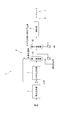
- the block diagram which shows schematic structure of the manufacturing plant of the hydrogenated petroleum resin pellet which concerns on the storage apparatus of the granular material of this invention.
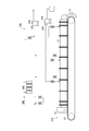
- the schematic structure figure which shows the granulation part in the manufacturing plant of the said hydrogenated petroleum resin pellet.
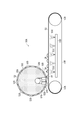
- the schematic structure figure which shows the conveyance part in the manufacturing plant of the said hydrogenated petroleum resin pellet.
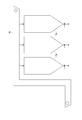
- the schematic block diagram which shows the storage part in the manufacturing plant of the said hydrogenated petroleum resin pellet.
- the perspective view which notched a part which shows the storage hopper of the said storage part.
- the front view which shows the groove-shaped inclination flow path in the said storage part.
- the side view which shows the said groove-shaped inclination flow path.
- a storage device for hydrogenated petroleum resin pellets as a storage device for a granulated product of the present invention will be described with reference to the drawings.
- a hydrogenated petroleum resin pellet is illustrated as a granular material, it can apply not only to this but to various granular materials, and the granular material which is easy to be damaged especially by an impact can be made into object.
- the structure of the manufacturing plant which manufactures the hydrogenated petroleum resin pellet provided with the storage device of the hydrogenated petroleum resin pellet is demonstrated below.
- a hydrogenated petroleum resin pellet manufacturing plant 1 is a plant for manufacturing hydrogenated petroleum resin pellets from hydrogenated petroleum resin raw materials.
- the production plant 1 includes a polymerization reaction unit 2, a hydrogenation reaction unit 3, a hydrogenation solvent recovery unit 4, a granulation unit 5, a transport unit 6, a storage unit 7, and a control unit (not shown). I have.
- the polymerization reaction unit 2 performs a polymerization reaction in which a cyclopentadiene compound and a vinyl aromatic compound are thermally polymerized to obtain a copolymer.
- the polymerization reaction unit 2 includes a polymerization reaction tank for performing a thermal polymerization reaction with a cyclopentadiene compound and a vinyl aromatic compound that are hydrogenated petroleum resin raw materials using a solvent.
- the cyclopentadiene compound include cyclopentadiene, methylcyclopentadiene, and ethylcyclopentadiene, as well as dimers and co-dimers thereof.
- Examples of vinyl aromatic compounds include styrene, ⁇ -methylstyrene, vinyltoluene and the like.
- Examples of the solvent include aromatic solvents, naphthene solvents, aliphatic hydrocarbon solvents, and the like. Specifically, benzene, toluene, xylene, cyclohexane, methylcyclohexane, dimethylcyclohexane, ethylcyclohexane and the like can be suitably used.
- the solvent is appropriately recovered from the polymerization reaction tank and reused.
- the recovered solvent usually contains a low molecular weight substance having a molecular weight of about 200 to 350.
- the concentration of the low molecular weight substance in the solvent when reused as the solvent for thermal polymerization is at least 4% by mass or less.
- the low molecular weight substance is separated and removed separately or diluted with a new solvent to obtain a low molecular weight concentration of 4% by mass or less, and at the start of the polymerization reaction. Used as a solvent for polymerization.
- the polymerization reaction tank is a reactor that performs polymerization under pressure and heating, and includes a stirrer and a heating device (not shown). Then, the first raw material tank, the second raw material tank, and the solvent tank of the solvent recovery unit are connected to the polymerization reaction tank, and the cyclopentadiene compound, the vinyl aromatic compound, and the solvent are appropriately introduced. In addition, the obtained copolymer is discharged from the bottom of the polymerization reaction tank and used for the next hydrogenation reaction.
- the amount of the polymerization solvent used is 50 to 500 parts by mass with respect to 100 parts by mass of the monomer mixture.
- the temperature of the solvent is heated to 100 ° C., preferably 150 ° C. or more at the start of thermal polymerization.
- copolymerization is performed while a mixture of a cyclopentadiene compound and a vinyl aromatic compound is added in portions in a heated solvent.
- the divided addition time is usually 0.5 to 5 hours, and it is desirable to add them equally.
- the reaction temperature is 150 ° C. or more and 350 ° C.
- the polymerization reaction tank has a softening point of 60 ° C. or higher and 130 ° C. or lower, a vinyl aromatic compound content of 30% by mass or higher and 90% by mass or lower, and a bromine value of 30 g / 100 g or higher depending on the conditions of these thermal polymerizations.
- a copolymer having 90 g / 100 g or less and a number average molecular weight of 400 to 1000 is obtained.
- the hydrogenation reaction section 3 performs a hydrogenation reaction in which hydrogen is added to the copolymer produced by thermal polymerization in the polymerization reaction section 2 to obtain a hydrogenation reaction product.
- the hydrogenation reaction section 3 includes a plurality of hydrogenation reaction towers for performing hydrogenation reaction by adding hydrogen to the copolymer produced by thermal polymerization in the polymerization reaction section 2 in the presence of a hydrogenation solvent. ing.
- the hydrogenation solvent include cyclohexane, methylcyclohexane, dimethylcyclohexane, ethylcyclohexane, tetrahydrofuran, and the like.
- the hydrogenation reaction tower is a tower filled with a hydrogenation reaction catalyst, and may be used in multiple stages.
- the hydrogenation reaction catalyst nickel, palladium, cobalt, platinum, rhodium-based catalyst or the like is used.
- the hydrogenation reaction column hydrogenates the copolymer with hydrogen in the presence of a hydrogenation reaction catalyst at a temperature of 120 to 300 ° C., a reaction pressure of 1 to 6 MPa, and a reaction time of 1 to 7 hours. .
- the softening point is 70 ° C. or more and 140 ° C.
- the vinyl aromatic compound content is 0% by mass or more and 35% by mass or less
- the bromine value is 0 g / 100 g or more and 30 g / 100 g or less
- number average A hydrogenation reaction product having a molecular weight of 400 to 1000 is obtained.
- the hydrogenation reaction section 3 after the hydrogenation reaction in the hydrogenation reaction tower, the gas phase containing unreacted hydrogen is separated and appropriately recovered and treated outside the system.
- the hydrogenation solvent recovery unit 4 separates and removes the hydrogenation solvent from the hydrogenation reaction product.
- the hydrogenated solvent recovery unit 4 includes a solvent evaporation tank 41 as a first evaporator, a thin film evaporator 42 as a second evaporator, and the like.
- the solvent evaporation tank 41 is connected to the hydrogenation reaction unit 3, and separates and recovers the hydrogenation solvent from the hydrogenation reaction product obtained in the hydrogenation reaction unit 3.
- the evaporated hydrogenated solvent is separately collected and reused as a hydrogenated solvent used in the hydrogenation reaction in the hydrogenation reaction unit 3.
- the thin film evaporator 42 is connected to the solvent evaporation tank 41 and evaporates and recovers the hydrogenated solvent remaining in the hydrogenation reaction product.
- the evaporated hydrogenated solvent and low molecular weight substance are separately collected and reused as appropriate as the hydrogenated solvent used in the hydrogenation reaction in the hydrogenation reaction section 3 in accordance with the physical properties of the hydrogenated petroleum resin pellets to be produced. Is done.
- an addition unit for adding an antioxidant is provided between the solvent evaporation tank 41 and the thin film evaporator 42 of the hydrogenated solvent recovery unit 4.
- the addition part of the antioxidant adds the antioxidant to the hydrogenation reaction product from which most of the hydrogenation solvent has been removed in the solvent evaporation tank 41.
- the solvent for dissolving the antioxidant the remaining hydrogenated solvent together with the solvent in which the antioxidant is dissolved is separated by the evaporation treatment by the thin film evaporator 42 in the subsequent stage, and the recovered hydrogenated solvent is reused for the hydrogenation reaction. can do. This is because the hydrogenation reaction is not affected.
- the solvent in which the antioxidant is dissolved is separated and recovered from the hydrogenation reaction product together with the hydrogenation solvent by the thin film evaporator 42 on the downstream side.
- the granulating unit 5 granulates the molten resin, which is a hydrogenation reaction product from which the hydrogenation solvent has been removed and the antioxidant is added, into pelletized hydrogenated petroleum resin pellets.
- the granulation unit 5 includes a granulator 50A and a granulation air cooling unit 50B as shown in FIG.
- the granulator 50A includes a granulator main body 52 and a cooling conveyor 53.
- the granulator main body 52 is disposed in the granulation casing 51 so as to face the upstream end side in the transport direction of the cooling conveyor 53.
- the granulator main body 52 has a die 52B that discharges molten resin along the axial direction from the outer peripheral surface of the body portion 52A to a body portion 52A having a cylindrical heating unit (not shown).
- the granulator main body 52 has a cylindrical rotating body 52C that fits rotatably on the outer peripheral surface of the body portion 52A.
- the rotating body 52C has a plurality of discharge holes 52D like a punching metal.
- the cooling conveyor 53 includes a pair of pulleys 53A and a metal belt 53B that is a metal endless belt that is rotatively looped around the pulleys 53A. Further, the cooling conveyor 53 is provided with a cooling section 53D that cools the metal belt 53B by ejecting cooling water 53C from the back surface of the metal belt 53B. Note that the cooling method of the metal belt 53B is not limited to the method of ejecting the cooling water 53C, and any method such as blowing cool air can be applied.
- the granulation air cooling unit 50B includes an air introduction path 54B having a blower 54A for introducing air into the granulation casing 51, and an intake blower 54C for sucking air in the granulation casing 51. And an intake passage 54E having a filter 54D.
- the air introduction path 54 ⁇ / b> B is provided so that air can be introduced into the granulation casing 51 at positions corresponding to the downstream end of the cooling conveyor 53 and the two intermediate positions.
- the intake passage 54 ⁇ / b> E is located at three positions in the vicinity of the granulator main body 52, which is the upstream end of the cooling conveyor 53, and two positions at intermediate positions in the transport direction of the cooling conveyor 53, that is, on the cooling conveyor 53.
- the intake passage 54E captures and removes the low molecular weight mist from the air containing the low molecular weight mist in the granulation casing 51 by the filter 54D and exhausts only the air.
- the intake / exhaust at the intermediate position is appropriately designed corresponding to the different softening points of the hydrogenated petroleum resin pellets to be produced. That is, it is preferable to have a structure capable of intake / exhaust at a plurality of positions so that even when the range until the molten resin solidifies varies depending on the product.
- an inertial collision filter As the filter 54D, an inertial collision filter, a blocking filter, an electrostatic adsorption filter, a brown diffusion filter, or the like is used, and a glass fiber filter is particularly preferable. That is, since the low molecular weight mist is composed of fine high-viscosity fine particles having a mist diameter of 1 ⁇ m or less, the effect of collecting particles whose mass is ignored in addition to the inertial collision effect (collection effect by Brownian diffusion) is obtained. A glass fiber filter is preferred. Further, the pressure loss of the filter 54D is preferably set to 0.5 kPa or more and 2.5 kPa or less from the relationship with the filtration area.
- a scraper 55 that scrapes off the hydrogenated petroleum resin pellets solidified on the metal belt is disposed in the granulation casing 51 at the downstream end of the cooling conveyor 53. ing. Further, the granulating casing 51 is connected to a transport unit 6 that is positioned at the downstream end of the cooling conveyor 53 and transports to the storage unit 7.
- the transport unit 6 transports the hydrogenated petroleum resin pellets granulated by the granulation unit 5 to the storage unit 7. As shown in FIG. 4, the transport unit 6 includes a chute 61 connected to the granulating unit 5, a transport conveyor 62 connected to the chute 61, and a bucket conveyor 65 (see FIG. 5). Yes.
- One end of the chute 61 is connected to the lower portion of the granulating casing 51 at the downstream end of the cooling conveyor 53 and the other end extends downward, and one end is connected to the lower end of the upper chute 61A.
- the other end has an upper chute portion 61A and a lower chute portion 61B extending to the opposite side, and is formed in a V shape in a side view.
- the upper chute portion 61A and the lower chute portion 61B are provided such that the inclined surface 63 on which the hydrogenated petroleum resin pellets flow is inclined at an inclination angle of 44 ° to 75 ° with respect to the horizontal plane.
- the hydrogenated petroleum resin pellets are retained on the inclined surface 63, and the hydrogenated petroleum resin pellets that are retained by switching the product to be manufactured are newly produced.
- the inconvenience of being mixed with the product to be produced occurs.
- the inclination angle of the inclined surface 63 is steeply greater than 75 °, the flowing speed of the hydrogenated petroleum resin pellets flowing down on the inclined surface 63 increases, and the hydrogenated petroleum resin pellets may be damaged by the falling impact. Because there is.
- the transport conveyor 62 includes a conveyor casing 62A, a belt conveyor 62B, and a recovery hopper 62C.
- the belt conveyor 62B is disposed in a conveyor casing 62A connected to the lower end of the lower chute 61B at one end, and conveys hydrogenated petroleum resin pellets flowing down the lower chute 61B.
- the belt conveyor 62B includes a pair of conveying pulleys 62B1 and an endless belt 62B2 that is looped around the conveying pulleys 62B1.
- the other end of the conveyor housing 62A is provided with a charging chute (not shown) for charging the hydrogenated petroleum resin pellets conveyed by the belt conveyor 62B into the storage unit 7.
- the charging chute is connected to a bucket conveyor that conveys hydrogenated petroleum resin pellets to the storage unit 7.
- the collection hopper 62C has an opening formed with a diameter increasing upward, and a plurality of collection hoppers 62C are provided on the lower surface of the conveyor casing 62A, positioned below the belt conveyor 62B.
- the recovery hopper 62C is formed such that the inner surface is inclined at an angle larger than the angle of repose at which the powder of the hydrogenated petroleum resin pellets collapses, specifically, 70 ° or more with respect to the horizontal plane.
- the collection hoppers 62C are not limited to a plurality of collection hoppers, and are located at least below the lower chute 61B so long as the hydrogenated petroleum resin pellets flowing down the lower chute 61B and spilling from the belt conveyor 62B can be collected. There may be only one.
- a screw conveyor (not shown) is provided below the collection hopper 62C, and the hydrogenated petroleum resin pellets and the granular materials collected in each collection hopper 62C can be conveyed outside the collection hopper 62C. Yes.
- the configuration is not limited to the configuration in which the screw conveyor is provided below the collection hopper 62C, and a configuration in which a belt conveyor or the like is provided or a discharge port that can be simply opened and closed may be provided.
- the storage unit 7 stores the hydrogenated petroleum resin pellets conveyed by the conveyance unit 6 so as to be appropriately removable. As shown in FIG. 5, the storage unit 7 includes a plurality of storage hoppers 71 and a switching unit (not shown) that inputs hydrogenated petroleum resin pellets transported by the bucket conveyor 65 of the transport unit 6 to a predetermined storage hopper 71. It is equipped with.
- the storage hopper 71 is formed, for example, with an inner peripheral surface having a cylindrical shape and a bottom portion having a reduced diameter in the vertical direction.
- a pair of openings, not shown, into which the hydrogenated petroleum resin pellets dropped from the switching unit are placed are positioned in the diametrical direction in the vicinity of the periphery.
- a discharge port that is opened and closed by a discharge valve (not shown) that discharges hydrogenated petroleum resin pellets to be stored is formed at the lower end of the storage hopper 71.
- a pair of grooved inclined channels 72 which are the channels shown in FIGS. 6 to 8, are disposed in the diameter direction of the storage hopper 71, respectively.
- the storage hopper 71 is not limited to a cylindrical shape, and can be designed in a suitable shape such as a prismatic shape.
- the grooved inclined flow path 72 flows the hydrogenated petroleum resin pellets introduced from the inlet of the storage hopper 71 obliquely downward, and suppresses the damage of the hydrogenated petroleum resin pellets.
- the groove-like inclined flow path 72 includes a support member (not shown) provided on the inner peripheral surface of the storage hopper 71 from the inlet to the bottom of the storage hopper 71, and a plurality of groove-like shapes arranged on the support member in the vertical direction. And an inclined channel member 72B.
- the support member is provided with a mounting bracket 72A1 as shown in FIG.
- the mounting bracket 72A1 is formed by bending a steel plate into an L-shaped cross section, and a plurality of mounting brackets 72A1 are provided at predetermined intervals on the inner peripheral surface of the storage hopper 71. As shown in FIGS. 7 to 9, a plurality of support members are attached in the opposite direction so that each of the plurality of vertically adjacent groove-like inclined flow path members 72B reverses the flowing direction of the hydrogenated petroleum resin pellets.
- the groove-shaped inclined flow path member 72B is a member that is formed of, for example, a stainless steel plate or the like and forms a groove-shaped structure that allows the hydrogenated petroleum resin pellets to flow obliquely downward.
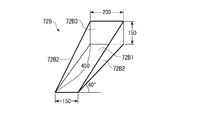
- the grooved inclined flow path member 72B is formed by bending upward on both sides of the inclined plate 72B1 and the inclined plate 72B1 inclined at an angle greater than 37 °, which is the angle of repose at which the hydrogenated petroleum resin pellets do not collapse. It has a side plate 72B2 and a plate-like member 72B3 serving as a speed reduction means that is bent upward at an end located on the upper side, which is one end of the inclined plate 72B1, to form a groove-like structure.
- the grooved inclined flow path member 72B is not limited to a stainless steel plate, and can be formed of various materials such as a surface-treated steel plate.
- the inclined plate 72B1 is formed in a trapezoidal shape that becomes gradually narrower from one end to the other end. That is, the width dimension on the lower end side is made narrow so that the hydrogenated petroleum resin pellets falling from the lower end of the inclined plate 72B1 will surely hit the plate-like member 72B3 of the groove-like inclined flow path member 72B located immediately below. .
- the width dimension of the inclined plate 72B1 may be appropriately set according to the production amount Q of hydrogenated petroleum resin pellets in the granulation unit 5.
- the height dimension H of the hydrogenated petroleum resin pellets flowing down at the lower end of the inclined plate 72B1 can be calculated.
- This height dimension H may be set to a state in which the hydrogenated petroleum resin pellets to flow down flow in a single layer without overlapping, because the hydrogenated petroleum resin pellets are in contact with each other and do not hinder the flow. preferable.
- the width dimension of the inclined plate 72B1 can be set.
- the side plate 72B2 is formed so that the height dimension decreases from one end of the inclined plate 72B1 to the other end. That is, when hydrogenated petroleum resin pellets are introduced into the storage hopper 71 and the amount of storage increases, as shown in FIG. 10, it overflows from the side plate 72B2 of the grooved inclined channel member 72B. From this, in the vicinity of the plate-like member 72B3 with which the falling hydrogenated petroleum resin pellets abut, the height is set so as not to bounce off the side plate 72B2, and the hydrogenated petroleum resin pellets are formed low on the lower end side so as to easily overflow. It is preferable. Therefore, it is preferable from the viewpoint of manufacturability to form the side plate 72B2 in a triangular shape.
- the plate-like member 72B3 reverses the flow direction of the hydrogenated petroleum resin pellets by abutting the hydrogenated petroleum resin pellets flowing down from the lower part of the other grooved inclined channel member 72B disposed above, thereby Reduce the flow rate of the resin pellets.
- This plate-like member 72B3 has a high velocity of 200 mm, which has the same potential energy, since the falling speed of the hydrogenated petroleum resin pellets charged into the storage hopper 71 is a vertical velocity from the height of 200 mm. It becomes possible to contact the hydrogenated petroleum resin pellet which falls reliably by forming in the size.
- FIG. 9 what was formed in 150 mm is illustrated.
- the plate-like member 72B3 is provided with a surface desired for the inclined plate 72B1 at an angle of ⁇ 180 °-(more than the repose angle of the hydrogenated petroleum resin pellet) ⁇ with respect to the inclined plate 72B1. That is, the groove-like inclined flow path member 72B is disposed on the inner peripheral surface of the storage hopper 71 by the support member, and the inclined plate 72B1 has a repose angle or more with respect to the horizontal plane, and the plane of the plate-like member 72B3 is It is formed in a state along the vertical direction.
- the falling speed is slower than 1.98 m / sec.
- the inclination angle is 37 ° to 45 °, preferably 40 °
- the distance from the plate-like member 72B3 to the plate-like member 72B3 of the groove-like inclined flow path member 72B located immediately below is 405 mm to 550 mm.
- it is preferably formed to 450 mm.
- each of the plurality of groove-like inclined flow path members 72B has an inclination direction of the inclined plate 72B1 in the inclination direction of another groove-like inclined flow path member 72B disposed immediately above.
- the hydrogenated petroleum resin pellets falling from the other groove-like inclined flow path member 72B arranged immediately above are arranged in a positional relationship in contact with the plate-like member 72B3. That is, each of the plurality of grooved inclined flow path members 72B is arranged under the following three preconditions. 1.
- the other is disposed immediately above and above the side plate 72B2 of the groove-shaped inclined flow path member 72B.
- the lower end of the groove-like inclined flow path member 72B is positioned, and the groove-like inclined flow path members 72B are arranged so as not to overlap each other in a side view. That is, as shown in FIG. 12, when a line with an angle of repose of 37 ° is drawn from the upper end edge of the plate-like member 72B3, other grooves arranged immediately above from the line to the groove-like inclined flow path member 72B side. It arrange
- each of the plurality of grooved inclined flow path members 72B is preferably arranged as shown in FIG.
- the plate-like member 72B3 may not be provided in the groove-like inclined channel member 72B located at the uppermost part in the groove-like inclined channel 72.
- the structure which flows a hydrogenated petroleum resin pellet diagonally downward is formed by the groove-shaped inclined flow path member 72B of the simple structure which forms a groove-shaped structure. Further, when the charged hydrogenated petroleum resin pellets are gradually accumulated and piled up to the groove-like inclined channel member 72B, as shown in FIG. 10, the grooved inclined channel member 72B overflows from the groove-like inclined channel member 72B.
- the grooved inclined flow path member 72B is configured by a grooved inclined flow path member 72B having a grooved structure that wraps around below the path member 72B. For this reason, there is no inconvenience that the hydrogenated petroleum resin pellets are clogged in the middle, and inconvenience that a dead space that cannot be stored is generated.
- the grooved inclined flow is performed with the plate-like member 72B3 positioned between the grooved inclined flow path members 72B that are arranged in the vertical direction so that the flowing direction of the hydrogenated petroleum resin pellets is opposite.
- a path 72 is formed.
- the flow direction of the hydrogenated petroleum resin pellet which flows through the groove-shaped inclination flow path member 72B diagonally downward is reversed by making it contact
- the groove width of the grooved inclined channel member 72B is formed so that the upper part is wider than the lower part, it falls from the lower part of the grooved inclined channel member 72B to form a plate shape.
- the hydrogenated petroleum resin pellets in contact with the member 72B3 can be reliably dropped onto the upper part of the other groove-like inclined flow path member 72B located immediately below without spilling down. For this reason, it is possible to prevent the hydrogenated petroleum resin pellets that have come into contact with the plate-like member 72B3 and bounced off from being spilled and damaged.
- the structure which stores the hydrogenated petroleum resin pellet which is easy to break and it is set as the structure which can prevent a breakage and can be stored favorably. For this reason, for example, when preparing a hot melt adhesive by mixing hydrogenated petroleum resin pellets with a base polymer, the hydrogenated petroleum resin pellets are broken and the particle size distribution fluctuates. The inconvenience that the setting and adjustment of the production conditions of the hot melt adhesive becomes complicated can also be prevented.
- the grooved inclined flow path member 72B is formed in a chute shape having a U-shaped cross section having the inclined plate 72B1 and the side plate 72B2, but this is not restrictive.
- hydrogenated petroleum resin pellets can flow down diagonally in any shape that forms a concave groove structure, such as one in which the inclined plate 72B1 is curved or bent in the center with a V-shaped cross section. Any shape can be used.
- the plate-shaped member 72B3 as a structure which makes the speed
- a hopper-like member that temporarily stores hydrogenated petroleum resin pellets may be used instead of the plate-like member 72B3.
- the hydrogenated petroleum resin pellets dropped from the groove-like inclined channel member 72B and received by the hopper-like member are dropped to the other groove-like inclined channel member 72B positioned below without splashing and falling down. And is swept downward in the opposite direction. For this reason, even in the configuration using the hopper-like member, it is possible to prevent the hydrogenated petroleum resin pellet from being damaged by the impact spilling from the groove-like inclined flow path member 72B, as in the above embodiment.
- the hopper-like member may be configured such that, for example, a falling hydrogenated petroleum resin pellet is brought into contact with the inner peripheral surface of the hopper-like member and dropped into the lower groove-like inclined flow path member 72B, or temporarily such as an hourglass.
- Any shape can be used as long as the hydrogenated petroleum resin pellets can be slowed down and dropped into the lower groove-shaped inclined flow path member 72B, such as a configuration that overflows and drops into the lower groove-shaped inclined flow path member 72B. Can do.
- the present invention is not limited to the plate-like member 72B3 or the hopper-like member, and any member that exhibits a speed reduction function for reducing the speed of the hydrogenated petroleum resin pellets may be used.
- the present invention is used in a storage device for storing granular materials that are easily damaged by external impacts, such as hydrogenated petroleum resin pellets.
Landscapes
- Engineering & Computer Science (AREA)
- Mechanical Engineering (AREA)
- Transportation (AREA)
- Filling Or Emptying Of Bunkers, Hoppers, And Tanks (AREA)
- Processing And Handling Of Plastics And Other Materials For Molding In General (AREA)
- Details Of Rigid Or Semi-Rigid Containers (AREA)
Abstract
Un trajet d'écoulement en pente en forme de rainure pour l'introduction en diagonale vers le bas de pastilles de résine de pétrole hydrogénée introduites à partir d'une ouverture d'introduction, est disposé à l'intérieur d'une trémie de stockage qui stocke les pastilles de résine de pétrole hydrogénée. Le trajet d'écoulement en pente en forme de rainure est configuré par la disposition, dans la direction verticale et de façon à être dans la direction opposée à la direction d'écoulement des pastilles de résine de pétrole hydrogénée, d'une pluralité d'éléments de trajet d'écoulement en pente en forme de rainure (72B) ayant une plaque inclinée (72B1) et une plaque latérale (72B2) et formant une structure en forme de rainure. Chacun des éléments de circuit de trajet d'écoulement en pente en forme de rainure (72B) adjacents verticalement est disposé dans un état qui inverse la direction suivant laquelle les pastilles de résine de pétrole hydrogénée chutant des éléments de trajet d'écoulement en pente en forme de rainure (72B) viennent en contact avec l'élément en forme de plaque (72B3) de l'élément de trajet d'écoulement en pente en forme de rainure (72B) inférieur le plus proche, et réduit la vitesse d'écoulement des pastilles de résine de pétrole hydrogénée. L'impact de la chute vers le bas sur les pastilles de résine de pétrole hydrogénée introduites à partir de l'ouverture d'introduction est réduit et un endommagement des pastilles de résine de pétrole hydrogéné durant le stockage peut être réduit.
Priority Applications (5)
| Application Number | Priority Date | Filing Date | Title |
|---|---|---|---|
| US14/116,012 US9120615B2 (en) | 2011-06-01 | 2012-05-31 | Storage device for granular material |
| CN201280022300.9A CN103502116B (zh) | 2011-06-01 | 2012-05-31 | 粒状物的贮藏装置 |
| KR1020137028900A KR101921770B1 (ko) | 2011-06-01 | 2012-05-31 | 입상물의 저장 장치 |
| SG2013081880A SG194792A1 (en) | 2011-06-01 | 2012-05-31 | Storage device for granular material |
| EP12794099.7A EP2716575A1 (fr) | 2011-06-01 | 2012-05-31 | Dispositif de stockage pour une matière granulaire |
Applications Claiming Priority (2)
| Application Number | Priority Date | Filing Date | Title |
|---|---|---|---|
| JP2011-123665 | 2011-06-01 | ||
| JP2011123665A JP5887071B2 (ja) | 2011-06-01 | 2011-06-01 | 粒状物の貯蔵装置および水添石油樹脂ペレットの貯蔵装置 |
Publications (1)
| Publication Number | Publication Date |
|---|---|
| WO2012165534A1 true WO2012165534A1 (fr) | 2012-12-06 |
Family
ID=47259386
Family Applications (1)
| Application Number | Title | Priority Date | Filing Date |
|---|---|---|---|
| PCT/JP2012/064052 WO2012165534A1 (fr) | 2011-06-01 | 2012-05-31 | Dispositif de stockage pour une matière granulaire |
Country Status (8)
| Country | Link |
|---|---|
| US (1) | US9120615B2 (fr) |
| EP (1) | EP2716575A1 (fr) |
| JP (1) | JP5887071B2 (fr) |
| KR (1) | KR101921770B1 (fr) |
| CN (1) | CN103502116B (fr) |
| SG (1) | SG194792A1 (fr) |
| TW (1) | TWI535643B (fr) |
| WO (1) | WO2012165534A1 (fr) |
Cited By (2)
| Publication number | Priority date | Publication date | Assignee | Title |
|---|---|---|---|---|
| JP2014073895A (ja) * | 2012-10-03 | 2014-04-24 | Suntory Holdings Ltd | プリフォーム供給装置 |
| JP2017024913A (ja) * | 2016-08-30 | 2017-02-02 | 静岡製機株式会社 | 穀粒品質測定器 |
Families Citing this family (3)
| Publication number | Priority date | Publication date | Assignee | Title |
|---|---|---|---|---|
| CN104773470A (zh) * | 2015-03-30 | 2015-07-15 | 宁夏众信机械设备制造有限公司 | 防撞伤缓冲装置 |
| WO2021210400A1 (fr) * | 2020-04-14 | 2021-10-21 | 出光興産株式会社 | Pastille de résine de pétrole hydrogénée et procédé de production de pastille de résine de pétrole hydrogénée |
| CN113320844B (zh) * | 2021-06-07 | 2022-09-09 | 江苏普莱克红梅色母料股份有限公司 | 一种方便取料的色母料用分类储存装置 |
Citations (12)
| Publication number | Priority date | Publication date | Assignee | Title |
|---|---|---|---|---|
| GB403146A (en) * | 1932-07-05 | 1933-12-21 | James Edward Bloomfield | Improvements in and relating to apparatus for delivering materials in bulk |
| FR1405937A (fr) * | 1964-06-02 | 1965-07-16 | Dispositif de chargement des silos | |
| JPS50152470A (fr) | 1974-05-28 | 1975-12-08 | ||
| JPS5185479U (fr) * | 1974-12-27 | 1976-07-08 | ||
| JPS5354579A (en) | 1976-10-20 | 1978-05-18 | Handoringu Kougiyou Kk | Spiral parting strip silo |
| JPS60107041U (ja) * | 1983-12-22 | 1985-07-20 | イオニ−株式会社 | 穀粒貯留タンクの緩衝装置 |
| JPH042234U (fr) * | 1990-04-17 | 1992-01-09 | ||
| JP3113554U (ja) * | 2005-02-10 | 2005-09-08 | 株式会社ユニテクノス | 簡易型緩衝シュート |
| US20060021670A1 (en) * | 2004-08-02 | 2006-02-02 | Roger Baber | Grain handling device and method of its use |
| US20070228078A1 (en) * | 2004-11-09 | 2007-10-04 | Kx Industries | Switchback shute for material handling |
| WO2010032560A1 (fr) * | 2008-09-18 | 2010-03-25 | ポリプラスチックス株式会社 | Mélange de pastilles, corps moulé et procédé de fabrication d'un corps moulé |
| JP2010179923A (ja) * | 2009-02-03 | 2010-08-19 | Sumitomo Chemical Co Ltd | 貯留容器 |
Family Cites Families (14)
| Publication number | Priority date | Publication date | Assignee | Title |
|---|---|---|---|---|
| US260104A (en) * | 1882-06-27 | lidford | ||
| US248912A (en) * | 1881-11-01 | Furnace | ||
| US3926290A (en) * | 1974-03-04 | 1975-12-16 | Mitsui Shipbuilding Eng | Loading chute for cargo vessel |
| DE2451107C2 (de) | 1974-10-28 | 1979-12-20 | Danfoss A/S, Nordborg (Daenemark) | Elektrischer Schnappschalter |
| JPS60107041A (ja) | 1983-11-15 | 1985-06-12 | Oji Paper Co Ltd | 電子写真平版印刷用原版 |
| JPH0441108Y2 (fr) * | 1988-04-15 | 1992-09-28 | ||
| JPH03113554A (ja) | 1989-09-27 | 1991-05-14 | Fujitsu Ltd | データ転送方式 |
| JPH042234A (ja) | 1990-04-19 | 1992-01-07 | Fujitsu Ltd | フレーム同期方式 |
| JP3113554B2 (ja) | 1995-09-04 | 2000-12-04 | 株式会社日本製鋼所 | 水素純度向上方法及びその装置 |
| CN1057307C (zh) * | 1997-05-16 | 2000-10-11 | 中国石油化工总公司 | 加氢石油树脂的制备方法 |
| GB9823468D0 (en) * | 1998-10-28 | 1998-12-23 | Secr Defence | Novel enzyme |
| CA2510274A1 (fr) * | 2002-12-20 | 2004-07-08 | Idemitsu Kosan Co., Ltd. | Procede de production de resine de petrole hydrogenee |
| GB2410977B (en) | 2004-02-12 | 2006-11-15 | Autoliv Dev | Improvements in or relating to a safety-belt buckle |
| CN101220124B (zh) * | 2007-12-18 | 2010-12-15 | 清华大学 | 一种脱环c5加氢树脂的生产方法 |
-
2011
- 2011-06-01 JP JP2011123665A patent/JP5887071B2/ja active Active
-
2012
- 2012-05-31 SG SG2013081880A patent/SG194792A1/en unknown
- 2012-05-31 WO PCT/JP2012/064052 patent/WO2012165534A1/fr active Application Filing
- 2012-05-31 CN CN201280022300.9A patent/CN103502116B/zh active Active
- 2012-05-31 US US14/116,012 patent/US9120615B2/en not_active Expired - Fee Related
- 2012-05-31 EP EP12794099.7A patent/EP2716575A1/fr not_active Withdrawn
- 2012-05-31 KR KR1020137028900A patent/KR101921770B1/ko active IP Right Grant
- 2012-06-01 TW TW101119754A patent/TWI535643B/zh active
Patent Citations (12)
| Publication number | Priority date | Publication date | Assignee | Title |
|---|---|---|---|---|
| GB403146A (en) * | 1932-07-05 | 1933-12-21 | James Edward Bloomfield | Improvements in and relating to apparatus for delivering materials in bulk |
| FR1405937A (fr) * | 1964-06-02 | 1965-07-16 | Dispositif de chargement des silos | |
| JPS50152470A (fr) | 1974-05-28 | 1975-12-08 | ||
| JPS5185479U (fr) * | 1974-12-27 | 1976-07-08 | ||
| JPS5354579A (en) | 1976-10-20 | 1978-05-18 | Handoringu Kougiyou Kk | Spiral parting strip silo |
| JPS60107041U (ja) * | 1983-12-22 | 1985-07-20 | イオニ−株式会社 | 穀粒貯留タンクの緩衝装置 |
| JPH042234U (fr) * | 1990-04-17 | 1992-01-09 | ||
| US20060021670A1 (en) * | 2004-08-02 | 2006-02-02 | Roger Baber | Grain handling device and method of its use |
| US20070228078A1 (en) * | 2004-11-09 | 2007-10-04 | Kx Industries | Switchback shute for material handling |
| JP3113554U (ja) * | 2005-02-10 | 2005-09-08 | 株式会社ユニテクノス | 簡易型緩衝シュート |
| WO2010032560A1 (fr) * | 2008-09-18 | 2010-03-25 | ポリプラスチックス株式会社 | Mélange de pastilles, corps moulé et procédé de fabrication d'un corps moulé |
| JP2010179923A (ja) * | 2009-02-03 | 2010-08-19 | Sumitomo Chemical Co Ltd | 貯留容器 |
Cited By (3)
| Publication number | Priority date | Publication date | Assignee | Title |
|---|---|---|---|---|
| JP2014073895A (ja) * | 2012-10-03 | 2014-04-24 | Suntory Holdings Ltd | プリフォーム供給装置 |
| JP2017024913A (ja) * | 2016-08-30 | 2017-02-02 | 静岡製機株式会社 | 穀粒品質測定器 |
| JP7019126B2 (ja) | 2016-08-30 | 2022-02-15 | 静岡製機株式会社 | 穀粒品質測定器 |
Also Published As
| Publication number | Publication date |
|---|---|
| CN103502116B (zh) | 2016-04-13 |
| TW201309571A (zh) | 2013-03-01 |
| JP2012250730A (ja) | 2012-12-20 |
| KR20140022047A (ko) | 2014-02-21 |
| TWI535643B (zh) | 2016-06-01 |
| US20140093340A1 (en) | 2014-04-03 |
| CN103502116A (zh) | 2014-01-08 |
| SG194792A1 (en) | 2013-12-30 |
| US9120615B2 (en) | 2015-09-01 |
| EP2716575A1 (fr) | 2014-04-09 |
| KR101921770B1 (ko) | 2018-11-23 |
| JP5887071B2 (ja) | 2016-03-16 |
Similar Documents
| Publication | Publication Date | Title |
|---|---|---|
| JP5840870B2 (ja) | 水添石油樹脂ペレットの搬送装置、および、水添石油樹脂ペレットの製造プラント | |
| WO2012165534A1 (fr) | Dispositif de stockage pour une matière granulaire | |
| JP5709647B2 (ja) | 粉粒物の搬送装置、粉粒物の製造プラント、および、粉粒物の搬送方法 | |
| JPH02501921A (ja) | 粒状ビスフェノールの製造 | |
| JP2023032091A (ja) | 粒鉄製造装置および粒鉄製造方法 | |
| JP3325880B2 (ja) | セメントクリンカ焼成方法及び焼成装置 | |
| JP2002306943A (ja) | 向流式造粒装置 | |
| JPH0437354B2 (fr) | ||
| JP2012192388A (ja) | 振動式ガスハイドレートペレット分離器 | |
| JPH0428434B2 (fr) | ||
| JP2001328723A (ja) | コンベア乗り継ぎ部構造 |
Legal Events
| Date | Code | Title | Description |
|---|---|---|---|
| 121 | Ep: the epo has been informed by wipo that ep was designated in this application |
Ref document number: 12794099 Country of ref document: EP Kind code of ref document: A1 |
|
| ENP | Entry into the national phase |
Ref document number: 20137028900 Country of ref document: KR Kind code of ref document: A |
|
| WWE | Wipo information: entry into national phase |
Ref document number: 14116012 Country of ref document: US |
|
| NENP | Non-entry into the national phase |
Ref country code: DE |