WO2012165232A1 - ピストン組立体、流体圧シリンダ及びピストン組立体の製造方法 - Google Patents
ピストン組立体、流体圧シリンダ及びピストン組立体の製造方法 Download PDFInfo
- Publication number
- WO2012165232A1 WO2012165232A1 PCT/JP2012/063083 JP2012063083W WO2012165232A1 WO 2012165232 A1 WO2012165232 A1 WO 2012165232A1 JP 2012063083 W JP2012063083 W JP 2012063083W WO 2012165232 A1 WO2012165232 A1 WO 2012165232A1
- Authority
- WO
- WIPO (PCT)
- Prior art keywords
- piston
- piston member
- assembly
- joined
- rod
- Prior art date
- Legal status (The legal status is an assumption and is not a legal conclusion. Google has not performed a legal analysis and makes no representation as to the accuracy of the status listed.)
- Ceased
Links
Images


Classifications
-
- F—MECHANICAL ENGINEERING; LIGHTING; HEATING; WEAPONS; BLASTING
- F15—FLUID-PRESSURE ACTUATORS; HYDRAULICS OR PNEUMATICS IN GENERAL
- F15B—SYSTEMS ACTING BY MEANS OF FLUIDS IN GENERAL; FLUID-PRESSURE ACTUATORS, e.g. SERVOMOTORS; DETAILS OF FLUID-PRESSURE SYSTEMS, NOT OTHERWISE PROVIDED FOR
- F15B15/00—Fluid-actuated devices for displacing a member from one position to another; Gearing associated therewith
- F15B15/08—Characterised by the construction of the motor unit
- F15B15/14—Characterised by the construction of the motor unit of the straight-cylinder type
- F15B15/1423—Component parts; Constructional details
- F15B15/1447—Pistons; Piston to piston rod assemblies
-
- F—MECHANICAL ENGINEERING; LIGHTING; HEATING; WEAPONS; BLASTING
- F15—FLUID-PRESSURE ACTUATORS; HYDRAULICS OR PNEUMATICS IN GENERAL
- F15B—SYSTEMS ACTING BY MEANS OF FLUIDS IN GENERAL; FLUID-PRESSURE ACTUATORS, e.g. SERVOMOTORS; DETAILS OF FLUID-PRESSURE SYSTEMS, NOT OTHERWISE PROVIDED FOR
- F15B15/00—Fluid-actuated devices for displacing a member from one position to another; Gearing associated therewith
- F15B15/08—Characterised by the construction of the motor unit
- F15B15/14—Characterised by the construction of the motor unit of the straight-cylinder type
-
- B—PERFORMING OPERATIONS; TRANSPORTING
- B23—MACHINE TOOLS; METAL-WORKING NOT OTHERWISE PROVIDED FOR
- B23K—SOLDERING OR UNSOLDERING; WELDING; CLADDING OR PLATING BY SOLDERING OR WELDING; CUTTING BY APPLYING HEAT LOCALLY, e.g. FLAME CUTTING; WORKING BY LASER BEAM
- B23K11/00—Resistance welding; Severing by resistance heating
- B23K11/002—Resistance welding; Severing by resistance heating specially adapted for particular articles or work
- B23K11/004—Welding of a small piece to a great or broad piece
- B23K11/0046—Welding of a small piece to a great or broad piece the extremity of a small piece being welded to a base, e.g. cooling studs or fins to tubes or plates
- B23K11/006—Welding a tip to a base, e.g. pen point nibs
-
- B—PERFORMING OPERATIONS; TRANSPORTING
- B23—MACHINE TOOLS; METAL-WORKING NOT OTHERWISE PROVIDED FOR
- B23K—SOLDERING OR UNSOLDERING; WELDING; CLADDING OR PLATING BY SOLDERING OR WELDING; CUTTING BY APPLYING HEAT LOCALLY, e.g. FLAME CUTTING; WORKING BY LASER BEAM
- B23K11/00—Resistance welding; Severing by resistance heating
- B23K11/14—Projection welding
-
- B—PERFORMING OPERATIONS; TRANSPORTING
- B23—MACHINE TOOLS; METAL-WORKING NOT OTHERWISE PROVIDED FOR
- B23K—SOLDERING OR UNSOLDERING; WELDING; CLADDING OR PLATING BY SOLDERING OR WELDING; CUTTING BY APPLYING HEAT LOCALLY, e.g. FLAME CUTTING; WORKING BY LASER BEAM
- B23K11/00—Resistance welding; Severing by resistance heating
- B23K11/16—Resistance welding; Severing by resistance heating taking account of the properties of the material to be welded
- B23K11/18—Resistance welding; Severing by resistance heating taking account of the properties of the material to be welded of non-ferrous metals
- B23K11/185—Resistance welding; Severing by resistance heating taking account of the properties of the material to be welded of non-ferrous metals of aluminium or aluminium alloys
-
- F—MECHANICAL ENGINEERING; LIGHTING; HEATING; WEAPONS; BLASTING
- F15—FLUID-PRESSURE ACTUATORS; HYDRAULICS OR PNEUMATICS IN GENERAL
- F15B—SYSTEMS ACTING BY MEANS OF FLUIDS IN GENERAL; FLUID-PRESSURE ACTUATORS, e.g. SERVOMOTORS; DETAILS OF FLUID-PRESSURE SYSTEMS, NOT OTHERWISE PROVIDED FOR
- F15B15/00—Fluid-actuated devices for displacing a member from one position to another; Gearing associated therewith
- F15B15/20—Other details, e.g. assembly with regulating devices
- F15B15/28—Means for indicating the position, e.g. end of stroke
-
- F—MECHANICAL ENGINEERING; LIGHTING; HEATING; WEAPONS; BLASTING
- F16—ENGINEERING ELEMENTS AND UNITS; GENERAL MEASURES FOR PRODUCING AND MAINTAINING EFFECTIVE FUNCTIONING OF MACHINES OR INSTALLATIONS; THERMAL INSULATION IN GENERAL
- F16J—PISTONS; CYLINDERS; SEALINGS
- F16J1/00—Pistons; Trunk pistons; Plungers
- F16J1/005—Pistons; Trunk pistons; Plungers obtained by assembling several pieces
- F16J1/006—Pistons; Trunk pistons; Plungers obtained by assembling several pieces of different materials
- F16J1/008—Pistons; Trunk pistons; Plungers obtained by assembling several pieces of different materials with sealing lips
-
- F—MECHANICAL ENGINEERING; LIGHTING; HEATING; WEAPONS; BLASTING
- F16—ENGINEERING ELEMENTS AND UNITS; GENERAL MEASURES FOR PRODUCING AND MAINTAINING EFFECTIVE FUNCTIONING OF MACHINES OR INSTALLATIONS; THERMAL INSULATION IN GENERAL
- F16J—PISTONS; CYLINDERS; SEALINGS
- F16J1/00—Pistons; Trunk pistons; Plungers
- F16J1/10—Connection to driving members
- F16J1/12—Connection to driving members with piston-rods, e.g. rigid connections
-
- B—PERFORMING OPERATIONS; TRANSPORTING
- B23—MACHINE TOOLS; METAL-WORKING NOT OTHERWISE PROVIDED FOR
- B23K—SOLDERING OR UNSOLDERING; WELDING; CLADDING OR PLATING BY SOLDERING OR WELDING; CUTTING BY APPLYING HEAT LOCALLY, e.g. FLAME CUTTING; WORKING BY LASER BEAM
- B23K2101/00—Articles made by soldering, welding or cutting
- B23K2101/003—Pistons
-
- B—PERFORMING OPERATIONS; TRANSPORTING
- B23—MACHINE TOOLS; METAL-WORKING NOT OTHERWISE PROVIDED FOR
- B23K—SOLDERING OR UNSOLDERING; WELDING; CLADDING OR PLATING BY SOLDERING OR WELDING; CUTTING BY APPLYING HEAT LOCALLY, e.g. FLAME CUTTING; WORKING BY LASER BEAM
- B23K2103/00—Materials to be soldered, welded or cut
- B23K2103/02—Iron or ferrous alloys
- B23K2103/04—Steel or steel alloys
- B23K2103/05—Stainless steel
-
- B—PERFORMING OPERATIONS; TRANSPORTING
- B23—MACHINE TOOLS; METAL-WORKING NOT OTHERWISE PROVIDED FOR
- B23K—SOLDERING OR UNSOLDERING; WELDING; CLADDING OR PLATING BY SOLDERING OR WELDING; CUTTING BY APPLYING HEAT LOCALLY, e.g. FLAME CUTTING; WORKING BY LASER BEAM
- B23K2103/00—Materials to be soldered, welded or cut
- B23K2103/08—Non-ferrous metals or alloys
- B23K2103/10—Aluminium or alloys thereof
-
- F—MECHANICAL ENGINEERING; LIGHTING; HEATING; WEAPONS; BLASTING
- F15—FLUID-PRESSURE ACTUATORS; HYDRAULICS OR PNEUMATICS IN GENERAL
- F15B—SYSTEMS ACTING BY MEANS OF FLUIDS IN GENERAL; FLUID-PRESSURE ACTUATORS, e.g. SERVOMOTORS; DETAILS OF FLUID-PRESSURE SYSTEMS, NOT OTHERWISE PROVIDED FOR
- F15B15/00—Fluid-actuated devices for displacing a member from one position to another; Gearing associated therewith
- F15B15/20—Other details, e.g. assembly with regulating devices
- F15B15/28—Means for indicating the position, e.g. end of stroke
- F15B15/2807—Position switches, i.e. means for sensing of discrete positions only, e.g. limit switches
Definitions
- the present invention relates to a piston assembly having a piston body and a piston rod coupled to the piston body, a fluid pressure cylinder having the piston assembly, and a method of manufacturing the piston assembly.
- the fluid pressure cylinder has a cylinder, a piston arranged in the cylinder so as to be movable in the axial direction, and a piston rod connected to the piston, and is connected to the piston by displacing the piston by fluid pressure.
- the piston rod is moved.
- a screwing method or a caulking method is generally employed as a method for coupling the piston and the piston rod.
- a screw hole female screw
- a caulking method is generally employed.
- a screw hole (female screw) penetrating the piston in the axial direction is provided, a male screw is provided at one end of the piston rod, and the piston rod is screwed directly into the piston and fastened, or a drill hole is provided in the piston.
- the piston rod is connected to the piston rod by inserting one end of the piston rod into a hole in the piston and fastening with a nut or the like (see, for example, Japanese Utility Model Publication No. 58-123957 (FIG. 10)).
- the piston is provided with an axial through hole, and the piston rod is inserted into the through hole and then part of the piston is plastically deformed to couple the piston and the piston rod (for example, Japanese Utility Model Sho 63). No. -4406 (see FIG. 1)).
- the plastic plastic deformation may provide a sealing function. In this case, however, a sufficient sealing function may not be obtained.
- the present invention has been made in consideration of such problems, and it is not necessary to provide a seal member between the piston and the piston rod, and a piston assembly and a fluid pressure cylinder that can shorten the overall length of the product. And it aims at providing the manufacturing method of a piston assembly.
- the present invention includes a piston main body and a piston rod joined to the piston main body, and the piston main body includes a first piston member and a second piston constituted by plate-like members.
- the first piston member and the second piston member are joined to each other in a state where they are overlapped in the axial direction of the piston rod, and the outer peripheral edge of the first piston member and the first piston member A seal mounting groove extending in the circumferential direction is formed between the outer peripheral edge of the two piston members, and at least one of the first piston member and the second piston member has a plate thickness throughout.
- the piston body is constituted by the first piston member and the second piston member made of plate-like members, the piston width (thickness in the axial direction) can be shortened.
- the overall length of the fluid pressure cylinder in which the solid body is incorporated can be shortened, and the cost can be reduced.
- a sealing member between the piston body and the piston rod is essentially unnecessary, and the number of parts can be reduced by eliminating such a sealing member. it can.
- the seal member is unnecessary, there is no need to provide a seal groove for mounting it, and the configuration can be simplified. Further, unlike the configuration in which the sealing function is provided by plastic deformation such as caulking, the reliability problem of the sealing function can be fundamentally avoided.
- the first piston member is provided with a through hole in the plate thickness direction, and one end of the piston rod is formed with a fitting portion that fits into the through hole. Good.
- a piston main part is fitted by fitting the fitting part provided in the end of the piston rod in the through-hole provided in the 1st piston member.
- the piston rod can be easily positioned with high accuracy.
- the piston main body includes a third piston member constituted by a plate-like member, and is disposed between the second piston member and the third piston member at an outer peripheral portion of the piston main body.
- a support member or a magnet extending along the outer periphery of the piston member may be disposed in the formed groove.
- the overall length of the cylinder can be shortened by shortening the width of the piston body, and the entire device can be downsized, Cost can be reduced.
- first piston member and the second piston member may be joined by welding, and the piston main body and the piston rod may be joined by welding.
- the first piston member and the second piston member can be reliably joined without providing a hole penetrating in the plate thickness direction in the first piston member or the second piston member.
- a fluid pressure cylinder includes the above-described piston assembly and a housing that accommodates the piston assembly so as to be movable in the axial direction.
- the total length of the piston assembly can be shortened, the total length of the fluid pressure cylinder can be shortened.
- the manufacturing method of the piston assembly according to the present invention includes a first step in which a first piston member and a second piston member constituted by plate-like members are overlapped and joined together to obtain a piston main body, A second step of joining the piston body and the piston rod, and a seal mounting groove extending in a circumferential direction between an outer peripheral edge portion of the first piston member and an outer peripheral edge portion of the second piston member And at least one of the first piston member and the second piston member has a plate thickness throughout.
- the piston width (thickness in the axial direction) can be shortened, and the seal member between the piston body and the piston rod can be omitted, so that the number of parts can be reduced and the seal groove for mounting the seal member
- the configuration can be simplified by eliminating the need for.
- first piston member and the second piston member may be joined by welding
- piston body and the piston rod may be joined by welding
- the first piston member and the second piston member can be reliably joined without providing a hole penetrating in the plate thickness direction in the first piston member or the second piston member.
- the manufacturing method of the piston assembly, fluid pressure cylinder, and piston assembly of the present invention it is not necessary to provide a seal member between the piston body and the piston rod, and the overall length of the cylinder device can be shortened. Alternatively, if it is incorporated into a cylinder device having the same length as the conventional one, an effect of extending the stroke can be obtained.
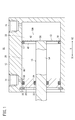
- FIG. 1 is a partially omitted vertical cross-sectional view along the axial direction of a fluid pressure cylinder including a piston assembly according to a first embodiment of the present invention.
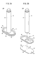
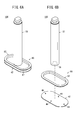
- 2A is a perspective view of the piston assembly shown in FIG. 1
- FIG. 2B is an exploded perspective view of the piston assembly shown in FIG.
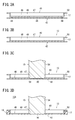
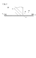
- FIG. 3A is a longitudinal sectional view before welding of the first piston member and the second piston member
- FIG. 3B is a longitudinal sectional view after welding of the first piston member and the second piston member
- FIG. FIG. 3D is a longitudinal sectional view before welding of the piston body and the piston rod
- FIG. 3D is a longitudinal sectional view after welding of the piston body and the piston rod.
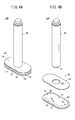
- FIG. 4A is a perspective view of a piston assembly according to a second embodiment of the present invention
- FIG. 4B is an exploded perspective view of the piston assembly shown in FIG. 4A
- FIG. 5 is a longitudinal sectional view of the piston assembly shown in FIG. 4A with the seal member attached
- 6A is a perspective view of a piston assembly according to a third embodiment of the present invention
- FIG. 6B is an exploded perspective view of the piston assembly shown in FIG. 6A.
- FIG. 7 is a vertical cross-sectional view of the piston assembly shown in FIG. 6A with the seal member attached.
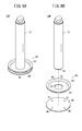
- 8A is a perspective view of a piston assembly according to a fourth embodiment of the present invention
- FIG. 8B is an exploded perspective view of the piston assembly shown in FIG. 8A.
- FIG. 8A is a perspective view of a piston assembly according to a fourth embodiment of the present invention
- FIG. 8B is an exploded perspective view of the piston assembly shown in FIG. 8A.
- FIG. 8A is
- FIG. 9 is a longitudinal sectional view of the piston assembly shown in FIG. 8A with the seal member attached.
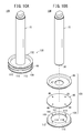
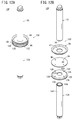
- FIG. 10A is a perspective view of a piston assembly according to a fifth embodiment of the present invention, and FIG. 10B is an exploded perspective view of the piston assembly shown in FIG. 10A.
- FIG. 11 is a longitudinal sectional view of the piston assembly shown in FIG. 10A with the seal member and the wear ring attached thereto.
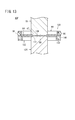
- 12A is a perspective view of a piston assembly according to a sixth embodiment of the present invention, and FIG. 12B is an exploded perspective view of the piston assembly shown in FIG. 12A.
- FIG. 13 is a longitudinal sectional view of the piston assembly shown in FIG. 12A with a seal member and a magnet attached thereto.
- FIG. 1 is a partially omitted longitudinal sectional view along the axial direction of a fluid pressure cylinder 11 provided with a piston assembly 10A according to a first embodiment of the present invention.
- the fluid pressure cylinder 11 includes, as basic components, a housing (cylinder main body) 12, a piston main body 13 disposed in the housing 12 so as to be movable in the axial direction, and a piston rod 15 connected to the piston main body 13.
- the piston rod 15 connected to the piston body 13 is moved forward and backward by moving the piston body 13 in the axial direction within the housing 12 by the action of fluid pressure.
- the housing 12 is made of a metal material such as an aluminum alloy and includes a pair of ports 14 and 16, and a sliding hole (cylinder chamber) 18 communicating with the ports 14 and 16 is provided therein.
- the piston body 13 is disposed inside the sliding hole 18 so as to be reciprocally movable in the axial direction within a restricted range.
- the piston body 13 is accommodated in the housing 12 and is partitioned into a pressure chamber 20 on one port 14 side and a pressure chamber 22 on the other port 16 side, and the axial direction of the sliding hole 18 (in FIG. 1). , An arrow X direction).
- a seal mounting groove 17 is formed extending along the outer periphery of the piston body 13.
- a seal member (piston packing) 19 made of an elastic material (for example, a rubber material) is mounted in the seal mounting groove 17.
- the seal member 19 protrudes outward from the outermost peripheral portion of the piston body 13 and circulates around the piston body 13.
- the seal member 19 is an O-ring made of an elastic body such as synthetic rubber.
- the seal member 19 seals the outer peripheral surface of the piston body 13 and the inner peripheral surface of the sliding hole 18, and the two pressure chambers 20 and 22 are partitioned in an airtight (or liquid tight) manner.
- the base end portion (end portion on the X2 direction side) of the piston rod 15 is connected to the piston body 13, and the tip end portion (end portion on the X1 direction side) of the piston rod 15 is a rod that blocks the end portion of the sliding hole 18. It extends through the cover 30 to the outside of the sliding hole 18.
- the piston main body 13 and the piston rod 15 constitute a piston assembly 10A.
- a seal member 34 made of an elastic material that seals between the inner peripheral surface of the rod cover 30 and the outer peripheral surface of the piston rod 15 is attached to the annular groove 32 formed in the inner peripheral portion of the rod cover 30.
- a seal member 38 made of an elastic material that seals between the outer peripheral surface of the rod cover 30 and the inner peripheral surface of the sliding hole 18 is attached to the annular groove 36 formed in the outer peripheral portion of the rod cover 30.
- FIG. 2A is a perspective view of the piston assembly 10A shown in FIG. 1
- FIG. 2B is a perspective view of components before assembly (before joining) of the piston assembly 10A shown in FIG.
- the piston main body 13 described above is composed of a first piston member 40 and a second piston member 42. That is, the piston assembly 10 ⁇ / b> A includes the first piston member 40, the second piston member 42, and the piston rod 15.
- Each of the first piston member 40 and the second piston member 42 is a plate member having an oval shape as a whole formed by plastic processing (for example, pressing) a metal plate, and is joined to each other by welding. Yes. As will be described later, in the present embodiment, the first piston member 40 and the second piston member 42 are joined by projection welding.
- the first piston member 40 includes a flat oval base 46, a side peripheral wall 48 extending in the axial direction from the entire periphery of the periphery of the base 46, and an end of the side peripheral wall 48 (the tip of the piston rod 15 A flange portion 50 that spreads outward from the end portion on the side.
- a circular through hole 47 is formed in the center of the base 46 in the thickness direction.
- the second piston member 42 has an oval shape as a whole as a flat plate, and is joined to the first piston member 40 before welding the first piston member 40 and the second piston member 42 as shown in FIG. 2B.
- a plurality of (four in the illustrated example) welding projections (first welding projections) 44 are provided on the surface on the side to be processed.
- the second piston member 42 has a predetermined plate thickness over its entirety, and is not provided with a hole penetrating in the plate thickness direction.
- the shape and size of the contour of the flange portion 50 of the first piston member 40 and the shape and size of the contour of the second piston member 42 are substantially the same.
- the seal mounting groove 17 extends in the circumferential direction between the outer peripheral edge of the first piston member 40 and the outer peripheral edge of the second piston member 42. That is, the seal mounting groove 17 extends in the same oval shape as the piston main body 13 (the first piston member 40 and the second piston member 42).
- the piston rod 15 in the illustrated example has a cylindrical body portion 54, and a circular fitting portion 56 that protrudes concentrically with the body portion 54 is formed at the base end of the body portion 54 (FIG. 3C). And also see FIG. 3D).
- the fitting portion 56 has an outer diameter smaller than that of the body portion 54 of the piston rod 15, and the outer diameter is the same as or slightly smaller than the inner diameter of the through hole 47 provided in the first piston member 40.
- a circular step is formed by the difference in outer diameter between the body portion 54 and the fitting portion 56.
- the piston rod 15 before the piston rod 15 and the piston body 13 are welded further has a welding projection (second welding projection) 58 formed to project from the vicinity of the peripheral edge of the fitting portion 56 in the proximal direction. is doing.
- the welding projection 58 in the illustrated example is formed in a circular ring shape, but may be configured as a plurality of dot-like or linear projections.
- the constituent material of the first piston member 40, the second piston member 42, and the piston rod 15 is not particularly limited as long as it is a material (metal) that can be welded and can ensure the necessary strength. Stainless steel, aluminum, aluminum alloy, etc. can be used.
- the first piston member 40, the second piston member 42, and the piston rod 15 formed in the shape shown in FIG. 2B are prepared.
- the first piston member 40 and the second piston member 42 are joined to each other by projection welding.
- both members are energized in a state where the first piston member 40 and the second piston member 42 are pressed concentrically and pressurized.
- the welding projections 44 provided on the second piston member 42 are melted by resistance heating, so that the first piston member 40 and the second piston member 42 are joined to each other as shown in FIG. 3B.
- the piston main body 13 which consists of the 1st piston member 40 and the 2nd piston member 42 is manufactured.
- first piston member 40 and the second piston member 42 may be joined and integrated with each other without providing the welding projection 44 on the second piston member 42.
- the piston body 13 and the piston rod 15 are joined to each other by projection welding.
- the piston rod 15 is butted against the piston body 13. That is, the fitting portion 56 provided at the proximal end of the piston rod 15 is fitted into the through hole 47 provided in the first piston member 40. Thereby, positioning of the piston rod 15 with respect to the piston main body 13 can be performed easily and accurately.
- the welding projection 58 provided on the piston rod 15 contacts the second piston member 42.
- both the piston rod 15 and the piston body 13 are energized while being pressurized in the axial direction. Then, the welding projection 58 provided on the piston rod 15 is melted by resistance heating, so that the piston body 13 (second piston member 42) and the piston rod 15 are joined to each other as shown in FIG. 3D. Thereby, the piston assembly 10 ⁇ / b> A including the first piston member 40, the second piston member 42, and the piston rod 15 is obtained.
- a seal member 19 is mounted on the outer peripheral portion (seal mounting groove 17) of the piston main body 13 of the piston assembly 10A manufactured as described above, and is slidably disposed in the housing 12 as shown in FIG. Then, the fluid pressure cylinder 11 is assembled.
- piston rod 15 and the piston body 13 may be joined and integrated by an adhesive without providing the welding projection 58 on the piston rod 15.
- the fluid pressure cylinder 11 including the piston assembly 10A according to the present embodiment is basically configured as described above, and the operation and effect thereof will be described below.
- the piston main body 13 is constituted by the first piston member 40 and the second piston member 42 made of plate-like members, and thus has a considerable thickness obtained by cutting or forging as in the past.
- the width (thickness in the axial direction) of the piston main body 13 can be shortened, and accordingly, the total length of the fluid pressure cylinder 11 in which the piston assembly 10A is incorporated can be shortened, thereby reducing the cost. it can.
- the stroke of the piston body 13 can be increased by reducing the width (length in the axial direction) of the piston body 13. That is, the stroke can be lengthened without increasing the size of the apparatus.
- the first piston member 40 is provided with a through hole 47, but the second piston member 42 is not provided with a hole penetrating in the plate thickness direction. There are no through-holes.
- a seal member between the piston body 13 and the piston rod 15 is essentially unnecessary, and such a seal member can be omitted.
- the number of parts can be reduced.
- such a sealing member is unnecessary, it is not necessary to provide the sealing groove
- the first piston member 40 is provided with a through hole 47 in the plate thickness direction, and a fitting portion 56 that fits into the through hole 47 is provided at one end of the piston rod 15. Protrusions are formed. Therefore, when the piston body 13 and the piston rod 15 are welded, the fitting portion 56 provided at one end of the piston rod 15 is fitted into the through hole 47 provided in the first piston member 40, whereby the piston Positioning of the piston rod 15 with respect to the main body 13 can be easily performed with high accuracy.
- piston assembly 10B according to the second embodiment will be described with reference to FIGS. 4A to 5.
- elements having the same or similar functions and effects as those of the piston assembly 10A according to the first embodiment are denoted by the same reference numerals, and detailed description thereof is omitted. To do.
- the piston assembly 10B includes a piston body 60 having a configuration different from that of the piston body 13 shown in FIG.
- the piston body 60 includes a first piston member 62 and a second piston member 64.
- Each of the first piston member 62 and the second piston member 64 is a plate-like member having an oval shape as a whole formed by plastic processing (for example, pressing) a metal plate, and is joined to each other by welding. Yes. As will be described later, in the present embodiment, the first piston member 62 and the second piston member 64 are joined by projection welding.
- the first piston member 62 as a whole has an oval shape and a substantially flat plate shape, and as shown in FIG. 4B, a circular through hole 66 is formed through the center in the thickness direction.
- the inner diameter of the through hole 66 is the same as or slightly larger than the outer diameter of the fitting portion 56 of the piston rod 15.
- the second piston member 64 includes a flat oval base 68, a side peripheral wall 70 extending in the axial direction from the entire circumference of the periphery of the base 68, and an end of the side peripheral wall 70 (the piston rod 15 is The opposite end) or a flange 72 extending outward over the entire circumference.
- a plurality of (four in the illustrated example) welding projections 74 are provided on the surface to be joined to the first piston member 62.
- the second piston member 64 has a predetermined plate thickness over its entirety, and no hole penetrating in the plate thickness direction is provided.
- the shape and size of the contour of the first piston member 62 and the shape and size of the contour of the flange portion 72 of the second piston member 64 are substantially the same.
- the seal mounting groove 65 extends in the circumferential direction between the outer peripheral edge of the first piston member 62 and the outer peripheral edge of the second piston member 64. That is, the seal mounting groove 65 extends in the same oval shape as the piston main body 60 (the first piston member 62 and the second piston member 64).
- the piston assembly 10B In order to manufacture the piston assembly 10B, as in the piston assembly 10A according to the first embodiment described above, first, the first piston member 62 and the second piston member 64 are joined by projection welding, and then, The piston main body 60 and the piston rod 15 are joined by projection welding. Thereby, as shown in FIGS. 4A and 5, the piston assembly 10 ⁇ / b> B including the first piston member 62, the second piston member 64, and the piston rod 15 is obtained.
- first piston member 62 and the second piston member 64 may be joined and integrated with each other without providing the welding projection 74 on the second piston member 64.
- piston rod 15 and the piston main body 60 may be joined and integrated by an adhesive without providing the welding projection 58 on the piston rod 15.
- the seal member 19 is mounted on the outer peripheral portion (seal mounting groove 65) of the piston main body 60 of the piston assembly 10B thus manufactured, and is slidably disposed in the housing 12 (see FIG. 1).
- the fluid pressure cylinder 11 is assembled.
- FIG. 10C according to the third embodiment elements having the same or similar functions and effects as those of the piston assembly 10A according to the first embodiment are denoted by the same reference numerals, and detailed description thereof is omitted. To do.
- the piston assembly 10C includes a piston body 80 and a piston rod 81 connected to the piston body 80.
- the piston rod 81 has a configuration in which the fitting portion 56 is eliminated from the piston rod 15 shown in FIG.
- a welding projection 58 similar to the welding projection 58 shown in FIG. 3C is provided on the proximal end surface of the piston rod 81.
- the piston main body 80 includes a first piston member 82 and a second piston member 42.
- the 1st piston member 82 is the structure which eliminated the through-hole 47 from the 1st piston member 40 shown to FIG. 2B etc. That is, in the third embodiment, the first piston member 82 is not provided with a hole penetrating in the plate thickness direction, and is formed of a flat plate having a predetermined plate thickness as a whole.
- the second piston member 42 has the same configuration as the second piston member 42 shown in FIGS. 2A and 2B.
- the first piston member 82 and the second piston member 42 are joined by projection welding in the same manner as the piston assembly 10A according to the first embodiment described above.
- the piston body 80 and the piston rod 81 are joined by projection welding.
- the base end of the piston rod 81 is abutted against the central portion of the first piston member 82, and the piston rod 81 and the piston main body 80 are energized in the axial direction.
- the welding projection 58 provided on the piston rod 81 is melted by resistance heating, so that the piston main body 80 (first piston member 82) and the piston rod 81 are joined to each other as shown in FIG. .
- the piston assembly 10 ⁇ / b> C including the first piston member 82, the second piston member 42, and the piston rod 81 is obtained.
- first piston member 82 and the second piston member 42 may be joined and integrated with each other without providing the welding projection 44 on the second piston member 42.
- piston rod 81 and the piston main body 80 may be joined and integrated with an adhesive without providing the welding projection 58 on the piston rod 81.
- a seal member 19 is mounted on the outer peripheral portion (seal mounting groove 17) of the piston main body 80 of the piston assembly 10C thus manufactured, and is slidably disposed in the housing 12 (see FIG. 1).
- the fluid pressure cylinder 11 is assembled.
- the piston main body 88 including the first piston member 84 and the second piston member 86 may be configured in a circular shape.
- the piston main body 88 (the first piston member 84 and the second piston member 86) is the same as the piston main body 13 shown in FIG. 2B (the first piston member 40 and the second piston member 42) except that the overall shape is circular. It has the same composition as.
- the first piston member 84 includes a flat circular base 90, a cylindrical side peripheral wall 92 extending in the axial direction from the entire periphery of the periphery of the base 90, and an end of the side peripheral wall 92 (piston A flange portion 94 that spreads outward in the radial direction over the entire circumference from the end portion on the tip end side of the rod 15.
- a circular through hole 47 is formed in the center of the base 90 in the thickness direction.
- the second piston member 86 has a generally circular flat plate shape as a whole, and is joined to the first piston member 84 before welding the first piston member 84 and the second piston member 86, as shown in FIG. 8B.
- a plurality of (four in the illustrated example) welding projections (first welding projections) 44 are provided on the surface on the side to be processed.
- the second piston member 86 has a predetermined plate thickness throughout, and is not provided with a hole penetrating in the plate thickness direction.
- the outer diameters of the first piston member 84 and the second piston member 86 are substantially the same.
- An annular seal mounting groove 96 extending in the circumferential direction is formed by the flange portion 94 of the first piston member 84, the side peripheral wall portion 92, and the outer peripheral edge portion of the second piston member 86.
- the piston assembly 10D can be assembled in the same procedure as that for assembling the piston assembly 10A according to the first embodiment.
- a ring-shaped seal member 98 made of an elastic material is mounted on the outer peripheral portion (seal mounting groove 96) of the piston main body 88 of the piston assembly 10D.
- the piston assembly 10D to which the seal member 98 is attached is slidably disposed in a housing having a sliding hole with a circular cross section, and is assembled as a fluid pressure cylinder.
- FIGS. 10A to 11 a piston assembly 10E according to a fifth embodiment will be described with reference to FIGS. 10A to 11.
- the piston assembly 10E according to the fifth embodiment is different from the piston assembly 10D according to the fourth embodiment with respect to the configuration of the piston body 100.
- the piston main body 100 includes a first piston member 84, a second piston member 86, and a third piston member 106.
- the first piston member 84 and the second piston member 86 are configured the same as the first piston member 84 and the second piston member 86 shown in FIGS. 8A and 8B, respectively.
- the third piston member 106 includes a circular ring-shaped base 108 provided with a circular opening 107, a side peripheral wall 110 extending in the axial direction from the entire periphery of the base 108, and an end of the side peripheral wall 110.
- the flange portion 112 extends outward in the radial direction over the entire circumference from the end portion on the opposite side of the piston rod 15 with respect to the second piston member 86.
- the base 108 of the third piston member 106 is provided with a circular opening 107, but such a circular opening 107 may be omitted.
- the third piston member 106 may be configured without a hole penetrating in the plate thickness direction.
- a plurality of third piston members 106 (in the illustrated example, Four) welding projections 114 are provided before the second piston member 86 and the third piston member 106 are welded.
- the welding projections 114 are provided at equal intervals in the circumferential direction.
- the shape and size of the contour of the flange portion 112 of the third piston member 106 and the shape and size of the contour of the second piston member 86 are substantially the same. As shown in FIG. 10A, a groove 116 extending in the range of 360 ° in the circumferential direction is formed by the outer peripheral edge of the second piston member 86, the side peripheral wall 110 of the third piston member 106, and the flange 112. Is formed.
- the first piston member 84 and the second piston member 86 are first joined by projection welding in the same manner as the piston assembly 10A according to the first embodiment described above.
- the second piston member 86 (the second piston member 86 joined to the first piston member 84) and the third piston member 106 are joined by projection welding.
- both members are energized in a state where the second piston member 86 and the third piston member 106 are concentrically overlapped and pressurized.
- the welding projection 114 provided on the third piston member 106 is melted by resistance heating, so that the second piston member 86 and the third piston member 106 are joined to each other.
- the piston main body 100 which consists of the 1st piston member 84, the 2nd piston member 86, and the 3rd piston member 106 is manufactured.
- the first piston member 84 and the second piston member 86 may be joined after joining the second piston member 86 and the third piston member 106.
- the piston body 100 and the piston rod 15 are joined to each other by projection welding.
- the welding in this case can be performed according to the method of welding the piston body 13 and the piston rod 15 in the first embodiment.
- the piston assembly 10 ⁇ / b> E including the first piston member 84, the second piston member 86, the third piston member 106, and the piston rod 15 is obtained.
- first piston member 84 and the second piston member 86 may be joined and integrated with each other without providing the welding projection 44 on the second piston member 86.
- the second piston member 86 and the third piston member 106 may be joined and integrated with each other without providing the welding projection 114 on the third piston member 106.
- the piston rod 15 and the piston main body 100 may be joined and integrated with an adhesive without providing the welding projection 58 on the piston rod 15.
- a ring-shaped seal member 98 made of an elastic material is mounted on the outer peripheral portion (seal mounting groove 96) of the piston main body 100 of the manufactured piston assembly 10E.
- a wear ring (support member) 118 made of a ring-shaped or C-shaped low friction material is disposed in the groove 116.
- a low friction material include a synthetic resin material having both low friction and wear resistance, such as tetrafluoroethylene (PTFE), and a metal material.
- the outer diameter of the wear ring 118 is larger than the outer diameters of the second piston member 86 and the third piston member 106 in a state where the wear ring 118 is mounted in the groove 116.
- the piston assembly 10E on which the seal member 98 and the wear ring 118 are mounted is slidably disposed in a housing having a sliding hole with a circular cross section, and is assembled as a fluid pressure cylinder. Since the wear ring 118 is made of a low friction material, the friction coefficient between the wear ring 118 and the inner peripheral surface of the sliding hole is the friction coefficient between the seal member 98 and the inner peripheral surface of the sliding hole. Is also small.
- the wear ring 118 protrudes outward from the outermost peripheral portion of the piston main body 100. Since the outer peripheral surface of the piston body 100 contacts the sliding hole, the outer periphery of the piston body 100 is prevented from contacting the inner peripheral surface of the sliding hole.
- the third piston member 106 that constitutes the groove 116 for mounting the wear ring 118 is formed of a plate-like member.
- the piston main body 100 having the groove 116 for mounting the ring 118 can be configured. Accordingly, a piston assembly 10E is provided that has a wear ring 118 but has a reduced overall length by reducing the width of the piston body 100.
- piston assembly 10E according to the fifth embodiment can provide the same effects as the piston assembly 10A according to the first embodiment.
- the piston main body 100 may have an elliptical configuration similar to the piston main body 13 of the first embodiment, or may have an elliptical shape.
- a seal member 98 is disposed between the first piston member 84 and the second piston member 86, and a wear ring 118 is disposed between the second piston member 86 and the third piston member 106.
- the arrangement of the seal member 98 and the wear ring 118 may be reversed. That is, the wear ring 118 may be disposed between the first piston member 84 and the second piston member 86, and the seal member 98 may be disposed between the second piston member 86 and the third piston member 106.
- FIGS. 12A to 13 a piston assembly 10F according to a sixth embodiment will be described with reference to FIGS. 12A to 13. Note that in the piston assembly 10F according to the sixth embodiment, the same components as those of the piston assemblies 10A and 10D according to the first and fourth embodiments are denoted by the same reference numerals, and detailed description thereof is omitted. .
- the piston assembly 10F according to the sixth embodiment is further provided with a third piston member 122 and a second piston rod 124 with respect to the piston assembly 10D according to the fourth embodiment. That is, in the present embodiment, the first piston member 84, the second piston member 86, and the third piston member 122 constitute the piston main body 120, and on the opposite side of the piston rod 15 across the piston main body 120. A second piston rod 124 is disposed.
- the piston rod 15 is referred to as a “first piston rod 15”.
- the third piston member 122 includes a circular base 126, a cylindrical side peripheral wall 128 extending in the axial direction from the entire periphery of the periphery of the base 126, and an end of the side peripheral wall 128 (the second piston member 86). As a reference, it has a flange portion 130 that spreads outward in the radial direction over the entire circumference from the end opposite to the piston rod. A circular through hole 131 is formed in the center of the base 126 in the thickness direction.
- the third piston member 122 before being joined to the second piston member 86 by welding has a plurality of (four in the illustrated example) surfaces on the side to be joined to the second piston member 86.
- a welding projection 129 is provided.
- the welding projections 129 are provided at equal intervals in the circumferential direction.
- the through hole 131 of the third piston member 122 has the same diameter as the through hole 47 of the first piston member 84.
- the shape and size of the contour of the flange portion 130 of the third piston member 122 and the shape and size of the contour of the second piston member 86 are the same or substantially the same. As shown in FIG. 12A, a groove 132 extending in the range of 360 ° in the circumferential direction is formed by the outer peripheral edge of the second piston member 86, the side peripheral wall 128 of the third piston member 122, and the flange 130. Is formed.
- the first piston member 84, the second piston member 86, and the third piston member 122 are made of a nonmagnetic metal.
- a non-magnetic material include an aluminum alloy, a copper alloy, a zinc alloy, and stainless steel.
- the second piston rod 124 is configured in the same manner as the first piston rod 15. That is, the second piston rod 124 includes a body part 134 and a fitting part 136 provided at the base end of the body part 134. The second piston rod 124 before welding to the piston body 120 is provided with a welding projection 138. The body part 134, the fitting part 136, and the welding projection 138 are configured similarly to the body part 54, the fitting part 56, and the welding projection 58 (see FIG. 3C) of the first piston rod 15, respectively.
- the first piston member 84 and the second piston member 86 are first joined by projection welding in the same manner as the piston assembly 10A according to the first embodiment described above.
- the second piston member 86 (second piston member 86 joined to the first piston member 84) and the third piston member 122 are joined by projection welding.
- both members are energized in a state where the second piston member 86 and the third piston member 122 are concentrically overlapped and pressurized.
- the welding projection 129 provided on the third piston member 122 is melted by resistance heating, so that the second piston member 86 and the third piston member 122 are joined to each other.
- the piston main body 120 which consists of the 1st piston member 84, the 2nd piston member 86, and the 3rd piston member 122 is manufactured.
- the first piston member 84 and the second piston member 86 may be joined after joining the second piston member 86 and the third piston member 122.
- the piston body 120 and the first piston rod 15 are joined to each other by projection welding, and the piston body 120 and the second piston rod 124 are joined to each other by projection welding.
- the welding of the piston main body 120 and the first piston rod 15 can be performed according to the method of welding the piston main body 13 and the piston rod 15 in the first embodiment.
- the base end of the second piston rod 124 is butted against the piston main body 120. That is, the fitting portion 136 provided at the base end of the second piston rod 124 is fitted into the through hole 131 provided in the third piston member 122. Thereby, the positioning of the second piston rod 124 with respect to the piston main body 120 can be performed easily and accurately. At this time, the welding projection 138 provided on the second piston rod 124 abuts on the second piston member 86.
- both the second piston rod 124 and the piston main body 120 are energized while being pressurized in the axial direction.
- the welding projection 138 provided on the second piston rod 124 is melted by resistance heating, so that the piston main body 120 (second piston member 86) and the second piston rod 124 are mutually connected as shown in FIG. Be joined.
- a piston assembly 10F including the first piston member 84, the second piston member 86, the third piston member 122, the first piston rod 15, and the second piston rod 124 is obtained.
- timing at which the piston main body 120 and the first piston rod 15 are welded and the timing at which the piston main body 120 and the second piston rod 124 are welded may be either earlier or simultaneously. Good.
- the first piston member 84 and the second piston member 86 may be joined and integrated with each other without providing the welding projection 44 on the second piston member 86.
- the second piston member 86 and the third piston member 122 may be joined together by an adhesive without providing the welding projection 129 on the third piston member 122.
- the piston rod 15 and the piston main body 120 may be joined and integrated with an adhesive without providing the first piston rod 15 with the welding projection 58.
- the second piston rod 124 and the piston main body 120 may be joined and integrated with an adhesive without providing the second piston rod 124 with the welding projection 138.
- a ring-shaped seal member 98 is mounted on the outer peripheral portion (seal mounting groove 96) of the piston main body 120 of the piston assembly 10F, and a magnet (permanent magnet) 140 is disposed in the groove portion 132.
- the magnet 140 is formed using carbon steel, cobalt steel, alnico, synthetic rubber, or other materials.
- the magnet 140 may be ring-shaped or may be divided into a plurality of parts in the circumferential direction. When the magnet 140 is ring-shaped, the magnet 140 is attached to the side peripheral wall portion 128 of the third piston member 122 before the second piston member 86 and the third piston member 122 are joined.
- the piston assembly 10F on which the seal member 98 and the magnet 140 are mounted is slidably disposed in a housing having a sliding hole with a circular cross section, and is assembled as a fluid pressure cylinder.
- a magnetic sensor is attached to the outer surface of the housing at positions corresponding to both stroke ends of the piston main body 120, and the magnetic sensor generates magnetism 140 to detect the operation position of the piston main body 120. Detected.
- the piston assembly 10F has a “double rod type” configuration including the first piston rod 15 and the second piston rod 124, but is different from the conventional double rod type piston assembly.
- the width (thickness in the axial direction) of the main body 120 can be shortened. Therefore, the total length of the piston assembly 10F can be shortened, the entire apparatus can be downsized, and the cost can be reduced.
- piston assembly 10F according to the sixth embodiment can provide the same functions and effects as the piston assembly 10A according to the first embodiment.
- the piston main body 120 may have an elliptical configuration similar to the piston main body 13 of the first embodiment, or may have an elliptical shape.
- a seal member 98 is disposed between the first piston member 84 and the second piston member 86, and a magnet 140 is disposed between the second piston member 86 and the third piston member 122.
- the arrangement of the seal member 98 and the magnet 140 may be reversed. That is, the magnet 140 may be disposed between the first piston member 84 and the second piston member 86, and the seal member 98 may be disposed between the second piston member 86 and the third piston member 122.
- the constituent elements of the piston assemblies 10A to 10F are joined by projection welding.
- the present invention is not limited to this, and the constituent elements of the piston assemblies 10A to 10F are not limited to this. Elements may be joined.
Landscapes
- Engineering & Computer Science (AREA)
- Mechanical Engineering (AREA)
- General Engineering & Computer Science (AREA)
- Chemical & Material Sciences (AREA)
- Combustion & Propulsion (AREA)
- Physics & Mathematics (AREA)
- Fluid Mechanics (AREA)
- Actuator (AREA)
- Pistons, Piston Rings, And Cylinders (AREA)
Abstract
Description
図1は、本発明の第1実施形態に係るピストン組立体10Aを備えた流体圧シリンダ11の軸線方向に沿った一部省略縦断面図である。流体圧シリンダ11は、基本構成要素として、ハウジング(シリンダ本体)12と、ハウジング12内に軸線方向に移動可能に配置されたピストン本体13と、このピストン本体13に連結されたピストンロッド15とを備え、流体圧の作用によって、ピストン本体13をハウジング12内で軸線方向に移動させることにより、当該ピストン本体13に連結されたピストンロッド15を進退移動させる。
次に、図4A~図5を参照し、第2実施形態に係るピストン組立体10Bについて説明する。なお、第2実施形態に係るピストン組立体10Bにおいて、第1実施形態に係るピストン組立体10Aと同一又は同様な機能及び効果を奏する要素には同一の参照符号を付し、詳細な説明を省略する。
次に、図6A~図7を参照し、第3実施形態に係るピストン組立体10Cについて説明する。なお、第3実施形態に係るピストン組立体10Cにおいて、第1実施形態に係るピストン組立体10Aと同一又は同様な機能及び効果を奏する要素には同一の参照符号を付し、詳細な説明を省略する。
図8A~図9に示す第4実施形態に係るピストン組立体10Dのように、第1ピストン部材84と第2ピストン部材86とからなるピストン本体88を円形に構成してもよい。ピストン本体88(第1ピストン部材84及び第2ピストン部材86)は、全体形状が円形であること以外は、図2B等に示したピストン本体13(第1ピストン部材40及び第2ピストン部材42)と同様の構成を有している。
次に、図10A~図11を参照し、第5実施形態に係るピストン組立体10Eについて説明する。なお、第5実施形態に係るピストン組立体10Eにおいて、第1及び第4実施形態に係るピストン組立体10A、10Dと同一の構成要素には同一の参照符号を付し、詳細な説明を省略する。
次に、図12A~図13を参照し、第6実施形態に係るピストン組立体10Fについて説明する。なお、第6実施形態に係るピストン組立体10Fにおいて、第1及び第4実施形態に係るピストン組立体10A、10Dと同一の構成要素には同一の参照符号を付し、詳細な説明を省略する。
上述した実施形態では、ピストン組立体10A~10Fの各構成要素は、プロジェクション溶接により接合されたが、本発明はこれに限らず、プロジェクション溶接以外の溶接方法によってピストン組立体10A~10Fの各構成要素が接合されてもよい。
Claims (8)
- ピストン本体(13、60、80、88、100、120)と、
前記ピストン本体(13、60、80、88、100、120)に接合されたピストンロッド(15)と、を備え、
前記ピストン本体(13、60、80、88、100、120)は、板状部材により構成された第1ピストン部材(40、62、82、84)と第2ピストン部材(42、64、86)とを有し、
前記第1ピストン部材(40、62、82、84)と前記第2ピストン部材(42、64、86)とは、前記ピストンロッド(15)の軸線方向に重ねた状態で、互いに接合されており、
前記第1ピストン部材(40、62、82、84)の外周縁部と前記第2ピストン部材(42、64、86)の外周縁部との間に周方向に延在するシール装着溝(17、65、96)が形成され、
前記第1ピストン部材(40、62、82、84)と前記第2ピストン部材(42、64、86)のうち少なくとも一方は、全体にわたって板厚を有する、
ことを特徴とするピストン組立体(10A~10F)。 - 請求項1記載のピストン組立体(10A、10B、10D~10F)において、
前記第1ピストン部材(40、62、84)には、板厚方向の貫通孔(47)が設けられ、
前記ピストンロッド(15)の一端には、前記貫通孔(47)に嵌合する嵌合部(56)が突出形成されている、
ことを特徴とするピストン組立体(10A、10B、10D~10F)。 - 請求項1記載のピストン組立体(10E、10F)において、
前記ピストン本体(100、120)は、板状部材により構成された第3ピストン部材(106、122)を有し、
前記ピストン本体(100、120)の外周部で、前記第2ピストン部材(86)と前記第3ピストン部材(106、122)との間に形成される溝部(116、132)に、前記ピストン本体(100、120)の外周に沿って延在するサポート部材(118)又はマグネット(140)が配設されている、
ことを特徴とするピストン組立体(10E、10F)。 - 請求項1記載のピストン組立体(10F)において、
前記ピストン本体(120)の一方の側に、第1ピストンロッド(15)としての前記ピストンロッド(15)が溶接により接合され、
前記ピストン本体(120)の他方の側に、第2ピストンロッド(124)が接合されている、
ことを特徴とするピストン組立体(10F)。 - 請求項1記載のピストン組立体(10A~10F)において、
前記第1ピストン部材(40、62、82、84)と前記第2ピストン部材(42、64、86)とは、溶接によって接合され、
前記ピストン本体(13、60、80、88、100、120)と前記ピストンロッド(15)とは、溶接によって接合されている、
ことを特徴とするピストン組立体(10A~10F)。 - 請求項1記載のピストン組立体(10A~10F)と、
前記ピストン組立体(10A~10F)を軸線方向に移動可能に収容するハウジング(12)と、を備える、
ことを特徴とする流体圧シリンダ(11)。 - 板状部材により構成された第1ピストン部材(40、62、82、84)と第2ピストン部材(42、64、86)とを重ね合わせ、両者を接合してピストン本体(13、60、80、88、100、120)を得る第1工程と、
前記ピストン本体(13、60、80、88、100、120)とピストンロッド(15)とを接合する第2工程と、を有し、
前記第1ピストン部材(40、62、82、84)の外周縁部と前記第2ピストン部材(42、64、86)の外周縁部との間に周方向に延在するシール装着溝(17、65、96)が形成され、
前記第1ピストン部材(40、62、82、84)と前記第2ピストン部材(42、64、86)のうち少なくとも一方は、全体にわたって板厚を有する、
ことを特徴とするピストン組立体(10A~10F)の製造方法。 - 請求項7記載のピストン組立体(10A~10F)の製造方法において、
前記第1工程において、前記第1ピストン部材(40、62、82、84)と前記第2ピストン部材(42、64、86)とを溶接によって接合し、
前記第2工程において、前記ピストン本体(13、60、80、88、100、120)と前記ピストンロッド(15)とを溶接によって接合する、
ことを特徴とするピストン組立体(10A~10F)の製造方法。
Priority Applications (6)
| Application Number | Priority Date | Filing Date | Title |
|---|---|---|---|
| KR1020137032122A KR101540949B1 (ko) | 2011-06-03 | 2012-05-22 | 피스톤 조립체, 유체압 실린더 및 피스톤 조립체의 제조 방법 |
| EP12792299.5A EP2716920B1 (en) | 2011-06-03 | 2012-05-22 | Piston assembly, fluid pressure cylinder, method for manufacturing piston assembly |
| US14/122,902 US9765800B2 (en) | 2011-06-03 | 2012-05-22 | Piston assembly, fluid pressure cylinder, method for manufacturing piston assembly |
| CN201280026561.8A CN103620234B (zh) | 2011-06-03 | 2012-05-22 | 活塞装配体,流体压力缸,用于制造活塞装配体的方法 |
| BR112013031008-1A BR112013031008B1 (pt) | 2011-06-03 | 2012-05-22 | conjunto de pistão, cilindro de pressão de fluido, método para fabricar conjunto de pistão |
| MX2013014127A MX349599B (es) | 2011-06-03 | 2012-05-22 | Ensamble de pistón, cilindro de presión de fluido, método para fabricar el ensamble de pistón. |
Applications Claiming Priority (2)
| Application Number | Priority Date | Filing Date | Title |
|---|---|---|---|
| JP2011-124756 | 2011-06-03 | ||
| JP2011124756A JP5435434B2 (ja) | 2011-06-03 | 2011-06-03 | ピストン組立体、流体圧シリンダ及びピストン組立体の製造方法 |
Publications (1)
| Publication Number | Publication Date |
|---|---|
| WO2012165232A1 true WO2012165232A1 (ja) | 2012-12-06 |
Family
ID=47259093
Family Applications (1)
| Application Number | Title | Priority Date | Filing Date |
|---|---|---|---|
| PCT/JP2012/063083 Ceased WO2012165232A1 (ja) | 2011-06-03 | 2012-05-22 | ピストン組立体、流体圧シリンダ及びピストン組立体の製造方法 |
Country Status (9)
| Country | Link |
|---|---|
| US (1) | US9765800B2 (ja) |
| EP (1) | EP2716920B1 (ja) |
| JP (1) | JP5435434B2 (ja) |
| KR (1) | KR101540949B1 (ja) |
| CN (1) | CN103620234B (ja) |
| BR (1) | BR112013031008B1 (ja) |
| MX (1) | MX349599B (ja) |
| TW (1) | TWI453352B (ja) |
| WO (1) | WO2012165232A1 (ja) |
Families Citing this family (21)
| Publication number | Priority date | Publication date | Assignee | Title |
|---|---|---|---|---|
| DE102013008408A1 (de) * | 2013-05-16 | 2014-11-20 | Festo Ag & Co. Kg | Antriebseinheit eines fluidbetätigten Linearantriebes und Verfahren zu ihrer Herstellung |
| JP5916139B2 (ja) * | 2013-07-26 | 2016-05-11 | 株式会社鷺宮製作所 | 四方切換弁における連結金具とピストンの固定方法及び四方切換弁における固定ねじの溶接方法 |
| BR112017011058A2 (pt) * | 2014-12-03 | 2018-01-02 | New York Air Brake Llc | conjunto de pistão de freio aperfeiçoado |
| US10035526B2 (en) | 2014-12-03 | 2018-07-31 | New York Air Brake, LLC | Brake piston assembly |
| US11148338B2 (en) | 2015-03-24 | 2021-10-19 | Dorothy Feibleman | Devices, systems, and methods for extruding materials bearing millefiori-like patterns |
| US10598283B2 (en) * | 2015-03-24 | 2020-03-24 | Dorothy Feibleman | Extrusion seal devices and methods |
| JP6252952B2 (ja) * | 2015-05-11 | 2017-12-27 | Smc株式会社 | ロータリーアクチュエータ |
| JP6519865B2 (ja) | 2015-06-11 | 2019-05-29 | Smc株式会社 | 流体圧シリンダ |
| JP6292483B2 (ja) | 2015-06-11 | 2018-03-14 | Smc株式会社 | 流体圧シリンダ |
| JP6519864B2 (ja) | 2015-06-11 | 2019-05-29 | Smc株式会社 | 流体圧シリンダ |
| JP6403072B2 (ja) | 2015-06-11 | 2018-10-10 | Smc株式会社 | 流体圧シリンダ |
| JP6403073B2 (ja) | 2015-06-11 | 2018-10-10 | Smc株式会社 | 流体圧シリンダ |
| JP6403071B2 (ja) * | 2015-06-11 | 2018-10-10 | Smc株式会社 | 流体圧シリンダ |
| DE102016112861A1 (de) * | 2016-07-13 | 2018-01-18 | Newfrey Llc | Fügekopf und Fügeroboter mit verringerter Störkontur |
| JP6558582B2 (ja) | 2016-08-10 | 2019-08-14 | Smc株式会社 | 流体圧装置 |
| JP6673549B2 (ja) * | 2016-08-10 | 2020-03-25 | Smc株式会社 | 流体圧装置及びピストン組立体の製造方法 |
| JP6558583B2 (ja) | 2016-08-10 | 2019-08-14 | Smc株式会社 | 流体圧装置及びピストン組立体の製造方法 |
| KR102012656B1 (ko) * | 2017-08-14 | 2019-08-21 | 주식회사 크로시스 | 역삼투법 탈염시스템의 에너지 회수장치용 피스톤 |
| CN109175744A (zh) * | 2018-10-15 | 2019-01-11 | 仪征常众汽车部件有限公司 | 一种用于新能源电动汽车中冷却箱的焊接工艺 |
| WO2021144964A1 (ja) | 2020-01-17 | 2021-07-22 | 株式会社Olive Union | ヒアリングデバイス、ヒアリングデバイスの調整方法 |
| USD1029206S1 (en) * | 2022-06-03 | 2024-05-28 | 10X Genomics, Inc. | Gasket |
Citations (8)
| Publication number | Priority date | Publication date | Assignee | Title |
|---|---|---|---|---|
| JPS58123957U (ja) | 1982-02-17 | 1983-08-23 | 自動車機器株式会社 | ピストン |
| JPS62502136A (ja) * | 1985-03-09 | 1987-08-20 | ランゲ,ヨルグ | 早戻し可能な流体シリンダ |
| JPS634406U (ja) | 1986-06-26 | 1988-01-12 | ||
| JPH0418704U (ja) * | 1990-06-07 | 1992-02-17 | ||
| JPH06218441A (ja) * | 1993-01-26 | 1994-08-09 | Yutaka Giken Co Ltd | 円板の周溝成形方法 |
| JPH0828703A (ja) * | 1994-07-22 | 1996-02-02 | Fujikura Rubber Ltd | 移動体の付勢力調整装置 |
| JPH0942217A (ja) * | 1995-07-25 | 1997-02-10 | Calsonic Corp | シリンダ型アクチュエータ |
| JP2008240941A (ja) * | 2007-03-28 | 2008-10-09 | Smc Corp | 流体圧シリンダにおけるピストン組立体 |
Family Cites Families (29)
| Publication number | Priority date | Publication date | Assignee | Title |
|---|---|---|---|---|
| US48851A (en) * | 1865-07-18 | Improvement in pistons for steam-engines | ||
| GB366781A (en) | 1931-03-23 | 1932-02-11 | Clement Henry Stevens | Improvements in pistons for reciprocating engines, pumps, and the like |
| CH204322A (de) * | 1938-06-03 | 1939-04-30 | Rickenbach Oskar | Kolben mit Manschettendichtung. |
| US2878085A (en) * | 1955-08-01 | 1959-03-17 | George E Barnhart | Flexible sealing ring arrangement |
| US3171334A (en) * | 1963-07-05 | 1965-03-02 | Honeywell Inc | Control apparatus |
| US3752367A (en) * | 1972-06-26 | 1973-08-14 | E Sundholm | Plunger assembly for hand-operated grease gun |
| US4370918A (en) * | 1980-03-24 | 1983-02-01 | Pringle William L | Fluid cylinder assembly |
| JPS58123957A (ja) * | 1982-01-16 | 1983-07-23 | 荻野 初太郎 | 屋上、屋根などにおけるコンクリ−ト床板のクツシヨン、断熱、シ−ト防水工法 |
| JPS634406A (ja) | 1986-06-25 | 1988-01-09 | Toshiba Corp | 磁気ヘツド |
| US5213025A (en) * | 1990-01-26 | 1993-05-25 | Thomas Industries Inc. | Conical rod piston |
| US5022312A (en) * | 1990-01-26 | 1991-06-11 | Thomas Industries | Plastic piston head assembly |
| JP3822259B2 (ja) * | 1995-01-17 | 2006-09-13 | Smc株式会社 | シリンダ装置 |
| JP3780043B2 (ja) * | 1996-10-09 | 2006-05-31 | Smc株式会社 | シリンダ装置 |
| US5680913A (en) * | 1996-11-22 | 1997-10-28 | Caterpillar Inc. | Snubber for a hydraulic motor |
| JP3390144B2 (ja) * | 1999-02-25 | 2003-03-24 | エスエムシー株式会社 | ロック機構付き流体圧シリンダ |
| US6499384B1 (en) * | 2000-11-28 | 2002-12-31 | Jim S. Blair | Piston apparatus for gas/liquid pipeline |
| US6525289B2 (en) * | 2001-02-01 | 2003-02-25 | Delphi Technologies, Inc. | Piston for magneto-rheological fluid systems and method for its manufacture |
| EP1615684B1 (en) * | 2003-04-24 | 2009-08-19 | Team Holdings (UK) Limited | Portable combustion-powered device with priming combustion chamber and main combustion chamber |
| JP4220517B2 (ja) * | 2003-07-25 | 2009-02-04 | エルジー エレクトロニクス インコーポレイティド | クーラーのピストン組立体 |
| CN2727505Y (zh) * | 2004-08-03 | 2005-09-21 | 辛学慧 | 组合式薄活塞 |
| DE202006000861U1 (de) * | 2006-01-19 | 2006-03-16 | Chen, Chi-Ming, Sindian | Ein Aufbau eines Kolbens für eine Luftpumpe |
| CN2895899Y (zh) * | 2006-03-31 | 2007-05-02 | 苏人杰 | 气油压缸的活塞构造 |
| CN201016390Y (zh) | 2006-11-24 | 2008-02-06 | 凃振兴 | 金属挤压机油压缸的活塞结构改进 |
| JP4737453B2 (ja) * | 2006-12-06 | 2011-08-03 | Smc株式会社 | 流体圧シリンダ |
| DE102007045892B4 (de) * | 2007-09-25 | 2013-04-04 | Thyssenkrupp Bilstein Suspension Gmbh | Schwingungsdämpfer mit einem Zuganschlag |
| CN201250819Y (zh) * | 2008-06-05 | 2009-06-03 | 广州珠江钢铁有限责任公司 | 一种油缸及该油缸所用的活塞与活塞杆连接结构 |
| GB0812903D0 (en) | 2008-07-15 | 2008-08-20 | Rota Eng Ltd | Linear actuator and position sensing apparatus therefor |
| CN201359079Y (zh) * | 2009-03-06 | 2009-12-09 | 徐州徐工液压件有限公司 | 成品焊接式活塞组件 |
| CN201763942U (zh) * | 2010-09-25 | 2011-03-16 | 浙江龙文机械有限责任公司 | 气缸活塞 |
-
2011
- 2011-06-03 JP JP2011124756A patent/JP5435434B2/ja active Active
-
2012
- 2012-05-22 MX MX2013014127A patent/MX349599B/es active IP Right Grant
- 2012-05-22 CN CN201280026561.8A patent/CN103620234B/zh not_active Expired - Fee Related
- 2012-05-22 BR BR112013031008-1A patent/BR112013031008B1/pt not_active IP Right Cessation
- 2012-05-22 US US14/122,902 patent/US9765800B2/en not_active Expired - Fee Related
- 2012-05-22 EP EP12792299.5A patent/EP2716920B1/en not_active Not-in-force
- 2012-05-22 WO PCT/JP2012/063083 patent/WO2012165232A1/ja not_active Ceased
- 2012-05-22 KR KR1020137032122A patent/KR101540949B1/ko not_active Expired - Fee Related
- 2012-05-30 TW TW101119287A patent/TWI453352B/zh not_active IP Right Cessation
Patent Citations (8)
| Publication number | Priority date | Publication date | Assignee | Title |
|---|---|---|---|---|
| JPS58123957U (ja) | 1982-02-17 | 1983-08-23 | 自動車機器株式会社 | ピストン |
| JPS62502136A (ja) * | 1985-03-09 | 1987-08-20 | ランゲ,ヨルグ | 早戻し可能な流体シリンダ |
| JPS634406U (ja) | 1986-06-26 | 1988-01-12 | ||
| JPH0418704U (ja) * | 1990-06-07 | 1992-02-17 | ||
| JPH06218441A (ja) * | 1993-01-26 | 1994-08-09 | Yutaka Giken Co Ltd | 円板の周溝成形方法 |
| JPH0828703A (ja) * | 1994-07-22 | 1996-02-02 | Fujikura Rubber Ltd | 移動体の付勢力調整装置 |
| JPH0942217A (ja) * | 1995-07-25 | 1997-02-10 | Calsonic Corp | シリンダ型アクチュエータ |
| JP2008240941A (ja) * | 2007-03-28 | 2008-10-09 | Smc Corp | 流体圧シリンダにおけるピストン組立体 |
Non-Patent Citations (1)
| Title |
|---|
| See also references of EP2716920A4 * |
Also Published As
| Publication number | Publication date |
|---|---|
| TWI453352B (zh) | 2014-09-21 |
| BR112013031008A2 (pt) | 2016-12-13 |
| EP2716920A4 (en) | 2015-05-20 |
| EP2716920B1 (en) | 2017-03-22 |
| KR101540949B1 (ko) | 2015-07-31 |
| CN103620234A (zh) | 2014-03-05 |
| MX349599B (es) | 2017-08-04 |
| KR20140010165A (ko) | 2014-01-23 |
| US9765800B2 (en) | 2017-09-19 |
| TW201309947A (zh) | 2013-03-01 |
| JP2012251602A (ja) | 2012-12-20 |
| JP5435434B2 (ja) | 2014-03-05 |
| EP2716920A1 (en) | 2014-04-09 |
| MX2013014127A (es) | 2014-07-09 |
| BR112013031008B1 (pt) | 2021-01-26 |
| US20140076157A1 (en) | 2014-03-20 |
| CN103620234B (zh) | 2016-05-25 |
Similar Documents
| Publication | Publication Date | Title |
|---|---|---|
| JP5435434B2 (ja) | ピストン組立体、流体圧シリンダ及びピストン組立体の製造方法 | |
| JP6673549B2 (ja) | 流体圧装置及びピストン組立体の製造方法 | |
| US10570934B2 (en) | Fluidic cylinder | |
| JP6519865B2 (ja) | 流体圧シリンダ | |
| US10767671B2 (en) | Shaft coupling structure and fluid pressure apparatus | |
| US10718360B2 (en) | Hydraulic fluid device | |
| CN111963696B (zh) | 电子膨胀阀 | |
| CN109563856B (zh) | 流体压力装置以及活塞组装体的制造方法 | |
| JP2017115905A (ja) | センサ付き流体シリンダ | |
| CN111051708A (zh) | 活塞单元及流体压力缸 | |
| US10662981B2 (en) | Fluid pressure cylinder | |
| TWI605200B (zh) | 流體壓力缸 |
Legal Events
| Date | Code | Title | Description |
|---|---|---|---|
| 121 | Ep: the epo has been informed by wipo that ep was designated in this application |
Ref document number: 12792299 Country of ref document: EP Kind code of ref document: A1 |
|
| WWE | Wipo information: entry into national phase |
Ref document number: 14122902 Country of ref document: US |
|
| REEP | Request for entry into the european phase |
Ref document number: 2012792299 Country of ref document: EP |
|
| WWE | Wipo information: entry into national phase |
Ref document number: MX/A/2013/014127 Country of ref document: MX Ref document number: 2012792299 Country of ref document: EP |
|
| ENP | Entry into the national phase |
Ref document number: 20137032122 Country of ref document: KR Kind code of ref document: A |
|
| NENP | Non-entry into the national phase |
Ref country code: DE |
|
| REG | Reference to national code |
Ref country code: BR Ref legal event code: B01A Ref document number: 112013031008 Country of ref document: BR |
|
| ENP | Entry into the national phase |
Ref document number: 112013031008 Country of ref document: BR Kind code of ref document: A2 Effective date: 20131202 |