EP2716920A1 - Piston assembly, fluid pressure cylinder, method for manufacturing piston assembly - Google Patents
Piston assembly, fluid pressure cylinder, method for manufacturing piston assembly Download PDFInfo
- Publication number
- EP2716920A1 EP2716920A1 EP12792299.5A EP12792299A EP2716920A1 EP 2716920 A1 EP2716920 A1 EP 2716920A1 EP 12792299 A EP12792299 A EP 12792299A EP 2716920 A1 EP2716920 A1 EP 2716920A1
- Authority
- EP
- European Patent Office
- Prior art keywords
- piston
- piston member
- main body
- assembly
- joined
- Prior art date
- Legal status (The legal status is an assumption and is not a legal conclusion. Google has not performed a legal analysis and makes no representation as to the accuracy of the status listed.)
- Granted
Links
- 239000012530 fluid Substances 0.000 title claims abstract description 33
- 238000000034 method Methods 0.000 title claims description 23
- 238000004519 manufacturing process Methods 0.000 title claims description 14
- 238000003466 welding Methods 0.000 claims description 86
- 238000009434 installation Methods 0.000 claims description 24
- 230000002093 peripheral effect Effects 0.000 claims description 18
- 238000005304 joining Methods 0.000 claims description 6
- 239000000853 adhesive Substances 0.000 description 13
- 230000001070 adhesive effect Effects 0.000 description 13
- 238000007789 sealing Methods 0.000 description 12
- 239000000470 constituent Substances 0.000 description 11
- 230000000694 effects Effects 0.000 description 9
- 239000000463 material Substances 0.000 description 8
- 230000008901 benefit Effects 0.000 description 7
- 239000013013 elastic material Substances 0.000 description 6
- 238000010438 heat treatment Methods 0.000 description 6
- 238000002788 crimping Methods 0.000 description 5
- 230000004048 modification Effects 0.000 description 5
- 238000012986 modification Methods 0.000 description 5
- 239000004033 plastic Substances 0.000 description 5
- 230000000712 assembly Effects 0.000 description 4
- 238000000429 assembly Methods 0.000 description 4
- 229910052751 metal Inorganic materials 0.000 description 4
- 239000002184 metal Substances 0.000 description 4
- 238000004904 shortening Methods 0.000 description 4
- 229910000838 Al alloy Inorganic materials 0.000 description 3
- 238000006073 displacement reaction Methods 0.000 description 3
- 229920001971 elastomer Polymers 0.000 description 3
- 239000002783 friction material Substances 0.000 description 3
- 150000002739 metals Chemical class 0.000 description 3
- 239000005060 rubber Substances 0.000 description 3
- XEEYBQQBJWHFJM-UHFFFAOYSA-N Iron Chemical compound [Fe] XEEYBQQBJWHFJM-UHFFFAOYSA-N 0.000 description 2
- 229910000831 Steel Inorganic materials 0.000 description 2
- 238000010276 construction Methods 0.000 description 2
- 230000008030 elimination Effects 0.000 description 2
- 238000003379 elimination reaction Methods 0.000 description 2
- 239000007769 metal material Substances 0.000 description 2
- 230000008569 process Effects 0.000 description 2
- 230000009467 reduction Effects 0.000 description 2
- 239000010935 stainless steel Substances 0.000 description 2
- 229910001220 stainless steel Inorganic materials 0.000 description 2
- 239000010959 steel Substances 0.000 description 2
- 229920003051 synthetic elastomer Polymers 0.000 description 2
- 239000005061 synthetic rubber Substances 0.000 description 2
- 229910000975 Carbon steel Inorganic materials 0.000 description 1
- 229910000881 Cu alloy Inorganic materials 0.000 description 1
- 229910001297 Zn alloy Inorganic materials 0.000 description 1
- 230000009471 action Effects 0.000 description 1
- 229910000828 alnico Inorganic materials 0.000 description 1
- 229910052782 aluminium Inorganic materials 0.000 description 1
- XAGFODPZIPBFFR-UHFFFAOYSA-N aluminium Chemical compound [Al] XAGFODPZIPBFFR-UHFFFAOYSA-N 0.000 description 1
- 239000010962 carbon steel Substances 0.000 description 1
- 229910017052 cobalt Inorganic materials 0.000 description 1
- 239000010941 cobalt Substances 0.000 description 1
- GUTLYIVDDKVIGB-UHFFFAOYSA-N cobalt atom Chemical compound [Co] GUTLYIVDDKVIGB-UHFFFAOYSA-N 0.000 description 1
- 238000007796 conventional method Methods 0.000 description 1
- 238000005520 cutting process Methods 0.000 description 1
- 238000005242 forging Methods 0.000 description 1
- 229910052742 iron Inorganic materials 0.000 description 1
- 238000003754 machining Methods 0.000 description 1
- 230000005389 magnetism Effects 0.000 description 1
- 238000002844 melting Methods 0.000 description 1
- 230000008018 melting Effects 0.000 description 1
- 238000012856 packing Methods 0.000 description 1
- 238000005192 partition Methods 0.000 description 1
- 239000004810 polytetrafluoroethylene Substances 0.000 description 1
- 229920001343 polytetrafluoroethylene Polymers 0.000 description 1
- 238000009877 rendering Methods 0.000 description 1
- 229920003002 synthetic resin Polymers 0.000 description 1
- 239000000057 synthetic resin Substances 0.000 description 1
- BFKJFAAPBSQJPD-UHFFFAOYSA-N tetrafluoroethene Chemical group FC(F)=C(F)F BFKJFAAPBSQJPD-UHFFFAOYSA-N 0.000 description 1
Images


Classifications
-
- F—MECHANICAL ENGINEERING; LIGHTING; HEATING; WEAPONS; BLASTING
- F15—FLUID-PRESSURE ACTUATORS; HYDRAULICS OR PNEUMATICS IN GENERAL
- F15B—SYSTEMS ACTING BY MEANS OF FLUIDS IN GENERAL; FLUID-PRESSURE ACTUATORS, e.g. SERVOMOTORS; DETAILS OF FLUID-PRESSURE SYSTEMS, NOT OTHERWISE PROVIDED FOR
- F15B15/00—Fluid-actuated devices for displacing a member from one position to another; Gearing associated therewith
- F15B15/08—Characterised by the construction of the motor unit
- F15B15/14—Characterised by the construction of the motor unit of the straight-cylinder type
- F15B15/1423—Component parts; Constructional details
- F15B15/1447—Pistons; Piston to piston rod assemblies
-
- F—MECHANICAL ENGINEERING; LIGHTING; HEATING; WEAPONS; BLASTING
- F15—FLUID-PRESSURE ACTUATORS; HYDRAULICS OR PNEUMATICS IN GENERAL
- F15B—SYSTEMS ACTING BY MEANS OF FLUIDS IN GENERAL; FLUID-PRESSURE ACTUATORS, e.g. SERVOMOTORS; DETAILS OF FLUID-PRESSURE SYSTEMS, NOT OTHERWISE PROVIDED FOR
- F15B15/00—Fluid-actuated devices for displacing a member from one position to another; Gearing associated therewith
- F15B15/08—Characterised by the construction of the motor unit
- F15B15/14—Characterised by the construction of the motor unit of the straight-cylinder type
-
- B—PERFORMING OPERATIONS; TRANSPORTING
- B23—MACHINE TOOLS; METAL-WORKING NOT OTHERWISE PROVIDED FOR
- B23K—SOLDERING OR UNSOLDERING; WELDING; CLADDING OR PLATING BY SOLDERING OR WELDING; CUTTING BY APPLYING HEAT LOCALLY, e.g. FLAME CUTTING; WORKING BY LASER BEAM
- B23K11/00—Resistance welding; Severing by resistance heating
- B23K11/002—Resistance welding; Severing by resistance heating specially adapted for particular articles or work
- B23K11/004—Welding of a small piece to a great or broad piece
- B23K11/0046—Welding of a small piece to a great or broad piece the extremity of a small piece being welded to a base, e.g. cooling studs or fins to tubes or plates
- B23K11/006—Welding a tip to a base, e.g. pen point nibs
-
- B—PERFORMING OPERATIONS; TRANSPORTING
- B23—MACHINE TOOLS; METAL-WORKING NOT OTHERWISE PROVIDED FOR
- B23K—SOLDERING OR UNSOLDERING; WELDING; CLADDING OR PLATING BY SOLDERING OR WELDING; CUTTING BY APPLYING HEAT LOCALLY, e.g. FLAME CUTTING; WORKING BY LASER BEAM
- B23K11/00—Resistance welding; Severing by resistance heating
- B23K11/14—Projection welding
-
- B—PERFORMING OPERATIONS; TRANSPORTING
- B23—MACHINE TOOLS; METAL-WORKING NOT OTHERWISE PROVIDED FOR
- B23K—SOLDERING OR UNSOLDERING; WELDING; CLADDING OR PLATING BY SOLDERING OR WELDING; CUTTING BY APPLYING HEAT LOCALLY, e.g. FLAME CUTTING; WORKING BY LASER BEAM
- B23K11/00—Resistance welding; Severing by resistance heating
- B23K11/16—Resistance welding; Severing by resistance heating taking account of the properties of the material to be welded
- B23K11/18—Resistance welding; Severing by resistance heating taking account of the properties of the material to be welded of non-ferrous metals
- B23K11/185—Resistance welding; Severing by resistance heating taking account of the properties of the material to be welded of non-ferrous metals of aluminium or aluminium alloys
-
- F—MECHANICAL ENGINEERING; LIGHTING; HEATING; WEAPONS; BLASTING
- F15—FLUID-PRESSURE ACTUATORS; HYDRAULICS OR PNEUMATICS IN GENERAL
- F15B—SYSTEMS ACTING BY MEANS OF FLUIDS IN GENERAL; FLUID-PRESSURE ACTUATORS, e.g. SERVOMOTORS; DETAILS OF FLUID-PRESSURE SYSTEMS, NOT OTHERWISE PROVIDED FOR
- F15B15/00—Fluid-actuated devices for displacing a member from one position to another; Gearing associated therewith
- F15B15/20—Other details, e.g. assembly with regulating devices
- F15B15/28—Means for indicating the position, e.g. end of stroke
-
- F—MECHANICAL ENGINEERING; LIGHTING; HEATING; WEAPONS; BLASTING
- F16—ENGINEERING ELEMENTS AND UNITS; GENERAL MEASURES FOR PRODUCING AND MAINTAINING EFFECTIVE FUNCTIONING OF MACHINES OR INSTALLATIONS; THERMAL INSULATION IN GENERAL
- F16J—PISTONS; CYLINDERS; SEALINGS
- F16J1/00—Pistons; Trunk pistons; Plungers
- F16J1/005—Pistons; Trunk pistons; Plungers obtained by assembling several pieces
- F16J1/006—Pistons; Trunk pistons; Plungers obtained by assembling several pieces of different materials
- F16J1/008—Pistons; Trunk pistons; Plungers obtained by assembling several pieces of different materials with sealing lips
-
- F—MECHANICAL ENGINEERING; LIGHTING; HEATING; WEAPONS; BLASTING
- F16—ENGINEERING ELEMENTS AND UNITS; GENERAL MEASURES FOR PRODUCING AND MAINTAINING EFFECTIVE FUNCTIONING OF MACHINES OR INSTALLATIONS; THERMAL INSULATION IN GENERAL
- F16J—PISTONS; CYLINDERS; SEALINGS
- F16J1/00—Pistons; Trunk pistons; Plungers
- F16J1/10—Connection to driving members
- F16J1/12—Connection to driving members with piston-rods, e.g. rigid connections
-
- B—PERFORMING OPERATIONS; TRANSPORTING
- B23—MACHINE TOOLS; METAL-WORKING NOT OTHERWISE PROVIDED FOR
- B23K—SOLDERING OR UNSOLDERING; WELDING; CLADDING OR PLATING BY SOLDERING OR WELDING; CUTTING BY APPLYING HEAT LOCALLY, e.g. FLAME CUTTING; WORKING BY LASER BEAM
- B23K2101/00—Articles made by soldering, welding or cutting
- B23K2101/003—Pistons
-
- B—PERFORMING OPERATIONS; TRANSPORTING
- B23—MACHINE TOOLS; METAL-WORKING NOT OTHERWISE PROVIDED FOR
- B23K—SOLDERING OR UNSOLDERING; WELDING; CLADDING OR PLATING BY SOLDERING OR WELDING; CUTTING BY APPLYING HEAT LOCALLY, e.g. FLAME CUTTING; WORKING BY LASER BEAM
- B23K2103/00—Materials to be soldered, welded or cut
- B23K2103/02—Iron or ferrous alloys
- B23K2103/04—Steel or steel alloys
- B23K2103/05—Stainless steel
-
- B—PERFORMING OPERATIONS; TRANSPORTING
- B23—MACHINE TOOLS; METAL-WORKING NOT OTHERWISE PROVIDED FOR
- B23K—SOLDERING OR UNSOLDERING; WELDING; CLADDING OR PLATING BY SOLDERING OR WELDING; CUTTING BY APPLYING HEAT LOCALLY, e.g. FLAME CUTTING; WORKING BY LASER BEAM
- B23K2103/00—Materials to be soldered, welded or cut
- B23K2103/08—Non-ferrous metals or alloys
- B23K2103/10—Aluminium or alloys thereof
-
- F—MECHANICAL ENGINEERING; LIGHTING; HEATING; WEAPONS; BLASTING
- F15—FLUID-PRESSURE ACTUATORS; HYDRAULICS OR PNEUMATICS IN GENERAL
- F15B—SYSTEMS ACTING BY MEANS OF FLUIDS IN GENERAL; FLUID-PRESSURE ACTUATORS, e.g. SERVOMOTORS; DETAILS OF FLUID-PRESSURE SYSTEMS, NOT OTHERWISE PROVIDED FOR
- F15B15/00—Fluid-actuated devices for displacing a member from one position to another; Gearing associated therewith
- F15B15/20—Other details, e.g. assembly with regulating devices
- F15B15/28—Means for indicating the position, e.g. end of stroke
- F15B15/2807—Position switches, i.e. means for sensing of discrete positions only, e.g. limit switches
Definitions
- the present invention relates to a piston assembly having a piston main body and a piston rod joined to the piston main body, a fluid pressure cylinder including the piston assembly, and a method for manufacturing the piston assembly.
- a known type of fluid pressure cylinder includes a cylinder, a piston disposed for displacement in an axial direction in the interior of the cylinder, and a piston rod connected to the piston.
- the fluid pressure cylinder is constituted such that the piston rod, which is connected to the piston, undergoes movement upon displacement of the piston by a fluid pressure.
- a method for joining the piston and the piston rod generally, a method by way of screw-engagement or a method that involves crimping is adopted.
- a screw hole female screw threads
- male screw threads are provided on one end of the piston rod
- the piston rod is attached directly to the piston by screw-engagement, or alternatively, a drill hole is provided in the piston, and the piston and the piston rod are joined by fastening a nut or the like to one end of the piston rod after the one end is inserted into the drill hole of the piston (see, for example, FIG. 10 of Japanese Laid-Open Utility Model Publication No. 58-123957 ).
- a through hole is provided that penetrates in the axial direction of the piston, and after the piston rod has been inserted into the through hole, a portion of the piston is plastically deformed in order to join the piston and the piston rod to one another (see, for example, FIG. 1 of Japanese Laid-Open Utility Model Publication No. 63-004406 ).
- a seal member In order to provide sealing between the piston and the piston rod, a seal member must be disposed on the fitted portion, and a process is required to provide a groove for installation of the seal member. A certain amount of sealing capability may be imparted by plastic deformation of metal, however, in this case, there is a concern that a sufficient sealing capability cannot be obtained.
- the present invention has been made taking into consideration the aforementioned problems, and has an object of providing a piston assembly, a fluid pressure cylinder, and a method for manufacturing the piston assembly, in which it is unnecessary to dispose a seal member between the piston and the piston rod, and which enables the total length of the product to be shortened.
- a piston assembly of the present invention comprises a piston main body, and a piston rod joined to the piston main body, wherein the piston main body includes a first piston member and a second piston member which are constituted from plate-like members, the first piston member and the second piston member are joined mutually under a condition of being superimposed in an axial direction of the piston rod, a seal installation groove that extends in a circumferential direction is formed between an outer peripheral edge of the first piston member and an outer peripheral edge of the second piston member, and at least one of the first piston member and the second piston member has a plate thickness over the entirety thereof.
- the piston main body is constructed from the first piston member and the second piston member which are constituted from plate-like members, the width of the piston (thickness in the axial direction) can be shortened, and the total length of the device of the fluid pressure cylinder in which the piston assembly is incorporated can be made shorter accordingly, while also enabling the cost of the device to be lowered. Further, since a through hole does not exist that penetrates in the axial direction through the piston main body, it is essentially unnecessary for a seal member to be disposed between the piston main body and the piston rod, thus enabling elimination of the seal member and a reduction in the number of parts.
- a through hole may be disposed in the first piston member so as to penetrate in the plate thickness direction, and a fitting portion that is fitted in the through hole may be formed to project on one end of the piston rod.
- the fitting portion provided on the one end of the piston rod is fitted in the through hole provided in the first piston member, whereby positioning of the piston rod with respect to the piston main body can be carried out easily and accurately.
- the piston main body may include a third piston member constituted from a plate-like member, and on an outer peripheral portion of the piston main body, a support member or a magnet that extends along the outer circumference of the piston main body may be disposed in a groove formed between the second piston member and the third piston member.
- a piston assembly can be provided in which, even while equipped with the support member or the magnet, the total length thereof can be made shorter by shortening the width of the piston main body.
- the piston rod may be joined as a first piston rod to one side of the piston main body by welding, and a second piston rod may be joined to another side of the piston main body.
- the total length of the cylinder can be made shorter by shortening the width of the piston main body, the device can be made smaller in scale as a whole, and the cost of the device can be lowered.
- first piston member and the second piston member may be joined by welding, and the piston main body and the piston rod may also be joined by welding.
- the first piston member and the second piston member can be joined reliably without providing a hole that penetrates in the thickness direction through the first piston member or the second piston member.
- a fluid pressure cylinder according to the present invention comprises the piston assembly as described above, together with a housing that accommodates the piston assembly therein movably in the axial direction.
- the total length of the piston assembly can be shortened, the total length of the fluid pressure cylinder can be shortened as well.
- a method for manufacturing a piston assembly comprises a first step of superimposing a first piston member and a second piston member which are constituted from plate-like members, and joining both members to obtain a piston main body, and a second step of joining a piston rod to the piston main body, wherein a seal installation groove that extends in a circumferential direction is formed between an outer peripheral edge of the first piston member and an outer peripheral edge of the second piston member, and at least one of the first piston member and the second piston member has a plate thickness over the entirety thereof.
- the width of the piston (thickness in the axial direction) can be shortened, and since a seal member between the piston main body and the piston rod can be eliminated, the number of parts can be reduced, and the structure can be simplified by rendering unnecessary a seal groove for installation of the seal member.
- first piston member and the second piston member may be joined by welding
- piston main body and the piston rod may be joined by welding
- the first piston member and the second piston member can be joined reliably without providing a hole that penetrates in the thickness direction through the first piston member or the second piston member.
- the piston assembly, the fluid pressure cylinder, and the method for manufacturing a piston assembly according to the present invention it is unnecessary for a seal member to be disposed between the piston main body and the piston rod, and the total length of the cylinder device can be shortened, or alternatively, if the piston assembly is incorporated in a cylinder device of the same length as a conventional cylinder device, an advantage is obtained in that the stroke of the cylinder device can be lengthened.
- FIG. 1 is a partially omitted vertical cross sectional view taken along an axial direction of a fluid pressure cylinder 11 equipped with a piston assembly 10A according to a first embodiment of the present invention.
- the fluid pressure cylinder 11 comprises, as basic constituent elements thereof, a housing (cylinder main body) 12, a piston main body 13 disposed movably in the axial direction in the interior of the housing 12, and a piston rod 15 connected to the piston main body 13. Under an action of a fluid pressure, the piston main body 13 is moved in the axial direction within the housing 12, whereby the piston rod 15, which is connected to the piston main body 13, is moved reciprocally.
- the housing 12 is constituted from a metal material such as an aluminum alloy or the like, which is equipped with a pair of ports 14, 16, and in the interior thereof is provided with a slide hole (cylinder chamber) 18 that communicates with the ports 14, 16.
- a slide hole cylinder chamber 18 that communicates with the ports 14, 16.
- the piston main body 13 In the interior of the slide hole 18, the piston main body 13 is movable reciprocally in an axial direction within a certain restricted range.
- the piston main body 13 is accommodated inside the housing 12.
- the piston main body 13 is a displaceable body that is displaceable in the axial direction (the direction of the arrow X in FIG. 1 ) of the slide hole 18 in a state in which the piston main body 13 partitions the interior of the housing 12 into a pressure chamber 20 on the side of one port 14 and a pressure chamber 22 on the side of the other port 16.
- a seal installation groove 17 is formed to extend along the outer circumference of the piston main body 13.
- a seal member (piston packing) 19 made from an elastic material (e.g., a rubber material) is mounted in the seal installation groove 17.
- the seal member 19 projects outwardly from an outermost circumferential portion of the piston main body 13 so as to circumferentially extend around the piston main body 13.
- the seal member for example, is an O-ring made from an elastic material such as synthetic rubber or the like.
- the seal member 19 provides sealing between the inner circumferential surface of the slide hole 18 and the outer circumferential surface of the piston main body 13, and the interior of the housing 12 are partitioned into the two pressure chambers 20, 22 in an airtight (or fluidtight) manner.
- a proximal end (an end in the direction of the arrow X2) of the piston rod 15 is connected to the piston main body 13, and a distal end (an end in the direction of the arrow X1) of the piston rod 15 penetrates through a rod cover 30 that closes one end of the slide hole 18, and extends out to the exterior of the slide hole 18.
- the piston assembly 10A is constituted from the piston main body 13 and the piston rod 15.
- a seal member 34 which is made from an elastic material and provides sealing between an inner circumferential surface of the rod cover 30 and an outer circumferential surface of the piston rod 15, is installed in an annular groove 32 formed on an inner circumferential part of the rod cover 30.
- a seal member 38 which is made from an elastic material and provides sealing between the outer circumferential surface of the rod cover 30 and an inner circumferential surface of the slide hole 18, is installed in an annular groove 36 formed on an outer circumferential part of the rod cover 30.
- a pressure fluid such as pressurized air or the like is supplied to and discharged from the two pressure chambers 20, 22, whereby the piston main body 13 is moved reciprocally in the axial direction of the slide hole 18, and the piston rod 15 undergoes advancing and retreating movements.
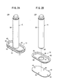
- FIG. 2A is a perspective view of the piston assembly 10A shown in FIG. 1 .
- FIG. 2B is a perspective view of constituent components prior to assembly (before joining) of the piston assembly 10A shown in FIG. 1 .
- the aforementioned piston main body 13 is constituted from a first piston member 40 and a second piston member 42. More specifically, the piston assembly 10A is constituted from the first piston member 40, the second piston member 42, and the piston rod 15.
- Each of the first piston member 40 and the second piston member 42 is an oval (substantially elliptical) plate-like member in its entirety, which is formed by plastic deformation (e.g., press working) of a metallic plate, and the first piston member 40 and the second piston member 42 are joined together mutually by welding. As will be described later, with the present embodiment, the first piston member 40 and the second piston member 42 are joined by projection welding.
- the first piston member 40 includes a flat oval base member 46, a side circumferential wall portion 48 that extends out in the axial direction from the entire circumference of the rim of the base member 46, and a flange 50 that spreads outwardly over the entire circumference from an end (an end on the distal end side of the piston rod 15) of the side circumferential wall portion 48.
- a circular through hole 47 is formed in the center of the base member 46 in the plate-thickness direction thereof.
- the second piston member 42 is an oval flat plate in its entirety, and as shown in FIG. 2B , prior to welding the first piston member 40 and the second piston member 42, a plurality of (four as exemplified in the drawing) welding projections (first welding projections) 44 are disposed on a surface of the second piston member 42 that is to be joined with the first piston member 40.
- the second piston member 42 has a predetermined plate-thickness in its entirety, and has no hole that penetrates in the plate-thickness direction thereof.
- the shape and size of the profile of the flange 50 of the first piston member 40, and the shape and size of the profile of the second piston member 42 are substantially the same.
- the seal installation groove 17 extends circumferentially between the outer peripheral edge of the second piston member 42 and the outer peripheral edge of the first piston member 40. More specifically, the seal installation groove 17 extends in an oval shape, which is the same as that of the piston main body 13 (the first piston member 40 and the second piston member 42).
- the piston rod 15 of the illustrated example includes a cylindrical body portion 54. On a proximal end of the body portion 54, there is formed a circular fitting portion 56, which projects concentrically with the body portion 54 (see FIGS. 3C and 3D ).
- the fitting portion 56 has an outer diameter, which is smaller than that of the body portion 54 of the piston rod 15. The outer diameter thereof is the same as, or slightly smaller than, the inner diameter of the through hole 47 provided on the first piston member 40.
- a circular shaped stepped portion is formed due to the different outer diameters of the body portion 54 and the fitting portion 56.
- the piston rod 15, prior to welding of the piston rod 15 and the piston main body 13, further includes a welding projection (second welding projection) 58, which is formed to project in the direction of the proximal end from a location in the vicinity of the peripheral edge portion of the fitting portion 56.
- the welding projection 58 in the illustrated example is formed in a circular ring shape.
- the welding projection 58 may also be constituted as a plurality of point-like projections or as a plurality of linear projections.
- the constituent materials of the first piston member 40, the second piston member 42, and the piston rod 15 are not particularly limited, insofar as they are materials (metals) capable of being welded, and are capable of ensuring the requisite strength. Suitable materials that can be used include, for example, iron and steel, stainless steel, aluminum, aluminum alloys, etc.
- the first piston member 40, the second piston member 42, and the piston rod 15, which are formed in the shapes shown in FIG. 2B , are prepared.
- the first piston member 40 and the second piston member 42 are joined mutually by projection welding.
- both members are energized electrically.
- the welding projections 44 provided on the second piston member 42 are melted by resistance heating, and as shown in FIG. 3B , the first piston member 40 and the second piston member 42 are joined mutually. In this manner, the piston main body 13 made up from the first piston member 40 and the second piston member 42 is manufactured.
- first piston member 40 and the second piston member 42 may be joined integrally by an adhesive, without providing the welding projections 44 on the second piston member 42.
- the piston main body 13 and the piston rod 15 are joined mutually by projection welding. Specifically, first, as shown in FIG. 3C , the piston rod 15 is placed in confronting relation against the piston main body 13. More specifically, the fitting portion 56 provided on the proximal end of the piston rod 15 is fitted into the through hole 47 disposed in the first piston member 40. Consequently, positioning of the piston rod 15 with respect to the piston main body 13 can be performed easily and accurately. Further, at this time, the welding projection 58 provided on the piston rod 15 abuts against the second piston member 42.
- both members are energized electrically.
- the welding projection 58 provided on the piston rod 15 is melted by resistance heating, and as shown in FIG. 3D , the piston main body 13 (second piston member 42) and the piston rod 15 are joined mutually. Consequently, the piston assembly 10A, which is constituted from the first piston member 40, the second piston member 42, and the piston rod 15, is obtained.
- the seal member 19 is mounted on the outer periphery (in the seal installation groove 17) of the piston main body 13 of the piston assembly 10A, which is manufactured in the foregoing manner, and as shown in FIG. 1 , the piston assembly 10A is arranged slidably in the interior of the housing 12, to thereby be assembled as the fluid pressure cylinder 11.
- piston rod 15 and the piston main body 13 may be joined integrally by an adhesive, without providing the welding projection 58 on the piston rod 15.
- the fluid pressure cylinder 11 equipped with the piston assembly 10A according to the present embodiment is constructed basically as described above. Next, operations and advantages thereof will be explained.
- the piston main body 13 is constructed from the first piston member 40 and the second piston member 42, which are made from plate-like members, compared to a piston main body having a considerable thickness, which is obtained by a forging or a cutting and machining process as in the conventional technique, the width of the piston main body 13 (thickness in the axial direction) can be shortened, and the total length of the fluid pressure cylinder 11 in which the piston assembly 10A is incorporated can be made shorter accordingly, while also enabling the cost of the fluid pressure cylinder 11 to be lowered.
- the stroke of the piston main body 13 can be lengthened. More specifically, without increasing the size and scale of the fluid pressure cylinder 11, an advantage is achieved in that the stroke can be increased in length.
- the through hole 47 in the plate-thickness direction is provided in the first piston member 40, and the fitting portion 56 that is fitted in the through hole 47 is formed to project on the one end of the piston rod 15. Accordingly, when the piston main body 13 and the piston rod 15 are welded, the fitting portion 56 provided on the one end of the piston rod 15 is fitted in the through hole 47 provided in the first piston member 40, whereby positioning of the piston rod 15 with respect to the piston main body 13 can be performed easily and accurately.
- piston assembly 10B according to a second embodiment will be described.
- elements thereof, which impart the same functions and effects as those of the piston assembly 10A according to the first embodiment, are denoted by the same reference characters and details thereof are omitted.
- the piston assembly 10B according to the second embodiment is equipped with a piston main body 60, the structure of which differs from that of the piston main body 13 shown in FIG. 1 , etc.
- the piston main body 60 is constituted from a first piston member 62 and a second piston member 64.
- Each of the first piston member 62 and the second piston member 64 is an oval plate-like member in its entirety, which is formed by plastic deformation (e.g., press working) of a metallic plate, and the first piston member 62 and the second piston member 64 are joined together mutually by welding. As will be described later, with the present embodiment, the first piston member 62 and the second piston member 64 are joined by projection welding.
- the first piston member 62 is substantially flat and oval over its entirety. As shown in FIG. 4B , a circular through hole 66 is formed that penetrates in the plate-thickness direction in the center of the first piston member 62. The inner diameter of the through hole 66 is the same or slightly larger than the outer diameter of the fitting portion 56 of the piston rod 15.
- the second piston member 64 includes a flat oval base member 68, a side circumferential wall portion 70 that extends out in the axial direction from the entire circumference of the rim of the base member 68, and a flange 72 that spreads outwardly over the entire circumference from an end (an end on the side away from the piston rod 15) of the side circumferential wall portion 70.
- a plurality of (four as exemplified in the drawing) welding projections 74 are disposed on a surface of the second piston member 64 that is to be joined with the first piston member 62.
- the second piston member 64 has a predetermined plate-thickness in its entirety, and has no hole that penetrates in the plate-thickness direction thereof.
- the shape and size of the profile of the first piston member 62 is substantially the same as the shape and size of the profile of the flange 72 of the second piston member 64.
- a seal installation groove 65 extends circumferentially between the outer peripheral edge of the first piston member 62 and the outer peripheral edge of the second piston member 64. More specifically, the seal installation groove 65 extends in an oval shape, which is the same as that of the piston main body 60 (the first piston member 62 and the second piston member 64).
- the piston assembly 10B For manufacturing the piston assembly 10B, in the same manner as the aforementioned piston assembly 10A according to the first embodiment, initially, the first piston member 62 and the second piston member 64 are joined by projection welding, and thereafter, the piston main body 60 and the piston rod 15 are joined by projection welding. In this manner, as shown in FIG. 4A and FIG. 5 , the piston assembly 10B, which is constituted from the first piston member 62, the second piston member 64, and the piston rod 15, is obtained.
- first piston member 62 and the second piston member 64 may be joined integrally by an adhesive, without providing the welding projections 74 on the second piston member 64.
- piston rod 15 and the piston main body 60 may be joined integrally by an adhesive, without providing the welding projection 58 on the piston rod 15.
- a seal member 19 is mounted on an outer circumferential portion (seal installation groove 65) of the piston main body 60 of the piston assembly 10B, which is manufactured in the foregoing manner, and the piston assembly 10B is arranged slidably in the interior of the housing 12 (see FIG. 1 ) to thereby be assembled as the fluid pressure cylinder 11.
- piston assembly 10C according to a third embodiment will be described.
- elements thereof, which impart the same functions and effects as those of the piston assembly 10A according to the first embodiment, are denoted by the same reference characters and details thereof are omitted.
- the piston assembly 10C includes a piston main body 80, and a piston rod 81 connected to the piston main body 80.
- the piston rod 81 is constructed with the fitting portion 56 being omitted from the piston rod 15 shown in FIG. 1 , etc.
- a welding projection 58 which is the same as the welding projection 58 shown in FIG. 3C , is provided on a proximal end surface of the piston rod 81.
- the piston main body 80 is constituted from a first piston member 82 and the second piston member 42.
- the first piston member 82 is constructed with the through hole 47 being omitted from the first piston member 40 shown in FIG. 2B , etc. More specifically, with the third embodiment, a through hole that penetrates in the plate-thickness direction is not provided in the first piston member 82, and the first piston member 82 is made up from a flat plate having a predetermined plate thickness over the entirety thereof.
- the second piston member 42 has the same structure as the second piston member 42 shown in FIGS. 2A and 2B .
- the piston assembly 10C For manufacturing the piston assembly 10C, in the same manner as the aforementioned piston assembly 10A according to the first embodiment, initially, the first piston member 82 and the second piston member 42 are joined by projection welding. Thereafter, the piston main body 80 and the piston rod 81 are joined by projection welding.
- the proximal end of the piston rod 81 is made to abut against a center portion of the first piston member 82, and in a condition in which pressure is applied in the axial direction to the piston rod 81 and the piston main body 80, both members are energized electrically. Accordingly, accompanying resistance heating thereof, by melting of the welding projection 58 disposed on the piston rod 81, as shown in FIG.
- the piston main body 80 (first piston member 82) and the piston rod 81 are joined mutually.
- the piston assembly 10C which is constituted from the first piston member 82, the second piston member 42, and the piston rod 81, is obtained.
- first piston member 82 and the second piston member 42 may be joined integrally by an adhesive, without providing the welding projections 44 on the second piston member 42.
- piston rod 81 and the piston main body 80 may be joined integrally by an adhesive, without providing the welding projection 58 on the piston rod 81.
- a seal member 19 is mounted on an outer circumferential portion (seal installation groove 17) of the piston main body 80 of the piston assembly 10C, which is manufactured in the foregoing manner, and the piston assembly 10C is arranged slidably in the interior of the housing 12 (see FIG. 1 ) to thereby be assembled as the fluid pressure cylinder 11.
- a piston main body 88 which is made up from a first piston member 84 and a second piston member 86, may be constituted with a circular shape. Apart from being circular shaped overall, the piston main body 88 (the first piston member 84 and the second piston member 86) has the same structure as the piston main body 13 (the first piston member 40 and the second piston member 42) shown in FIG. 2B , etc.
- the first piston member 84 includes a flat circular-shaped base member 90, a cylindrical side circumferential wall portion 92 that extends out in the axial direction from the entire circumference of the rim of the base member 90, and a flange 94 that spreads outward radially over the entire circumference from an end (an end on the distal end side of the piston rod 15) of the side circumferential wall portion 92.
- a circular through hole 47 is formed in the center of the base member 90 and penetrates in the plate-thickness direction thereof.
- the second piston member 86 is circular-shaped and substantially flat-plate-shaped in its entirety, and as shown in FIG. 8B , prior to welding the first piston member 84 and the second piston member 86, a plurality of (four as exemplified in the drawing) welding projections (first welding projections) 44 are disposed on a surface of the second piston member 86 that is to be joined with the first piston member 84.
- the second piston member 86 has a predetermined plate-thickness in its entirety, and has no hole that penetrates in the plate-thickness direction thereof.
- the outer diameters of the first piston member 84 and the second piston member 86 are substantially the same mutually.
- An annular seal installation groove 96 that extends circumferentially is formed by the flange 94 and the side circumferential wall portion 92 of the first piston member 84, and the outer peripheral edge of the second piston member 86.
- the piston assembly 10D can be assembled using the same procedure as that used for assembling the piston assembly 10A according to the first embodiment.
- a ring-shaped seal member 98 which is made from an elastic material (e.g., a rubber material), is mounted on the outer circumferential portion (seal installation groove 96) of the piston main body 88 of the piston assembly 10D.
- the piston assembly 10D with the seal member 98 mounted thereon is arranged slidably in the interior of a housing having a slide hole with a circular shape in cross section, to thereby be assembled as a fluid pressure cylinder.
- piston assembly 10E according to a fifth embodiment will be described.
- constituent elements thereof which are the same as those of the piston assemblies 10A, 10D according to the first and fourth embodiments, are denoted by the same reference characters and details thereof are omitted.
- the piston assembly 10E according to the fifth embodiment differs from the piston assembly 10D according to the fourth embodiment in relation to the construction of a piston main body 100.
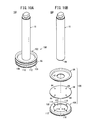
- the piston main body 100 is constituted from a first piston member 84, a second piston member 86, and a third piston member 106.
- the first piston member 84 and the second piston member 86, respectively, are constructed in the same manner as the first piston member 84 and the second piston member 86 shown in FIGS. 8A and 8B .
- the third piston member 106 includes a circular ring-shaped base member 108 with a circular opening 107 disposed therein, a side circumferential wall portion 110 that extends out in the axial direction from the entire circumference of the rim of the base member 108, and a flange 112 that spreads outwardly in a radial direction over the entire circumference from an end (an end on an opposite side from the piston rod 15 with the second piston member 86 acting as a reference) of the side circumferential wall portion 110.
- the circular opening 107 is provided in the base member 108 of the third piston member 106, the circular opening 107 may be omitted. More specifically, the third piston member 106 may be constituted without a hole that penetrates in the plate-thickness direction. As shown in FIG. 10B , the third piston member 106, prior to welding of the second piston member 86 and the third piston member 106, includes a plurality of (four as exemplified in the drawing) welding projections 114 disposed on a surface thereof that is to be joined with the second piston member 86. As shown in the drawing, the welding projections 114 are disposed circumferentially at equal intervals on the third piston member 106.
- the shape and size of the profile of the flange 112 of the third piston member 106, and the shape and size of the profile of the second piston member 86 are substantially the same. As shown in FIG. 10A , by means of the outer peripheral edge of the second piston member 86, and the side circumferential wall portion 110 and the flange 112 of the third piston member 106, a groove 116 is formed that extends circumferentially over a range of 360°.
- the first piston member 84 and the second piston member 86 are joined by projection welding. Thereafter, the second piston member 86 (the second piston member 86 with the first piston member 84 joined thereto) and the third piston member 106 are joined by projection welding. In this case, more specifically, in a condition in which the second piston member 86 and the third piston member 106 are superimposed concentrically and pressure is applied thereto, both members are energized electrically. Upon being energized, the welding projections 114 provided on the third piston member 106 are melted by resistance heating, whereupon the second piston member 86 and the third piston member 106 are joined together mutually.
- the piston main body 100 which is made up from the first piston member 84, the second piston member 86, and the third piston member 106, is manufactured.
- the first piston member 84 and the second piston member 86 may be joined together after the second piston member 86 and the third piston member 106 have been joined.
- the piston main body 100 and the piston rod 15 are joined mutually by projection welding. Welding in this case can be performed according to the welding technique used for the piston main body 13 and the piston rod 15 in the first embodiment.
- the piston assembly 10E which is constituted from the first piston member 84, the second piston member 86, the third piston member 106, and the piston rod 15, is obtained.
- first piston member 84 and the second piston member 86 may be joined integrally by an adhesive, without providing the welding projections 44 on the second piston member 86.
- second piston member 86 and the third piston member 106 may be joined integrally by an adhesive, without providing the welding projections 114 on the third piston member 106.
- the piston rod 15 and the piston main body 100 may be joined integrally by an adhesive, without providing the welding projection 58 on the piston rod 15.
- a ring-shaped seal member 98 which is made from an elastic material (e.g., a rubber material), is mounted on the outer circumferential portion (seal installation groove 96) of the piston main body 100 of the manufactured piston assembly 10E, and a ring-shaped or C-shaped wear ring (support member) 118, which is made from a low-friction material, is disposed in the groove 116.
- suitable low-friction materials for example, there may be cited synthetic resin materials equipped with both wear resistance and low friction, such as tetrafluoroethylene (PTFE), or metal materials or the like.
- the piston assembly 10E with the seal member 98 and the wear ring 118 mounted thereon is arranged slidably in the interior of a housing having a slide hole with a circular shape in cross section, to thereby be assembled as a fluid pressure cylinder. Since the wear ring 118 is made from a low-friction material, the coefficient of friction developed between the inner circumferential surface of the slide hole and the wear ring 118 is small, and to is the coefficient of friction between the inner circumferential surface of the slide hole and the seal member 98.
- the piston assembly 10E since the third piston member 106 constituting the groove 116 for installation of the wear ring 118 is made from a plate-like member, an increase in the axial width thereof is suppressed, while the piston main body 100 can be constructed having the groove 116 for enabling installation of the wear ring 118. Accordingly, by provision of the wear ring 118, along with shortening the width of the piston main body 100, the piston assembly 10E can be offered in which the overall length thereof is shortened.
- the piston main body 100 may be constituted in an oval shape in the same manner as the piston main body 13 of the first embodiment, or alternatively, in an elliptical shape.
- the seal member 98 is disposed between the first piston member 84 and the second piston member 86, and the wear ring 118 is disposed between the second piston member 86 and the third piston member 106.
- the seal member 98 and the wear ring 118 may be arranged in opposite locations. More specifically, the wear ring 118 may be disposed between the first piston member 84 and the second piston member 86, and the seal member 98 may be disposed between the second piston member 86 and the third piston member 106.
- piston assembly 10F according to a sixth embodiment will be described.
- constituent elements thereof which are the same as those of the piston assemblies 10A, 10D according to the first and fourth embodiments, are denoted by the same reference characters and details thereof are omitted.
- the piston assembly 10F according to the sixth embodiment, with respect to the piston assembly 10D according to the fourth embodiment, is further equipped with a third piston member 122 and a second piston rod 124.
- a piston main body 120 is constituted by the first piston member 84, the second piston member 86, and the third piston member 122, together with the piston rod 15 and the second piston rod 124, which is arranged on an opposite side, being disposed to sandwich the piston main body 120 therebetween.
- first piston rod 15 will be used to refer to the piston rod 15.
- the third piston member 122 includes a circular base member 126, a cylindrical side circumferential wall portion 128 that extends out in the axial direction from the entire circumference of the rim of the base member 126, and a flange 130 that spreads outwardly in a radial direction over the entire circumference from an end (an end on an opposite side from the piston rod with the second piston member 86 acting as a reference) of the side circumferential wall portion 128.
- a circular through hole 131 is formed to penetrate in the plate-thickness direction in the center of the base member 126.
- a plurality of (four as exemplified in the drawing) welding projections 129 are disposed on a surface thereof that is to be joined with the second piston member 86.
- the welding projections 129 are disposed circumferentially at equal intervals.
- the through hole 131 of the third piston member 122 has the same diameter as the through hole 47 of the first piston member 84.
- the shape and size of the profile of the flange 130 of the third piston member 122, and the shape and size of the profile of the second piston member 86 are the same or substantially the same. As shown in FIG. 12A , by means of the outer peripheral edge of the second piston member 86, and the side circumferential wall portion 128 and the flange 130 of the third piston member 122, a groove 132 is formed that extends circumferentially over a range of 360°.
- the first piston member 84, the second piston member 86, and the third piston member 122 are constituted from non-magnetic metals.
- suitable non-magnetic metals there may be cited aluminum alloys, copper alloys, zinc alloys, stainless steel, etc.
- the second piston rod 124 is constructed as with the case with the first piston rod 15. More specifically, the second piston rod 124 includes a body portion 134, and a fitting portion 136, which is disposed on a proximal end of the body portion 134. A welding projection 138 is provided on the second piston rod 124 prior to welding thereof with the piston main body 120.
- the body portion 134, the fitting portion 136, and the welding projection 138 are similar in construction respectively to the body portion 54, the fitting portion 56, and the welding projection 58 on the first piston rod 15 (see FIG. 3C ).
- the piston assembly 10F For manufacturing the piston assembly 10F, in the same manner as the aforementioned piston assembly 10A according to the first embodiment, initially, the first piston member 84 and the second piston member 86 are joined by projection welding. Thereafter, the second piston member 86 (the second piston member 86 with the first piston member 84 joined thereto) and the third piston member 122 are joined by projection welding. In this case, more specifically, in a condition in which the second piston member 86 and the third piston member 122 are superimposed concentrically and pressure is applied thereto, both members are energized electrically.
- the welding projections 129 provided on the third piston member 122 are melted by resistance heating, whereupon the second piston member 86 and the third piston member 122 are joined together mutually.
- the piston main body 120 which is made up from the first piston member 84, the second piston member 86, and the third piston member 122, is manufactured.
- the first piston member 84 and the second piston member 86 may be joined together after the second piston member 86 and the third piston member 122 have been joined.
- piston main body 120 and the first piston rod 15 are joined mutually by projection welding, and the piston main body 120 and the second piston rod 124 are joined mutually by projection welding.
- Welding of the piston main body 120 and the first piston rod 15 can be performed according to the welding technique used for the piston main body 13 and the piston rod 15 in the first embodiment.
- a proximal end of the second piston rod 124 is made to abut against the piston main body 120. More specifically, the fitting portion 136 provided on the proximal end of the second piston rod 124 is fitted in the through hole 131 of the third piston member 122. Consequently, positioning of the second piston rod 124 with respect to the piston main body 120 can be performed easily and accurately. Further, at this time, the welding projection 138 provided on the second piston rod 124 abuts against the second piston member 86.
- both members are energized electrically.
- the welding projection 138 provided on the second piston rod 124 is melted by resistance heating, and as shown in FIG. 13 , the piston main body 120 (second piston member 86) and the second piston rod 124 are joined together mutually.
- the piston assembly 10F which is constituted from the first piston member 84, the second piston member 86, the third piston member 122, the first piston rod 15, and the second piston rod 124, is obtained.
- first piston member 84 and the second piston member 86 may be joined integrally by an adhesive, without providing the welding projections 44 on the second piston member 86.
- second piston member 86 and the third piston member 122 may be joined integrally by an adhesive, without providing the welding projections 129 on the third piston member 122.
- the piston rod 15 and the piston main body 120 may be joined integrally by an adhesive, without providing the welding projection 58 on the first piston rod 15.
- the second piston rod 124 and the piston main body 120 may be joined integrally by an adhesive, without providing the welding projection 138 on the second piston rod 124.
- a ring-shaped seal member 98 is mounted on an outer circumferential portion (seal installation groove 96) of the piston main body 120 of the piston assembly 10F, and a magnet (permanent magnet) 140 is disposed in the groove 132.
- the magnet 140 is made of carbon steel, cobalt steel, Alnico, synthetic rubber, or other materials.
- the magnet 140 may be ring-shaped, or may be divided into plural sections in the circumferential direction. In the case that the magnet 140 is ring-shaped, the magnet 140 is installed on the side circumferential wall portion 128 of the third piston member 122, prior to the second piston member 86 and the third piston member 122 being joined.
- the piston assembly 10F with the seal member 98 and the magnet 140 mounted thereon is arranged slidably in the interior of a housing having a slide hole that is circular in cross section, to thereby be assembled as a fluid pressure cylinder.
- magnetic sensors are attached at positions corresponding to both stroke ends of the piston main body 120. Magnetism generated by the magnet 140 is sensed by the magnetic sensors, whereby the displacement position of the piston main body 120 is detected.
- the piston assembly 10F is of a so-called "double rod type" having the first piston rod 15 and the second piston rod 124.
- the width (thickness in the axial direction) of the piston main body 120 can be shortened. Accordingly, the total length of the piston assembly 10F can be made shorter, the device overall can be made smaller in scale, and costs therefor can be kept low.
- the piston main body 120 may be constituted in an oval shape in the same manner as the piston main body 13 of the first embodiment, or alternatively, in an elliptical shape.
- the seal member 98 is disposed between the first piston member 84 and the second piston member 86, and the magnet 140 is disposed between the second piston member 86 and the third piston member 122.
- the seal member 98 and the magnet 140 may be arranged in opposite locations. More specifically, the magnet 140 may be disposed between the first piston member 84 and the second piston member 86, and the seal member 98 may be disposed between the second piston member 86 and the third piston member 122.
- the respective constituent elements of the piston assemblies 10A through 10F are joined by projection welding.
- the present invention is not limited to this feature, and the respective constituent elements of the piston assemblies 10A through 10F may be joined by other welding methods aside from projection welding.
Landscapes
- Engineering & Computer Science (AREA)
- Mechanical Engineering (AREA)
- General Engineering & Computer Science (AREA)
- Chemical & Material Sciences (AREA)
- Combustion & Propulsion (AREA)
- Physics & Mathematics (AREA)
- Fluid Mechanics (AREA)
- Actuator (AREA)
- Pistons, Piston Rings, And Cylinders (AREA)
Abstract

Description
- The present invention relates to a piston assembly having a piston main body and a piston rod joined to the piston main body, a fluid pressure cylinder including the piston assembly, and a method for manufacturing the piston assembly.
- A known type of fluid pressure cylinder includes a cylinder, a piston disposed for displacement in an axial direction in the interior of the cylinder, and a piston rod connected to the piston. The fluid pressure cylinder is constituted such that the piston rod, which is connected to the piston, undergoes movement upon displacement of the piston by a fluid pressure. As a method for joining the piston and the piston rod, generally, a method by way of screw-engagement or a method that involves crimping is adopted. With the screw-engagement method, a screw hole (female screw threads) that penetrates through the piston in the axial direction is provided, whereas male screw threads are provided on one end of the piston rod, and the piston rod is attached directly to the piston by screw-engagement, or alternatively, a drill hole is provided in the piston, and the piston and the piston rod are joined by fastening a nut or the like to one end of the piston rod after the one end is inserted into the drill hole of the piston (see, for example,
FIG. 10 of Japanese Laid-Open Utility Model Publication No.58-123957 FIG. 1 of Japanese Laid-Open Utility Model Publication No.63-004406 - In the case of the aforementioned screw-engagement method, it is difficult for an airtight state to be maintained by the threads, and therefore, a seal member such as a separate O-ring must be provided on the fastening portion, and a process is required to provide a groove for installation of the seal member. Further, in the case of the screw-engagement method, a certain length for the screw is required in order to impart a strength sufficient to withstand the force generated by the fluid pressure, and it is difficult to shorten the length of the apparatus as a whole.
- With the crimping method, in order to provide sealing between the piston and the piston rod, a seal member must be disposed on the fitted portion, and a process is required to provide a groove for installation of the seal member. A certain amount of sealing capability may be imparted by plastic deformation of metal, however, in this case, there is a concern that a sufficient sealing capability cannot be obtained.
- The present invention has been made taking into consideration the aforementioned problems, and has an object of providing a piston assembly, a fluid pressure cylinder, and a method for manufacturing the piston assembly, in which it is unnecessary to dispose a seal member between the piston and the piston rod, and which enables the total length of the product to be shortened.
- To accomplish the aforementioned object, a piston assembly of the present invention comprises a piston main body, and a piston rod joined to the piston main body, wherein the piston main body includes a first piston member and a second piston member which are constituted from plate-like members, the first piston member and the second piston member are joined mutually under a condition of being superimposed in an axial direction of the piston rod, a seal installation groove that extends in a circumferential direction is formed between an outer peripheral edge of the first piston member and an outer peripheral edge of the second piston member, and at least one of the first piston member and the second piston member has a plate thickness over the entirety thereof.
- With the piston assembly of the present invention, since the piston main body is constructed from the first piston member and the second piston member which are constituted from plate-like members, the width of the piston (thickness in the axial direction) can be shortened, and the total length of the device of the fluid pressure cylinder in which the piston assembly is incorporated can be made shorter accordingly, while also enabling the cost of the device to be lowered. Further, since a through hole does not exist that penetrates in the axial direction through the piston main body, it is essentially unnecessary for a seal member to be disposed between the piston main body and the piston rod, thus enabling elimination of the seal member and a reduction in the number of parts. In addition, since a seal member is unneeded, provision of a sealing groove for installation thereof also is unnecessary, thus enabling the structure to be simplified. Further, in contradistinction to a structure equipped with a sealing function imparted by means of plastic deformation, such as by crimping or the like, concerns over reliability of the sealing function can fundamentally be avoided.
- In the above-described piston assembly, a through hole may be disposed in the first piston member so as to penetrate in the plate thickness direction, and a fitting portion that is fitted in the through hole may be formed to project on one end of the piston rod.
- According to the above structure, when the piston main body and the piston rod are welded, the fitting portion provided on the one end of the piston rod is fitted in the through hole provided in the first piston member, whereby positioning of the piston rod with respect to the piston main body can be carried out easily and accurately.
- In the above-described piston assembly, the piston main body may include a third piston member constituted from a plate-like member, and on an outer peripheral portion of the piston main body, a support member or a magnet that extends along the outer circumference of the piston main body may be disposed in a groove formed between the second piston member and the third piston member.
- According to the above structure, a piston assembly can be provided in which, even while equipped with the support member or the magnet, the total length thereof can be made shorter by shortening the width of the piston main body.
- In the above-described piston assembly, the piston rod may be joined as a first piston rod to one side of the piston main body by welding, and a second piston rod may be joined to another side of the piston main body.
- Due to the above structure, even in the case of a double rod type of piston assembly, the total length of the cylinder can be made shorter by shortening the width of the piston main body, the device can be made smaller in scale as a whole, and the cost of the device can be lowered.
- In the above-described piston assembly, the first piston member and the second piston member may be joined by welding, and the piston main body and the piston rod may also be joined by welding.
- According to the above structure, the first piston member and the second piston member can be joined reliably without providing a hole that penetrates in the thickness direction through the first piston member or the second piston member.
- Further, a fluid pressure cylinder according to the present invention comprises the piston assembly as described above, together with a housing that accommodates the piston assembly therein movably in the axial direction.
- According to the above-described fluid pressure cylinder, since the total length of the piston assembly can be shortened, the total length of the fluid pressure cylinder can be shortened as well.
- Further, a method for manufacturing a piston assembly according to the present invention comprises a first step of superimposing a first piston member and a second piston member which are constituted from plate-like members, and joining both members to obtain a piston main body, and a second step of joining a piston rod to the piston main body, wherein a seal installation groove that extends in a circumferential direction is formed between an outer peripheral edge of the first piston member and an outer peripheral edge of the second piston member, and at least one of the first piston member and the second piston member has a plate thickness over the entirety thereof.
- According to the above-described manufacturing method, the width of the piston (thickness in the axial direction) can be shortened, and since a seal member between the piston main body and the piston rod can be eliminated, the number of parts can be reduced, and the structure can be simplified by rendering unnecessary a seal groove for installation of the seal member.
- In the first step, the first piston member and the second piston member may be joined by welding, and in the second step, the piston main body and the piston rod may be joined by welding.
- According to the above structure, the first piston member and the second piston member can be joined reliably without providing a hole that penetrates in the thickness direction through the first piston member or the second piston member.
- According to the piston assembly, the fluid pressure cylinder, and the method for manufacturing a piston assembly according to the present invention, it is unnecessary for a seal member to be disposed between the piston main body and the piston rod, and the total length of the cylinder device can be shortened, or alternatively, if the piston assembly is incorporated in a cylinder device of the same length as a conventional cylinder device, an advantage is obtained in that the stroke of the cylinder device can be lengthened.
- The aforementioned objects, and other objects, characteristics, and advantages of the present invention will become more apparent from the following descriptions of preferred embodiments when taken in conjunction with the accompanying drawings.
-
-
FIG. 1 is a partially omitted vertical cross sectional view taken along an axial direction of a fluid pressure cylinder equipped with a piston assembly according to a first embodiment of the present invention; -
FIG. 2A is a perspective view of the piston assembly shown inFIG. 1 ; -
FIG. 2B is an exploded perspective view of the piston assembly shown inFIG. 1 ; -
FIG. 3A is a vertical cross sectional view prior to welding of a first piston member and a second piston member; -
FIG. 3B is a vertical cross sectional view after welding of the first piston member and the second piston member; -
FIG. 3C is a vertical cross sectional view prior to welding of a piston main body and a piston rod; -
FIG. 3D is a vertical cross sectional view after welding of the piston main body and the piston rod; -
FIG. 4A is a perspective view of a piston assembly according to a second embodiment of the present invention; -
FIG. 4B is an exploded perspective view of the piston assembly shown inFIG. 4A ; -
FIG. 5 is a vertical cross sectional view of a condition in which a seal member of the piston assembly shown inFIG. 4A is installed; -
FIG. 6A is a perspective view of a piston assembly according to a third embodiment of the present invention; -
FIG. 6B is an exploded perspective view of the piston assembly shown inFIG. 6A ; -
FIG. 7 is a vertical cross sectional view of a condition in which a seal member of the piston assembly shown inFIG. 6A is installed; -
FIG. 8A is a perspective view of a piston assembly according to a fourth embodiment of the present invention; -
FIG. 8B is an exploded perspective view of the piston assembly shown inFIG. 8A ; -
FIG. 9 is a vertical cross sectional view of a condition in which a seal member of the piston assembly shown inFIG. 8A is installed; -
FIG. 10A is a perspective view of a piston assembly according to a fifth embodiment of the present invention; -
FIG. 10B is an exploded perspective view of the piston assembly shown inFIG. 10A ; -
FIG. 11 is a vertical cross sectional view of a condition in which a seal member and a wear ring of the piston assembly shown inFIG. 10A are installed; -
FIG. 12A is a perspective view of a piston assembly according to a sixth embodiment of the present invention; -
FIG. 12B is an exploded perspective view of the piston assembly shown inFIG. 12A ; and -
FIG. 13 is a vertical cross sectional view of a condition in which a seal member and a magnet of the piston assembly shown inFIG. 12A are installed. - Below, descriptions will be given with reference to the accompanying drawings of preferred embodiments of a piston assembly, a fluid pressure cylinder, and a method for manufacturing the piston assembly according to the present invention.
-
FIG. 1 is a partially omitted vertical cross sectional view taken along an axial direction of afluid pressure cylinder 11 equipped with apiston assembly 10A according to a first embodiment of the present invention. Thefluid pressure cylinder 11 comprises, as basic constituent elements thereof, a housing (cylinder main body) 12, a pistonmain body 13 disposed movably in the axial direction in the interior of thehousing 12, and apiston rod 15 connected to the pistonmain body 13. Under an action of a fluid pressure, the pistonmain body 13 is moved in the axial direction within thehousing 12, whereby thepiston rod 15, which is connected to the pistonmain body 13, is moved reciprocally. - The
housing 12 is constituted from a metal material such as an aluminum alloy or the like, which is equipped with a pair ofports ports slide hole 18, the pistonmain body 13 is movable reciprocally in an axial direction within a certain restricted range. - The piston
main body 13 is accommodated inside thehousing 12. The pistonmain body 13 is a displaceable body that is displaceable in the axial direction (the direction of the arrow X inFIG. 1 ) of theslide hole 18 in a state in which the pistonmain body 13 partitions the interior of thehousing 12 into apressure chamber 20 on the side of oneport 14 and apressure chamber 22 on the side of theother port 16. On an outer circumference of the pistonmain body 13, aseal installation groove 17 is formed to extend along the outer circumference of the pistonmain body 13. A seal member (piston packing) 19 made from an elastic material (e.g., a rubber material) is mounted in theseal installation groove 17. - The
seal member 19 projects outwardly from an outermost circumferential portion of the pistonmain body 13 so as to circumferentially extend around the pistonmain body 13. The seal member, for example, is an O-ring made from an elastic material such as synthetic rubber or the like. Theseal member 19 provides sealing between the inner circumferential surface of theslide hole 18 and the outer circumferential surface of the pistonmain body 13, and the interior of thehousing 12 are partitioned into the twopressure chambers - A proximal end (an end in the direction of the arrow X2) of the
piston rod 15 is connected to the pistonmain body 13, and a distal end (an end in the direction of the arrow X1) of thepiston rod 15 penetrates through arod cover 30 that closes one end of theslide hole 18, and extends out to the exterior of theslide hole 18. In the present embodiment, thepiston assembly 10A is constituted from the pistonmain body 13 and thepiston rod 15. - A
seal member 34, which is made from an elastic material and provides sealing between an inner circumferential surface of therod cover 30 and an outer circumferential surface of thepiston rod 15, is installed in anannular groove 32 formed on an inner circumferential part of therod cover 30. Aseal member 38, which is made from an elastic material and provides sealing between the outer circumferential surface of therod cover 30 and an inner circumferential surface of theslide hole 18, is installed in anannular groove 36 formed on an outer circumferential part of therod cover 30. - With the
fluid pressure cylinder 11 constructed in the foregoing manner, from the aforementioned twoports pressure chambers main body 13 is moved reciprocally in the axial direction of theslide hole 18, and thepiston rod 15 undergoes advancing and retreating movements. -
FIG. 2A is a perspective view of thepiston assembly 10A shown inFIG. 1 .FIG. 2B is a perspective view of constituent components prior to assembly (before joining) of thepiston assembly 10A shown inFIG. 1 . The aforementioned pistonmain body 13 is constituted from afirst piston member 40 and asecond piston member 42. More specifically, thepiston assembly 10A is constituted from thefirst piston member 40, thesecond piston member 42, and thepiston rod 15. - Each of the
first piston member 40 and thesecond piston member 42 is an oval (substantially elliptical) plate-like member in its entirety, which is formed by plastic deformation (e.g., press working) of a metallic plate, and thefirst piston member 40 and thesecond piston member 42 are joined together mutually by welding. As will be described later, with the present embodiment, thefirst piston member 40 and thesecond piston member 42 are joined by projection welding. - The
first piston member 40 includes a flatoval base member 46, a sidecircumferential wall portion 48 that extends out in the axial direction from the entire circumference of the rim of thebase member 46, and aflange 50 that spreads outwardly over the entire circumference from an end (an end on the distal end side of the piston rod 15) of the sidecircumferential wall portion 48. A circular throughhole 47 is formed in the center of thebase member 46 in the plate-thickness direction thereof. - The
second piston member 42 is an oval flat plate in its entirety, and as shown inFIG. 2B , prior to welding thefirst piston member 40 and thesecond piston member 42, a plurality of (four as exemplified in the drawing) welding projections (first welding projections) 44 are disposed on a surface of thesecond piston member 42 that is to be joined with thefirst piston member 40. Thesecond piston member 42 has a predetermined plate-thickness in its entirety, and has no hole that penetrates in the plate-thickness direction thereof. - The shape and size of the profile of the
flange 50 of thefirst piston member 40, and the shape and size of the profile of thesecond piston member 42 are substantially the same. Theseal installation groove 17 extends circumferentially between the outer peripheral edge of thesecond piston member 42 and the outer peripheral edge of thefirst piston member 40. More specifically, theseal installation groove 17 extends in an oval shape, which is the same as that of the piston main body 13 (thefirst piston member 40 and the second piston member 42). - The
piston rod 15 of the illustrated example includes acylindrical body portion 54. On a proximal end of thebody portion 54, there is formed a circularfitting portion 56, which projects concentrically with the body portion 54 (seeFIGS. 3C and 3D ). Thefitting portion 56 has an outer diameter, which is smaller than that of thebody portion 54 of thepiston rod 15. The outer diameter thereof is the same as, or slightly smaller than, the inner diameter of the throughhole 47 provided on thefirst piston member 40. A circular shaped stepped portion is formed due to the different outer diameters of thebody portion 54 and thefitting portion 56. - The
piston rod 15, prior to welding of thepiston rod 15 and the pistonmain body 13, further includes a welding projection (second welding projection) 58, which is formed to project in the direction of the proximal end from a location in the vicinity of the peripheral edge portion of thefitting portion 56. Thewelding projection 58 in the illustrated example is formed in a circular ring shape. However, thewelding projection 58 may also be constituted as a plurality of point-like projections or as a plurality of linear projections. - The constituent materials of the
first piston member 40, thesecond piston member 42, and thepiston rod 15 are not particularly limited, insofar as they are materials (metals) capable of being welded, and are capable of ensuring the requisite strength. Suitable materials that can be used include, for example, iron and steel, stainless steel, aluminum, aluminum alloys, etc. - Next, a manufacturing method (assembly method) for the
piston assembly 10A will be described. First, thefirst piston member 40, thesecond piston member 42, and thepiston rod 15, which are formed in the shapes shown inFIG. 2B , are prepared. In addition, thefirst piston member 40 and thesecond piston member 42 are joined mutually by projection welding. In this case, more specifically, as shown inFIG. 3A , in a condition in which thefirst piston member 40 and thesecond piston member 42 are superimposed concentrically and pressure is applied thereto, both members are energized electrically. Upon being energized, thewelding projections 44 provided on thesecond piston member 42 are melted by resistance heating, and as shown inFIG. 3B , thefirst piston member 40 and thesecond piston member 42 are joined mutually. In this manner, the pistonmain body 13 made up from thefirst piston member 40 and thesecond piston member 42 is manufactured. - In this case, alternatively, the
first piston member 40 and thesecond piston member 42 may be joined integrally by an adhesive, without providing thewelding projections 44 on thesecond piston member 42. - Next, the piston
main body 13 and thepiston rod 15 are joined mutually by projection welding. Specifically, first, as shown inFIG. 3C , thepiston rod 15 is placed in confronting relation against the pistonmain body 13. More specifically, thefitting portion 56 provided on the proximal end of thepiston rod 15 is fitted into the throughhole 47 disposed in thefirst piston member 40. Consequently, positioning of thepiston rod 15 with respect to the pistonmain body 13 can be performed easily and accurately. Further, at this time, thewelding projection 58 provided on thepiston rod 15 abuts against thesecond piston member 42. - In addition, in a condition in which pressure is applied to the
piston rod 15 and the pistonmain body 13 in the axial direction, both members are energized electrically. Upon being energized, thewelding projection 58 provided on thepiston rod 15 is melted by resistance heating, and as shown inFIG. 3D , the piston main body 13 (second piston member 42) and thepiston rod 15 are joined mutually. Consequently, thepiston assembly 10A, which is constituted from thefirst piston member 40, thesecond piston member 42, and thepiston rod 15, is obtained. Theseal member 19 is mounted on the outer periphery (in the seal installation groove 17) of the pistonmain body 13 of thepiston assembly 10A, which is manufactured in the foregoing manner, and as shown inFIG. 1 , thepiston assembly 10A is arranged slidably in the interior of thehousing 12, to thereby be assembled as thefluid pressure cylinder 11. - In this case, alternatively, the
piston rod 15 and the pistonmain body 13 may be joined integrally by an adhesive, without providing thewelding projection 58 on thepiston rod 15. - The
fluid pressure cylinder 11 equipped with thepiston assembly 10A according to the present embodiment is constructed basically as described above. Next, operations and advantages thereof will be explained. - With the
piston assembly 10A, since the pistonmain body 13 is constructed from thefirst piston member 40 and thesecond piston member 42, which are made from plate-like members, compared to a piston main body having a considerable thickness, which is obtained by a forging or a cutting and machining process as in the conventional technique, the width of the piston main body 13 (thickness in the axial direction) can be shortened, and the total length of thefluid pressure cylinder 11 in which thepiston assembly 10A is incorporated can be made shorter accordingly, while also enabling the cost of thefluid pressure cylinder 11 to be lowered. Alternatively, even if thefluid pressure cylinder 11 is of the same length as the conventional device, by shortening the width (length in the axial direction) of the pistonmain body 13, the stroke of the pistonmain body 13 can be lengthened. More specifically, without increasing the size and scale of thefluid pressure cylinder 11, an advantage is achieved in that the stroke can be increased in length. - Although the through
hole 47 is disposed in thefirst piston member 40, a hole that penetrates in the plate-thickness direction is not provided in thesecond piston member 42. Thus, a hole does not exist that penetrates axially through the pistonmain body 13 as a whole. In this manner, because there is no hole that penetrates axially through the pistonmain body 13, it is essentially unnecessary for a seal member to be disposed between the pistonmain body 13 and thepiston rod 15, thus enabling elimination of such a seal member and a commensurate reduction in the number of parts. In addition, since such a seal member is unneeded, the provision of a sealing groove for installation thereof also is unnecessary, thus enabling the structure to be simplified. Furthermore, in contradistinction to a structure equipped with a sealing function imparted by means of plastic deformation, such as by crimping or the like, concerns over reliability of the sealing function can fundamentally be avoided. - With the
piston assembly 10A according to the present embodiment, the throughhole 47 in the plate-thickness direction is provided in thefirst piston member 40, and thefitting portion 56 that is fitted in the throughhole 47 is formed to project on the one end of thepiston rod 15. Accordingly, when the pistonmain body 13 and thepiston rod 15 are welded, thefitting portion 56 provided on the one end of thepiston rod 15 is fitted in the throughhole 47 provided in thefirst piston member 40, whereby positioning of thepiston rod 15 with respect to the pistonmain body 13 can be performed easily and accurately. - Next, with reference to
FIGS. 4A through 5 , apiston assembly 10B according to a second embodiment will be described. In thepiston assembly 10B according to the second embodiment, elements thereof, which impart the same functions and effects as those of thepiston assembly 10A according to the first embodiment, are denoted by the same reference characters and details thereof are omitted. - The
piston assembly 10B according to the second embodiment is equipped with a pistonmain body 60, the structure of which differs from that of the pistonmain body 13 shown inFIG. 1 , etc. The pistonmain body 60 is constituted from afirst piston member 62 and asecond piston member 64. - Each of the
first piston member 62 and thesecond piston member 64 is an oval plate-like member in its entirety, which is formed by plastic deformation (e.g., press working) of a metallic plate, and thefirst piston member 62 and thesecond piston member 64 are joined together mutually by welding. As will be described later, with the present embodiment, thefirst piston member 62 and thesecond piston member 64 are joined by projection welding. - The
first piston member 62 is substantially flat and oval over its entirety. As shown inFIG. 4B , a circular throughhole 66 is formed that penetrates in the plate-thickness direction in the center of thefirst piston member 62. The inner diameter of the throughhole 66 is the same or slightly larger than the outer diameter of thefitting portion 56 of thepiston rod 15. - The
second piston member 64 includes a flatoval base member 68, a sidecircumferential wall portion 70 that extends out in the axial direction from the entire circumference of the rim of thebase member 68, and aflange 72 that spreads outwardly over the entire circumference from an end (an end on the side away from the piston rod 15) of the sidecircumferential wall portion 70. Prior to welding thefirst piston member 62 and thesecond piston member 64, a plurality of (four as exemplified in the drawing)welding projections 74 are disposed on a surface of thesecond piston member 64 that is to be joined with thefirst piston member 62. Thesecond piston member 64 has a predetermined plate-thickness in its entirety, and has no hole that penetrates in the plate-thickness direction thereof. - The shape and size of the profile of the
first piston member 62 is substantially the same as the shape and size of the profile of theflange 72 of thesecond piston member 64. Aseal installation groove 65 extends circumferentially between the outer peripheral edge of thefirst piston member 62 and the outer peripheral edge of thesecond piston member 64. More specifically, theseal installation groove 65 extends in an oval shape, which is the same as that of the piston main body 60 (thefirst piston member 62 and the second piston member 64). - For manufacturing the
piston assembly 10B, in the same manner as theaforementioned piston assembly 10A according to the first embodiment, initially, thefirst piston member 62 and thesecond piston member 64 are joined by projection welding, and thereafter, the pistonmain body 60 and thepiston rod 15 are joined by projection welding. In this manner, as shown inFIG. 4A andFIG. 5 , thepiston assembly 10B, which is constituted from thefirst piston member 62, thesecond piston member 64, and thepiston rod 15, is obtained. - In this case, the
first piston member 62 and thesecond piston member 64 may be joined integrally by an adhesive, without providing thewelding projections 74 on thesecond piston member 64. Further, thepiston rod 15 and the pistonmain body 60 may be joined integrally by an adhesive, without providing thewelding projection 58 on thepiston rod 15. - A
seal member 19 is mounted on an outer circumferential portion (seal installation groove 65) of the pistonmain body 60 of thepiston assembly 10B, which is manufactured in the foregoing manner, and thepiston assembly 10B is arranged slidably in the interior of the housing 12 (seeFIG. 1 ) to thereby be assembled as thefluid pressure cylinder 11. - In the second embodiment, concerning respective constituent elements thereof that are common with the first embodiment, it is a matter of course that the obtained operations and effects are the same or similar to those operations and effects possessed by the respective common constituent elements in the first embodiment.
- Next, with reference to
FIGS. 6A through 7 , apiston assembly 10C according to a third embodiment will be described. In thepiston assembly 10C according to the third embodiment, elements thereof, which impart the same functions and effects as those of thepiston assembly 10A according to the first embodiment, are denoted by the same reference characters and details thereof are omitted. - The
piston assembly 10C according to the third embodiment includes a pistonmain body 80, and apiston rod 81 connected to the pistonmain body 80. Thepiston rod 81 is constructed with thefitting portion 56 being omitted from thepiston rod 15 shown inFIG. 1 , etc. Awelding projection 58, which is the same as thewelding projection 58 shown inFIG. 3C , is provided on a proximal end surface of thepiston rod 81. - The piston
main body 80 is constituted from afirst piston member 82 and thesecond piston member 42. Thefirst piston member 82 is constructed with the throughhole 47 being omitted from thefirst piston member 40 shown inFIG. 2B , etc. More specifically, with the third embodiment, a through hole that penetrates in the plate-thickness direction is not provided in thefirst piston member 82, and thefirst piston member 82 is made up from a flat plate having a predetermined plate thickness over the entirety thereof. Thesecond piston member 42 has the same structure as thesecond piston member 42 shown inFIGS. 2A and 2B . - For manufacturing the
piston assembly 10C, in the same manner as theaforementioned piston assembly 10A according to the first embodiment, initially, thefirst piston member 82 and thesecond piston member 42 are joined by projection welding. Thereafter, the pistonmain body 80 and thepiston rod 81 are joined by projection welding. In this case, with the present embodiment, the proximal end of thepiston rod 81 is made to abut against a center portion of thefirst piston member 82, and in a condition in which pressure is applied in the axial direction to thepiston rod 81 and the pistonmain body 80, both members are energized electrically. Accordingly, accompanying resistance heating thereof, by melting of thewelding projection 58 disposed on thepiston rod 81, as shown inFIG. 7 , the piston main body 80 (first piston member 82) and thepiston rod 81 are joined mutually. In this manner, thepiston assembly 10C, which is constituted from thefirst piston member 82, thesecond piston member 42, and thepiston rod 81, is obtained. - In this case, the
first piston member 82 and thesecond piston member 42 may be joined integrally by an adhesive, without providing thewelding projections 44 on thesecond piston member 42. Further, thepiston rod 81 and the pistonmain body 80 may be joined integrally by an adhesive, without providing thewelding projection 58 on thepiston rod 81. - A
seal member 19 is mounted on an outer circumferential portion (seal installation groove 17) of the pistonmain body 80 of thepiston assembly 10C, which is manufactured in the foregoing manner, and thepiston assembly 10C is arranged slidably in the interior of the housing 12 (seeFIG. 1 ) to thereby be assembled as thefluid pressure cylinder 11. - In the third embodiment, concerning respective constituent elements thereof that are common with the first embodiment, it is a matter of course that the obtained operations and effects are the same or similar to those operations and effects possessed by the respective common constituent elements in the first embodiment.
- In a
piston assembly 10D according to a fourth embodiment shown inFIGS. 8A through 9 , a pistonmain body 88, which is made up from afirst piston member 84 and asecond piston member 86, may be constituted with a circular shape. Apart from being circular shaped overall, the piston main body 88 (thefirst piston member 84 and the second piston member 86) has the same structure as the piston main body 13 (thefirst piston member 40 and the second piston member 42) shown inFIG. 2B , etc. - More specifically, the
first piston member 84 includes a flat circular-shapedbase member 90, a cylindrical sidecircumferential wall portion 92 that extends out in the axial direction from the entire circumference of the rim of thebase member 90, and aflange 94 that spreads outward radially over the entire circumference from an end (an end on the distal end side of the piston rod 15) of the sidecircumferential wall portion 92. A circular throughhole 47 is formed in the center of thebase member 90 and penetrates in the plate-thickness direction thereof. - The
second piston member 86 is circular-shaped and substantially flat-plate-shaped in its entirety, and as shown inFIG. 8B , prior to welding thefirst piston member 84 and thesecond piston member 86, a plurality of (four as exemplified in the drawing) welding projections (first welding projections) 44 are disposed on a surface of thesecond piston member 86 that is to be joined with thefirst piston member 84. Thesecond piston member 86 has a predetermined plate-thickness in its entirety, and has no hole that penetrates in the plate-thickness direction thereof. The outer diameters of thefirst piston member 84 and thesecond piston member 86 are substantially the same mutually. - An annular
seal installation groove 96 that extends circumferentially is formed by theflange 94 and the sidecircumferential wall portion 92 of thefirst piston member 84, and the outer peripheral edge of thesecond piston member 86. - The
piston assembly 10D can be assembled using the same procedure as that used for assembling thepiston assembly 10A according to the first embodiment. As shown inFIG. 9 , a ring-shapedseal member 98, which is made from an elastic material (e.g., a rubber material), is mounted on the outer circumferential portion (seal installation groove 96) of the pistonmain body 88 of thepiston assembly 10D. Thepiston assembly 10D with theseal member 98 mounted thereon is arranged slidably in the interior of a housing having a slide hole with a circular shape in cross section, to thereby be assembled as a fluid pressure cylinder. - In accordance with the
piston assembly 10D according to the fourth embodiment, the same advantages and effects as those of thepiston assembly 10A according to the first embodiment are obtained. - Next, with reference to
FIGS. 10A through 11 , apiston assembly 10E according to a fifth embodiment will be described. In thepiston assembly 10E according to the fifth embodiment, constituent elements thereof, which are the same as those of thepiston assemblies - The
piston assembly 10E according to the fifth embodiment differs from thepiston assembly 10D according to the fourth embodiment in relation to the construction of a pistonmain body 100. The pistonmain body 100 is constituted from afirst piston member 84, asecond piston member 86, and athird piston member 106. Thefirst piston member 84 and thesecond piston member 86, respectively, are constructed in the same manner as thefirst piston member 84 and thesecond piston member 86 shown inFIGS. 8A and 8B . - The
third piston member 106 includes a circular ring-shapedbase member 108 with acircular opening 107 disposed therein, a sidecircumferential wall portion 110 that extends out in the axial direction from the entire circumference of the rim of thebase member 108, and aflange 112 that spreads outwardly in a radial direction over the entire circumference from an end (an end on an opposite side from thepiston rod 15 with thesecond piston member 86 acting as a reference) of the sidecircumferential wall portion 110. - Although, as shown in the illustrated example, the
circular opening 107 is provided in thebase member 108 of thethird piston member 106, thecircular opening 107 may be omitted. More specifically, thethird piston member 106 may be constituted without a hole that penetrates in the plate-thickness direction. As shown inFIG. 10B , thethird piston member 106, prior to welding of thesecond piston member 86 and thethird piston member 106, includes a plurality of (four as exemplified in the drawing)welding projections 114 disposed on a surface thereof that is to be joined with thesecond piston member 86. As shown in the drawing, thewelding projections 114 are disposed circumferentially at equal intervals on thethird piston member 106. - The shape and size of the profile of the
flange 112 of thethird piston member 106, and the shape and size of the profile of thesecond piston member 86 are substantially the same. As shown inFIG. 10A , by means of the outer peripheral edge of thesecond piston member 86, and the sidecircumferential wall portion 110 and theflange 112 of thethird piston member 106, agroove 116 is formed that extends circumferentially over a range of 360°. - For manufacturing the
piston assembly 10E, in the same manner as theaforementioned piston assembly 10A according to the first embodiment, initially, thefirst piston member 84 and thesecond piston member 86 are joined by projection welding. Thereafter, the second piston member 86 (thesecond piston member 86 with thefirst piston member 84 joined thereto) and thethird piston member 106 are joined by projection welding. In this case, more specifically, in a condition in which thesecond piston member 86 and thethird piston member 106 are superimposed concentrically and pressure is applied thereto, both members are energized electrically. Upon being energized, thewelding projections 114 provided on thethird piston member 106 are melted by resistance heating, whereupon thesecond piston member 86 and thethird piston member 106 are joined together mutually. In this manner, the pistonmain body 100, which is made up from thefirst piston member 84, thesecond piston member 86, and thethird piston member 106, is manufactured. Alternatively, thefirst piston member 84 and thesecond piston member 86 may be joined together after thesecond piston member 86 and thethird piston member 106 have been joined. - Next, the piston
main body 100 and thepiston rod 15 are joined mutually by projection welding. Welding in this case can be performed according to the welding technique used for the pistonmain body 13 and thepiston rod 15 in the first embodiment. As a result, thepiston assembly 10E, which is constituted from thefirst piston member 84, thesecond piston member 86, thethird piston member 106, and thepiston rod 15, is obtained. - In this case, the
first piston member 84 and thesecond piston member 86 may be joined integrally by an adhesive, without providing thewelding projections 44 on thesecond piston member 86. Further, thesecond piston member 86 and thethird piston member 106 may be joined integrally by an adhesive, without providing thewelding projections 114 on thethird piston member 106. Thepiston rod 15 and the pistonmain body 100 may be joined integrally by an adhesive, without providing thewelding projection 58 on thepiston rod 15. - As shown in
FIG. 11 , a ring-shapedseal member 98, which is made from an elastic material (e.g., a rubber material), is mounted on the outer circumferential portion (seal installation groove 96) of the pistonmain body 100 of the manufacturedpiston assembly 10E, and a ring-shaped or C-shaped wear ring (support member) 118, which is made from a low-friction material, is disposed in thegroove 116. As suitable low-friction materials, for example, there may be cited synthetic resin materials equipped with both wear resistance and low friction, such as tetrafluoroethylene (PTFE), or metal materials or the like. In a condition in which thewear ring 118 is installed in thegroove 116, the outer diameter of thewear ring 118 is greater than the outer diameters of thesecond piston member 86 and thethird piston member 106. - The
piston assembly 10E with theseal member 98 and thewear ring 118 mounted thereon is arranged slidably in the interior of a housing having a slide hole with a circular shape in cross section, to thereby be assembled as a fluid pressure cylinder. Since thewear ring 118 is made from a low-friction material, the coefficient of friction developed between the inner circumferential surface of the slide hole and thewear ring 118 is small, and to is the coefficient of friction between the inner circumferential surface of the slide hole and theseal member 98. - During operation of the fluid pressure cylinder equipped with the
piston assembly 10E, in the event that a large lateral load, which acts in a direction perpendicular to the axial direction, is applied to the pistonmain body 100, the outer circumferential surface of thewear ring 118, which projects outwardly beyond the outermost circumferential portion of the pistonmain body 100, is placed in contact with the slide hole, whereby the outer circumference of the pistonmain body 100 is prevented from contacting the inner circumferential surface of the slide hole. - In the case of the
piston assembly 10E according to the present embodiment, since thethird piston member 106 constituting thegroove 116 for installation of thewear ring 118 is made from a plate-like member, an increase in the axial width thereof is suppressed, while the pistonmain body 100 can be constructed having thegroove 116 for enabling installation of thewear ring 118. Accordingly, by provision of thewear ring 118, along with shortening the width of the pistonmain body 100, thepiston assembly 10E can be offered in which the overall length thereof is shortened. - Further, the same advantages and effects as those of the
piston assembly 10A according to the first embodiment are obtained in accordance with thepiston assembly 10E according to the fifth embodiment. - As modifications of the
piston assembly 10E, the pistonmain body 100 may be constituted in an oval shape in the same manner as the pistonmain body 13 of the first embodiment, or alternatively, in an elliptical shape. - With the
piston assembly 10E, theseal member 98 is disposed between thefirst piston member 84 and thesecond piston member 86, and thewear ring 118 is disposed between thesecond piston member 86 and thethird piston member 106. However, theseal member 98 and thewear ring 118 may be arranged in opposite locations. More specifically, thewear ring 118 may be disposed between thefirst piston member 84 and thesecond piston member 86, and theseal member 98 may be disposed between thesecond piston member 86 and thethird piston member 106. - Next, with reference to
FIGS. 12A through 13 , apiston assembly 10F according to a sixth embodiment will be described. In thepiston assembly 10F according to the sixth embodiment, constituent elements thereof, which are the same as those of thepiston assemblies - The
piston assembly 10F according to the sixth embodiment, with respect to thepiston assembly 10D according to the fourth embodiment, is further equipped with athird piston member 122 and asecond piston rod 124. More specifically, with the present embodiment, a pistonmain body 120 is constituted by thefirst piston member 84, thesecond piston member 86, and thethird piston member 122, together with thepiston rod 15 and thesecond piston rod 124, which is arranged on an opposite side, being disposed to sandwich the pistonmain body 120 therebetween. Below, in the present embodiment, the term "first piston rod 15" will be used to refer to thepiston rod 15. - The
third piston member 122 includes acircular base member 126, a cylindrical sidecircumferential wall portion 128 that extends out in the axial direction from the entire circumference of the rim of thebase member 126, and aflange 130 that spreads outwardly in a radial direction over the entire circumference from an end (an end on an opposite side from the piston rod with thesecond piston member 86 acting as a reference) of the sidecircumferential wall portion 128. A circular throughhole 131 is formed to penetrate in the plate-thickness direction in the center of thebase member 126. - As shown in
FIG. 12B , on thethird piston member 122, prior to being joined to thesecond piston member 86 by welding, a plurality of (four as exemplified in the drawing)welding projections 129 are disposed on a surface thereof that is to be joined with thesecond piston member 86. On the illustratedthird piston member 122, thewelding projections 129 are disposed circumferentially at equal intervals. The throughhole 131 of thethird piston member 122 has the same diameter as the throughhole 47 of thefirst piston member 84. - The shape and size of the profile of the
flange 130 of thethird piston member 122, and the shape and size of the profile of thesecond piston member 86 are the same or substantially the same. As shown inFIG. 12A , by means of the outer peripheral edge of thesecond piston member 86, and the sidecircumferential wall portion 128 and theflange 130 of thethird piston member 122, agroove 132 is formed that extends circumferentially over a range of 360°. - In the present embodiment, the
first piston member 84, thesecond piston member 86, and thethird piston member 122 are constituted from non-magnetic metals. As suitable non-magnetic metals, there may be cited aluminum alloys, copper alloys, zinc alloys, stainless steel, etc. - The
second piston rod 124 is constructed as with the case with thefirst piston rod 15. More specifically, thesecond piston rod 124 includes abody portion 134, and afitting portion 136, which is disposed on a proximal end of thebody portion 134. Awelding projection 138 is provided on thesecond piston rod 124 prior to welding thereof with the pistonmain body 120. Thebody portion 134, thefitting portion 136, and thewelding projection 138 are similar in construction respectively to thebody portion 54, thefitting portion 56, and thewelding projection 58 on the first piston rod 15 (seeFIG. 3C ). - For manufacturing the
piston assembly 10F, in the same manner as theaforementioned piston assembly 10A according to the first embodiment, initially, thefirst piston member 84 and thesecond piston member 86 are joined by projection welding. Thereafter, the second piston member 86 (thesecond piston member 86 with thefirst piston member 84 joined thereto) and thethird piston member 122 are joined by projection welding. In this case, more specifically, in a condition in which thesecond piston member 86 and thethird piston member 122 are superimposed concentrically and pressure is applied thereto, both members are energized electrically. - Upon being energized, the
welding projections 129 provided on thethird piston member 122 are melted by resistance heating, whereupon thesecond piston member 86 and thethird piston member 122 are joined together mutually. In this manner, the pistonmain body 120, which is made up from thefirst piston member 84, thesecond piston member 86, and thethird piston member 122, is manufactured. Alternatively, thefirst piston member 84 and thesecond piston member 86 may be joined together after thesecond piston member 86 and thethird piston member 122 have been joined. - Next, the piston
main body 120 and thefirst piston rod 15 are joined mutually by projection welding, and the pistonmain body 120 and thesecond piston rod 124 are joined mutually by projection welding. Welding of the pistonmain body 120 and thefirst piston rod 15 can be performed according to the welding technique used for the pistonmain body 13 and thepiston rod 15 in the first embodiment. - To join the piston
main body 120 and thesecond piston rod 124, first, a proximal end of thesecond piston rod 124 is made to abut against the pistonmain body 120. More specifically, thefitting portion 136 provided on the proximal end of thesecond piston rod 124 is fitted in the throughhole 131 of thethird piston member 122. Consequently, positioning of thesecond piston rod 124 with respect to the pistonmain body 120 can be performed easily and accurately. Further, at this time, thewelding projection 138 provided on thesecond piston rod 124 abuts against thesecond piston member 86. - In addition, in a condition in which pressure is applied to the
second piston rod 124 and the pistonmain body 120 in the axial direction, both members are energized electrically. Upon being energized, thewelding projection 138 provided on thesecond piston rod 124 is melted by resistance heating, and as shown inFIG. 13 , the piston main body 120 (second piston member 86) and thesecond piston rod 124 are joined together mutually. In this manner, thepiston assembly 10F, which is constituted from thefirst piston member 84, thesecond piston member 86, thethird piston member 122, thefirst piston rod 15, and thesecond piston rod 124, is obtained. - Concerning the timing at which welding of the piston
main body 120 and thefirst piston rod 15 is implemented, and the timing at which welding of the pistonmain body 120 and thesecond piston rod 124 is implemented, either one may be performed first, or both may be performed simultaneously. - Alternatively, the
first piston member 84 and thesecond piston member 86 may be joined integrally by an adhesive, without providing thewelding projections 44 on thesecond piston member 86. Further, thesecond piston member 86 and thethird piston member 122 may be joined integrally by an adhesive, without providing thewelding projections 129 on thethird piston member 122. Thepiston rod 15 and the pistonmain body 120 may be joined integrally by an adhesive, without providing thewelding projection 58 on thefirst piston rod 15. Thesecond piston rod 124 and the pistonmain body 120 may be joined integrally by an adhesive, without providing thewelding projection 138 on thesecond piston rod 124. - As shown in
FIG. 13 , a ring-shapedseal member 98 is mounted on an outer circumferential portion (seal installation groove 96) of the pistonmain body 120 of thepiston assembly 10F, and a magnet (permanent magnet) 140 is disposed in thegroove 132. Themagnet 140 is made of carbon steel, cobalt steel, Alnico, synthetic rubber, or other materials. Themagnet 140 may be ring-shaped, or may be divided into plural sections in the circumferential direction. In the case that themagnet 140 is ring-shaped, themagnet 140 is installed on the sidecircumferential wall portion 128 of thethird piston member 122, prior to thesecond piston member 86 and thethird piston member 122 being joined. - The
piston assembly 10F with theseal member 98 and themagnet 140 mounted thereon is arranged slidably in the interior of a housing having a slide hole that is circular in cross section, to thereby be assembled as a fluid pressure cylinder. In this case, on an outer surface of the housing, magnetic sensors are attached at positions corresponding to both stroke ends of the pistonmain body 120. Magnetism generated by themagnet 140 is sensed by the magnetic sensors, whereby the displacement position of the pistonmain body 120 is detected. - The
piston assembly 10F according to the present embodiment is of a so-called "double rod type" having thefirst piston rod 15 and thesecond piston rod 124. However, compared to a conventional double rod type of piston assembly, the width (thickness in the axial direction) of the pistonmain body 120 can be shortened. Accordingly, the total length of thepiston assembly 10F can be made shorter, the device overall can be made smaller in scale, and costs therefor can be kept low. - Further, the same advantages and effects as those of the
piston assembly 10A according to the first embodiment are obtained in accordance with thepiston assembly 10F according to the sixth embodiment. - As a modification of the
piston assembly 10F, a form may be adopted that does not include thesecond piston rod 124. Further, as another modification of thepiston assembly 10F, the pistonmain body 120 may be constituted in an oval shape in the same manner as the pistonmain body 13 of the first embodiment, or alternatively, in an elliptical shape. - With the
piston assembly 10F, theseal member 98 is disposed between thefirst piston member 84 and thesecond piston member 86, and themagnet 140 is disposed between thesecond piston member 86 and thethird piston member 122. However, theseal member 98 and themagnet 140 may be arranged in opposite locations. More specifically, themagnet 140 may be disposed between thefirst piston member 84 and thesecond piston member 86, and theseal member 98 may be disposed between thesecond piston member 86 and thethird piston member 122. - In the aforementioned embodiments, the respective constituent elements of the
piston assemblies 10A through 10F are joined by projection welding. However, the present invention is not limited to this feature, and the respective constituent elements of thepiston assemblies 10A through 10F may be joined by other welding methods aside from projection welding. - Although preferred embodiments of the present invention have been described above, the present invention is not limited to the aforementioned embodiments, and various changes and modifications may be made thereto without departing from the scope of the invention.
Claims (8)
- A piston assembly (10A to 10F) comprising:a piston main body (13, 60, 80, 88, 100, 120); anda piston rod (15) joined to the piston main body (13, 60, 80, 88, 100, 120), wherein:the piston main body (13, 60, 80, 88, 100, 120) includes a first piston member (40, 62, 82, 84) and a second piston member (42, 64, 86) which are constituted from plate-like members;the first piston member (40, 62, 82, 84) and the second piston member (42, 64, 86) are joined mutually under a condition of being superimposed in an axial direction of the piston rod (15);a seal installation groove (17, 65, 96) that extends in a circumferential direction is formed between an outer peripheral edge of the first piston member (40, 62, 82, 84) and an outer peripheral edge of the second piston member (42, 64, 86); andat least one of the first piston member (40, 62, 82, 84) and the second piston member (42, 64, 86) has a plate thickness over the entirety thereof.
- The piston assembly (10A, 10B, 10D to 10F) according to claim 1, wherein:a through hole (47) is disposed in the first piston member (40, 62, 84) so as to penetrate in a plate thickness direction thereof; anda fitting portion (56) that is fitted in the through hole (47) is formed to project on one end of the piston rod (15).
- The piston assembly (10E, 10F) according to claim 1, wherein:the piston main body (100, 120) includes a third piston member (106, 122) constituted from a plate-like member; andon an outer peripheral portion of the piston main body (100, 120), a support member (118) or a magnet (140) that extends along an outer circumference of the piston main body (100, 120) is disposed in a groove (116, 132) formed between the second piston member (86) and the third piston member (106, 122).
- The piston assembly (10F) according to claim 1, wherein:the piston rod (15) is joined as a first piston rod (15) to one side of the piston main body (120) by welding; anda second piston rod (124) is joined to another side of the piston main body (120).
- The piston assembly (10A to 10F) according to claim 1, wherein:the first piston member (40, 62, 82, 84) and the second piston member (42, 64, 86) are joined by welding; andthe piston main body (13, 60, 80, 88, 100, 120) and the piston rod (15) are joined by welding.
- A fluid pressure cylinder (11) comprising:the piston assembly (10A to 10F) according to claim 1; anda housing (12) that accommodates the piston assembly (10A to 10F) therein movably in the axial direction.
- A method for manufacturing a piston assembly (10A to 10F) comprising:a first step of superimposing a first piston member (40, 62, 82, 84) and a second piston member (42, 64, 86) which are constituted from plate-like members, and joining both members to obtain a piston main body (13, 60, 80, 88, 100, 120); anda second step of joining a piston rod (15) to the piston main body (13, 60, 80, 88, 100, 120), wherein:a seal installation groove (17, 65, 96) that extends in a circumferential direction is formed between an outer peripheral edge of the first piston member (40, 62, 82, 84) and an outer peripheral edge of the second piston member (42, 64, 86); andat least one of the first piston member (40, 62, 82, 84) and the second piston member (42, 64, 86) has a plate thickness over the entirety thereof.
- The method for manufacturing a piston assembly (10A to 10F) according to claim 7, wherein:in the first step, the first piston member (40, 62, 82, 84) and the second piston member (42, 64, 86) are joined by welding; andin the second step, the piston main body (13, 60, 80, 88, 100, 120) and the piston rod (15) are joined by welding.
Applications Claiming Priority (2)
| Application Number | Priority Date | Filing Date | Title |
|---|---|---|---|
| JP2011124756A JP5435434B2 (en) | 2011-06-03 | 2011-06-03 | Piston assembly, fluid pressure cylinder, and method of manufacturing piston assembly |
| PCT/JP2012/063083 WO2012165232A1 (en) | 2011-06-03 | 2012-05-22 | Piston assembly, fluid pressure cylinder, method for manufacturing piston assembly |
Publications (3)
| Publication Number | Publication Date |
|---|---|
| EP2716920A1 true EP2716920A1 (en) | 2014-04-09 |
| EP2716920A4 EP2716920A4 (en) | 2015-05-20 |
| EP2716920B1 EP2716920B1 (en) | 2017-03-22 |
Family
ID=47259093
Family Applications (1)
| Application Number | Title | Priority Date | Filing Date |
|---|---|---|---|
| EP12792299.5A Not-in-force EP2716920B1 (en) | 2011-06-03 | 2012-05-22 | Piston assembly, fluid pressure cylinder, method for manufacturing piston assembly |
Country Status (9)
| Country | Link |
|---|---|
| US (1) | US9765800B2 (en) |
| EP (1) | EP2716920B1 (en) |
| JP (1) | JP5435434B2 (en) |
| KR (1) | KR101540949B1 (en) |
| CN (1) | CN103620234B (en) |
| BR (1) | BR112013031008B1 (en) |
| MX (1) | MX349599B (en) |
| TW (1) | TWI453352B (en) |
| WO (1) | WO2012165232A1 (en) |
Cited By (9)
| Publication number | Priority date | Publication date | Assignee | Title |
|---|---|---|---|---|
| WO2016089392A1 (en) * | 2014-12-03 | 2016-06-09 | New York Air Brake, LLC | Improved brake piston assembly |
| WO2016199372A1 (en) * | 2015-06-11 | 2016-12-15 | Smc Corporation | Fluid pressure cylinder |
| WO2018011240A1 (en) * | 2016-07-13 | 2018-01-18 | Newfrey Llc | Joining head and joining device with reduced interfering contour |
| US10035526B2 (en) | 2014-12-03 | 2018-07-31 | New York Air Brake, LLC | Brake piston assembly |
| CN109175744A (en) * | 2018-10-15 | 2019-01-11 | 仪征常众汽车部件有限公司 | A kind of welding procedure for cooler bin in New-energy electric vehicle |
| US10662982B2 (en) | 2015-06-11 | 2020-05-26 | Smc Corporation | Fluid pressure cylinder |
| US10662981B2 (en) | 2015-06-11 | 2020-05-26 | Smc Corporation | Fluid pressure cylinder |
| US10670053B2 (en) | 2015-06-11 | 2020-06-02 | Smc Corporation | Fluid pressure cylinder |
| US10677270B2 (en) | 2015-06-11 | 2020-06-09 | Smc Corporation | Fluid pressure cylinder |
Families Citing this family (12)
| Publication number | Priority date | Publication date | Assignee | Title |
|---|---|---|---|---|
| DE102013008408A1 (en) * | 2013-05-16 | 2014-11-20 | Festo Ag & Co. Kg | Drive unit of a fluid-actuated linear drive and method for its production |
| JP5916139B2 (en) * | 2013-07-26 | 2016-05-11 | 株式会社鷺宮製作所 | Fixing method of connecting fitting and piston in four-way switching valve and welding method of fixing screw in four-way switching valve |
| US11148338B2 (en) | 2015-03-24 | 2021-10-19 | Dorothy Feibleman | Devices, systems, and methods for extruding materials bearing millefiori-like patterns |
| US10598283B2 (en) * | 2015-03-24 | 2020-03-24 | Dorothy Feibleman | Extrusion seal devices and methods |
| JP6252952B2 (en) * | 2015-05-11 | 2017-12-27 | Smc株式会社 | Rotary actuator |
| JP6292483B2 (en) | 2015-06-11 | 2018-03-14 | Smc株式会社 | Fluid pressure cylinder |
| JP6673549B2 (en) * | 2016-08-10 | 2020-03-25 | Smc株式会社 | Fluid pressure device and method of manufacturing piston assembly |
| JP6558582B2 (en) | 2016-08-10 | 2019-08-14 | Smc株式会社 | Fluid pressure device |
| JP6558583B2 (en) | 2016-08-10 | 2019-08-14 | Smc株式会社 | Fluid pressure device and method of manufacturing piston assembly |
| KR102012656B1 (en) * | 2017-08-14 | 2019-08-21 | 주식회사 크로시스 | Piston for Energy Recovery Device of Reverse Osmosis Desalination Systems |
| KR20220107052A (en) | 2020-01-17 | 2022-08-01 | 올리브유니온 엘엔씨. | Listening device, how to adjust the listening device |
| USD1029206S1 (en) * | 2022-06-03 | 2024-05-28 | 10X Genomics, Inc. | Gasket |
Family Cites Families (37)
| Publication number | Priority date | Publication date | Assignee | Title |
|---|---|---|---|---|
| US48851A (en) * | 1865-07-18 | Improvement in pistons for steam-engines | ||
| GB366781A (en) * | 1931-03-23 | 1932-02-11 | Clement Henry Stevens | Improvements in pistons for reciprocating engines, pumps, and the like |
| CH204322A (en) * | 1938-06-03 | 1939-04-30 | Rickenbach Oskar | Piston with sleeve seal. |
| US2878085A (en) * | 1955-08-01 | 1959-03-17 | George E Barnhart | Flexible sealing ring arrangement |
| US3171334A (en) * | 1963-07-05 | 1965-03-02 | Honeywell Inc | Control apparatus |
| US3752367A (en) * | 1972-06-26 | 1973-08-14 | E Sundholm | Plunger assembly for hand-operated grease gun |
| US4370918A (en) * | 1980-03-24 | 1983-02-01 | Pringle William L | Fluid cylinder assembly |
| JPS58123957A (en) * | 1982-01-16 | 1983-07-23 | 荻野 初太郎 | Cushion, heat insulating and sheet waterproofing execution of concrete floor panel in rooftop or roof |
| JPS58123957U (en) | 1982-02-17 | 1983-08-23 | 自動車機器株式会社 | piston |
| DE8507230U1 (en) * | 1985-03-09 | 1985-04-25 | Lange, Jörg, 8607 Hollfeld | Hydraulic cylinder with quick reset option |
| JPS634406A (en) | 1986-06-25 | 1988-01-09 | Toshiba Corp | Magnetic head |
| JPS634406U (en) | 1986-06-26 | 1988-01-12 | ||
| US5213025A (en) * | 1990-01-26 | 1993-05-25 | Thomas Industries Inc. | Conical rod piston |
| US5022312A (en) * | 1990-01-26 | 1991-06-11 | Thomas Industries | Plastic piston head assembly |
| JPH0418704U (en) * | 1990-06-07 | 1992-02-17 | ||
| JP2645787B2 (en) * | 1993-01-26 | 1997-08-25 | 株式会社ユタカ技研 | Circumferential groove forming method |
| JPH0828703A (en) * | 1994-07-22 | 1996-02-02 | Fujikura Rubber Ltd | Energizing controller for moving body |
| JP3822259B2 (en) * | 1995-01-17 | 2006-09-13 | Smc株式会社 | Cylinder device |
| JPH0942217A (en) * | 1995-07-25 | 1997-02-10 | Calsonic Corp | Cylinder type actuator |
| JP3780043B2 (en) * | 1996-10-09 | 2006-05-31 | Smc株式会社 | Cylinder device |
| US5680913A (en) * | 1996-11-22 | 1997-10-28 | Caterpillar Inc. | Snubber for a hydraulic motor |
| JP3390144B2 (en) * | 1999-02-25 | 2003-03-24 | エスエムシー株式会社 | Fluid pressure cylinder with lock mechanism |
| US6499384B1 (en) * | 2000-11-28 | 2002-12-31 | Jim S. Blair | Piston apparatus for gas/liquid pipeline |
| US6525289B2 (en) * | 2001-02-01 | 2003-02-25 | Delphi Technologies, Inc. | Piston for magneto-rheological fluid systems and method for its manufacture |
| WO2004093948A1 (en) * | 2003-04-24 | 2004-11-04 | Team Holdings (Uk) Limited | Portable combustion-powered device with priming combustion chamber and main combustion chamber |
| CN100400866C (en) * | 2003-07-25 | 2008-07-09 | Lg电子株式会社 | Position assembly of cooler |
| CN2727505Y (en) * | 2004-08-03 | 2005-09-21 | 辛学慧 | Built up thin piston |
| DE202006000861U1 (en) * | 2006-01-19 | 2006-03-16 | Chen, Chi-Ming, Sindian | Piston for pneumatic pump has a flat plate with an integral valve flap secured by a clamping strip and with a profiled outer sealing ring |
| CN2895899Y (en) * | 2006-03-31 | 2007-05-02 | 苏人杰 | Gas-oil cylinder piston structure |
| CN201016390Y (en) * | 2006-11-24 | 2008-02-06 | 凃振兴 | Piston structure improvement of metal extrusion press oil-hydraulic cylinder |
| JP4737453B2 (en) * | 2006-12-06 | 2011-08-03 | Smc株式会社 | Fluid pressure cylinder |
| JP4587107B2 (en) * | 2007-03-28 | 2010-11-24 | Smc株式会社 | Piston assembly in a hydraulic cylinder |
| DE102007045892B4 (en) * | 2007-09-25 | 2013-04-04 | Thyssenkrupp Bilstein Suspension Gmbh | Vibration damper with a cable stop |
| CN201250819Y (en) * | 2008-06-05 | 2009-06-03 | 广州珠江钢铁有限责任公司 | Oil cylinder and piston and piston rod connection structure employed by same |
| GB0812903D0 (en) | 2008-07-15 | 2008-08-20 | Rota Eng Ltd | Linear actuator and position sensing apparatus therefor |
| CN201359079Y (en) * | 2009-03-06 | 2009-12-09 | 徐州徐工液压件有限公司 | Welded-type piston component for finished products |
| CN201763942U (en) * | 2010-09-25 | 2011-03-16 | 浙江龙文机械有限责任公司 | Air cylinder piston |
-
2011
- 2011-06-03 JP JP2011124756A patent/JP5435434B2/en active Active
-
2012
- 2012-05-22 CN CN201280026561.8A patent/CN103620234B/en not_active Expired - Fee Related
- 2012-05-22 EP EP12792299.5A patent/EP2716920B1/en not_active Not-in-force
- 2012-05-22 KR KR1020137032122A patent/KR101540949B1/en active IP Right Grant
- 2012-05-22 MX MX2013014127A patent/MX349599B/en active IP Right Grant
- 2012-05-22 WO PCT/JP2012/063083 patent/WO2012165232A1/en active Application Filing
- 2012-05-22 US US14/122,902 patent/US9765800B2/en active Active
- 2012-05-22 BR BR112013031008-1A patent/BR112013031008B1/en not_active IP Right Cessation
- 2012-05-30 TW TW101119287A patent/TWI453352B/en not_active IP Right Cessation
Cited By (13)
| Publication number | Priority date | Publication date | Assignee | Title |
|---|---|---|---|---|
| WO2016089392A1 (en) * | 2014-12-03 | 2016-06-09 | New York Air Brake, LLC | Improved brake piston assembly |
| US10035526B2 (en) | 2014-12-03 | 2018-07-31 | New York Air Brake, LLC | Brake piston assembly |
| AU2014412853B2 (en) * | 2014-12-03 | 2018-08-23 | New York Air Brake, LLC | Improved brake piston assembly |
| US10662981B2 (en) | 2015-06-11 | 2020-05-26 | Smc Corporation | Fluid pressure cylinder |
| WO2016199372A1 (en) * | 2015-06-11 | 2016-12-15 | Smc Corporation | Fluid pressure cylinder |
| TWI605201B (en) * | 2015-06-11 | 2017-11-11 | Smc股份有限公司 | Fluid pressure cylinder |
| US10677270B2 (en) | 2015-06-11 | 2020-06-09 | Smc Corporation | Fluid pressure cylinder |
| US10670053B2 (en) | 2015-06-11 | 2020-06-02 | Smc Corporation | Fluid pressure cylinder |
| RU2692867C1 (en) * | 2015-06-11 | 2019-06-28 | СМСи КОРПОРЕЙШН | Hydraulic (pneumatic) cylinder |
| US10662982B2 (en) | 2015-06-11 | 2020-05-26 | Smc Corporation | Fluid pressure cylinder |
| WO2018011240A1 (en) * | 2016-07-13 | 2018-01-18 | Newfrey Llc | Joining head and joining device with reduced interfering contour |
| CN109475964A (en) * | 2016-07-13 | 2019-03-15 | 纽弗雷有限公司 | The engaging head and engagement device of interference profile with reduction |
| CN109175744A (en) * | 2018-10-15 | 2019-01-11 | 仪征常众汽车部件有限公司 | A kind of welding procedure for cooler bin in New-energy electric vehicle |
Also Published As
| Publication number | Publication date |
|---|---|
| BR112013031008A2 (en) | 2016-12-13 |
| CN103620234B (en) | 2016-05-25 |
| TWI453352B (en) | 2014-09-21 |
| WO2012165232A1 (en) | 2012-12-06 |
| JP2012251602A (en) | 2012-12-20 |
| US20140076157A1 (en) | 2014-03-20 |
| JP5435434B2 (en) | 2014-03-05 |
| EP2716920B1 (en) | 2017-03-22 |
| CN103620234A (en) | 2014-03-05 |
| TW201309947A (en) | 2013-03-01 |
| MX349599B (en) | 2017-08-04 |
| KR101540949B1 (en) | 2015-07-31 |
| MX2013014127A (en) | 2014-07-09 |
| US9765800B2 (en) | 2017-09-19 |
| BR112013031008B1 (en) | 2021-01-26 |
| EP2716920A4 (en) | 2015-05-20 |
| KR20140010165A (en) | 2014-01-23 |
Similar Documents
| Publication | Publication Date | Title |
|---|---|---|
| EP2716920B1 (en) | Piston assembly, fluid pressure cylinder, method for manufacturing piston assembly | |
| WO2018030012A1 (en) | Method for producing piston assembly and hydraulic fluid device | |
| US10718360B2 (en) | Hydraulic fluid device | |
| US9353861B2 (en) | Coupling structure for piston used in fluid-pressure cylinder, and coupling method therefor | |
| US10113605B2 (en) | Overtravel relief assembly for a gas spring | |
| JP2017003023A (en) | Fluid pressure cylinder | |
| KR102175357B1 (en) | Fluid pressure device and method of manufacturing piston assembly | |
| JP2018520010A (en) | Axle caulking tool | |
| CN111448401B (en) | Clutch actuator for actuating a vehicle clutch | |
| JP2017115905A (en) | Fluid cylinder with sensor | |
| JP6598083B2 (en) | Piston assembly and fluid pressure device | |
| EP1766247A1 (en) | Hydraulic cylinder | |
| JP2013224736A (en) | Valve housing and method for manufacturing the same |
Legal Events
| Date | Code | Title | Description |
|---|---|---|---|
| PUAI | Public reference made under article 153(3) epc to a published international application that has entered the european phase |
Free format text: ORIGINAL CODE: 0009012 |
|
| 17P | Request for examination filed |
Effective date: 20131202 |
|
| AK | Designated contracting states |
Kind code of ref document: A1 Designated state(s): AL AT BE BG CH CY CZ DE DK EE ES FI FR GB GR HR HU IE IS IT LI LT LU LV MC MK MT NL NO PL PT RO RS SE SI SK SM TR |
|
| DAX | Request for extension of the european patent (deleted) | ||
| RA4 | Supplementary search report drawn up and despatched (corrected) |
Effective date: 20150422 |
|
| RIC1 | Information provided on ipc code assigned before grant |
Ipc: B23K 11/14 20060101ALI20150416BHEP Ipc: F16J 1/12 20060101ALI20150416BHEP Ipc: F15B 15/28 20060101ALI20150416BHEP Ipc: F15B 15/14 20060101AFI20150416BHEP |
|
| GRAP | Despatch of communication of intention to grant a patent |
Free format text: ORIGINAL CODE: EPIDOSNIGR1 |
|
| INTG | Intention to grant announced |
Effective date: 20161020 |
|
| STAA | Information on the status of an ep patent application or granted ep patent |
Free format text: STATUS: GRANT OF PATENT IS INTENDED |
|
| GRAS | Grant fee paid |
Free format text: ORIGINAL CODE: EPIDOSNIGR3 |
|
| GRAA | (expected) grant |
Free format text: ORIGINAL CODE: 0009210 |
|
| STAA | Information on the status of an ep patent application or granted ep patent |
Free format text: STATUS: THE PATENT HAS BEEN GRANTED |
|
| AK | Designated contracting states |
Kind code of ref document: B1 Designated state(s): AL AT BE BG CH CY CZ DE DK EE ES FI FR GB GR HR HU IE IS IT LI LT LU LV MC MK MT NL NO PL PT RO RS SE SI SK SM TR |
|
| REG | Reference to a national code |
Ref country code: GB Ref legal event code: FG4D |
|
| REG | Reference to a national code |
Ref country code: CH Ref legal event code: EP |
|
| REG | Reference to a national code |
Ref country code: AT Ref legal event code: REF Ref document number: 878085 Country of ref document: AT Kind code of ref document: T Effective date: 20170415 |
|
| REG | Reference to a national code |
Ref country code: IE Ref legal event code: FG4D |
|
| REG | Reference to a national code |
Ref country code: DE Ref legal event code: R096 Ref document number: 602012030210 Country of ref document: DE |
|
| REG | Reference to a national code |
Ref country code: FR Ref legal event code: PLFP Year of fee payment: 6 |
|
| REG | Reference to a national code |
Ref country code: NL Ref legal event code: MP Effective date: 20170322 |
|
| PG25 | Lapsed in a contracting state [announced via postgrant information from national office to epo] |
Ref country code: FI Free format text: LAPSE BECAUSE OF FAILURE TO SUBMIT A TRANSLATION OF THE DESCRIPTION OR TO PAY THE FEE WITHIN THE PRESCRIBED TIME-LIMIT Effective date: 20170322 Ref country code: NO Free format text: LAPSE BECAUSE OF FAILURE TO SUBMIT A TRANSLATION OF THE DESCRIPTION OR TO PAY THE FEE WITHIN THE PRESCRIBED TIME-LIMIT Effective date: 20170622 Ref country code: LT Free format text: LAPSE BECAUSE OF FAILURE TO SUBMIT A TRANSLATION OF THE DESCRIPTION OR TO PAY THE FEE WITHIN THE PRESCRIBED TIME-LIMIT Effective date: 20170322 Ref country code: HR Free format text: LAPSE BECAUSE OF FAILURE TO SUBMIT A TRANSLATION OF THE DESCRIPTION OR TO PAY THE FEE WITHIN THE PRESCRIBED TIME-LIMIT Effective date: 20170322 Ref country code: GR Free format text: LAPSE BECAUSE OF FAILURE TO SUBMIT A TRANSLATION OF THE DESCRIPTION OR TO PAY THE FEE WITHIN THE PRESCRIBED TIME-LIMIT Effective date: 20170623 |
|
| REG | Reference to a national code |
Ref country code: LT Ref legal event code: MG4D |
|
| REG | Reference to a national code |
Ref country code: AT Ref legal event code: MK05 Ref document number: 878085 Country of ref document: AT Kind code of ref document: T Effective date: 20170322 |
|
| PG25 | Lapsed in a contracting state [announced via postgrant information from national office to epo] |
Ref country code: RS Free format text: LAPSE BECAUSE OF FAILURE TO SUBMIT A TRANSLATION OF THE DESCRIPTION OR TO PAY THE FEE WITHIN THE PRESCRIBED TIME-LIMIT Effective date: 20170322 Ref country code: LV Free format text: LAPSE BECAUSE OF FAILURE TO SUBMIT A TRANSLATION OF THE DESCRIPTION OR TO PAY THE FEE WITHIN THE PRESCRIBED TIME-LIMIT Effective date: 20170322 Ref country code: SE Free format text: LAPSE BECAUSE OF FAILURE TO SUBMIT A TRANSLATION OF THE DESCRIPTION OR TO PAY THE FEE WITHIN THE PRESCRIBED TIME-LIMIT Effective date: 20170322 Ref country code: BG Free format text: LAPSE BECAUSE OF FAILURE TO SUBMIT A TRANSLATION OF THE DESCRIPTION OR TO PAY THE FEE WITHIN THE PRESCRIBED TIME-LIMIT Effective date: 20170622 Ref country code: LU Free format text: LAPSE BECAUSE OF NON-PAYMENT OF DUE FEES Effective date: 20170531 |
|
| PG25 | Lapsed in a contracting state [announced via postgrant information from national office to epo] |
Ref country code: NL Free format text: LAPSE BECAUSE OF FAILURE TO SUBMIT A TRANSLATION OF THE DESCRIPTION OR TO PAY THE FEE WITHIN THE PRESCRIBED TIME-LIMIT Effective date: 20170322 |
|
| PG25 | Lapsed in a contracting state [announced via postgrant information from national office to epo] |
Ref country code: AT Free format text: LAPSE BECAUSE OF FAILURE TO SUBMIT A TRANSLATION OF THE DESCRIPTION OR TO PAY THE FEE WITHIN THE PRESCRIBED TIME-LIMIT Effective date: 20170322 Ref country code: SK Free format text: LAPSE BECAUSE OF FAILURE TO SUBMIT A TRANSLATION OF THE DESCRIPTION OR TO PAY THE FEE WITHIN THE PRESCRIBED TIME-LIMIT Effective date: 20170322 Ref country code: CZ Free format text: LAPSE BECAUSE OF FAILURE TO SUBMIT A TRANSLATION OF THE DESCRIPTION OR TO PAY THE FEE WITHIN THE PRESCRIBED TIME-LIMIT Effective date: 20170322 Ref country code: ES Free format text: LAPSE BECAUSE OF FAILURE TO SUBMIT A TRANSLATION OF THE DESCRIPTION OR TO PAY THE FEE WITHIN THE PRESCRIBED TIME-LIMIT Effective date: 20170322 Ref country code: IT Free format text: LAPSE BECAUSE OF FAILURE TO SUBMIT A TRANSLATION OF THE DESCRIPTION OR TO PAY THE FEE WITHIN THE PRESCRIBED TIME-LIMIT Effective date: 20170322 Ref country code: RO Free format text: LAPSE BECAUSE OF FAILURE TO SUBMIT A TRANSLATION OF THE DESCRIPTION OR TO PAY THE FEE WITHIN THE PRESCRIBED TIME-LIMIT Effective date: 20170322 Ref country code: EE Free format text: LAPSE BECAUSE OF FAILURE TO SUBMIT A TRANSLATION OF THE DESCRIPTION OR TO PAY THE FEE WITHIN THE PRESCRIBED TIME-LIMIT Effective date: 20170322 |
|
| PG25 | Lapsed in a contracting state [announced via postgrant information from national office to epo] |
Ref country code: IS Free format text: LAPSE BECAUSE OF FAILURE TO SUBMIT A TRANSLATION OF THE DESCRIPTION OR TO PAY THE FEE WITHIN THE PRESCRIBED TIME-LIMIT Effective date: 20170722 Ref country code: PL Free format text: LAPSE BECAUSE OF FAILURE TO SUBMIT A TRANSLATION OF THE DESCRIPTION OR TO PAY THE FEE WITHIN THE PRESCRIBED TIME-LIMIT Effective date: 20170322 Ref country code: PT Free format text: LAPSE BECAUSE OF FAILURE TO SUBMIT A TRANSLATION OF THE DESCRIPTION OR TO PAY THE FEE WITHIN THE PRESCRIBED TIME-LIMIT Effective date: 20170724 Ref country code: SM Free format text: LAPSE BECAUSE OF FAILURE TO SUBMIT A TRANSLATION OF THE DESCRIPTION OR TO PAY THE FEE WITHIN THE PRESCRIBED TIME-LIMIT Effective date: 20170322 |
|
| REG | Reference to a national code |
Ref country code: CH Ref legal event code: PL |
|
| REG | Reference to a national code |
Ref country code: DE Ref legal event code: R097 Ref document number: 602012030210 Country of ref document: DE |
|
| PLBE | No opposition filed within time limit |
Free format text: ORIGINAL CODE: 0009261 |
|
| STAA | Information on the status of an ep patent application or granted ep patent |
Free format text: STATUS: NO OPPOSITION FILED WITHIN TIME LIMIT |
|
| PG25 | Lapsed in a contracting state [announced via postgrant information from national office to epo] |
Ref country code: DK Free format text: LAPSE BECAUSE OF FAILURE TO SUBMIT A TRANSLATION OF THE DESCRIPTION OR TO PAY THE FEE WITHIN THE PRESCRIBED TIME-LIMIT Effective date: 20170322 Ref country code: MC Free format text: LAPSE BECAUSE OF FAILURE TO SUBMIT A TRANSLATION OF THE DESCRIPTION OR TO PAY THE FEE WITHIN THE PRESCRIBED TIME-LIMIT Effective date: 20170322 |
|
| REG | Reference to a national code |
Ref country code: IE Ref legal event code: MM4A |
|
| 26N | No opposition filed |
Effective date: 20180102 |
|
| PG25 | Lapsed in a contracting state [announced via postgrant information from national office to epo] |
Ref country code: CH Free format text: LAPSE BECAUSE OF NON-PAYMENT OF DUE FEES Effective date: 20170531 Ref country code: SI Free format text: LAPSE BECAUSE OF FAILURE TO SUBMIT A TRANSLATION OF THE DESCRIPTION OR TO PAY THE FEE WITHIN THE PRESCRIBED TIME-LIMIT Effective date: 20170322 Ref country code: LI Free format text: LAPSE BECAUSE OF NON-PAYMENT OF DUE FEES Effective date: 20170531 |
|
| PG25 | Lapsed in a contracting state [announced via postgrant information from national office to epo] |
Ref country code: LU Free format text: LAPSE BECAUSE OF NON-PAYMENT OF DUE FEES Effective date: 20170522 |
|
| REG | Reference to a national code |
Ref country code: BE Ref legal event code: MM Effective date: 20170531 |
|
| PG25 | Lapsed in a contracting state [announced via postgrant information from national office to epo] |
Ref country code: IE Free format text: LAPSE BECAUSE OF NON-PAYMENT OF DUE FEES Effective date: 20170522 |
|
| REG | Reference to a national code |
Ref country code: FR Ref legal event code: PLFP Year of fee payment: 7 |
|
| PG25 | Lapsed in a contracting state [announced via postgrant information from national office to epo] |
Ref country code: BE Free format text: LAPSE BECAUSE OF NON-PAYMENT OF DUE FEES Effective date: 20170531 |
|
| PG25 | Lapsed in a contracting state [announced via postgrant information from national office to epo] |
Ref country code: MT Free format text: LAPSE BECAUSE OF NON-PAYMENT OF DUE FEES Effective date: 20170522 |
|
| PG25 | Lapsed in a contracting state [announced via postgrant information from national office to epo] |
Ref country code: HU Free format text: LAPSE BECAUSE OF FAILURE TO SUBMIT A TRANSLATION OF THE DESCRIPTION OR TO PAY THE FEE WITHIN THE PRESCRIBED TIME-LIMIT; INVALID AB INITIO Effective date: 20120522 |
|
| PG25 | Lapsed in a contracting state [announced via postgrant information from national office to epo] |
Ref country code: CY Free format text: LAPSE BECAUSE OF NON-PAYMENT OF DUE FEES Effective date: 20170322 |
|
| PG25 | Lapsed in a contracting state [announced via postgrant information from national office to epo] |
Ref country code: MK Free format text: LAPSE BECAUSE OF FAILURE TO SUBMIT A TRANSLATION OF THE DESCRIPTION OR TO PAY THE FEE WITHIN THE PRESCRIBED TIME-LIMIT Effective date: 20170322 |
|
| PG25 | Lapsed in a contracting state [announced via postgrant information from national office to epo] |
Ref country code: TR Free format text: LAPSE BECAUSE OF FAILURE TO SUBMIT A TRANSLATION OF THE DESCRIPTION OR TO PAY THE FEE WITHIN THE PRESCRIBED TIME-LIMIT Effective date: 20170322 |
|
| PG25 | Lapsed in a contracting state [announced via postgrant information from national office to epo] |
Ref country code: AL Free format text: LAPSE BECAUSE OF FAILURE TO SUBMIT A TRANSLATION OF THE DESCRIPTION OR TO PAY THE FEE WITHIN THE PRESCRIBED TIME-LIMIT Effective date: 20170322 |
|
| PGFP | Annual fee paid to national office [announced via postgrant information from national office to epo] |
Ref country code: DE Payment date: 20200520 Year of fee payment: 9 Ref country code: FR Payment date: 20200522 Year of fee payment: 9 |
|
| PGFP | Annual fee paid to national office [announced via postgrant information from national office to epo] |
Ref country code: GB Payment date: 20200603 Year of fee payment: 9 |
|
| REG | Reference to a national code |
Ref country code: DE Ref legal event code: R119 Ref document number: 602012030210 Country of ref document: DE |
|
| GBPC | Gb: european patent ceased through non-payment of renewal fee |
Effective date: 20210522 |
|
| PG25 | Lapsed in a contracting state [announced via postgrant information from national office to epo] |
Ref country code: GB Free format text: LAPSE BECAUSE OF NON-PAYMENT OF DUE FEES Effective date: 20210522 Ref country code: DE Free format text: LAPSE BECAUSE OF NON-PAYMENT OF DUE FEES Effective date: 20211201 |
|
| PG25 | Lapsed in a contracting state [announced via postgrant information from national office to epo] |
Ref country code: FR Free format text: LAPSE BECAUSE OF NON-PAYMENT OF DUE FEES Effective date: 20210531 |