JP5435434B2 - Piston assembly, fluid pressure cylinder, and method of manufacturing piston assembly - Google Patents
Piston assembly, fluid pressure cylinder, and method of manufacturing piston assembly Download PDFInfo
- Publication number
- JP5435434B2 JP5435434B2 JP2011124756A JP2011124756A JP5435434B2 JP 5435434 B2 JP5435434 B2 JP 5435434B2 JP 2011124756 A JP2011124756 A JP 2011124756A JP 2011124756 A JP2011124756 A JP 2011124756A JP 5435434 B2 JP5435434 B2 JP 5435434B2
- Authority
- JP
- Japan
- Prior art keywords
- piston
- piston member
- joined
- assembly
- rod
- Prior art date
- Legal status (The legal status is an assumption and is not a legal conclusion. Google has not performed a legal analysis and makes no representation as to the accuracy of the status listed.)
- Active
Links
- 239000012530 fluid Substances 0.000 title claims description 28
- 238000004519 manufacturing process Methods 0.000 title claims description 15
- 238000003466 welding Methods 0.000 claims description 81
- 230000002093 peripheral effect Effects 0.000 claims description 51
- 238000000034 method Methods 0.000 claims description 18
- 238000005304 joining Methods 0.000 claims description 5
- 238000007789 sealing Methods 0.000 description 12
- 230000000694 effects Effects 0.000 description 11
- 230000000149 penetrating effect Effects 0.000 description 10
- 239000000853 adhesive Substances 0.000 description 7
- 230000001070 adhesive effect Effects 0.000 description 7
- 239000000463 material Substances 0.000 description 7
- 238000010438 heat treatment Methods 0.000 description 6
- 239000004033 plastic Substances 0.000 description 6
- 239000013013 elastic material Substances 0.000 description 5
- 230000000712 assembly Effects 0.000 description 4
- 238000000429 assembly Methods 0.000 description 4
- 229910052751 metal Inorganic materials 0.000 description 4
- 239000002184 metal Substances 0.000 description 4
- 230000004048 modification Effects 0.000 description 4
- 238000012986 modification Methods 0.000 description 4
- 229910000838 Al alloy Inorganic materials 0.000 description 3
- 229920001971 elastomer Polymers 0.000 description 3
- 239000002783 friction material Substances 0.000 description 3
- 239000005060 rubber Substances 0.000 description 3
- 230000005611 electricity Effects 0.000 description 2
- 239000007769 metal material Substances 0.000 description 2
- 238000003825 pressing Methods 0.000 description 2
- 230000008569 process Effects 0.000 description 2
- 238000004904 shortening Methods 0.000 description 2
- 239000010935 stainless steel Substances 0.000 description 2
- 229910001220 stainless steel Inorganic materials 0.000 description 2
- 229920003051 synthetic elastomer Polymers 0.000 description 2
- 239000005061 synthetic rubber Substances 0.000 description 2
- 229910000975 Carbon steel Inorganic materials 0.000 description 1
- 229910000881 Cu alloy Inorganic materials 0.000 description 1
- 229910000831 Steel Inorganic materials 0.000 description 1
- 229910001297 Zn alloy Inorganic materials 0.000 description 1
- 230000009471 action Effects 0.000 description 1
- 229910000828 alnico Inorganic materials 0.000 description 1
- 229910052782 aluminium Inorganic materials 0.000 description 1
- XAGFODPZIPBFFR-UHFFFAOYSA-N aluminium Chemical compound [Al] XAGFODPZIPBFFR-UHFFFAOYSA-N 0.000 description 1
- 239000010962 carbon steel Substances 0.000 description 1
- 229910017052 cobalt Inorganic materials 0.000 description 1
- 239000010941 cobalt Substances 0.000 description 1
- GUTLYIVDDKVIGB-UHFFFAOYSA-N cobalt atom Chemical compound [Co] GUTLYIVDDKVIGB-UHFFFAOYSA-N 0.000 description 1
- 239000000470 constituent Substances 0.000 description 1
- 230000008878 coupling Effects 0.000 description 1
- 238000010168 coupling process Methods 0.000 description 1
- 238000005859 coupling reaction Methods 0.000 description 1
- 238000005520 cutting process Methods 0.000 description 1
- 238000007599 discharging Methods 0.000 description 1
- 238000005242 forging Methods 0.000 description 1
- 239000007788 liquid Substances 0.000 description 1
- 239000000696 magnetic material Substances 0.000 description 1
- 230000005389 magnetism Effects 0.000 description 1
- 239000000203 mixture Substances 0.000 description 1
- 238000012856 packing Methods 0.000 description 1
- 239000004810 polytetrafluoroethylene Substances 0.000 description 1
- 229920001343 polytetrafluoroethylene Polymers 0.000 description 1
- 239000007787 solid Substances 0.000 description 1
- 239000010959 steel Substances 0.000 description 1
- 229920003002 synthetic resin Polymers 0.000 description 1
- 239000000057 synthetic resin Substances 0.000 description 1
- BFKJFAAPBSQJPD-UHFFFAOYSA-N tetrafluoroethene Chemical group FC(F)=C(F)F BFKJFAAPBSQJPD-UHFFFAOYSA-N 0.000 description 1
Images


Classifications
-
- F—MECHANICAL ENGINEERING; LIGHTING; HEATING; WEAPONS; BLASTING
- F15—FLUID-PRESSURE ACTUATORS; HYDRAULICS OR PNEUMATICS IN GENERAL
- F15B—SYSTEMS ACTING BY MEANS OF FLUIDS IN GENERAL; FLUID-PRESSURE ACTUATORS, e.g. SERVOMOTORS; DETAILS OF FLUID-PRESSURE SYSTEMS, NOT OTHERWISE PROVIDED FOR
- F15B15/00—Fluid-actuated devices for displacing a member from one position to another; Gearing associated therewith
- F15B15/08—Characterised by the construction of the motor unit
- F15B15/14—Characterised by the construction of the motor unit of the straight-cylinder type
- F15B15/1423—Component parts; Constructional details
- F15B15/1447—Pistons; Piston to piston rod assemblies
-
- B—PERFORMING OPERATIONS; TRANSPORTING
- B23—MACHINE TOOLS; METAL-WORKING NOT OTHERWISE PROVIDED FOR
- B23K—SOLDERING OR UNSOLDERING; WELDING; CLADDING OR PLATING BY SOLDERING OR WELDING; CUTTING BY APPLYING HEAT LOCALLY, e.g. FLAME CUTTING; WORKING BY LASER BEAM
- B23K11/00—Resistance welding; Severing by resistance heating
- B23K11/002—Resistance welding; Severing by resistance heating specially adapted for particular articles or work
- B23K11/004—Welding of a small piece to a great or broad piece
- B23K11/0046—Welding of a small piece to a great or broad piece the extremity of a small piece being welded to a base, e.g. cooling studs or fins to tubes or plates
- B23K11/006—Welding a tip to a base, e.g. pen point nibs
-
- B—PERFORMING OPERATIONS; TRANSPORTING
- B23—MACHINE TOOLS; METAL-WORKING NOT OTHERWISE PROVIDED FOR
- B23K—SOLDERING OR UNSOLDERING; WELDING; CLADDING OR PLATING BY SOLDERING OR WELDING; CUTTING BY APPLYING HEAT LOCALLY, e.g. FLAME CUTTING; WORKING BY LASER BEAM
- B23K11/00—Resistance welding; Severing by resistance heating
- B23K11/14—Projection welding
-
- B—PERFORMING OPERATIONS; TRANSPORTING
- B23—MACHINE TOOLS; METAL-WORKING NOT OTHERWISE PROVIDED FOR
- B23K—SOLDERING OR UNSOLDERING; WELDING; CLADDING OR PLATING BY SOLDERING OR WELDING; CUTTING BY APPLYING HEAT LOCALLY, e.g. FLAME CUTTING; WORKING BY LASER BEAM
- B23K11/00—Resistance welding; Severing by resistance heating
- B23K11/16—Resistance welding; Severing by resistance heating taking account of the properties of the material to be welded
- B23K11/18—Resistance welding; Severing by resistance heating taking account of the properties of the material to be welded of non-ferrous metals
- B23K11/185—Resistance welding; Severing by resistance heating taking account of the properties of the material to be welded of non-ferrous metals of aluminium or aluminium alloys
-
- F—MECHANICAL ENGINEERING; LIGHTING; HEATING; WEAPONS; BLASTING
- F15—FLUID-PRESSURE ACTUATORS; HYDRAULICS OR PNEUMATICS IN GENERAL
- F15B—SYSTEMS ACTING BY MEANS OF FLUIDS IN GENERAL; FLUID-PRESSURE ACTUATORS, e.g. SERVOMOTORS; DETAILS OF FLUID-PRESSURE SYSTEMS, NOT OTHERWISE PROVIDED FOR
- F15B15/00—Fluid-actuated devices for displacing a member from one position to another; Gearing associated therewith
- F15B15/20—Other details, e.g. assembly with regulating devices
- F15B15/28—Means for indicating the position, e.g. end of stroke
-
- F—MECHANICAL ENGINEERING; LIGHTING; HEATING; WEAPONS; BLASTING
- F16—ENGINEERING ELEMENTS AND UNITS; GENERAL MEASURES FOR PRODUCING AND MAINTAINING EFFECTIVE FUNCTIONING OF MACHINES OR INSTALLATIONS; THERMAL INSULATION IN GENERAL
- F16J—PISTONS; CYLINDERS; SEALINGS
- F16J1/00—Pistons; Trunk pistons; Plungers
- F16J1/005—Pistons; Trunk pistons; Plungers obtained by assembling several pieces
- F16J1/006—Pistons; Trunk pistons; Plungers obtained by assembling several pieces of different materials
- F16J1/008—Pistons; Trunk pistons; Plungers obtained by assembling several pieces of different materials with sealing lips
-
- F—MECHANICAL ENGINEERING; LIGHTING; HEATING; WEAPONS; BLASTING
- F16—ENGINEERING ELEMENTS AND UNITS; GENERAL MEASURES FOR PRODUCING AND MAINTAINING EFFECTIVE FUNCTIONING OF MACHINES OR INSTALLATIONS; THERMAL INSULATION IN GENERAL
- F16J—PISTONS; CYLINDERS; SEALINGS
- F16J1/00—Pistons; Trunk pistons; Plungers
- F16J1/10—Connection to driving members
- F16J1/12—Connection to driving members with piston-rods, e.g. rigid connections
-
- B—PERFORMING OPERATIONS; TRANSPORTING
- B23—MACHINE TOOLS; METAL-WORKING NOT OTHERWISE PROVIDED FOR
- B23K—SOLDERING OR UNSOLDERING; WELDING; CLADDING OR PLATING BY SOLDERING OR WELDING; CUTTING BY APPLYING HEAT LOCALLY, e.g. FLAME CUTTING; WORKING BY LASER BEAM
- B23K2101/00—Articles made by soldering, welding or cutting
- B23K2101/003—Pistons
-
- B—PERFORMING OPERATIONS; TRANSPORTING
- B23—MACHINE TOOLS; METAL-WORKING NOT OTHERWISE PROVIDED FOR
- B23K—SOLDERING OR UNSOLDERING; WELDING; CLADDING OR PLATING BY SOLDERING OR WELDING; CUTTING BY APPLYING HEAT LOCALLY, e.g. FLAME CUTTING; WORKING BY LASER BEAM
- B23K2103/00—Materials to be soldered, welded or cut
- B23K2103/02—Iron or ferrous alloys
- B23K2103/04—Steel or steel alloys
- B23K2103/05—Stainless steel
-
- B—PERFORMING OPERATIONS; TRANSPORTING
- B23—MACHINE TOOLS; METAL-WORKING NOT OTHERWISE PROVIDED FOR
- B23K—SOLDERING OR UNSOLDERING; WELDING; CLADDING OR PLATING BY SOLDERING OR WELDING; CUTTING BY APPLYING HEAT LOCALLY, e.g. FLAME CUTTING; WORKING BY LASER BEAM
- B23K2103/00—Materials to be soldered, welded or cut
- B23K2103/08—Non-ferrous metals or alloys
- B23K2103/10—Aluminium or alloys thereof
-
- F—MECHANICAL ENGINEERING; LIGHTING; HEATING; WEAPONS; BLASTING
- F15—FLUID-PRESSURE ACTUATORS; HYDRAULICS OR PNEUMATICS IN GENERAL
- F15B—SYSTEMS ACTING BY MEANS OF FLUIDS IN GENERAL; FLUID-PRESSURE ACTUATORS, e.g. SERVOMOTORS; DETAILS OF FLUID-PRESSURE SYSTEMS, NOT OTHERWISE PROVIDED FOR
- F15B15/00—Fluid-actuated devices for displacing a member from one position to another; Gearing associated therewith
- F15B15/20—Other details, e.g. assembly with regulating devices
- F15B15/28—Means for indicating the position, e.g. end of stroke
- F15B15/2807—Position switches, i.e. means for sensing of discrete positions only, e.g. limit switches
Description
本発明は、ピストン本体と該ピストン本体に結合されたピストンロッドとを有するピストン組立体、当該ピストン組立体を有する流体圧シリンダ、及びピストン組立体の製造方法に関する。 The present invention relates to a piston assembly having a piston body and a piston rod coupled to the piston body, a hydraulic cylinder having the piston assembly, and a method for manufacturing the piston assembly.
流体圧シリンダは、シリンダと、シリンダ内に軸線方向に移動可能に配置されたピストンと、ピストンに連結されたピストンロッドとを有し、流体圧によってピストンを変位させることで、当該ピストンに連結されたピストンロッドを移動させる構成となっている。前記ピストンと前記ピストンロッドとの結合方式は、一般に、ねじ込み方式やカシメ方式が採用されている。ねじ込み方式では、ピストンに軸線方向に貫通したネジ穴(雌ネジ)を設け、ピストンロッドの一端に雄ネジを設け、ピストンロッドをピストンに直接的にねじ込んで締結するか、またはピストンにキリ穴を設け、ピストンロッドの一端をピストンのキリ穴に挿入したうえでナット等で締結することで、ピストンとピストンロッドとを結合させる(例えば、下記特許文献1参照)。カシメ方式では、ピストンに軸線方向の貫通孔を設け、ピストンロッドを貫通孔に挿入したうえでピストンの一部を塑性変形させることで、ピストンとピストンロッドとを結合させる(例えば、下記特許文献2参照)。
The fluid pressure cylinder has a cylinder, a piston arranged in the cylinder so as to be movable in the axial direction, and a piston rod connected to the piston, and is connected to the piston by displacing the piston by fluid pressure. The piston rod is moved. As a method for coupling the piston and the piston rod, a screwing method or a caulking method is generally employed. In the screwing method, a screw hole (female screw) that penetrates the piston in the axial direction is provided, a male screw is provided at one end of the piston rod, and the piston rod is screwed directly into the piston and fastened, or a hole is provided in the piston. The piston is connected to the piston rod by inserting one end of the piston rod into the drill hole of the piston and fastening with a nut or the like (see, for example, Patent Document 1 below). In the caulking method, a piston is provided with an axial through hole, and a piston rod is inserted into the through hole, and a part of the piston is plastically deformed to couple the piston and the piston rod (for example,
上述したねじ込み方式の場合、ネジによる気密性の保持は困難なため、別途Oリング等のシール部材を締結部に設ける必要があり、シール部材を装着するための溝を加工する必要もある。また、ねじ込み方式の場合、流体圧により発生する力に十分耐えられる強度をもたせるためのネジの長さが必要となり、装置全体の長さを短くすることが困難である。 In the case of the above-described screwing method, since it is difficult to maintain airtightness with screws, it is necessary to separately provide a sealing member such as an O-ring in the fastening portion, and it is also necessary to process a groove for mounting the sealing member. In addition, in the case of the screwing method, it is necessary to have a screw length for giving sufficient strength to withstand the force generated by the fluid pressure, and it is difficult to shorten the entire length of the apparatus.
カシメ方式の場合、ピストンとピストンロッドとの間をシールするために、嵌合部分にシール部材を設ける必要があり、シール部材を装着するための溝を加工する必要もある。金属の塑性変形でシール機能をもたせる場合もあるが、この場合は、十分なシール機能が得られないおそれがある。 In the case of the caulking method, in order to seal between the piston and the piston rod, it is necessary to provide a seal member at the fitting portion, and it is also necessary to process a groove for mounting the seal member. In some cases, the plastic plastic deformation may provide a sealing function. In this case, however, a sufficient sealing function may not be obtained.
本発明はこのような課題を考慮してなされたものであり、ピストンとピストンロッドとの間にシール部材を設ける必要がないとともに、製品の全長を短くすることができるピストン組立体、流体圧シリンダ及びピストン組立体の製造方法を提供することを目的とする。 The present invention has been made in consideration of such problems, and it is not necessary to provide a seal member between the piston and the piston rod, and a piston assembly and a fluid pressure cylinder that can shorten the overall length of the product. And it aims at providing the manufacturing method of a piston assembly.
上記の目的を達成するため、本発明は、ピストン本体と、前記ピストン本体に接合されたピストンロッドと、を備え、前記ピストン本体は、板状部材により構成された第1ピストン部材と第2ピストン部材とを有し、前記第1ピストン部材と前記第2ピストン部材とは、前記ピストンロッドの軸線方向に重ねた状態で、互いに接合されており、前記第1ピストン部材の外周縁部と前記第2ピストン部材の外周縁部との間に周方向に延在するシール装着溝が形成され、前記第1ピストン部材と前記第2ピストン部材のうち少なくとも一方は、全体にわたって板厚を有することを特徴とする。 In order to achieve the above object, the present invention includes a piston main body and a piston rod joined to the piston main body, and the piston main body includes a first piston member and a second piston constituted by plate-like members. The first piston member and the second piston member are joined to each other in a state where they are overlapped in the axial direction of the piston rod, and the outer peripheral edge of the first piston member and the first piston member A seal mounting groove extending in the circumferential direction is formed between the outer peripheral edge of the two piston members, and at least one of the first piston member and the second piston member has a plate thickness throughout. And
本発明のピストン組立体では、ピストン本体が板状部材からなる第1ピストン部材と第2ピストン部材により構成されるので、ピストンの幅(軸線方向の厚さ)を短くでき、その分、ピストン組立体が組み込まれる流体圧シリンダの装置全長を短縮化でき、コストダウンを図ることができる。また、ピストン本体には軸線方向に貫通する孔が存在しないため、ピストン本体とピストンロッドとの間のシール部材が本質的に不要であり、そのようなシール部材を省略できる分、部品点数を削減できる。しかも、シール部材が不要であるため、それを装着するためのシール溝を設ける必要がなく、構成を簡素化できる。さらに、カシメ等の塑性変形によってシール機能をもたせる構成と異なり、シール機能の信頼性の問題を根本的に回避できる。 In the piston assembly of the present invention, since the piston body is constituted by the first piston member and the second piston member made of plate-like members, the piston width (thickness in the axial direction) can be shortened. The overall length of the fluid pressure cylinder in which the solid body is incorporated can be shortened, and the cost can be reduced. In addition, since there is no hole penetrating in the axial direction in the piston body, a sealing member between the piston body and the piston rod is essentially unnecessary, and the number of parts can be reduced by eliminating such a sealing member. it can. In addition, since the seal member is unnecessary, there is no need to provide a seal groove for mounting it, and the configuration can be simplified. Further, unlike the configuration in which the sealing function is provided by plastic deformation such as caulking, the reliability problem of the sealing function can be fundamentally avoided.
上記のピストン組立体において、前記第1ピストン部材には、板厚方向の貫通孔が設けられ、前記ピストンロッドの一端には、前記貫通孔に嵌合する嵌合部が突出形成されているとよい。 In the above piston assembly, the first piston member is provided with a through hole in the plate thickness direction, and one end of the piston rod is formed with a fitting portion that fits into the through hole. Good.
上記の構成によれば、ピストン本体とピストンロッドとを溶接する際に、ピストンロッドの一端に設けられた嵌合部を第1ピストン部材に設けられた貫通孔に嵌合させることで、ピストン本体に対するピストンロッドの位置決めを、精度よく容易に行うことができる。 According to said structure, when welding a piston main body and a piston rod, a fitting part provided in the end of the piston rod is fitted in the through-hole provided in the 1st piston member, Piston main body The piston rod can be easily positioned with high accuracy.
上記のピストン組立体において、前記ピストン本体は、板状部材により構成された第3ピストン部材を有し、前記ピストン本体の外周部で、前記第2ピストン部材と前記第3ピストン部材との間に形成される溝部に、前記ピストン部材の外周に沿って延在するサポート部材又はマグネットが配設されていてもよい。 In the above piston assembly, the piston main body includes a third piston member constituted by a plate-like member, and is disposed between the second piston member and the third piston member at an outer peripheral portion of the piston main body. A support member or a magnet extending along the outer periphery of the piston member may be disposed in the formed groove.
上記の構成によれば、サポート部材又はマグネットを備えつつも、ピストン本体の幅を短くすることで全長を短縮化したピストン組立体を提供することができる。 According to said structure, the piston assembly which provided the support member or the magnet, but shortened the full length by shortening the width | variety of a piston main body can be provided.
上記のピストン組立体において、前記ピストン本体の一方の側に、第1ピストンロッドとしての前記ピストンロッドが溶接により接合され、前記ピストン本体の他方の側に、第2ピストンロッドが接合されていてもよい。 In the above piston assembly, even if the piston rod as the first piston rod is joined to one side of the piston main body by welding and the second piston rod is joined to the other side of the piston main body. Good.
上記のように構成されているので、ダブルロッド型のピストン組立体の場合でも、ピストン本体の幅を短くすることでシリンダの全長を短縮化することができ、装置全体の小型化が可能となり、コストダウンを図ることができる。 Since it is configured as described above, even in the case of a double rod type piston assembly, the overall length of the cylinder can be shortened by shortening the width of the piston body, and the entire device can be downsized. Cost can be reduced.
上記のピストン組立体において、前記第1ピストン部材と前記第2ピストン部材とは、溶接によって接合され、前記ピストン本体と前記ピストンロッドとは、溶接によって接合されているとよい。 In the above piston assembly, the first piston member and the second piston member may be joined by welding, and the piston main body and the piston rod may be joined by welding.
上記の構成により、第1ピストン部材又は第2ピストン部材に板厚方向に貫通する孔を設けることなく、第1ピストン部材と第2ピストン部材とを確実に接合することができる。 With the above configuration, the first piston member and the second piston member can be reliably joined without providing a hole penetrating in the plate thickness direction in the first piston member or the second piston member.
また、本発明に係る流体圧シリンダは、上記のピストン組立体と、前記ピストン組立体を軸線方向に移動可能に収容するハウジングと、を備えることを特徴とする。 A fluid pressure cylinder according to the present invention includes the above-described piston assembly and a housing that accommodates the piston assembly so as to be movable in the axial direction.
上記の流体圧シリンダによれば、ピストン組立体の全長を短くできるため、流体圧シリンダの全長を短くすることができる。 According to said fluid pressure cylinder, since the full length of a piston assembly can be shortened, the full length of a fluid pressure cylinder can be shortened.
また、本発明に係るピストン組立体の製造方法は、板状部材により構成された第1ピストン部材と第2ピストン部材とを重ね合わせ、両者を接合してピストン本体を得る第1工程と、前記ピストン本体とピストンロッドとを接合する第2工程と、を有し、前記第1ピストン部材の外周縁部と前記第2ピストン部材の外周縁部との間に周方向に延在するシール装着溝が形成され、前記第1ピストン部材と前記第2ピストン部材のうち少なくとも一方は、全体にわたって板厚を有することを特徴とする。 In addition, the manufacturing method of the piston assembly according to the present invention includes a first step in which a first piston member and a second piston member constituted by plate-like members are overlapped and joined together to obtain a piston main body, A second step of joining the piston body and the piston rod, and a seal mounting groove extending in a circumferential direction between an outer peripheral edge portion of the first piston member and an outer peripheral edge portion of the second piston member And at least one of the first piston member and the second piston member has a plate thickness throughout.
上記の製造方法により、ピストンの幅(軸線方向の厚さ)を短くでき、ピストン本体とピストンロッドとの間のシール部材を省略できるため部品点数を削減でき、シール部材を装着するためのシール溝が不要となることで構成を簡素化できる。 With the above manufacturing method, the piston width (thickness in the axial direction) can be shortened, and the seal member between the piston body and the piston rod can be omitted, so that the number of parts can be reduced and the seal groove for mounting the seal member The configuration can be simplified by eliminating the need for.
前記第1工程において、前記第1ピストン部材と前記第2ピストン部材とを溶接によって接合し、前記第2工程において、前記ピストン本体と前記ピストンロッドとを溶接によって接合するとよい。 In the first step, the first piston member and the second piston member may be joined by welding, and in the second step, the piston body and the piston rod may be joined by welding.
上記の構成により、第1ピストン部材又は第2ピストン部材に板厚方向に貫通する孔を設けることなく、第1ピストン部材と第2ピストン部材とを確実に接合することができる。 With the above configuration, the first piston member and the second piston member can be reliably joined without providing a hole penetrating in the plate thickness direction in the first piston member or the second piston member.
本発明のピストン組立体、流体圧シリンダ及びピストン組立体の製造方法によれば、ピストン本体とピストンロッドとの間にシール部材を設ける必要がないとともに、シリンダ装置の全長を短くすることができ、あるいは従来と同じ長さのシリンダ装置に組み込めば、ストロークを長くできる効果が得られる。 According to the manufacturing method of the piston assembly, fluid pressure cylinder, and piston assembly of the present invention, it is not necessary to provide a seal member between the piston body and the piston rod, and the overall length of the cylinder device can be shortened. Alternatively, if it is incorporated into a cylinder device having the same length as the conventional one, an effect of extending the stroke can be obtained.
以下、本発明に係るピストン組立体、流体圧シリンダ及びピストン組立体の製造方法について好適な実施の形態を挙げ、添付の図面を参照しながら説明する。 Preferred embodiments of the piston assembly, fluid pressure cylinder and piston assembly manufacturing method according to the present invention will be described below with reference to the accompanying drawings.
[第1実施形態]
図1は、本発明の第1実施形態に係るピストン組立体10Aを備えた流体圧シリンダ11の軸線方向に沿った一部省略縦断面図である。流体圧シリンダ11は、基本構成要素として、ハウジング(シリンダ本体)12と、ハウジング12内に軸線方向に移動可能に配置されたピストン本体13と、このピストン本体13に連結されたピストンロッド15とを備え、流体圧の作用によって、ピストン本体13をハウジング12内で軸線方向に移動させることにより、当該ピストン本体13に連結されたピストンロッド15を進退移動させる。
[First Embodiment]
FIG. 1 is a partially omitted longitudinal sectional view along the axial direction of a
ハウジング12は、アルミニウム合金等の金属素材によって構成され、一対のポート14、16を備え、その内部には、当該ポート14、16に連通する摺動孔(シリンダ室)18が設けられている。そして、摺動孔18の内部に、ピストン本体13が規制された範囲内で軸線方向に往復移動可能に配置されている。
The
ピストン本体13は、ハウジング12内に収容され、一方のポート14側の圧力室20と、他方のポート16側の圧力室22とに仕切った状態で、摺動孔18の軸線方向(図1で、矢印X方向)に移動自在な変位体である。ピストン本体13の外周には、ピストン本体13の外周に沿ってシール装着溝17が延在形成されている。このシール装着溝17には、弾性材(例えば、ゴム材)からなるシール部材(ピストンパッキン)19が装着されている。
The
シール部材19は、ピストン本体13の最外周部よりも外方に突出して、ピストン本体13を周回する。シール部材19は、例えば、合成ゴム等の弾性体からなるOリングである。シール部材19によりピストン本体13の外周面と摺動孔18の内周面との間がシールされ、2つの圧力室20、22間が気密(又は液密)に仕切られている。
The
ピストン本体13にピストンロッド15の基端部(X2方向側の端部)が連結され、このピストンロッド15の先端部(X1方向側の端部)は、摺動孔18の端部を塞ぐロッドカバー30を貫通して摺動孔18の外部に延出している。本実施形態では、ピストン本体13とピストンロッド15とにより、ピストン組立体10Aが構成されている。
The base end portion (end portion on the X2 direction side) of the
ロッドカバー30の内周部に形成された環状溝32には、該ロッドカバー30の内周面とピストンロッド15の外周面との間をシールする弾性材からなるシール部材34が装着されている。ロッドカバー30の外周部に形成された環状溝36には、ロッドカバー30の外周面と摺動孔18の内周面との間をシールする弾性材からなるシール部材38が装着されている。
A
上記のように構成された流体圧シリンダ11では、上記2つのポート14、16から2つの圧力室20、22の内部に圧縮エア等の圧力流体を交互に供給及び排出することにより、ピストン本体13が摺動孔18の軸線方向に往復移動してピストンロッド15が進退移動する。
In the
図2Aは、図1に示したピストン組立体10Aの斜視図であり、図2Bは、図1に示したピストン組立体10Aの組立前(接合前)の構成部品の斜視図である。上述したピストン本体13は、第1ピストン部材40と第2ピストン部材42により構成されている。すなわち、ピストン組立体10Aは、第1ピストン部材40と、第2ピストン部材42と、ピストンロッド15とにより構成されている。
2A is a perspective view of the
第1ピストン部材40及び第2ピストン部材42は、いずれも、金属板を塑性加工(例えば、プレス加工)して成形された全体として長円形状の板状部材であり、溶接によって互いに接合されている。後述するように本実施形態では、第1ピストン部材40と第2ピストン部材42とは、プロジェクション溶接により接合されている。
Each of the
第1ピストン部材40は、平坦な長円形状の基部46と、基部46の周縁の全周から軸線方向に延出した側周壁部48と、側周壁部48の端部(ピストンロッド15の先端側の端部)から全周にわたって外方に広がるフランジ部50とを有する。基部46の中央には円形の貫通孔47が板厚方向に形成されている。
The
第2ピストン部材42は、全体として平板からなる長円形状であり、図2Bに示すように、第1ピストン部材40と第2ピストン部材42とを溶接する前において、第1ピストン部材40と接合する側の面に複数(図示例では、4つ)の溶接用突起(第1溶接用突起)44が設けられている。第2ピストン部材42は、その全体にわたって所定の板厚を有し、板厚方向に貫通する孔が設けられていない。
The
第1ピストン部材40のフランジ部50の輪郭の形状及び大きさと、第2ピストン部材42の輪郭の形状及び大きさは、略同じである。シール装着溝17は、第1ピストン部材40の外周縁部と第2ピストン部材42の外周縁部との間に周方向に延在している。すなわち、シール装着溝17は、ピストン本体13(第1ピストン部材40及び第2ピストン部材42)と同一の長円形状をなして延在している。
The shape and size of the contour of the
図示例のピストンロッド15は、円柱形状の胴体部54を有し、該胴体部54の基端には胴体部54と同心状に突出した円形の嵌合部56が形成されている(図3C及び図3Dも参照)。嵌合部56は、ピストンロッド15の胴体部54よりも小さい外径を有し、当該外径は、第1ピストン部材40に設けられた貫通孔47の内径と同じか、僅かに小さい。胴体部54と嵌合部56の外径の違いによって、円形の段差が形成されている。
The
ピストンロッド15とピストン本体13とを溶接する前のピストンロッド15は、さらに、嵌合部56の周縁部近傍から基端方向に突出形成された溶接用突起(第2溶接用突起)58を有している。図示例の溶接用突起58は、円形のリング状に形成されているが、複数の点状又は線状の突起として構成されてもよい。
The
第1ピストン部材40、第2ピストン部材42及びピストンロッド15の構成材料は、溶接が可能な材料(金属)であり且つ必要な強度を確保できるものであれば特に限定されず、例えば、鉄鋼、ステンレス鋼、アルミ、アルミ合金等を用いることができる。
The constituent material of the
次に、ピストン組立体10Aの製造方法(組立方法)を説明する。まず、図2Bに示す形状に形成された第1ピストン部材40、第2ピストン部材42及びピストンロッド15を用意する。そして、第1ピストン部材40と第2ピストン部材42とをプロジェクション溶接によって互いに接合する。この場合、具体的には、図3Aに示すように、第1ピストン部材40と第2ピストン部材42とを同心に重ね合わせて加圧した状態で、両部材に通電する。そうすると、第2ピストン部材42に設けられた溶接用突起44が抵抗加熱によって溶融することで、図3Bに示すように、第1ピストン部材40と第2ピストン部材42とが互いに接合される。これにより、第1ピストン部材40と第2ピストン部材42からなるピストン本体13が製作される。
Next, a manufacturing method (assembling method) of the
この場合、前記第2ピストン部材42に溶接用突起44を設けることなく第1ピストン部材40と第2ピストン部材42とを接着剤により接合して一体化してもよい。
In this case, the
次に、ピストン本体13とピストンロッド15とをプロジェクション溶接によって互いに接合する。具体的には、まず、図3Cに示すように、ピストンロッド15をピストン本体13に突き合わせる。すなわち、第1ピストン部材40に設けられた貫通孔47にピストンロッド15の基端に設けられた嵌合部56を嵌合させる。これにより、ピストン本体13に対するピストンロッド15の位置決めを容易かつ精度よく行うことができる。またこのとき、ピストンロッド15に設けられた溶接用突起58が、第2ピストン部材42に当接する。
Next, the
そして、ピストンロッド15とピストン本体13とを軸線方向に加圧した状態で、両者に通電する。そうすると、ピストンロッド15に設けられた溶接用突起58が抵抗加熱によって溶融することで、図3Dに示すように、ピストン本体13(第2ピストン部材42)とピストンロッド15とが互いに接合される。これにより、第1ピストン部材40、第2ピストン部材42及びピストンロッド15からなるピストン組立体10Aが得られる。このように製作されたピストン組立体10Aのピストン本体13の外周部(シール装着溝17)には、シール部材19が装着され、図1に示したように、ハウジング12内に摺動可能に配置されたうえで、流体圧シリンダ11として組み立てられる。
And in the state which pressurized the
この場合、前記ピストンロッド15に溶接用突起58を設けることなくピストンロッド15とピストン本体13とを接着剤により接合して一体化してもよい。
In this case, the
本実施形態に係るピストン組立体10Aを備えた流体圧シリンダ11は、基本的には以上のように構成されるものであり、以下、その作用及び効果について説明する。
The
ピストン組立体10Aでは、ピストン本体13が、板状部材からなる第1ピストン部材40と第2ピストン部材42により構成されるので、従来のように切削加工や鍛造によって得られる相当に厚さを備えるピストン本体と比較して、ピストン本体13の幅(軸線方向の厚さ)を短くでき、その分、ピストン組立体10Aが組み込まれる流体圧シリンダ11の全長を短縮化でき、コストダウンを図ることができる。あるいは、流体圧シリンダ11を従来の装置と長さを同一としても、ピストン本体13の幅(軸線方向の長さ)を短縮化できることにより、ピストン本体13のストロークを長くとることができる。すなわち、装置を大型化することなく、ストロークの長大化を達成することができる。
In the
第1ピストン部材40には貫通孔47が設けられているが、第2ピストン部材42には、板厚方向に貫通する孔は設けられていないため、ピストン本体13の全体としては、軸線方向に貫通する孔が存在しない。このように、ピストン本体13には軸線方向に貫通する孔が存在しないため、ピストン本体13とピストンロッド15との間のシール部材が本質的に不要となり、そのようなシール部材を省略できる分、部品点数を削減できる。しかも、そのようなシール部材が不要であるため、それを装着するためのシール溝を設ける必要がなく、構成を簡素化できる。さらに、カシメ等の塑性変形によってシール機能をもたせる構成と異なり、シール機能の信頼性の問題を根本的に回避できる。
The
本実施形態に係るピストン組立体10Aでは、第1ピストン部材40には、板厚方向の貫通孔47が設けられ、ピストンロッド15の一端には、貫通孔47に嵌合する嵌合部56が突出形成されている。したがって、ピストン本体13とピストンロッド15とを溶接する際に、ピストンロッド15の一端に設けられた嵌合部56を第1ピストン部材40に設けられた貫通孔47に嵌合させることで、ピストン本体13に対するピストンロッド15の位置決めを、精度よく容易に行うことができる。
In the piston assembly 10 </ b> A according to this embodiment, the
[第2実施形態]
次に、図4A〜図5を参照し、第2実施形態に係るピストン組立体10Bについて説明する。なお、第2実施形態に係るピストン組立体10Bにおいて、第1実施形態に係るピストン組立体10Aと同一又は同様な機能及び効果を奏する要素には同一の参照符号を付し、詳細な説明を省略する。
[Second Embodiment]
Next, a
第2実施形態に係るピストン組立体10Bは、図1等に示したピストン本体13とは異なる構成のピストン本体60を備える。当該ピストン本体60は、第1ピストン部材62と第2ピストン部材64とからなる。
A
第1ピストン部材62及び第2ピストン部材64は、いずれも、金属板を塑性加工(例えば、プレス加工)して成形された全体として長円形状の板状部材であり、溶接によって互いに接合されている。後述するように本実施形態では、第1ピストン部材62と第2ピストン部材64とは、プロジェクション溶接により接合されている。
Each of the
第1ピストン部材62は、全体として長円形状であって略平板形状であり、図4Bに示すように、中央には円形の貫通孔66が板厚方向に貫通形成されている。この貫通孔66の内径は、ピストンロッド15の嵌合部56の外径と同じか僅かに大きい。
The
第2ピストン部材64は、平坦な長円形状の基部68と、基部68の周縁の全周から軸線方向に延出した側周壁部70と、側周壁部70の端部(ピストンロッド15とは反対側の端部)か全周にわたって外方に広がるフランジ部72とを有する。第1ピストン部材62と第2ピストン部材64とを溶接する前において、第1ピストン部材62と接合する側の面に複数(図示例では、4つ)の溶接用突起74が設けられている。第2ピストン部材64は、その全体にわたって所定の板厚を有し、板厚方向に貫通する孔は設けられていない。
The
第1ピストン部材62の輪郭の形状及び大きさと、第2ピストン部材64のフランジ部72の輪郭の形状及び大きさは、略同じである。シール装着溝65は、第1ピストン部材62の外周縁部と第2ピストン部材64の外周縁部との間に周方向に延在している。すなわち、シール装着溝65は、ピストン本体60(第1ピストン部材62及び第2ピストン部材64)と同一の長円形状をなして延在している。
The shape and size of the contour of the
ピストン組立体10Bを製作するには、上述した第1実施形態に係るピストン組立体10Aと同様に、まず、第1ピストン部材62と第2ピストン部材64とをプロジェクション溶接により接合し、次に、ピストン本体60とピストンロッド15とをプロジェクション溶接により接合する。これにより、図4A及び図5に示すように、第1ピストン部材62、第2ピストン部材64及びピストンロッド15からなるピストン組立体10Bが得られる。
In order to manufacture the
この場合、前記第2ピストン部材64に溶接用突起74を設けることなく第1ピストン部材62と第2ピストン部材64とを接着剤により接合して一体化してもよい。また、前記ピストンロッド15に溶接用突起58を設けることなくピストンロッド15とピストン本体60とを接着剤により接合して一体化してもよい。
In this case, the
このように製作されたピストン組立体10Bのピストン本体60の外周部(シール装着溝65)には、シール部材19が装着され、ハウジング12(図1参照)内に摺動可能に配置されて、流体圧シリンダ11として組み立てられる。
The
なお、第2実施形態において、第1実施形態と共通する各構成部分については、第1実施形態における当該共通の各構成部分がもたらす作用及び効果と同一又は同様の作用及び効果が得られることは勿論である。 In addition, in the second embodiment, for each component common to the first embodiment, it is possible to obtain the same or similar operation and effect as the operation and effect brought about by the common component in the first embodiment. Of course.
[第3実施形態]
次に、図6A〜図7を参照し、第3実施形態に係るピストン組立体10Cについて説明する。なお、第3実施形態に係るピストン組立体10Cにおいて、第1実施形態に係るピストン組立体10Aと同一又は同様な機能及び効果を奏する要素には同一の参照符号を付し、詳細な説明を省略する。
[Third Embodiment]
Next, a piston assembly 10C according to the third embodiment will be described with reference to FIGS. 6A to 7. In the piston assembly 10C according to the third embodiment, elements having the same or similar functions and effects as those of the
第3実施形態に係るピストン組立体10Cは、ピストン本体80と、ピストン本体80に連結されたピストンロッド81とを有する。ピストンロッド81は、図1等に示したピストンロッド15から嵌合部56をなくした構成である。ピストンロッド81の基端面には、図3Cに示した溶接用突起58と同様の溶接用突起58が設けられている。
The piston assembly 10 </ b> C according to the third embodiment includes a piston
ピストン本体80は、第1ピストン部材82と第2ピストン部材42とからなる。第1ピストン部材82は、図2B等に示した第1ピストン部材40から貫通孔47をなくした構成である。すなわち、第3実施形態では、第1ピストン部材82には板厚方向に貫通する孔が設けられておらず、全体にわたって所定の板厚を有する平板からなる。第2ピストン部材42は、図2A及び図2Bに示した第2ピストン部材42と同じ構成である。
The piston
このようなピストン組立体10Cを製作するには、上述した第1実施形態に係るピストン組立体10Aと同様に、まず、第1ピストン部材82と第2ピストン部材42とをプロジェクション溶接により接合する。次に、ピストン本体80とピストンロッド81とをプロジェクション溶接により接合する。この場合、本実施形態では、ピストンロッド81の基端を第1ピストン部材82の中央部に突き合わせ、ピストンロッド81とピストン本体80とを軸線方向に加圧した状態で、両者に通電する。これにより、ピストンロッド81に設けられた溶接用突起58が抵抗加熱によって溶融することで、図7に示すように、ピストン本体80(第1ピストン部材82)とピストンロッド81とが互いに接合される。これにより、第1ピストン部材82、第2ピストン部材42及びピストンロッド81からなるピストン組立体10Cが得られる。
In order to manufacture such a piston assembly 10C, the
この場合、前記第2ピストン部材42に溶接用突起44を設けることなく第1ピストン部材82と第2ピストン部材42とを接着剤により接合して一体化してもよい。また、前記ピストンロッド81に溶接用突起58を設けることなくピストンロッド81とピストン本体80とを接着剤により接合して一体化してもよい。
In this case, the
このように製作されたピストン組立体10Cのピストン本体80の外周部(シール装着溝17)には、シール部材19が装着され、ハウジング12(図1参照)内に摺動可能に配置されて、流体圧シリンダ11として組み立てられる。
A
なお、第3実施形態において、第1実施形態と共通する各構成部分については、第1実施形態における当該共通の各構成部分がもたらす作用及び効果と同一又は同様の作用及び効果が得られることは勿論である。 In addition, in the third embodiment, with respect to each component common to the first embodiment, the same or similar operation and effect as the operation and effect brought about by each common component in the first embodiment can be obtained. Of course.
[第4実施形態]
図8A〜図9に示す第4実施形態に係るピストン組立体10Dのように、第1ピストン部材84と第2ピストン部材86とからなるピストン本体88を円形に構成してもよい。ピストン本体88(第1ピストン部材84及び第2ピストン部材86)は、全体形状が円形であること以外は、図2B等に示したピストン本体13(第1ピストン部材40及び第2ピストン部材42)と同様の構成を有している。
[Fourth Embodiment]
As in the
すなわち、第1ピストン部材84は、平坦な円形状の基部90と、基部90の周縁の全周から軸線方向に延出した円筒形状の側周壁部92と、側周壁部92の端部(ピストンロッド15の先端側の端部)から全周にわたって半径方向外方に広がるフランジ部94とを有する。基部90の中央には円形の貫通孔47が板厚方向に貫通形成されている。
That is, the
第2ピストン部材86は、全体として円形状の略平板形状であり、図8Bに示すように、第1ピストン部材84と第2ピストン部材86とを溶接する前において、第1ピストン部材84と接合する側の面に複数(図示例では、4つ)の溶接用突起(第1溶接用突起)44が設けられている。第2ピストン部材86は、その全体にわたって所定の板厚を有し、板厚方向に貫通する孔が設けられていない。第1ピストン部材84及び第2ピストン部材86の外径は、互いに略同じである。
The
第1ピストン部材84のフランジ部94と、側周壁部92と、第2ピストン部材86の外周縁部とにより、周方向に延在する円環状のシール装着溝96が形成されている。
An annular
ピストン組立体10Dは、第1実施形態に係るピストン組立体10Aを組み立てる場合と同様の手順で組み立てることができる。図9に示すように、ピストン組立体10Dのピストン本体88の外周部(シール装着溝96)には、弾性材(例えば、ゴム材)からなるリング状のシール部材98が装着される。シール部材98が装着されたピストン組立体10Dは、断面円形の摺動孔を有するハウジング内に摺動可能に配置されて、流体圧シリンダとして組み立てられる。
The
第4実施形態に係るピストン組立体10Dによっても、第1実施形態に係るピストン組立体10Aと同様の作用効果が得られる。
Also with the
[第5実施形態]
次に、図10A〜図11を参照し、第5実施形態に係るピストン組立体10Eについて説明する。なお、第5実施形態に係るピストン組立体10Eにおいて、第1及び第4実施形態に係るピストン組立体10A、10Dと同一の構成要素には同一の参照符号を付し、詳細な説明を省略する。
[Fifth Embodiment]
Next, with reference to FIG. 10A-FIG. 11, the
第5実施形態に係るピストン組立体10Eは、ピストン本体100の構成に関して、第4実施形態に係るピストン組立体10Dと異なる。ピストン本体100は、第1ピストン部材84と、第2ピストン部材86と、第3ピストン部材106とからなる。第1ピストン部材84及び第2ピストン部材86は、それぞれ、図8A及び図8Bに示した第1ピストン部材84及び第2ピストン部材86と同じに構成されている。
The
第3ピストン部材106は、円形開口部107が設けられた円形リング状の基部108と、基部108の周縁の全周から軸線方向に延出した側周壁部110と、側周壁部110の端部(第2ピストン部材86を基準としてピストンロッド15とは反対側の端部)から全周にわたって半径方向外方に広がるフランジ部112とを有する。
The
図示例の第3ピストン部材106の基部108には、円形開口部107が設けられているが、このような円形開口部107は省略してもよい。すなわち、第3ピストン部材106は、板厚方向に貫通する孔がない構成であってもよい。図10Bに示すように、第3ピストン部材106は、第2ピストン部材86と第3ピストン部材106とを溶接する前において、第2ピストン部材86と接合する側の面に複数(図示例では、4つ)の溶接用突起114が設けられている。図示した第3ピストン部材106では、溶接用突起114は、周方向に等間隔に設けられている。
The
第3ピストン部材106のフランジ部112の輪郭の形状及び大きさと、第2ピストン部材86の輪郭の形状及び大きさは、略同じである。図10Aに示すように、第2ピストン部材86の外周縁部と、第3ピストン部材106の側周壁部110と、フランジ部112とにより、周方向に360°の範囲で延在する溝部116が形成されている。
The shape and size of the contour of the
このようなピストン組立体10Eを製作するには、上述した第1実施形態に係るピストン組立体10Aと同様に、まず、第1ピストン部材84と第2ピストン部材86とをプロジェクション溶接により接合する。次に、第2ピストン部材86(第1ピストン部材84と接合された第2ピストン部材86)と第3ピストン部材106とをプロジェクション溶接により接合する。この場合、具体的には、第2ピストン部材86と第3ピストン部材106とを同心に重ね合わせて加圧した状態で、両部材に通電する。そうすると、第3ピストン部材106に設けられた溶接用突起114が抵抗加熱によって溶融することで、第2ピストン部材86と第3ピストン部材106とが互いに接合される。これにより、第1ピストン部材84、第2ピストン部材86及び第3ピストン部材106からなるピストン本体100が製作される。なお、第2ピストン部材86と第3ピストン部材106とを接合した後に、第1ピストン部材84と第2ピストン部材86とを接合してもよい。
In order to manufacture such a
次に、ピストン本体100とピストンロッド15とをプロジェクション溶接によって互いに接合する。この場合の溶接は、第1実施形態におけるピストン本体13とピストンロッド15とを溶接する方法に準じて行うことができる。これにより、第1ピストン部材84、第2ピストン部材86、第3ピストン部材106及びピストンロッド15からなるピストン組立体10Eが得られる。
Next, the
この場合、前記第2ピストン部材86に溶接用突起44を設けることなく第1ピストン部材84と第2ピストン部材86とを接着剤により接合して一体化してもよい。前記第3ピストン部材106に溶接用突起114を設けることなく第2ピストン部材86と第3ピストン部材106とを接着剤により接合して一体化してもよい。前記ピストンロッド15に溶接用突起58を設けることなくピストンロッド15とピストン本体100とを接着剤により接合して一体化してもよい。
In this case, the
図11に示すように、製作されたピストン組立体10Eのピストン本体100の外周部(シール装着溝96)には、弾性材(例えば、ゴム材)からなるリング状のシール部材98が装着され、溝部116には、リング状又はC字状の低摩擦材からなるウエアリング(サポート部材)118が配置される。このような低摩擦材としては、例えば、四フッ化エチレン(PTFE)のような低摩擦性と耐摩耗性とを兼ね備えた合成樹脂材料や、金属材料等が挙げられる。ウエアリング118の外径は、ウエアリング118が溝部116に装着された状態で、第2ピストン部材86及び第3ピストン部材106の外径よりも大きい。
As shown in FIG. 11, a ring-shaped
シール部材98及びウエアリング118が装着されたピストン組立体10Eは、断面円形の摺動孔を有するハウジング内に摺動可能に配置されて、流体圧シリンダとして組み立てられる。ウエアリング118は、低摩擦材からなるため、ウエアリング118と前記摺動孔の内周面との間の摩擦係数は、シール部材98と前記摺動孔の内周面との間の摩擦係数も小さい。
The
ピストン組立体10Eを備えた流体圧シリンダの作動中、軸線方向に垂直な方向に大きい横荷重がピストン本体100に作用した場合、ピストン本体100の最外周部よりも外方に突出したウエアリング118の外周面が摺動孔に接触することで、ピストン本体100の外周が、摺動孔の内周面に接触することが防止される。
During operation of the fluid pressure cylinder including the
本実施形態に係るピストン組立体10Eの場合、ウエアリング118を装着するための溝部116を構成する第3ピストン部材106は、板状部材からなるので、軸線方向の幅の増大を抑えつつ、ウエアリング118を装着するための溝部116を有するピストン本体100を構成することができる。したがって、ウエアリング118を備えつつも、ピストン本体100の幅を短くすることで全長を短くしたピストン組立体10Eが提供される。
In the case of the
その他、第5実施形態に係るピストン組立体10Eによっても、第1実施形態に係るピストン組立体10Aと同様の作用効果が得られる。
In addition, the
なお、ピストン組立体10Eの変形例として、ピストン本体100を、第1実施形態のピストン本体13と同様の長円形状の構成としてもよく、あるいは楕円形状としてもよい。
As a modification of the
ピストン組立体10Eでは、第1ピストン部材84と第2ピストン部材86との間にシール部材98が配置されるとともに、第2ピストン部材86と第3ピストン部材106との間にウエアリング118が配置されたが、シール部材98とウエアリング118の配置を逆にしてもよい。すなわち、第1ピストン部材84と第2ピストン部材86との間にウエアリング118が配置されるとともに、第2ピストン部材86と第3ピストン部材106との間にシール部材98が配置されてもよい。
In the
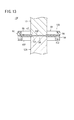
[第6実施形態]
次に、図12A〜図13を参照し、第6実施形態に係るピストン組立体10Fについて説明する。なお、第6実施形態に係るピストン組立体10Fにおいて、第1及び第4実施形態に係るピストン組立体10A、10Dと同一の構成要素には同一の参照符号を付し、詳細な説明を省略する。
[Sixth Embodiment]
Next, a
第6実施形態に係るピストン組立体10Fは、第4実施形態に係るピストン組立体10Dに対して、さらに、第3ピストン部材122及び第2ピストンロッド124を備えたものである。すなわち、本実施形態では、第1ピストン部材84、第2ピストン部材86及び第3ピストン部材122により、ピストン本体120が構成されているとともに、ピストン本体120を挟んでピストンロッド15とは反対側に第2ピストンロッド124が配置されている。以下、本実施形態において、ピストンロッド15を「第1ピストンロッド15」とよぶ。
The
第3ピストン部材122は、円形の基部126と、基部126の周縁の全周から軸線方向に延出した円筒形状の側周壁部128と、側周壁部128の端部(第2ピストン部材86を基準としてピストンロッドとは反対側の端部)から全周にわたって半径方向外方に広がるフランジ部130とを有する。基部126の中央には円形の貫通孔131が板厚方向に貫通形成されている。
The
図12Bに示すように、溶接によって第2ピストン部材86と接合される前の第3ピストン部材122には、第2ピストン部材86と接合する側の面に複数(図示例では、4つ)の溶接用突起129が設けられている。図示した第3ピストン部材122では、溶接用突起129は、周方向に等間隔に設けられている。第3ピストン部材122の貫通孔131は、第1ピストン部材84の貫通孔47と同一径である。
As shown in FIG. 12B, the
第3ピストン部材122のフランジ部130の輪郭の形状及び大きさと、第2ピストン部材86の輪郭の形状及び大きさは、同じまたは略同じである。図12Aに示すように、第2ピストン部材86の外周縁部と、第3ピストン部材122の側周壁部128と、フランジ部130とにより、周方向に360°の範囲で延在する溝部132が形成されている。
The shape and size of the contour of the
本実施形態において、第1ピストン部材84、第2ピストン部材86及び第3ピストン部材122は、非磁性体の金属により構成されている。このような非磁性体としては、アルミニウム合金、銅合金、亜鉛合金、ステンレス鋼等が挙げられる。
In the present embodiment, the
第2ピストンロッド124は、第1ピストンロッド15と同様に構成されている。すなわち、第2ピストンロッド124は、胴体部134と、胴体部134の基端に設けられた嵌合部136とを有する。ピストン本体120と溶接する前の第2ピストンロッド124には、溶接用突起138が設けられている。胴体部134、嵌合部136及び溶接用突起138は、それぞれ、第1ピストンロッド15における胴体部54、嵌合部56及び溶接用突起58(図3C参照)と同様に構成されている。
The
このようなピストン組立体10Fを製作するには、上述した第1実施形態に係るピストン組立体10Aと同様に、まず、第1ピストン部材84と第2ピストン部材86とをプロジェクション溶接により接合する。次に、第2ピストン部材86(第1ピストン部材84と接合された第2ピストン部材86)と第3ピストン部材122とをプロジェクション溶接により接合する。この場合、具体的には、第2ピストン部材86と第3ピストン部材122とを同心に重ね合わせて加圧した状態で、両部材に通電する。
In order to manufacture such a
そうすると、第3ピストン部材122に設けられた溶接用突起129が抵抗加熱によって溶融することで、第2ピストン部材86と第3ピストン部材122とが互いに接合される。これにより、第1ピストン部材84、第2ピストン部材86及び第3ピストン部材122からなるピストン本体120が製作される。なお、第2ピストン部材86と第3ピストン部材122とを接合した後に、第1ピストン部材84と第2ピストン部材86とを接合してもよい。
Then, the
次に、ピストン本体120と第1ピストンロッド15とをプロジェクション溶接によって互いに接合するとともに、ピストン本体120と第2ピストンロッド124とをプロジェクション溶接によって互いに接合する。ピストン本体120と第1ピストンロッド15との溶接は、第1実施形態におけるピストン本体13とピストンロッド15とを溶接する方法に準じて行うことができる。
Next, the
ピストン本体120と第2ピストンロッド124とを接合するには、まず、第2ピストンロッド124の基端をピストン本体120に突き合わせる。すなわち、第3ピストン部材122に設けられた貫通孔131に第2ピストンロッド124の基端に設けられた嵌合部136を嵌合させる。これにより、ピストン本体120に対する第2ピストンロッド124の位置決めを容易かつ精度よく行うことができる。またこのとき、第2ピストンロッド124に設けられた溶接用突起138が、第2ピストン部材86に当接する。
In order to join the piston
そして、第2ピストンロッド124とピストン本体120とを軸線方向に加圧した状態で、両者に通電する。そうすると、第2ピストンロッド124に設けられた溶接用突起138が抵抗加熱によって溶融することで、図13に示すように、ピストン本体120(第2ピストン部材86)と第2ピストンロッド124とが互いに接合される。これにより、第1ピストン部材84、第2ピストン部材86、第3ピストン部材122、第1ピストンロッド15及び第2ピストンロッド124からなるピストン組立体10Fが得られる。
And in the state which pressurized the
なお、ピストン本体120と第1ピストンロッド15との溶接を実施するタイミングと、ピストン本体120と第2ピストンロッド124との溶接を実施するタイミングは、いずれが先でもよく、あるいは同時であってもよい。
It should be noted that the timing at which the piston
なお、前記第2ピストン部材86に溶接用突起44を設けることなく第1ピストン部材84と第2ピストン部材86とを接着剤により接合して一体化してもよい。前記第3ピストン部材122に溶接用突起129を設けることなく第2ピストン部材86と第3ピストン部材122とを接着剤により接合して一体化してもよい。前記第1ピストンロッド15に溶接用突起58を設けることなくピストンロッド15とピストン本体120とを接着剤により接合して一体化してもよい。前記第2ピストンロッド124に溶接用突起138を設けることなく第2ピストンロッド124とピストン本体120とを接着剤により接合して一体化してもよい。
Note that the
図13に示すように、ピストン組立体10Fのピストン本体120の外周部(シール装着溝96)には、リング状のシール部材98が装着され、溝部132には、マグネット(永久磁石)140が配置される。マグネット140は、炭素鋼、コバルト鋼、アルニコ、合成ゴム、またはその他の材料を用いて形成されたものである。マグネット140は、リング状でもよく、あるいは、周方向に複数に分割されたものであってもよい。マグネット140がリング状の場合、第2ピストン部材86と第3ピストン部材122とを接合する前に、第3ピストン部材122の側周壁部128にマグネット140が装着される。
As shown in FIG. 13, a ring-shaped
シール部材98及びマグネット140が装着されたピストン組立体10Fは、断面円形の摺動孔を有するハウジング内に摺動可能に配置されて、流体圧シリンダとして組み立てられる。この場合、前記ハウジングの外面には、ピストン本体120のストローク両端に相当する位置に磁気センサが取り付けられ、マグネット140が発生する磁気を前記磁気センサによって感知することで、ピストン本体120の動作位置が検出される。
The
本実施形態に係るピストン組立体10Fは、第1ピストンロッド15及び第2ピストンロッド124を有する「ダブルロッド型」の構成であるが、従来のダブルロッド型のピストン組立体と比較して、ピストン本体120の幅(軸線方向の厚さ)を短くすることが可能である。よって、ピストン組立体10Fの全長を短くすることができ、装置全体の小型化が可能となり、コストダウンを図ることができる。
The
その他、第6実施形態に係るピストン組立体10Fによっても、第1実施形態に係るピストン組立体10Aと同様の作用効果が得られる。
In addition, the
なお、ピストン組立体10Fの変形例として、第2ピストンロッド124を無くした形態を採用してもよい。また、ピストン組立体10Fの別の変形例として、ピストン本体120を、第1実施形態のピストン本体13と同様の長円形状の構成としてもよく、あるいは楕円形状としてもよい。
In addition, you may employ | adopt the form which eliminated the
ピストン組立体10Fでは、第1ピストン部材84と第2ピストン部材86との間にシール部材98が配置されるとともに、第2ピストン部材86と第3ピストン部材122との間にマグネット140が配置されたが、シール部材98とマグネット140の配置を逆にしてもよい。すなわち、第1ピストン部材84と第2ピストン部材86との間にマグネット140が配置されるとともに、第2ピストン部材86と第3ピストン部材122との間にシール部材98が配置されてもよい。
In the piston assembly 10 </ b> F, a
[その他の変形例]
上述した実施形態では、ピストン組立体10A〜10Fの各構成要素は、プロジェクション溶接により接合されたが、本発明はこれに限らず、プロジェクション溶接以外の溶接方法によってピストン組立体10A〜10Fの各構成要素が接合されてもよい。
[Other variations]
In the above-described embodiment, the components of the
上記において、本発明について好適な実施形態を挙げて説明したが、本発明は前記実施形態に限定されるものではなく、本発明の要旨を逸脱しない範囲において、種々の改変が可能なことは言うまでもない。 In the above description, the present invention has been described with reference to preferred embodiments. However, the present invention is not limited to the above-described embodiments, and various modifications can be made without departing from the scope of the present invention. Yes.
10A〜10F…ピストン組立体
13、60、80、88、100、120…ピストン本体
15…ピストンロッド(第1ピストンロッド)
40、62、82、84…第1ピストン部材
42、64、86…第2ピストン部材 47、131…貫通孔
56、136…嵌合部 106、122…第3ピストン部材
116、132…溝部 118…ウエアリング
124…第2ピストンロッド 140…マグネット
10A to 10F:
40, 62, 82, 84 ...
Claims (8)
前記ピストン本体に接合されたピストンロッドと、を備え、
前記ピストン本体は、板状部材により構成された第1ピストン部材と第2ピストン部材とを有し、
前記第1ピストン部材と前記第2ピストン部材とは、前記ピストンロッドの軸線方向に重ねた状態で、互いに接合されており、
前記第1ピストン部材の外周縁部と前記第2ピストン部材の外周縁部との間に周方向に延在するシール装着溝が形成され、
前記第1ピストン部材と前記第2ピストン部材のうち少なくとも一方は、全体にわたって板厚を有する、
ことを特徴とするピストン組立体。 A piston body;
A piston rod joined to the piston body,
The piston body has a first piston member and a second piston member constituted by plate-like members,
The first piston member and the second piston member are joined to each other in a state of being overlapped in the axial direction of the piston rod,
A seal mounting groove extending in the circumferential direction is formed between the outer peripheral edge of the first piston member and the outer peripheral edge of the second piston member,
At least one of the first piston member and the second piston member has a plate thickness throughout.
A piston assembly characterized by that.
前記第1ピストン部材には、板厚方向の貫通孔が設けられ、
前記ピストンロッドの一端には、前記貫通孔に嵌合する嵌合部が突出形成されている、
ことを特徴とするピストン組立体。 The piston assembly of claim 1, wherein
The first piston member is provided with a through-hole in the thickness direction,
At one end of the piston rod, a fitting part that fits into the through hole is formed to protrude.
A piston assembly characterized by that.
前記ピストン本体は、板状部材により構成された第3ピストン部材を有し、
前記ピストン本体の外周部で、前記第2ピストン部材と前記第3ピストン部材との間に形成される溝部に、前記ピストン本体の外周に沿って延在するサポート部材又はマグネットが配設されている、
ことを特徴とするピストン組立体。 The piston assembly of claim 1, wherein
The piston body has a third piston member constituted by a plate-like member,
A support member or a magnet extending along the outer periphery of the piston body is disposed in a groove formed between the second piston member and the third piston member at the outer periphery of the piston body . ,
A piston assembly characterized by that.
前記ピストン本体の一方の側に、第1ピストンロッドとしての前記ピストンロッドが溶接により接合され、
前記ピストン本体の他方の側に、第2ピストンロッドが接合されている、
ことを特徴とするピストン組立体。 The piston assembly according to any one of claims 1 to 3,
The piston rod as the first piston rod is joined to one side of the piston body by welding,
A second piston rod is joined to the other side of the piston body;
A piston assembly characterized by that.
前記第1ピストン部材と前記第2ピストン部材とは、溶接によって接合され、
前記ピストン本体と前記ピストンロッドとは、溶接によって接合されている、
ことを特徴とするピストン組立体。 The piston assembly according to any one of claims 1 to 4,
The first piston member and the second piston member are joined by welding,
The piston body and the piston rod are joined by welding,
A piston assembly characterized by that.
前記ピストン組立体を軸線方向に移動可能に収容するハウジングと、を備える、
ことを特徴とする流体圧シリンダ。 The piston assembly according to any one of claims 1 to 5,
A housing for accommodating the piston assembly movably in the axial direction,
A fluid pressure cylinder characterized by that.
前記ピストン本体とピストンロッドとを接合する第2工程と、を有し、
前記第1ピストン部材の外周縁部と前記第2ピストン部材の外周縁部との間に周方向に延在するシール装着溝が形成され、
前記第1ピストン部材と前記第2ピストン部材のうち少なくとも一方は、全体にわたって板厚を有する、
ことを特徴とするピストン組立体の製造方法。 A first step in which a first piston member and a second piston member constituted by plate-like members are overlapped and joined together to obtain a piston body;
A second step of joining the piston body and the piston rod,
A seal mounting groove extending in the circumferential direction is formed between the outer peripheral edge of the first piston member and the outer peripheral edge of the second piston member,
At least one of the first piston member and the second piston member has a plate thickness throughout.
A method for manufacturing a piston assembly.
前記第1工程において、前記第1ピストン部材と前記第2ピストン部材とを溶接によって接合し、
前記第2工程において、前記ピストン本体と前記ピストンロッドとを溶接によって接合する、
ことを特徴とするピストン組立体の製造方法。 In the manufacturing method of the piston assembly according to claim 7,
In the first step, the first piston member and the second piston member are joined by welding,
In the second step, the piston body and the piston rod are joined by welding,
A method for manufacturing a piston assembly.
Priority Applications (9)
| Application Number | Priority Date | Filing Date | Title |
|---|---|---|---|
| JP2011124756A JP5435434B2 (en) | 2011-06-03 | 2011-06-03 | Piston assembly, fluid pressure cylinder, and method of manufacturing piston assembly |
| BR112013031008-1A BR112013031008B1 (en) | 2011-06-03 | 2012-05-22 | piston assembly, fluid pressure cylinder, method for making piston assembly |
| KR1020137032122A KR101540949B1 (en) | 2011-06-03 | 2012-05-22 | Piston assembly, fluid pressure cylinder, method for manufacturing piston assembly |
| PCT/JP2012/063083 WO2012165232A1 (en) | 2011-06-03 | 2012-05-22 | Piston assembly, fluid pressure cylinder, method for manufacturing piston assembly |
| MX2013014127A MX349599B (en) | 2011-06-03 | 2012-05-22 | Piston assembly, fluid pressure cylinder, method for manufacturing piston assembly. |
| EP12792299.5A EP2716920B1 (en) | 2011-06-03 | 2012-05-22 | Piston assembly, fluid pressure cylinder, method for manufacturing piston assembly |
| US14/122,902 US9765800B2 (en) | 2011-06-03 | 2012-05-22 | Piston assembly, fluid pressure cylinder, method for manufacturing piston assembly |
| CN201280026561.8A CN103620234B (en) | 2011-06-03 | 2012-05-22 | Piston assembling body, fluid pressure cylinder, for the manufacture of the method for Piston assembling body |
| TW101119287A TWI453352B (en) | 2011-06-03 | 2012-05-30 | Piston assembly, fluid pressure cylinder, and method for manufacturing the piston assembly |
Applications Claiming Priority (1)
| Application Number | Priority Date | Filing Date | Title |
|---|---|---|---|
| JP2011124756A JP5435434B2 (en) | 2011-06-03 | 2011-06-03 | Piston assembly, fluid pressure cylinder, and method of manufacturing piston assembly |
Publications (3)
| Publication Number | Publication Date |
|---|---|
| JP2012251602A JP2012251602A (en) | 2012-12-20 |
| JP2012251602A5 JP2012251602A5 (en) | 2013-03-21 |
| JP5435434B2 true JP5435434B2 (en) | 2014-03-05 |
Family
ID=47259093
Family Applications (1)
| Application Number | Title | Priority Date | Filing Date |
|---|---|---|---|
| JP2011124756A Active JP5435434B2 (en) | 2011-06-03 | 2011-06-03 | Piston assembly, fluid pressure cylinder, and method of manufacturing piston assembly |
Country Status (9)
| Country | Link |
|---|---|
| US (1) | US9765800B2 (en) |
| EP (1) | EP2716920B1 (en) |
| JP (1) | JP5435434B2 (en) |
| KR (1) | KR101540949B1 (en) |
| CN (1) | CN103620234B (en) |
| BR (1) | BR112013031008B1 (en) |
| MX (1) | MX349599B (en) |
| TW (1) | TWI453352B (en) |
| WO (1) | WO2012165232A1 (en) |
Cited By (3)
| Publication number | Priority date | Publication date | Assignee | Title |
|---|---|---|---|---|
| US10718360B2 (en) | 2016-08-10 | 2020-07-21 | Smc Corporation | Hydraulic fluid device |
| US10851813B2 (en) | 2016-08-10 | 2020-12-01 | Smc Corporation | Method for producing piston assembly and hydraulic fluid device |
| US11280409B2 (en) | 2016-08-10 | 2022-03-22 | Smc Corporation | Method for producing piston assembly and hydraulic fluid device |
Families Citing this family (17)
| Publication number | Priority date | Publication date | Assignee | Title |
|---|---|---|---|---|
| DE102013008408A1 (en) * | 2013-05-16 | 2014-11-20 | Festo Ag & Co. Kg | Drive unit of a fluid-actuated linear drive and method for its production |
| JP5916139B2 (en) * | 2013-07-26 | 2016-05-11 | 株式会社鷺宮製作所 | Fixing method of connecting fitting and piston in four-way switching valve and welding method of fixing screw in four-way switching valve |
| CN107000720B (en) * | 2014-12-03 | 2019-08-09 | 纽约气闸有限公司 | Improved brake piston component |
| US10035526B2 (en) | 2014-12-03 | 2018-07-31 | New York Air Brake, LLC | Brake piston assembly |
| US11148338B2 (en) | 2015-03-24 | 2021-10-19 | Dorothy Feibleman | Devices, systems, and methods for extruding materials bearing millefiori-like patterns |
| US10598283B2 (en) * | 2015-03-24 | 2020-03-24 | Dorothy Feibleman | Extrusion seal devices and methods |
| JP6252952B2 (en) * | 2015-05-11 | 2017-12-27 | Smc株式会社 | Rotary actuator |
| JP6403072B2 (en) | 2015-06-11 | 2018-10-10 | Smc株式会社 | Fluid pressure cylinder |
| JP6403071B2 (en) * | 2015-06-11 | 2018-10-10 | Smc株式会社 | Fluid pressure cylinder |
| JP6519864B2 (en) | 2015-06-11 | 2019-05-29 | Smc株式会社 | Fluid pressure cylinder |
| JP6519865B2 (en) | 2015-06-11 | 2019-05-29 | Smc株式会社 | Fluid pressure cylinder |
| JP6292483B2 (en) | 2015-06-11 | 2018-03-14 | Smc株式会社 | Fluid pressure cylinder |
| JP6403073B2 (en) | 2015-06-11 | 2018-10-10 | Smc株式会社 | Fluid pressure cylinder |
| DE102016112861A1 (en) * | 2016-07-13 | 2018-01-18 | Newfrey Llc | Joining head and joining robot with reduced interference contour |
| KR102012656B1 (en) * | 2017-08-14 | 2019-08-21 | 주식회사 크로시스 | Piston for Energy Recovery Device of Reverse Osmosis Desalination Systems |
| CN109175744A (en) * | 2018-10-15 | 2019-01-11 | 仪征常众汽车部件有限公司 | A kind of welding procedure for cooler bin in New-energy electric vehicle |
| WO2021144964A1 (en) | 2020-01-17 | 2021-07-22 | 株式会社Olive Union | Hearing device, and method for adjusting hearing device |
Family Cites Families (37)
| Publication number | Priority date | Publication date | Assignee | Title |
|---|---|---|---|---|
| US48851A (en) * | 1865-07-18 | Improvement in pistons for steam-engines | ||
| GB366781A (en) | 1931-03-23 | 1932-02-11 | Clement Henry Stevens | Improvements in pistons for reciprocating engines, pumps, and the like |
| CH204322A (en) * | 1938-06-03 | 1939-04-30 | Rickenbach Oskar | Piston with sleeve seal. |
| US2878085A (en) * | 1955-08-01 | 1959-03-17 | George E Barnhart | Flexible sealing ring arrangement |
| US3171334A (en) * | 1963-07-05 | 1965-03-02 | Honeywell Inc | Control apparatus |
| US3752367A (en) * | 1972-06-26 | 1973-08-14 | E Sundholm | Plunger assembly for hand-operated grease gun |
| US4370918A (en) * | 1980-03-24 | 1983-02-01 | Pringle William L | Fluid cylinder assembly |
| JPS58123957A (en) * | 1982-01-16 | 1983-07-23 | 荻野 初太郎 | Cushion, heat insulating and sheet waterproofing execution of concrete floor panel in rooftop or roof |
| JPS58123957U (en) | 1982-02-17 | 1983-08-23 | 自動車機器株式会社 | piston |
| DE8507230U1 (en) * | 1985-03-09 | 1985-04-25 | Lange, Jörg, 8607 Hollfeld | Hydraulic cylinder with quick reset option |
| JPS634406A (en) | 1986-06-25 | 1988-01-09 | Toshiba Corp | Magnetic head |
| JPS634406U (en) | 1986-06-26 | 1988-01-12 | ||
| US5213025A (en) * | 1990-01-26 | 1993-05-25 | Thomas Industries Inc. | Conical rod piston |
| US5022312A (en) * | 1990-01-26 | 1991-06-11 | Thomas Industries | Plastic piston head assembly |
| JPH0418704U (en) * | 1990-06-07 | 1992-02-17 | ||
| JP2645787B2 (en) * | 1993-01-26 | 1997-08-25 | 株式会社ユタカ技研 | Circumferential groove forming method |
| JPH0828703A (en) * | 1994-07-22 | 1996-02-02 | Fujikura Rubber Ltd | Energizing controller for moving body |
| JP3822259B2 (en) * | 1995-01-17 | 2006-09-13 | Smc株式会社 | Cylinder device |
| JPH0942217A (en) * | 1995-07-25 | 1997-02-10 | Calsonic Corp | Cylinder type actuator |
| JP3780043B2 (en) * | 1996-10-09 | 2006-05-31 | Smc株式会社 | Cylinder device |
| US5680913A (en) * | 1996-11-22 | 1997-10-28 | Caterpillar Inc. | Snubber for a hydraulic motor |
| JP3390144B2 (en) * | 1999-02-25 | 2003-03-24 | エスエムシー株式会社 | Fluid pressure cylinder with lock mechanism |
| US6499384B1 (en) * | 2000-11-28 | 2002-12-31 | Jim S. Blair | Piston apparatus for gas/liquid pipeline |
| US6525289B2 (en) * | 2001-02-01 | 2003-02-25 | Delphi Technologies, Inc. | Piston for magneto-rheological fluid systems and method for its manufacture |
| US7281502B2 (en) * | 2003-04-24 | 2007-10-16 | Team Holdings (Uk) Limited | Powered devices |
| EP1658434A4 (en) | 2003-07-25 | 2010-07-21 | Lg Electronics Inc | Pistion assembly of cooler |
| CN2727505Y (en) * | 2004-08-03 | 2005-09-21 | 辛学慧 | Built up thin piston |
| DE202006000861U1 (en) * | 2006-01-19 | 2006-03-16 | Chen, Chi-Ming, Sindian | Piston for pneumatic pump has a flat plate with an integral valve flap secured by a clamping strip and with a profiled outer sealing ring |
| CN2895899Y (en) * | 2006-03-31 | 2007-05-02 | 苏人杰 | Gas-oil cylinder piston structure |
| CN201016390Y (en) | 2006-11-24 | 2008-02-06 | 凃振兴 | Piston structure improvement of metal extrusion press oil-hydraulic cylinder |
| JP4737453B2 (en) * | 2006-12-06 | 2011-08-03 | Smc株式会社 | Fluid pressure cylinder |
| JP4587107B2 (en) * | 2007-03-28 | 2010-11-24 | Smc株式会社 | Piston assembly in a hydraulic cylinder |
| DE102007045892B4 (en) * | 2007-09-25 | 2013-04-04 | Thyssenkrupp Bilstein Suspension Gmbh | Vibration damper with a cable stop |
| CN201250819Y (en) * | 2008-06-05 | 2009-06-03 | 广州珠江钢铁有限责任公司 | Oil cylinder and piston and piston rod connection structure employed by same |
| GB0812903D0 (en) | 2008-07-15 | 2008-08-20 | Rota Eng Ltd | Linear actuator and position sensing apparatus therefor |
| CN201359079Y (en) * | 2009-03-06 | 2009-12-09 | 徐州徐工液压件有限公司 | Welded-type piston component for finished products |
| CN201763942U (en) * | 2010-09-25 | 2011-03-16 | 浙江龙文机械有限责任公司 | Air cylinder piston |
-
2011
- 2011-06-03 JP JP2011124756A patent/JP5435434B2/en active Active
-
2012
- 2012-05-22 WO PCT/JP2012/063083 patent/WO2012165232A1/en active Application Filing
- 2012-05-22 BR BR112013031008-1A patent/BR112013031008B1/en not_active IP Right Cessation
- 2012-05-22 EP EP12792299.5A patent/EP2716920B1/en not_active Not-in-force
- 2012-05-22 CN CN201280026561.8A patent/CN103620234B/en not_active Expired - Fee Related
- 2012-05-22 MX MX2013014127A patent/MX349599B/en active IP Right Grant
- 2012-05-22 US US14/122,902 patent/US9765800B2/en active Active
- 2012-05-22 KR KR1020137032122A patent/KR101540949B1/en active IP Right Grant
- 2012-05-30 TW TW101119287A patent/TWI453352B/en not_active IP Right Cessation
Cited By (3)
| Publication number | Priority date | Publication date | Assignee | Title |
|---|---|---|---|---|
| US10718360B2 (en) | 2016-08-10 | 2020-07-21 | Smc Corporation | Hydraulic fluid device |
| US10851813B2 (en) | 2016-08-10 | 2020-12-01 | Smc Corporation | Method for producing piston assembly and hydraulic fluid device |
| US11280409B2 (en) | 2016-08-10 | 2022-03-22 | Smc Corporation | Method for producing piston assembly and hydraulic fluid device |
Also Published As
| Publication number | Publication date |
|---|---|
| JP2012251602A (en) | 2012-12-20 |
| MX349599B (en) | 2017-08-04 |
| KR101540949B1 (en) | 2015-07-31 |
| CN103620234A (en) | 2014-03-05 |
| US20140076157A1 (en) | 2014-03-20 |
| EP2716920A1 (en) | 2014-04-09 |
| KR20140010165A (en) | 2014-01-23 |
| MX2013014127A (en) | 2014-07-09 |
| BR112013031008A2 (en) | 2016-12-13 |
| WO2012165232A1 (en) | 2012-12-06 |
| EP2716920A4 (en) | 2015-05-20 |
| TW201309947A (en) | 2013-03-01 |
| CN103620234B (en) | 2016-05-25 |
| BR112013031008B1 (en) | 2021-01-26 |
| EP2716920B1 (en) | 2017-03-22 |
| US9765800B2 (en) | 2017-09-19 |
| TWI453352B (en) | 2014-09-21 |
Similar Documents
| Publication | Publication Date | Title |
|---|---|---|
| JP5435434B2 (en) | Piston assembly, fluid pressure cylinder, and method of manufacturing piston assembly | |
| US10851813B2 (en) | Method for producing piston assembly and hydraulic fluid device | |
| JP6519865B2 (en) | Fluid pressure cylinder | |
| US20170298931A1 (en) | Fluidic cylinder | |
| US10718360B2 (en) | Hydraulic fluid device | |
| WO2018030014A1 (en) | Method for producing piston assembly and hydraulic fluid device | |
| JP2017115905A (en) | Fluid cylinder with sensor | |
| TWI605200B (en) | Fluid pressure cylinder | |
| US10662981B2 (en) | Fluid pressure cylinder |
Legal Events
| Date | Code | Title | Description |
|---|---|---|---|
| A521 | Request for written amendment filed |
Free format text: JAPANESE INTERMEDIATE CODE: A523 Effective date: 20130205 |
|
| A621 | Written request for application examination |
Free format text: JAPANESE INTERMEDIATE CODE: A621 Effective date: 20130205 |
|
| TRDD | Decision of grant or rejection written | ||
| A01 | Written decision to grant a patent or to grant a registration (utility model) |
Free format text: JAPANESE INTERMEDIATE CODE: A01 Effective date: 20131112 |
|
| A61 | First payment of annual fees (during grant procedure) |
Free format text: JAPANESE INTERMEDIATE CODE: A61 Effective date: 20131202 |
|
| R150 | Certificate of patent or registration of utility model |
Ref document number: 5435434 Country of ref document: JP Free format text: JAPANESE INTERMEDIATE CODE: R150 Free format text: JAPANESE INTERMEDIATE CODE: R150 |
|
| R250 | Receipt of annual fees |
Free format text: JAPANESE INTERMEDIATE CODE: R250 |
|
| R250 | Receipt of annual fees |
Free format text: JAPANESE INTERMEDIATE CODE: R250 |
|
| R250 | Receipt of annual fees |
Free format text: JAPANESE INTERMEDIATE CODE: R250 |
|
| R250 | Receipt of annual fees |
Free format text: JAPANESE INTERMEDIATE CODE: R250 |
|
| R250 | Receipt of annual fees |
Free format text: JAPANESE INTERMEDIATE CODE: R250 |
|
| R250 | Receipt of annual fees |
Free format text: JAPANESE INTERMEDIATE CODE: R250 |
|
| R250 | Receipt of annual fees |
Free format text: JAPANESE INTERMEDIATE CODE: R250 |
|
| R250 | Receipt of annual fees |
Free format text: JAPANESE INTERMEDIATE CODE: R250 |