WO2012165187A1 - 試料処理装置、試料処理方法、およびこれらに使用する反応容器 - Google Patents
試料処理装置、試料処理方法、およびこれらに使用する反応容器 Download PDFInfo
- Publication number
- WO2012165187A1 WO2012165187A1 PCT/JP2012/062891 JP2012062891W WO2012165187A1 WO 2012165187 A1 WO2012165187 A1 WO 2012165187A1 JP 2012062891 W JP2012062891 W JP 2012062891W WO 2012165187 A1 WO2012165187 A1 WO 2012165187A1
- Authority
- WO
- WIPO (PCT)
- Prior art keywords
- stem
- reaction vessel
- cover
- reaction
- magnetic
- Prior art date
Links
Images


Classifications
-
- C—CHEMISTRY; METALLURGY
- C12—BIOCHEMISTRY; BEER; SPIRITS; WINE; VINEGAR; MICROBIOLOGY; ENZYMOLOGY; MUTATION OR GENETIC ENGINEERING
- C12N—MICROORGANISMS OR ENZYMES; COMPOSITIONS THEREOF; PROPAGATING, PRESERVING, OR MAINTAINING MICROORGANISMS; MUTATION OR GENETIC ENGINEERING; CULTURE MEDIA
- C12N15/00—Mutation or genetic engineering; DNA or RNA concerning genetic engineering, vectors, e.g. plasmids, or their isolation, preparation or purification; Use of hosts therefor
- C12N15/09—Recombinant DNA-technology
- C12N15/10—Processes for the isolation, preparation or purification of DNA or RNA
- C12N15/1003—Extracting or separating nucleic acids from biological samples, e.g. pure separation or isolation methods; Conditions, buffers or apparatuses therefor
- C12N15/1006—Extracting or separating nucleic acids from biological samples, e.g. pure separation or isolation methods; Conditions, buffers or apparatuses therefor by means of a solid support carrier, e.g. particles, polymers
- C12N15/1013—Extracting or separating nucleic acids from biological samples, e.g. pure separation or isolation methods; Conditions, buffers or apparatuses therefor by means of a solid support carrier, e.g. particles, polymers by using magnetic beads
-
- B—PERFORMING OPERATIONS; TRANSPORTING
- B03—SEPARATION OF SOLID MATERIALS USING LIQUIDS OR USING PNEUMATIC TABLES OR JIGS; MAGNETIC OR ELECTROSTATIC SEPARATION OF SOLID MATERIALS FROM SOLID MATERIALS OR FLUIDS; SEPARATION BY HIGH-VOLTAGE ELECTRIC FIELDS
- B03C—MAGNETIC OR ELECTROSTATIC SEPARATION OF SOLID MATERIALS FROM SOLID MATERIALS OR FLUIDS; SEPARATION BY HIGH-VOLTAGE ELECTRIC FIELDS
- B03C1/00—Magnetic separation
- B03C1/02—Magnetic separation acting directly on the substance being separated
- B03C1/025—High gradient magnetic separators
- B03C1/031—Component parts; Auxiliary operations
- B03C1/033—Component parts; Auxiliary operations characterised by the magnetic circuit
- B03C1/0332—Component parts; Auxiliary operations characterised by the magnetic circuit using permanent magnets
-
- B—PERFORMING OPERATIONS; TRANSPORTING
- B03—SEPARATION OF SOLID MATERIALS USING LIQUIDS OR USING PNEUMATIC TABLES OR JIGS; MAGNETIC OR ELECTROSTATIC SEPARATION OF SOLID MATERIALS FROM SOLID MATERIALS OR FLUIDS; SEPARATION BY HIGH-VOLTAGE ELECTRIC FIELDS
- B03C—MAGNETIC OR ELECTROSTATIC SEPARATION OF SOLID MATERIALS FROM SOLID MATERIALS OR FLUIDS; SEPARATION BY HIGH-VOLTAGE ELECTRIC FIELDS
- B03C1/00—Magnetic separation
- B03C1/02—Magnetic separation acting directly on the substance being separated
- B03C1/28—Magnetic plugs and dipsticks
- B03C1/284—Magnetic plugs and dipsticks with associated cleaning means, e.g. retractable non-magnetic sleeve
-
- B—PERFORMING OPERATIONS; TRANSPORTING
- B03—SEPARATION OF SOLID MATERIALS USING LIQUIDS OR USING PNEUMATIC TABLES OR JIGS; MAGNETIC OR ELECTROSTATIC SEPARATION OF SOLID MATERIALS FROM SOLID MATERIALS OR FLUIDS; SEPARATION BY HIGH-VOLTAGE ELECTRIC FIELDS
- B03C—MAGNETIC OR ELECTROSTATIC SEPARATION OF SOLID MATERIALS FROM SOLID MATERIALS OR FLUIDS; SEPARATION BY HIGH-VOLTAGE ELECTRIC FIELDS
- B03C1/00—Magnetic separation
- B03C1/02—Magnetic separation acting directly on the substance being separated
- B03C1/28—Magnetic plugs and dipsticks
- B03C1/286—Magnetic plugs and dipsticks disposed at the inner circumference of a recipient, e.g. magnetic drain bolt
-
- G—PHYSICS
- G01—MEASURING; TESTING
- G01N—INVESTIGATING OR ANALYSING MATERIALS BY DETERMINING THEIR CHEMICAL OR PHYSICAL PROPERTIES
- G01N35/00—Automatic analysis not limited to methods or materials provided for in any single one of groups G01N1/00 - G01N33/00; Handling materials therefor
- G01N35/0099—Automatic analysis not limited to methods or materials provided for in any single one of groups G01N1/00 - G01N33/00; Handling materials therefor comprising robots or similar manipulators
-
- G—PHYSICS
- G01—MEASURING; TESTING
- G01N—INVESTIGATING OR ANALYSING MATERIALS BY DETERMINING THEIR CHEMICAL OR PHYSICAL PROPERTIES
- G01N35/00—Automatic analysis not limited to methods or materials provided for in any single one of groups G01N1/00 - G01N33/00; Handling materials therefor
- G01N35/02—Automatic analysis not limited to methods or materials provided for in any single one of groups G01N1/00 - G01N33/00; Handling materials therefor using a plurality of sample containers moved by a conveyor system past one or more treatment or analysis stations
- G01N35/026—Automatic analysis not limited to methods or materials provided for in any single one of groups G01N1/00 - G01N33/00; Handling materials therefor using a plurality of sample containers moved by a conveyor system past one or more treatment or analysis stations having blocks or racks of reaction cells or cuvettes
-
- G—PHYSICS
- G01—MEASURING; TESTING
- G01N—INVESTIGATING OR ANALYSING MATERIALS BY DETERMINING THEIR CHEMICAL OR PHYSICAL PROPERTIES
- G01N35/00—Automatic analysis not limited to methods or materials provided for in any single one of groups G01N1/00 - G01N33/00; Handling materials therefor
- G01N35/10—Devices for transferring samples or any liquids to, in, or from, the analysis apparatus, e.g. suction devices, injection devices
- G01N35/1081—Devices for transferring samples or any liquids to, in, or from, the analysis apparatus, e.g. suction devices, injection devices characterised by the means for relatively moving the transfer device and the containers in an horizontal plane
- G01N35/109—Devices for transferring samples or any liquids to, in, or from, the analysis apparatus, e.g. suction devices, injection devices characterised by the means for relatively moving the transfer device and the containers in an horizontal plane with two horizontal degrees of freedom
-
- B—PERFORMING OPERATIONS; TRANSPORTING
- B03—SEPARATION OF SOLID MATERIALS USING LIQUIDS OR USING PNEUMATIC TABLES OR JIGS; MAGNETIC OR ELECTROSTATIC SEPARATION OF SOLID MATERIALS FROM SOLID MATERIALS OR FLUIDS; SEPARATION BY HIGH-VOLTAGE ELECTRIC FIELDS
- B03C—MAGNETIC OR ELECTROSTATIC SEPARATION OF SOLID MATERIALS FROM SOLID MATERIALS OR FLUIDS; SEPARATION BY HIGH-VOLTAGE ELECTRIC FIELDS
- B03C2201/00—Details of magnetic or electrostatic separation
- B03C2201/18—Magnetic separation whereby the particles are suspended in a liquid
-
- B—PERFORMING OPERATIONS; TRANSPORTING
- B03—SEPARATION OF SOLID MATERIALS USING LIQUIDS OR USING PNEUMATIC TABLES OR JIGS; MAGNETIC OR ELECTROSTATIC SEPARATION OF SOLID MATERIALS FROM SOLID MATERIALS OR FLUIDS; SEPARATION BY HIGH-VOLTAGE ELECTRIC FIELDS
- B03C—MAGNETIC OR ELECTROSTATIC SEPARATION OF SOLID MATERIALS FROM SOLID MATERIALS OR FLUIDS; SEPARATION BY HIGH-VOLTAGE ELECTRIC FIELDS
- B03C2201/00—Details of magnetic or electrostatic separation
- B03C2201/26—Details of magnetic or electrostatic separation for use in medical applications
-
- B—PERFORMING OPERATIONS; TRANSPORTING
- B03—SEPARATION OF SOLID MATERIALS USING LIQUIDS OR USING PNEUMATIC TABLES OR JIGS; MAGNETIC OR ELECTROSTATIC SEPARATION OF SOLID MATERIALS FROM SOLID MATERIALS OR FLUIDS; SEPARATION BY HIGH-VOLTAGE ELECTRIC FIELDS
- B03C—MAGNETIC OR ELECTROSTATIC SEPARATION OF SOLID MATERIALS FROM SOLID MATERIALS OR FLUIDS; SEPARATION BY HIGH-VOLTAGE ELECTRIC FIELDS
- B03C2201/00—Details of magnetic or electrostatic separation
- B03C2201/28—Parts being easily removable for cleaning purposes
-
- G—PHYSICS
- G01—MEASURING; TESTING
- G01N—INVESTIGATING OR ANALYSING MATERIALS BY DETERMINING THEIR CHEMICAL OR PHYSICAL PROPERTIES
- G01N35/00—Automatic analysis not limited to methods or materials provided for in any single one of groups G01N1/00 - G01N33/00; Handling materials therefor
- G01N35/10—Devices for transferring samples or any liquids to, in, or from, the analysis apparatus, e.g. suction devices, injection devices
- G01N2035/1027—General features of the devices
- G01N2035/103—General features of the devices using disposable tips
-
- G—PHYSICS
- G01—MEASURING; TESTING
- G01N—INVESTIGATING OR ANALYSING MATERIALS BY DETERMINING THEIR CHEMICAL OR PHYSICAL PROPERTIES
- G01N35/00—Automatic analysis not limited to methods or materials provided for in any single one of groups G01N1/00 - G01N33/00; Handling materials therefor
- G01N35/10—Devices for transferring samples or any liquids to, in, or from, the analysis apparatus, e.g. suction devices, injection devices
- G01N35/1065—Multiple transfer devices
- G01N35/1067—Multiple transfer devices for transfer to or from containers having different spacing
Definitions
- the present invention relates to a sample processing apparatus and a sample processing method for extracting a biological molecule such as a nucleic acid or protein from a biological sample containing cells, bacteria, viruses, etc., or in addition to separating and purifying it. Furthermore, it is related with the reaction container used for these sample processing apparatuses and sample processing methods.
- PCR Polymerase® Chain Reaction
- SDA Strand-Displacement-Amplification
- 3SR Self-Sustained-Sequence-Replication
- TMA Transcription-Mediated-Amplification
- Q ⁇ -Replicase-Amplification method LAMP (Loop)
- nucleic acid amplification methods such as -mediated (isothermal) amplification)
- the application range of nucleic acid testing is expanding. Therefore, the need for techniques for extracting, separating, and purifying nucleic acids from biological samples more rapidly and simply will increase.
- a phenol / chloroform extraction method is known as a method for extracting, separating and purifying nucleic acids such as DNA and RNA from biological samples.
- this method has a heavy burden on the operator because of the use of an organic solvent and complicated operation. Therefore, in order to solve this problem, as a method for extracting, separating and purifying nucleic acid from a biological sample, a method utilizing the property of binding nucleic acid to silica or glass fiber in the presence of a chaotropic agent (for example, non-patent) Document 1) was proposed, and an apparatus for automatically performing nucleic acid extraction was also developed (for example, Patent Documents 1 and 2).
- a chaotropic agent for example, non-patent
- the flow of nucleic acid extraction, separation, and purification that is usually performed in an automatic apparatus is as follows (1) to (6).
- Patent Document 1 is a so-called batch process in which a plurality of samples are processed simultaneously when processing a plurality of samples, and does not continuously process samples provided randomly.
- the automated device described in Patent Document 2 is described as “installing a plurality of sets of extraction devices in the apparatus main body” when processing a plurality of samples, and a vertical movement mechanism of a plurality of arms; A large number of drive units such as a movement mechanism for a plurality of arm positions are required.
- Patent Document 2 also states that a plurality of sample containers can be mounted at the same time, but clearly states that they can be processed at the same time, and batch processing that performs the same operation by sharing the drive units of a plurality of extraction devices. In this case, too, a randomly provided specimen cannot be processed at any time.
- An object of the present invention is to batch process biological samples (for example, specimens) in an apparatus for reacting a biological sample with a reagent to perform a series of processing, or to perform random processing at random and continuous processing as needed.
- Another object of the present invention is to provide a sample processing apparatus, a sample processing method, and a reaction vessel used for these.
- sample processing apparatus 1 That is, a sample is provided with a reaction container in which a series of processes are performed by reacting a biological sample with a reagent, and the reaction container is provided with a plurality of processing units arranged to perform the series of processes.
- a reaction vessel set part capable of juxtaposing a plurality of the reaction vessels;
- a reaction vessel moving mechanism for moving the reaction vessel set in the reaction vessel set unit independently in the arrangement direction of the processing unit for each reaction vessel;
- a plurality of stems used for the series of processes in cooperation with the reaction vessel are arranged to be movable up and down above the reaction vessel set portion corresponding to each reaction vessel, and these stems are arranged in the reaction vessel.
- a stem mechanism arranged in a direction crossing the moving direction of the containers and arranged at a pitch according to the pitch between the processing parts of the reaction containers juxtaposed in the reaction container set part, A stem vertical movement mechanism for moving the stem mechanism up and down;
- the reaction container moving mechanism and the stem vertical movement mechanism are interlocked, and when the corresponding processing unit of each reaction container comes directly under the stem mechanism according to the processing procedure,
- a control unit that performs control of a tool to be mounted (for example, a magnetic chip and its cover) entering and exiting the processing unit; It is characterized by providing.
- the reaction vessel is for extracting at least a biological molecule from the biological sample using a reagent and magnetic beads, and as the processing unit, A reaction part to which the biological sample, a reagent for biological molecule extraction, a magnetic bead for biological molecule adsorption are supplied; and A magnetic chip storage unit for storing a magnetic chip used for recovering the magnetic beads adsorbed with biological molecules to be attached to and detached from the stem; A cover storage section for storing the cover of the magnetic chip to be attached to and detached from the stem; A washing unit containing a washing liquid for washing the magnetic beads adsorbing the biological molecules; An elution part for receiving the washed magnetic beads and eluting the biological molecules from the surface of the magnetic beads; Is provided.
- the stem mechanism is an integral stem mechanism in which a plurality of the stems are integrally supported to be vertically movable,
- the stem vertical movement mechanism has a mechanism for periodically moving the integrated stem mechanism up and down by one drive source according to a control signal from the control unit,
- the reaction container moving mechanism is controlled by the control unit so that a plurality of the processing units come directly below the stem vertical moving mechanism according to the processing order in accordance with the periodic vertical movement of the stem vertical moving mechanism. Is done.
- the reaction vessel moving mechanism is a mechanism for moving the reaction vessel set in the reaction vessel setting unit in a linear direction, or the reaction vessel set in the reaction vessel setting unit is centered on one axis. It is a mechanism for moving the lens in the rotation direction.
- the magnetic tip and the cover are open at the base end opposite to the tip, the inside diameter of the opening is larger than the magnetic tip, and a flange is provided at the periphery of each opening.
- Part The stem is provided with a different outer diameter portion for attaching and detaching the magnetic tip and the cover through each opening from the stem tip side to the stem middle portion,
- An attachment / detachment mechanism for engaging and disengaging is provided.
- the attachment / detachment mechanism is composed of an upper pressing plate and a lower pressing plate provided facing the upper part of the opening of the processing unit, and these pressing plates are adapted to the outer diameters of the magnetic chip and the cover. And a notch having a different curvature for receiving the eccentric movement is provided, These notches are arranged in the moving direction of the reaction vessel, and the openings of the notches are also directed in the moving direction of the reaction vessel.
- the reaction container includes a reaction container in which a series of processes relating to at least extraction of biological molecules from a biological sample is performed using a reagent and magnetic beads,
- the processing unit at least, A reaction part to which a biological sample, a reagent for biological molecule extraction, a magnetic bead for biological molecule adsorption are supplied;
- a magnetic chip storage unit for storing a magnetic chip used for recovering the magnetic beads adsorbed with biological molecules to be attached to and detached from the stem;
- Proposed is a sample processing apparatus 2 including a cover storage portion for storing the cover of the magnetic chip to be attached to and detached from the stem.
- the sample processing apparatus (2) is used for the series of processing,
- the reaction vessel is set in the reaction vessel setting unit as needed, and each reaction vessel is moved by the reaction vessel moving mechanism so that the corresponding processing unit comes directly under the integrated stem according to the series of processes.
- a process of independently controlling movement When the processing unit comes directly below the integrated stem mechanism, the step of controlling the magnetic chip or the cover attached to the corresponding stem to enter and exit the processing unit; It is characterized by including. (Ancillary aspects)
- the sample method of the present invention includes the following optional embodiments.
- the stem mechanism is configured to periodically move up and down in conjunction with the movement control of the reaction vessel, and to provide a predetermined stop period when the stem mechanism is at the top dead center or the bottom dead center.
- the attachment / detachment mechanism includes an upper presser plate and a lower presser plate that are provided facing the upper part of the opening of the processing unit, and these presser plates are adapted to the outer diameters of the magnetic chip and the cover.
- reaction vessel There is a notch that accepts eccentric movement, These notches are arranged in the direction of movement of the reaction vessel, and the openings of the notches are also directed in the direction of movement of the reaction vessel,
- the step of independently controlling the movement of the reaction vessel by the reaction vessel moving mechanism includes the eccentric movement for detaching the magnetic chip or the cover from the corresponding processing unit in addition to the movement between the processing units. Including the control to be performed. (Reaction vessel) Furthermore, the following is proposed as a reaction vessel used in the sample processing apparatus and method described above.
- a reaction vessel used to extract biological molecules from a biological sample using a reagent and magnetic beads has a box shape and is arranged so that the series of processing is performed on the box-shaped body.
- a reaction vessel provided with a plurality of wells
- As the well at least, A reaction well supplied with a biological sample, a reagent for biological molecule extraction, a magnetic bead for biological molecule adsorption; A magnetic chip storage well for storing a magnetic chip used for recovering the magnetic beads adsorbed with biological molecules to be attached to and detached from the stem; and A cover storage well for storing the cover of the magnetic chip to be attached to and detached from the stem, Further, when the magnetic chip or the cover is selectively inserted into any one of these wells, the magnetic chip or the cover is moved eccentrically with respect to the well via the reaction container.
- the attachment / detachment mechanism includes an upper presser plate and a lower presser plate that are provided facing the upper part of the opening of the processing unit, and these presser plates are adapted to the outer diameters of the magnetic chip and the cover. There is a notch that accepts eccentric movement, These notches are provided so as to coincide with the well arrangement direction, and the openings of these notches are also directed in the well arrangement direction. (Ancillary aspects)
- the reaction container according to the present invention optionally includes the following aspects.
- the upper pressing plate and the lower pressing plate are shared by the magnetic chip and the cover, and each pressing plate has a curvature corresponding to the outer diameter of the magnetic chip and a curvature corresponding to the outer diameter of the cover.
- the notch element which has these is formed in a composite.
- the upper pressing plate and the lower pressing plate are separately arranged for the magnetic chip and the cover, and the upper pressing plate and the lower pressing plate for the magnetic chip are arranged on the outer side of the magnetic chip.
- a notch having a curvature corresponding to the diameter is formed, and a notch having a curvature corresponding to the outer diameter of the cover is formed on the upper pressing plate and the lower pressing plate for the cover.
- a biological sample is batch-processed in a series of processes (for example, processes for extracting, separating and purifying biological molecules such as nucleic acids and proteins) by reacting a biological sample with a reagent. It is possible to provide a sample processing apparatus, a sample processing method, and a reaction vessel used for these which can be processed or can be randomly input and continuously processed as needed.
- FIG. 1 It is a perspective view which shows typically the structural example of the sample processing apparatus which concerns on this invention.
- FIG. 1 it is sectional drawing which looked at the set part of the reaction container from the x-axis direction.
- FIG. 1 it is sectional drawing which looked at a part of set part of the reaction container from the y-axis direction.
- FIG. 1 it is a top view of the reaction container group which shows an example of an arrangement
- FIG. 1 it is a top view of the reaction container group which shows the other example when a reaction container is set to the setting part of a reaction container at any time, and is moved independently.
- FIG. 6A It is a figure which shows an example of the stem of the sample processing apparatus which concerns on this invention, a magnetic chip, and a cover. It is a figure which shows an example when a magnetic chip
- sample processing method of a present Example it is a cross-sectional schematic diagram which shows the raise process from which the stem with which the cover was mounted
- sample processing method of a present Example it is a cross-sectional schematic diagram which shows the process in which a reaction container moves to a y-axis direction so that a reaction well may come directly under the stem with which the cover was mounted
- sample processing method of a present Example it is a cross-sectional schematic diagram which shows the process in which the stem with which the cover was mounted
- sample processing method of a present Example it is a cross-sectional schematic diagram which shows the process in which the stem with which the cover was mounted
- sample processing method of a present Example it is a cross-sectional schematic diagram which shows the process in which a reaction container moves to a y-axis direction so that a cover storage well may come right under the stem with which the cover was mounted
- sample processing method of a present Example it is a cross-sectional schematic diagram which shows the process in which the stem with which the cover was mounted
- sample processing method of a present Example it is a cross-sectional schematic diagram which shows the process in which the stem with which the cover was mounted
- sample processing method of a present Example it is a cross-sectional schematic diagram which shows the process in which the reaction vessel moves (eccentric) in the y-axis direction after the stem attached with the cover descends to the cover storage well and reaches the bottom dead center.
- it is a cross-sectional schematic diagram which shows the process in which a stem detaches and raises a cover.
- sample processing method of a present Example it is a cross-sectional schematic diagram which shows the process in which a reaction container moves to a y-axis direction so that a magnetic chip storage well may come right under a stem.
- sample processing method of a present Example it is a cross-sectional schematic diagram which shows the process in which a stem falls to a magnetic chip storage well.
- sample processing method of a present Example it is a cross-sectional schematic diagram which shows the process in which the reaction container moves to a y-axis direction.
- it is a cross-sectional schematic diagram which shows the process in which the stem with which the magnetic chip was mounted
- sample processing method of a present Example it is a cross-sectional schematic diagram which shows the process in which the stem equipped with the magnetic chip and the cover raises.
- sample processing method of a present Example it is a cross-sectional schematic diagram which shows the process in which a reaction container moves to a y-axis direction so that a reaction well may come directly under the stem with which the magnetic chip and the cover were mounted
- sample processing method of a present Example it is a cross-sectional schematic diagram which shows the process in which the stem equipped with the magnetic chip and the cover descends to the reaction well.
- the sample processing method of a present Example it is a cross-sectional schematic diagram which shows the process in which the stem equipped with the magnetic chip and the cover collects magnetic beads.
- FIG. 1 schematically shows a configuration example of a sample processing apparatus according to the present invention.
- the sample processing apparatus includes a mounting table 101, a sample rack 102 that can store a sample container filled with a biological sample to be processed, a reagent rack 103 that can store a plurality of reagent bottles, and a chip that stores a plurality of disposable chips.
- a rack 104 a waste container 117 for discarding waste, a nozzle mechanism 105 disposed at a position facing one surface of the mounting table 101 so as to be movable in the x-axis, y-axis, and z-axis directions, and a nozzle mechanism 105, a drive control unit 109 that controls the movement, aspiration, and discharge of the 105, a reaction vessel 110 that performs a series of processes for extracting, separating, and purifying biological molecules from a biological sample, and cooperating with the reaction vessel 110
- the integrated stem mechanism 111 used for performing the series of processes, the reaction vessel setting unit 120 in which a plurality of reaction vessels 110 can be juxtaposed, and the reaction vessel setting unit 12
- Reaction container moving mechanism (reaction container mounting stage 201, movable element 202, screw rod 203, servo motor (actuator) in FIG. 2A) that translates (reciprocally moves) the reaction container 110 set in the chamber independently for each reaction container. 116).
- the biological sample in the text is not particularly limited, but (1) biological samples such as blood, plasma, tissue fragments, body fluids and urine collected from animals including humans, and (2) animal cells and plant cells. And cells such as insect cells, (3) microorganisms such as bacteria, fungi and algae, and (4) viruses (including virus-infected cells).
- the biological sample includes a culture solution in which these cells, microorganisms and viruses are cultured, and a suspension in which these cells, microorganisms and viruses are suspended.
- these biological samples contain biological molecules that are subject to separation and extraction and purification by a sample processing apparatus.
- the biological molecule means nucleic acids such as DNA and RNA, proteins such as enzymes and antibodies, and peptide fragments.
- the sample processing apparatus according to the present invention is not limited to nucleic acids, proteins, and peptide fragments, but is also subject to compounds (organic compounds and low molecular compounds) produced by cells and microorganisms. Including.
- the sample rack 102 has a box shape that can accommodate a plurality of sample tubes filled with different or identical biological samples.
- the sample rack 102 is arranged so that a plurality of sample tubes can be dispensed by the nozzle mechanism 105, and the dispensed sample tubes can be taken out of the apparatus and the next sample tube can be set.
- the reagent rack 103 has a box shape that can accommodate a plurality of reagent bottles. Different reagent bottles can be accommodated in the reagent rack 103 depending on the processing performed on the biological sample.
- a reagent bottle of a solution containing a chaotropic agent, a reagent bottle of a washing liquid, a reagent bottle of an eluent, and an oil to be dispensed into the reaction container 110 are used.
- Reagent bottles and the like can be accommodated in the reagent rack 103.
- the reaction container 110 is a box-shaped container in which wells to be described later are arranged in a row. There are various types of wells. In this embodiment, the cover storage well 501, the magnetic chip storage well 502, the reaction well 503, the cleaning well (# 1) 504, the cleaning well (# 2) are shown in FIG. 5A. ) 505, elution well 506 is illustrated.
- a plurality of reaction vessels 110 can be collectively set in the sample processing apparatus for the purpose of batch processing, but any number can be set in the sample processing apparatus, and additional sets can be made as necessary. A series of processing can proceed independently at random.
- the set portion 120 of the reaction vessel 110 includes a mechanism that allows each reaction vessel 110 to independently translate (straight). The translation mechanism and the reaction vessel will be described in detail later.
- the nozzle mechanism 105 is not illustrated, the inside has a cylindrical shape and is connected to a suction / discharge driving device such as a pump.
- the nozzle mechanism 105 moves in the x-axis direction along the nozzle mechanism moving guide X108, moves in the y-axis direction along the nozzle mechanism moving guide Y107, and moves in the z-axis direction along the nozzle mechanism moving guide Z106. Moving. Since the drive mechanism for moving these three axes in the x-axis, y-axis, and z-axis directions is well known, detailed description thereof is omitted.
- the nozzle mechanism 105 moves between the sample rack 102, the reagent rack 103, and the reaction container setting unit 120 on the mounting table 101 by a combination of the movements in the x-axis direction, the y-axis direction, and the z-axis direction, and aspirates the sample and the reagent.
- the nozzle mechanism 105 can aspirate the sample from the sample rack 102, move to the reaction well 503 in the reaction container 110, and discharge the sample to the well. Further, the nozzle mechanism 105 can aspirate the reagent from the reagent rack 103, move to the reaction well 503 in the reaction container 110, and discharge the reagent to the well. Further, the nozzle mechanism 105 can aspirate the cleaning liquid from the reagent rack 103, move to the cleaning well (# 1) 504 and the cleaning well (# 2) 505 of the reaction container 110, and discharge the cleaning liquid to the well. The nozzle mechanism 105 can suck the extract from the reagent rack 103, move to the elution well 506 of the reaction vessel 110, and discharge the extract to the well.
- the nozzle mechanism 105 can be mounted with a disposable chip mounted on the chip rack 104 at the tip.
- the user of the sample processing apparatus can replace the disposable chip mounted on the nozzle mechanism 105 with that on the chip rack 104 as necessary.
- the disposable chip can be manufactured using a resin such as polyethylene, polypropylene, and polycarbonate.
- reagent rack 103 may be unnecessary.
- tip rack 104 may be unnecessary.
- An integrated stem mechanism 111 is disposed above the reaction vessel setting unit 120 so as to be movable in the vertical direction (z-axis direction).
- the integrated stem mechanism 111 includes a plurality of stems (401a to 401d) and a stem vertical movement mechanism 130 that supports these stems integrally and moves them in the z-axis direction.
- the plurality of stems (401a to 401d) are supported by a common support member 131 via respective stem holders (113a to 113d), and are uniaxially (z-axis direction) by the stem vertical movement mechanism 130 via the support member 131. Do exercise.
- the stem vertical movement mechanism 130 includes various mechanisms such as a mechanism that converts the rotational motion of a motor (actuator) into a linear motion in the z-axis direction, and a mechanism that performs linear motion in the z-axis direction by turning on and off the solenoid (actuator).
- actuator a mechanism that converts the rotational motion of a motor (actuator) into a linear motion in the z-axis direction
- solenoid actuator
- the form is not limited.
- the stem vertical movement mechanism 130 moves the support members 131 common to the plurality of stems up and down to enable the plurality of stems to move up and down collectively with a single driving device. In this way, the number of drive devices can be reduced.
- the present invention is not limited to this.
- the number of motors used as the servo motor (actuator) of the stem vertical movement mechanism 130 is one for the entire stem, and the rotating shaft that rotates thereby is common.
- a mechanism (for example, a cam mechanism) that converts the rotation of the rotation shaft in the z-axis direction may be provided in each stem, and the stem may be configured to move up and down by each cam operation. It is also possible to provide a mechanism such as a solenoid for each stem and individually move the stem up and down as long as there is no cost problem.
- These stems (401 a to 401 d) form a row in a direction (x-axis direction) intersecting the moving direction (y-axis direction) of the reaction container 110, and the wells of the reaction containers 110 arranged in parallel in the reaction container setting unit 120. They are arranged at a pitch that matches the pitch between the processing units. Positions (x-axis and y-axis direction positions) other than the position in the z-axis direction of the integrated stem mechanism 111 are fixed. Located above any well.
- the integrated stem mechanism 111 performs a periodic vertical motion at a timing determined by the integrated stem mechanism drive control unit 112.
- the integrated stem mechanism 111 includes a number of stems equal to the maximum number of reaction vessels 110 that can be set in the reaction vessel setting section 120.
- the reaction vessel setting unit 120 can arbitrarily arrange reaction vessels 110 equal to or less than the number of stems.
- the stems of the integrated stem mechanism 111 can be parallelized to, for example, about 8 to 12 stations. By parallelizing the stems, the processing capacity (throughput) per unit time can be improved.
- the reaction vessel 110 can move in the y-axis direction along the guide groove 115 at a timing determined by a servo motor (actuator) 116 as will be described later (in FIG. 1, the reaction vessel 110 is a solid line). Move in the dashed area).
- the sample processing apparatus also includes a computer 133 that comprehensively controls the nozzle mechanism drive control unit 109, the integrated stem mechanism drive control unit 112, and the reaction vessel drive control unit 132.
- the computer 133 inputs processing conditions, information on a biological sample, and other various information, and generates a control signal for executing a sample processing method described later.
- (Move reaction vessel) 2A is a schematic cross-sectional view of the reaction container setting unit 120 in FIG. 1 as viewed from the x-axis direction
- FIG. 2B is a schematic cross-sectional view of the reaction container in FIG. 1 as viewed from the y-axis direction.
- the reaction vessel 110 is placed on the upper surface of the stage 201.
- a plurality of movers 202 are attached to the lower surface of the stage 201.
- the mover 202 is provided with a female screw, and a screw rod 203 passes through the female screw.
- the screw rod 203 is rotationally driven by a servo motor (actuator) 116.
- Servo motors (actuators) 116 are provided by the maximum number of reaction containers 110 that can be set (placed side by side) in the reaction container setting unit 120, and are driven and controlled by a control signal from the reaction container drive control unit 132. By driving the servo motor (actuator) 116, the reaction vessel 110 can move along with the stage 201 in the y-axis direction (the direction of the arrow in FIG. 2A) along the guide groove 115.
- the reaction vessels 110 can be set in the reaction vessel setting section 120 within a range in which a maximum number of sets can be set, and each of them is independently moved (translated) by the corresponding servo motor (actuator) 116 in the well arrangement direction. Be controlled. As shown in FIG. 1, when a plurality of reaction vessels (110a to 110d in FIG. 3A) are set (arranged) from the beginning, each reaction vessel is controlled by a corresponding servo motor (actuator) 116.
- the movement of the reaction vessel is independently controlled via each servo motor (actuator) 116, and different well positions between the reaction vessels are directly below the integrated stem mechanism 111 according to the respective processing conditions. It is also possible to control as described above. Further, (iii) regardless of whether the processing conditions are the same or different, an arbitrary number of reaction vessels are additionally set in the reaction vessel setting section as needed (ie, with a time difference). It is also possible. In this case as well, the movement of the reaction vessel is independently controlled via each servo motor (actuator) 116 as in (ii).
- FIG. 3A is a schematic plan view showing an example of the case where the reaction container is independently moved and controlled as in (ii) and (iii) above.
- Sample processing can be performed continuously at any time. That is, even if it does not wait until the process of one reaction container is complete
- FIG. 3A shows the movement state of the reaction vessel after setting the reaction vessels 110a to 110c with a time difference as needed, and further shows an empty state in which the reaction vessel (110d) can be added if necessary.
- the stem of the integral stem mechanism and the reaction vessel can be arranged in parallel, for example, up to about 12 stations.
- FIG. 3B shows a plan view of another embodiment of the reaction vessel, the reaction vessel setting unit, and the reaction vessel moving mechanism.
- the reaction vessels are illustrated as being capable of translational movements independently, but in FIG. 3B, instead of this, reaction vessels 110 ′ (110a ′ to 110d ′) are uniaxially (not shown).
- reaction vessels 110a ′ to 110d ′ move in the area of the solid line and the broken line).
- the stem mechanism 111 ′ performs the same operation as the stem mechanism 111 described above by the stem vertical movement mechanism.
- the reaction container group has a fan shape when viewed from above.
- the stem 401 is provided with different outer diameter portions for attaching and detaching the magnetic tip and the cover through the openings of the magnetic tip 402 and the cover 405 from the end of the stem to the middle portion of the stem.
- each stem 401 can be covered with a magnetic chip 402 and a cover 405 or directly with a cover 405 without covering the magnetic chip 402.
- Each of the magnetic tip 402 and the cover 405 has an opening at the base end opposite to the tip, the inside diameter of the opening is larger in the cover 405 than in the magnetic tip 402, and a flange is provided at the periphery of each opening. Part (404 and 406).
- the magnetic tip 402 has a shape in which the inner diameter of the base end portion is substantially the same as that of the distal end portion of the stem 401 and the diameter becomes smaller toward the distal end.
- the proximal end of 402 can be fitted.
- the magnetic chip 402 has a magnetic body 403 that generates a magnetic field at the tip.
- the cover 405 has an inner diameter at the base end that is substantially the same as the intermediate portion of the stem 401 and has a shape that decreases in diameter toward the tip.
- the base end of the cover 405 is fitted to the intermediate portion of the stem 401. be able to.
- FIG. 5A is a perspective view showing a configuration example of a reaction vessel in the sample processing apparatus according to the present invention.
- FIG. 5B shows a plan view of FIG. 5A.
- the reaction vessel 110 has a substantially box shape, and has wells 501 to 506 serving as a plurality of processing units into which various reagents are dispensed.
- each well is described as a cover storage well 501, a magnetic chip storage well 502, a reaction well 503, a cleaning well (# 1) 504, a cleaning well (# 2) 505, and an elution well 506.
- the number can be changed as appropriate according to the type of analysis. For example, if washing is an important analysis, additional washing wells may be added.
- the plurality of wells 501 to 506 of the reaction vessel 110 are formed as depressions having a predetermined volume.
- Each well forms a recess having a depth at which the bottom surface of the well and the cover do not come into contact with each other when the stem 401 equipped with the cover 405 reaches the bottom dead center.
- the elution well 506 is formed as a hollow portion shallower than the reaction wells 501 to 505 so as to be smaller than the volume of the reaction wells 501 to 505.
- the number and volume of wells are not particularly limited, and can be set as appropriate according to the content of processing on a biological sample.
- each well of the reaction vessel 110 includes an attachment / detachment mechanism for attaching / detaching the magnetic chip 402 and the cover 405 attached to the stem 401.
- this attachment / detachment mechanism will be described in detail.
- the attachment / detachment mechanism includes an upper pressing plate 507 and a lower pressing plate 508 for holding the magnetic chip 402 and the cover 405.
- the upper presser plate 507 and the lower presser plate 508 are disposed substantially parallel to each other with a predetermined interval immediately above the opening of each well. Further, as shown in FIG. 5B, the upper pressing plate 507 and the lower pressing plate 508 are provided with a notch portion 509 facing each well, and the notch portion 509 has two types of notch elements 509a having different curvatures. , 509b.
- the notch element 509 a has a curvature larger than that of the flange portion 406 with a curvature equal to or smaller than the outer diameter of the cover so that the notch element 509 a can be adapted to the outer diameter of the cover 405.
- the notch element 509 b has a curvature larger than that of the flange portion 404 with a curvature equal to or smaller than the outer diameter of the magnetic tip so that it can be adapted to the outer diameter of the magnetic tip 402.
- the notch 509 has a two-stage notch structure by the notch elements 509a and 509b.
- the notch element 509b is in a position deeper than the notch element 509a, and the openings of the notch elements 509a and 509b are respectively directed to the center of the well.
- the one end opposite to the opening of the notch element 509b is formed so as to be located immediately above or almost directly above the well opening edge.
- the notches 509 corresponding to the wells 501 to 506 are formed in a straight line in the moving direction when the reaction vessel 110 is mounted on the reaction vessel setting unit 120.
- the openings of the notch elements 509a and 509b are oriented in the reaction container moving direction.
- the cover 405 and the magnetic tip 402 are concentric with the well or at a position eccentric to the opposite side of the notch 509, the flange 406 or 404 is detached from the holding plates 507 and 508, and the cover and the magnetic tip are placed in the well. On the other hand, it can be put in and out (inserted and removed), that is, can be attached and detached.
- the pressing plate for the magnetic chip cover and the pressing plate for the magnetic chip are constituted by the common upper pressing plate 507 and the lower pressing plate 508, and one notch portion 509 is formed on these pressing plates 2 It comprises stepped cutout elements 509a and 509b.
- a magnetic chip cover pressing plate and a magnetic chip pressing plate are separately provided, and the former is constituted by an upper pressing plate 507a and a lower pressing plate 508a.
- the latter is composed of an upper pressing plate 507b and a lower pressing plate 508b, and two types of notch elements (notch portions) 509a and 509b having different curvatures are separately formed on the former and latter pressing plates. Also good.
- the former and the latter pressing plates may be arranged in steps.
- the cover 405 when the flange portion 406 of the cover 405 is hooked on the holding plates 507a and 508a, the cover 405 may be eccentric to the well portion 509a side. Further, when the flange portion 404 of the magnetic tip 402 is hooked on the pressing plates 507b and 508b, the magnetic tip 402 may be eccentric to the notch 509b side with respect to the well.
- the openings of the notches 509a and 509b are also directed toward the well center in the moving direction of the reaction vessel 110.
- an oil layer may be added to the upper part of each reaction well in order to prevent volatilization or bringing liquid into an adjacent well.
- Such an oil reservoir technology is disclosed in Japanese Patent Application No. 2009-285343, which is the prior application of the applicant of the present application.
- the magnetic chip 402 is stored in advance in the magnetic chip storage well 502 of the reaction container 110 (502 in FIG. 7A) and set together with the reaction container 110 in the apparatus. This storage may be performed by the manufacturer supplying the reaction vessel, or by the user each time.
- the cover 405 is stored in advance in the cover storage well 501 of the reaction vessel 110 (501 in FIG. 7A) and set together with the reaction vessel 110 in the apparatus. This storage may be performed by the manufacturer supplying the reaction vessel, or by the user each time.
- the chip rack 104 has a plurality of openings for accommodating a plurality of disposable chips. This opening has a diameter that is slightly larger than the outer diameter of the disposable chip and slightly smaller than the flange of the disposable chip.
- the waste container 117 is a container for discarding used disposable chips, magnetic chips 402 and cover 405, biological samples after treatment, washing liquid, and the like, and has a box shape.
- the waste container 117 preferably includes a removal mechanism for removing a disposable chip, a magnetic chip 402, and a cover 405 attached to a part of the distal end side of the stem 401 or an intermediate part.
- a removing mechanism for example, a pressing plate that abuts against the flange portion of the disposable tip, the flange portion 404 of the magnetic tip 402 and the flange portion 406 of the cover 405 and drives the stem 401 upward to push down the flange portion downward. Can be adopted. It should be noted that the removal mechanism only needs to be provided in one of the stem 401 and the waste container 117.
- the nozzle mechanism drive control unit 109 includes a power source such as a motor, a drive mechanism including a gear mechanism and an arm that transmits power from the power source, and the nozzle mechanism 105 described above with the x axis in FIG. and a control board for outputting a control signal to the drive mechanism for causing a dispensing operation by movement and suction / discharge along the y-axis and the z-axis.
- a control board for outputting a control signal to the drive mechanism for causing a dispensing operation by movement and suction / discharge along the y-axis and the z-axis.
- various conditions set by the operator on the computer 133 are input or various conditions set in advance are read out and used.
- the sample processing apparatus described above has a configuration in which the reaction vessel 110 having a cover attaching / detaching mechanism is attached to the mounting table 101.
- the sample processing apparatus may include a cover removal mechanism at a position where the reaction container 110 is attached. That is, the sample processing apparatus may have a cover attaching / detaching mechanism.
- the sample processing apparatus configured as described above can perform various processes on biological samples.
- a sample processing method will be described by taking as an example an embodiment in which a process of extracting a nucleic acid component from a biological sample is performed.
- the sample processing method includes (1) mixing a silica-coated magnetic bead in the presence of a chaotropic agent with a sample containing nucleic acid and other impurities, and (2) adsorbing the nucleic acid on the surface of the magnetic bead. (3) separating the magnetic beads adsorbing the nucleic acid, and (4) performing nucleic acid extraction by eluting the nucleic acid from the magnetic beads after washing.
- the integrated stem mechanism 111 above the plurality of reaction vessels 110 is an integrated type, it performs only a simple vertical movement or a preset periodic vertical movement.
- the preset periodic up / down motion is, for example, a reciprocating motion between the top dead center and the bottom dead center, not a simple reciprocating motion, but 0.5 seconds at the top dead center and bottom dead center or at a specific height.
- a periodic operation that is set so as to provide a stop time.
- each reaction vessel 110 independently translates in the preset y-axis direction. For example, when it is necessary to move the stem 401 attached with the cover 405 up and down in the washing well (# 1) 504 with respect to the first reaction vessel 110a, the stage 201 on the mounting table 101 on which the reaction vessel 110a is placed is If the washing well (# 1) 504 is moved in the y-axis direction and positioned immediately below the cover 405 and stopped, the cover 405 directly connected to the integrated stem mechanism 111 that simply moves up and down is removed from the washing well (# 1). ) Move up and down within 504. At this time, the adjacent reaction vessels 110b can be arranged at completely different positions from the cover 405 by a program that uniquely controls the translational movement in the y-axis direction.
- reaction vessel 110 If the reaction vessel 110 is not mounted on the stage 201 by the independent translational movement in the y-axis direction for each reaction well 110, the reaction vessel 110 can be mounted at any time, and the sample is continuously loaded. Can be realized.
- a reaction well 503 includes a biological sample to be processed, a solution 701 containing a chaotropic agent and a surfactant, a washing well (# 1) Dispense the washing solution into the washing well (# 2) 504 and the elution solution into the elution well 506.
- a disposable tip is attached to the nozzle mechanism 105.
- the nozzle mechanism 105 is controlled by the nozzle mechanism drive control unit 109, the center of the base end of the disposable chip accommodated in the chip rack 104, and the tip of the nozzle mechanism 105.
- the disposable chip can be attached to the tip of the nozzle mechanism 105 by moving the nozzle mechanism 105 downward (z-axis) under the control of the nozzle mechanism drive control unit 109.
- the disposable chip can be attached to the nozzle mechanism 105 by the series of operations described above.
- the nozzle mechanism 105 is moved above the reagent rack 103 under the control of the nozzle mechanism drive control unit 109, the tip of the disposable chip is inserted into the reagent bottle, pump means (not shown), etc. A predetermined amount of solution is sucked by the suction / discharge driving device.
- the nozzle mechanism drive control unit 109 the nozzle mechanism 105 is moved above the reaction vessel 110, and the tip of the disposable chip is positioned on a predetermined well (any one of 501 to 506).
- the suction / discharge driving device operates, and the solution sucked into the disposable chip can be dispensed into a predetermined well (any one of 501 to 506).
- the nozzle mechanism 105 When dispensing of the solution is completed, the nozzle mechanism 105 is moved above the waste container 117 under the control of the nozzle mechanism drive control unit 109, and a removal mechanism (not shown) attached to the nozzle mechanism 105 or the waste container 117 is shown. To dispose of the used disposable chip.
- the above series of operations are operations common when dispensing a solution containing a cleaning solution, an eluent, a chaotropic agent or a surfactant.
- the biological sample is dispensed by the above series of operations except that a predetermined amount of biological sample is aspirated from the sample tube accommodated in the sample rack 102.
- different disposable tips were used, but depending on the reaction, disposable tips are used. It does not have to be.
- the nozzle mechanism 105 dispenses various reagents and specimens on the apparatus, but the various reagents may be dispensed into the reaction container 110 by the manufacturer in advance, or an analyst in advance outside the apparatus. You may implement. The sample may be dispensed by an analyst outside the apparatus.
- silica-coated magnetic beads 702 are dispensed into a reaction well 503 into which a biological sample to be treated has been dispensed by a magnetic bead dispensing mechanism (not shown).
- the magnetic beads 702 may be dispensed into the reaction well 503 in advance, or a solution in which the magnetic beads 702 are dispersed may be dispensed into the reaction well 703 in the same manner as the operation of the nozzle mechanism 105 described above. good.
- the biological sample may be dispensed together with the magnetic beads 702 or sequentially at this stage.
- the magnetic beads 702 may be of any material, shape and particle size as long as the beads have characteristics as a magnetic material conventionally used in the field of biotechnology. Further, when nucleic acid extraction processing is performed in the sample processing apparatus, magnetic beads 702 having nucleic acid adsorption ability are used. The nucleic acid adsorption ability can be imparted by coating the surface of beads made of a magnetic material with silica.
- the nucleic acid component contained in the biological sample is adsorbed on the surface of the magnetic beads 702 coated with silica.
- the inside of the reaction well 503 may be stirred.
- a method of moving the magnetic beads 702 inside by periodically applying a magnetic field from the outside of the reaction vessel 110, or a cover 405 is attached to the stem 401 and integrated.
- a method can be used in which the integrated stem mechanism 111 is controlled by the shaft mechanism drive control unit 112 and the cover 405 attached to the stem 401 is swung inside the reaction well 503 (FIG. 7H).
- an oil layer may be added to the upper part of each reaction well in order to prevent volatilization or bringing liquid into adjacent wells.
- a series of operations as points in the present embodiment are performed in the wells 501 to 506, as shown in FIG. 7A, respectively, the cover 405, the magnetic chip 402, the reaction solution (sample, reagent). And after preparing magnetic beads, a washing solution, and an eluent, it is carried out as follows.
- the integrated stem mechanism 110 moves up and down by the stem vertical movement mechanism, and each reaction vessel 110 moves through the stage 201 in the well arrangement direction by each reaction vessel movement mechanism. . Further, these moving mechanisms are interlocked and controlled via the stem mechanism drive control unit 112 and the reaction vessel drive control unit 132 in accordance with a control command from the host computer 113.
- FIG. 7A shows a state in which a reaction container in which a reagent and a sample including magnetic beads are dispensed is mounted on the reaction container setting unit 120 on the apparatus.
- the plurality of stems 401 perform a periodic vertical movement set at a predetermined position (position shown in FIG. 1).
- a periodic operation set to provide a stop time of 0.5 seconds at the top dead center and the bottom dead center.
- a cover 405 is attached to the stem 401 in order to stir the mixed solution in the reaction well 503.
- the reaction vessel 110 While the integrated stem mechanism 111 is at the top dead center and is stopped for 0.5 seconds, the reaction vessel 110 is moved so that the cover storage well 501 comes directly under the stem 401 (note that the subsequent reaction vessel 110 Is also done via the stage). After a waiting time of 0.5 seconds, the stem 401 is lowered (FIG. 7B), and the cover 405 is attached to the stem 401 (FIG. 7C). The cover is attached at the bottom dead center of the integrated stem mechanism 111. In order to remove the cover from the cover holding portion (the gap between the upper pressing plate 507 and the lower pressing plate 508) in the reaction vessel, the reaction vessel 110 is slightly moved in the y-axis direction (in FIG. (Eccentric direction). When the integrated stem mechanism 111 is raised at this point, the stem 401 and the cover 405 attached thereto are taken out from the reaction vessel 110 as shown in FIG. 7E.
- the integrated stem mechanism 111 descends and enters the reaction well 503.
- the lowered positions of the stem 401 and the cover 405 are in an eccentric state on the opposite side of the notch 509 with respect to the well center. Accordingly, the flange portion 406 of the cover 405 can be lowered without interfering with the holding plates 507 and 508.
- the integrated stem mechanism 111 reaches the bottom dead center. At this position, the stage 201 is controlled to stop, and agitation is performed a plurality of times by the cover 405.
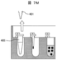
- the integrated stem mechanism 111 descends (FIG. 7J) and reaches the bottom dead center (FIG. 7K). While the integrated stem mechanism 111 is stopped for 0.5 seconds at the bottom dead center, the reaction vessel 110 is slightly moved (eccentric) toward the notch 509 in the y-axis direction (indicated by the arrow in FIG. 7L). Direction), the flange portion 406 of the cover 405 is sandwiched between the cover holding portions (the gap between the upper pressing plate 507 and the lower pressing plate 508). When waiting here, the integrated stem mechanism 111 rises, so that the cover 405 is pressed by the pressing plates 507 and 508, and the cover 405 is removed from the stem 401 (FIG. 7M).
- the reaction vessel 110 is slightly moved in the y-axis direction (that is, eccentric to the opposite side to the notch 509), and the magnetic chip 402 is moved to the gap between the upper pressing plate 507 and the lower pressing plate 508. If the integrated stem mechanism 111 is raised in FIG. 7Q, the stem 401 with the magnetic chip attached is positioned above the reaction vessel 110.
- a cover 405 is attached to the stem 401 from above the magnetic chip 402. That is, in FIG. 7R, the reaction vessel 110 is moved so that the cover storage well 501 comes directly under the stem 401 with the magnetic chip 402 attached. In FIG. 7S, the integrated stem mechanism 111 is lowered to allow the stem 401 with the magnetic tip 402 to enter the cover storage well 501. As a result, the cover 405 is attached to the stem 401. In FIG. 7T, the reaction vessel 110 is slightly moved in the direction of the arrow (movement in a direction in which the cover 401 and the stem 401 with the magnetic tip are eccentric relative to the notch 509 relative to the cover storage well 501). As a result, the cover 401 and the stem 401 with the magnetic tip are detached from the holding plates 507 and 508. In this state, as shown in FIG. 7U, the cover 401 and the stem 401 with the magnetic tip are pulled up.
- the reaction vessel 110 is moved so that the reaction well 503 comes directly under the stem 401 with the magnetic chip 402 and the cover 405 attached, and the reaction vessel 110 is stopped at this position.
- the integrated stem mechanism 111 is lowered in FIG. 7W and the magnetic chip 402 and the cover 405 enter the reaction well 503, the magnetic beads 702 are collected.
- the stem mechanism when collecting the magnetic beads, the stem mechanism temporarily stops at the bottom dead center, and thereafter, the integrated stem mechanism 111 is raised as shown in FIG. 7Y. If the magnetic beads are not sufficiently collected by one reciprocating (up and down) movement of the stem, the integral stem mechanism may be set to reciprocate (up and down) a plurality of times.
- the integrated stem mechanism 111 is positioned above the reaction vessel 110 by the integrated stem mechanism drive control unit 112 (the state where the magnetic beads 702 are collected: the state shown in FIG. 7Y). Then, the reaction vessel 110 is moved so that the washing well (# 1) 504 is located directly under the magnetic chip 402 and the cover 405 (that is, directly under the integrated stem mechanism). Thereafter, the stem mechanism 111 is lowered, and the cover 405 with magnetic beads and the magnetic chip 402 are caused to enter the cleaning well (# 1) 504.
- the reaction vessel 110 is slightly moved so that the flange portion 406 of the cover 405 is sandwiched (locked) by the holding plates 507 and 508 above the cleaning well (# 1) 504. Move (that is, the cover 405 is eccentric to the notch 509 side of the pressing plate). In this state, with the cover 405 remaining and the magnetic chip 402 mounted on the stem 401, the stem mechanism 111 is raised and the reaction vessel 110 is moved so that the magnetic chip storage well 502 comes directly under the stem mechanism 111. . By this operation, the magnetic beads 702 are immersed in the cleaning solution of the cleaning well (# 1) 504 away from the cover 405.
- the stem mechanism 111 and the reaction vessel are operated so as to perform the reverse operation of FIGS. 7N to 7Q (that is, the operation of FIGS. 7Q to 7N). 110 is operated. Thereafter, the reaction vessel 110 is moved again so that the washing well (# 1) 504 comes directly under the stem mechanism 111. Thereafter, the stem mechanism 111 is lowered, the cover 405 locked to the pressing plates 507 and 508 of the cleaning well (# 1) 504 is mounted again on the stem 401, and the locking of the cover 405 to the pressing plate is released. The reaction vessel 110 is slightly moved to move the stem mechanism 111 up and down. By this vertical movement, stirring is performed in the cleaning liquid, and cleaning with the magnetic beads 702 is performed in the cleaning well (# 1) 504. By this washing, impurities such as proteins derived from biological samples can be removed from the surface of the magnetic beads.
- the cover 405 is left on the cleaning well (# 1) 504 with the pressing plates 507 and 508 without performing the reverse operation of FIGS. 7N to 7Q, and the integral stem mechanism 111 is simply raised.
- the magnetic chip 402 is separated from the cover 405 together with the stem 401, the magnetic beads 702 are detached from the cover 405 and immersed in the cleaning liquid in the cleaning well.
- the above-described stirring action due to the vertical movement of the cover cannot be expected, and the cleaning time is longer than that with stirring of the cleaning liquid.
- the reaction vessel 110 and the stem mechanism 111 are moved and controlled so that the magnetic chip 402 and the cover 405 are mounted on the stem 401 again, and the magnetic chip 402 and the cover 405 are washed with the washing well (# 1).
- the magnetic beads 702 are collected again on the cover 405.
- the stem mechanism 111 is raised with the magnetic beads 702 collected in this manner, and the reaction vessel 110 is moved so that the washing well (# 2) 505 is located directly below the stem mechanism 111.
- the second cleaning operation is performed by operating the reaction vessel 110 and the stem mechanism 111 in the same manner as the first cleaning.
- the stem 401 on which the magnetic chip 402 and the cover 405 that has adsorbed the magnetic beads 702 after washing are mounted relative to the elution well 506 by the vertical movement control of the stem mechanism 111 and the movement control of the reaction vessel 110 in the well arrangement direction. Move. Thereafter, operations similar to the cover attaching / detaching operation and the magnetic chip attaching / detaching operation performed in the cleaning process (stem vertical movement and reaction container arrangement direction moving control) are also performed between the elution well 506 and the magnetic chip storage well 502. Thereby, the magnetic beads 702 are detached from the cover 405 and immersed in the eluent in the elution well 506.
- each process so far includes the periodic vertical movement control of the integrated stem mechanism 111 by the stem mechanism drive control unit 112 and the well arrangement direction (y of the reaction vessel 110 by the reaction container drive control unit 132). (Axis direction) can only be achieved by translational motion control.
- the nucleic acid component adsorbed on the surface of the magnetic bead 702 can be eluted in the eluent.
- a series of processes of nucleic acid extraction, separation, and purification is performed.
- the magnetic beads 702 in the eluent are collected again at the tip of the cover 405 using the magnetic chip 402.
- the integrated stem mechanism 111 has an x-axis direction.
- a movement mechanism (not shown) in the y-axis direction is added, and the integrated stem mechanism 111 is moved above the waste container 117 under the control of the stem mechanism drive control unit 112, and the nozzle mechanism 105 or the waste container 117 is moved.
- the cover 405 and the magnetic chip 402 are set to be discarded in a state in which the magnetic bead 702 is captured at the tip by operating the detaching mechanism attached to the head.
- only the cover 405 may be removed and discarded, and the magnetic chip 402 not in contact with the liquid may be recovered and reused.
- the z-axis direction moving mechanism (stem up-and-down moving mechanism) is provided to the integrated stem mechanism 111, and the magnetic chip 402 and the cover 405 are discarded by the user himself / herself when replacing the reaction container 110. You may make it discard in a container. In this way, since the integral stem mechanism only needs to move in the z-axis direction, the mechanism and control can be simplified.
- the magnetic beads 702 are collected (captured) at the tip of the cover 405 and moved from the reaction well 503 to the elution well 506.
- dispensing inside the apparatus is executed by one syringe pump, and a series of processes (stirring, collecting magnetic beads, etc.) relating to extraction of biological molecules performed in the reaction vessel are integrated.
- This is realized by the movement of the stem mechanism in the z-axis direction and the uniaxial movement of each reaction vessel in the y-axis direction.
- the number of axes is one axis regardless of the number of parallel processes, and in order to increase the degree of parallelism, it is only necessary to add one y-axis per reaction vessel. Can be suppressed.
- a reaction container (sample) is randomly processed as needed.
- a series of independent treatments for each reaction vessel for example, disrupting cells and extracting biological molecules into the solution, separating the extracted biological molecules from the solution with magnetic beads
- the treatment of washing the magnetic beads and eluting (purifying) the biological molecules adsorbed thereto with an eluent can be performed.
- the arrangement direction of wells in which various treatments are performed coincides with the movement direction of the reaction container, and the magnetic chip provided in the reaction container and the notch of the attaching / detaching mechanism (pressing plate) for the cover are provided. Since the portion is provided in alignment with the well arrangement direction, and the opening of these notches is also directed to the well arrangement direction, a reaction container that enables the above-described sample processing method to be performed is provided. be able to.
- Reaction container drive control part 133 ... Computer, 201 ... Stage, 202 ... Movable element, 203 ... Screw rod, 401 ... Stem, 402 ... Magnetic chip 403... Magnetic body 404.
Abstract
Description
(試料処理装置1)
すなわち、生物学的試料を試薬と反応させて一連の処理が行なわれる反応容器を備え、前記反応容器には、前記一連の処理が行われるよう配列された複数の処理部が設けられている試料処理装置において、
前記反応容器を複数並置できる反応容器セット部と、
前記反応容器セット部にセットされた前記反応容器を、反応容器ごとに独立して前記処理部の配列方向に移動させる反応容器移動機構と、
前記反応容器と協働して前記一連の処理に使用される複数のステムがそれぞれの反応容器に対応して前記反応容器セット部の上方に上下移動可能に配置され、これらのステムは、前記反応容器の移動方向と交差する方向に列をなし、前記反応容器セット部に並置される反応容器同士の処理部間のピッチに合わせたピッチで配列されているステム機構と、
前記ステム機構を上下移動させるステム上下移動機構と、
前記一連の処理のために前記反応容器移動機構と前記ステム上下移動機構とを連動させて、各反応容器の該当の処理部が処理手順にしたがって前記ステム機構の直下にきた時に対応のステム或いはそれに装着されるツール(例えば磁性チップおよびそのカバー)が処理部内に出入りする制御を行う制御部と、
を備えることを特徴とする。
(付属的態様)
(1)前記反応容器は、試薬及び磁性ビーズを用いて前記生物学的試料から生物学的分子を少なくとも抽出するためのものであり、前記処理部として、
前記生物学的試料、生物学的分子抽出用の試薬、生物学的分子吸着用の磁性ビーズが供給される反応部と、
生物学的分子を吸着した前記磁性ビーズを回収するために用いる磁性チップを、前記ステムに着脱するために格納する磁性チップ格納部と、
前記磁性チップのカバーを、前記ステムに着脱するために格納するカバー格納部と、
前記生物学的分子を吸着した前記磁性ビーズを洗浄するための洗浄液を収容する洗浄部と、
洗浄された前記磁性ビーズを受け入れて前記磁性ビーズ表面から前記生物学的分子を溶出させる溶出部と、
を備える。
(2)前記ステム機構は、複数の前記ステムが一体式に上下移動可能に支持される一体式ステム機構であり、
前記ステム上下移動機構は、前記制御部からの制御信号により、一つの駆動源によって前記一体式ステム機構を周期的に上下運動させる機構を有し、
前記反応容器移動機構は、前記ステム上下移動機構の周期的な上下方向の運動に合わせて、複数の前記処理部が処理順に従って前記ステム上下移動機構の直下にくるように前記制御部により移動制御される。
(3)前記反応容器移動機構は、前記反応容器セット部にセットされる前記反応容器を直線方向に移動させる機構、或いは、前記反応容器セット部にセットされる前記反応容器を、1軸を中心に回転方向に移動させる機構である。
(4)前記磁性チップおよび前記カバーは、先端と反対側の基端が開口して、その開口部の内径を前記磁性チップよりも前記カバーの方を大きくしてあり、且つ各開口周縁にフランジ部を有し、
前記ステムには、前記各開口を通して前記磁性チップ及びカバーを着脱するための異なる外径部がステム先端側からステム中間部にかけて設けられ、
前記反応用容器には、前記磁性チップ或いは前記カバーが前記処理部に挿入された時に、前記磁性チップ或いは前記カバーを前記処理部に対して反応容器を介して偏心移動させることで該反応容器に係合,離脱させる着脱機構を備える。
(5)前記着脱機構は、前記処理部の開口上方に対向して設けられた上部押さえ板と下部押さえ板とよりなり、これらの押さえ板には、前記磁性チップ及び前記カバーの外径に適合して前記偏心移動を受け入れる曲率の異なる切欠き部が設けられており、
これらの切欠き部が前記反応容器の移動方向に配列され、かつ前記各切欠き部の開口も前記反応容器の移動方向に向けられている。
(試料処理装置2)
さらに、上記試料処理装置1の構成要件に加えて、前記反応容器は、試薬及び磁性ビーズを用いて生物学的試料から生物学的分子の少なくとも抽出に関する一連の処理が行なわれる反応容器を備え、前記処理部として、少なくとも、
生物学的試料、生物学的分子抽出用の試薬、生物学的分子吸着用の磁性ビーズが供給される反応部と、
生物学的分子を吸着した前記磁性ビーズを回収するために用いる磁性チップを、前記ステムに着脱するために格納する磁性チップ格納部と、
前記磁性チップのカバーを、前記ステムに着脱するために格納するカバー格納部と、を備える試料処理装置2を提案する。
(試料処理方法)
また、試料装置2を用いて、次のような試料処理方法を提案する。
前記一連の処理に上記試料処理装置(2)が用いられ、
前記反応容器セット部に前記反応容器を随時必要に応じてセットし、前記一連の処理にしたがって該当の処理部が前記一体式ステムの直下にくるように、各反応容器を前記反応容器移動機構により独立して移動制御する工程と、
前記処理部が前記一体式ステム機構の直下にきた時に、対応のステムに装着した前記磁性チップ或いは前記カバーが前記処理部内に出入りする制御を行う工程と、
を含むことを特徴とする。
(付随的態様)
また、上記の本発明の試料方法において、以下のような任意に態様を含む。
(1)前記ステム機構は、前記反応容器の移動制御に連動して周期的に上下移動し、上死点、下死点にある時に所定の停止期間を設けるように設定されている。
(2)前記反応容器には、前記磁性チップ或いは前記カバーが前記処理部に挿入された時に、前記磁性チップ或いは前記カバーを前記処理部に対して反応容器を介して偏心移動させることで係合,離脱させる着脱機構を備え、
前記着脱機構は、前記処理部の開口上方に対向して設けられた上部押さえ板と下部押さえ板とよりなり、これらの押さえ板には、前記磁性チップ及び前記カバーの外径に適合して前記偏心移動を受け入れる切欠き部が設けられており、
これらの切欠き部が前記反応容器の移動方向に配列され、かつ前記各切欠き部の開口も前記反応容器の移動方向に向けられており、
前記反応容器を前記反応容器移動機構により独立して移動制御する工程は、前記処理部の間の移動に加えて、前記磁性チップ或いは前記カバーを対応の前記処理部に着脱させるために前記偏心移動させる制御も含む。
(反応容器)
さらに、上記した試料処理装置及び方法に用いる反応容器として、次のようなものを提案する。
前記ウェルとして、少なくとも、
生物学的試料、生物学的分子抽出用の試薬、生物学的分子吸着用の磁性ビーズが供給される反応ウェルと、
生物学的分子を吸着した前記磁性ビーズを回収するために用いる磁性チップを、前記ステムに着脱するために格納する磁性チップ格納ウェルと、
前記磁性チップのカバーを、前記ステムに着脱するために格納するカバー格納ウェルと、を備え、
さらに前記箱形本体には、前記磁性チップ或いは前記カバーがこれらのウェルのいずれか一つに選択的に挿入された時に、前記磁性チップ或いは前記カバーをウェルに対して反応容器を介して偏心移動させることで係合,離脱させる着脱機構を備え、
前記着脱機構は、前記処理部の開口上方に対向して設けられた上部押さえ板と下部押さえ板とよりなり、これらの押さえ板には、前記磁性チップ及び前記カバーの外径に適合して前記偏心移動を受け入れる切欠き部が設けられており、
これらの切欠き部が前記ウェルの配列方向に一致して設けられ、かつこれらの切欠き部の開口も前記ウェルの配列方向に向けられていることを特徴とする。
(付随的態様)
また、本発明に係る反応容器において、以下のような態様を任意に含む。
(1)前記上部押さえ板と前記下部押さえ板は、前記磁性チップ及び前記カバーに共用であり、各押さえ板に、前記磁性チップの外径に対応する曲率と前記カバーの外径に対応する曲率とを有する切欠き要素が複合的に形成されている。
(2)前記上部押さえ板と前記下部押さえ板は、前記磁性チップ用と前記カバー用とに分けて別々に配置され、前記磁性チップ用の上部押さえ板および下部押さえ板に、前記磁性チップの外径に対応する曲率の切欠き部が形成され、前記カバー用の上部押さえ板および下部押さえ板に、前記カバーの外径に対応する曲率の切欠き部が形成されている。
(試料処理装置の構成)
図1に、本発明に係る試料処理装置の構成例を模式的に示す。試料処理装置は、載置台101と、処理対象の生物学的試料を充填した試料容器を収容できる検体ラック102と、複数の試薬瓶を収容できる試薬ラック103と、複数のディスポーザブルチップを収容したチップラック104と、廃棄物を捨てるための廃棄物用容器117と、載置台101の一面に対向する位置にx軸、y軸、z軸方向に移動可能に配置されるノズル機構105と、ノズル機構105の移動、吸引および吐出を制御する駆動制御部109と、生物学的試料から生物学的分子を抽出、分離、精製する一連の処理が行なわれる反応容器110と、この反応容器110と協働して前記一連の処理を行うために用いる一体式ステム機構111と、反応容器110を複数並置できる反応容器セット部120と、反応容器セット部120にセットされた反応容器110を、反応容器ごとに独立して並進運動(直進移動)させる反応容器移動機構(図2Aの反応容器搭載ステージ201、可動子202、スクリューロッド203、サーボモータ(アクチュエータ)116)とを備えている。
(反応容器の移動)
図2Aに、図1における反応容器セット部120をx軸方向から見た断面模式図を、図2Bに、図1における反応容器をy軸方向から見た断面模式図を示す。
(ステム)
ステム401には、磁性チップ402およびカバー405の各開口を通して磁性チップ及びカバーを着脱するための異なる外径部がステム先端側からステム中間部にかけて設けられている。
(反応容器)
図5Aに、本発明に係る試料処理装置における反応容器の構成例を斜視図により示す。
また、図5Bに、図5Aの平面図を示す。
また、この段階では、反応ウェル503の内部を撹拌しても良い。反応ウェル503の内部を撹拌するには、例えば、反応容器110の外部から磁界を周期的に印加することで磁性ビーズ702を内部で移動させる方法、又は、ステム401にカバー405を取り付け、一体式シャフト機構駆動制御部112で一体式ステム機構111を制御してステム401に取り付けたカバー405を反応ウェル503内部で揺動させる方法を使用することができる(図7H)。
その後、ステム機構111を下降させて、洗浄ウェル(#1)504に磁性ビーズ付きカバー405及び磁性チップ402を進入させる。ステム機構111が下死点に達した後に、カバー405のフランジ部406が洗浄ウェル(#1)504上方の押さえ板507,508に挟まれる(係止する)ように、反応容器110をわずかに移動させる(すなわち、カバー405を押さえ板の切欠き部509側に偏心させる)。この状態で、カバー405を残して、ステム401に磁性チップ402を装着した状態で、ステム機構111を上昇させ、ステム機構111の真下に磁性チップ格納ウェル502が来るように反応容器110を移動させる。この動作により磁性ビーズ702は、カバー405から離れて洗浄ウェル(#1)504の洗浄液内に浸漬される。ステム401に装着した磁性チップ402を磁性チップ格納ウェル502に戻すために、既述した図7N~図7Qの逆動作(すなわち図7Q~図7Nの動作)を行なうようにステム機構111および反応容器110を動作させる。その後に、ステム機構111の真下に再度、洗浄ウェル(#1)504が来るように反応容器110を移動させる。その後、ステム機構111を下降させて、洗浄ウェル(#1)504の押さえ板507,508に係止されているカバー405をステム401に再度装着し、カバー405の押さえ板に対する係止が解除されるよう反応容器110をわずかに移動させてステム機構111を上下運動させる。この上下運動により洗浄液内で攪拌が行なわれ洗浄ウェル(#1)504内で磁性ビーズ702での洗浄が行なわれる。
この洗浄により、生物学的試料に由来するタンパク質等の不純物を磁性ビーズ表面から除去することができる。
Claims (15)
- 生物学的試料を試薬と反応させて一連の処理が行なわれる反応容器を備え、前記反応容器には、前記一連の処理が行われるよう配列された複数の処理部が設けられている試料処理装置において、
前記反応容器を複数並置できる反応容器セット部と、
前記反応容器セット部にセットされた前記反応容器を、反応容器ごとに独立して前記処理部の配列方向に移動させる反応容器移動機構と、
前記反応容器と協働して前記一連の処理に使用される複数のステムがそれぞれの反応容器に対応して前記反応容器セット部の上方に上下移動可能に配置され、これらのステムは、前記反応容器の移動方向と交差する方向に列をなし、前記反応容器セット部に並置される反応容器同士の処理部間のピッチに合わせたピッチで配列されているステム機構と、
前記ステム機構を上下移動させるステム上下移動機構と、
前記一連の処理のために前記反応容器移動機構と前記ステム上下移動機構とを連動させて、各反応容器の該当の処理部が処理手順にしたがって前記ステム機構の直下にきた時に対応のステム或いはそれに装着されるツールが処理部内に出入りする制御を行う制御部と、
を備えることを特徴とする試料処理装置。 - 請求項1記載の試料処理装置において、
前記反応容器は、試薬及び磁性ビーズを用いて前記生物学的試料から生物学的分子を少なくとも抽出するためのものであり、前記処理部として、
前記生物学的試料、生物学的分子抽出用の試薬、生物学的分子吸着用の磁性ビーズが供給される反応部と、
生物学的分子を吸着した前記磁性ビーズを回収するために用いる磁性チップを、前記ステムに着脱するために格納する磁性チップ格納部と、
前記磁性チップのカバーを、前記ステムに着脱するために格納するカバー格納部と、
前記生物学的分子を吸着した前記磁性ビーズを洗浄するための洗浄液を収容する洗浄部と、
洗浄された前記磁性ビーズを受け入れて前記磁性ビーズ表面から前記生物学的分子を溶出させる溶出部と、
を備える試料処理装置。 - 請求項1記載の試料処理装置において、
前記ステム機構は、複数の前記ステムが一体式に上下移動可能に支持される一体式ステム機構であり、
前記ステム上下移動機構は、前記制御部からの制御信号により、一つの駆動源によって前記一体式ステム機構を周期的に上下運動させる機構を有し、
前記反応容器移動機構は、前記ステム上下移動機構の周期的な上下方向の運動に合わせて、複数の前記処理部が処理順に従って前記ステム上下移動機構の直下にくるように前記制御部により移動制御される試料処理装置。 - 請求項1記載の試料処理装置において、
前記反応容器移動機構は、前記反応容器セット部にセットされる前記反応容器を直線方向に移動させる試料処理装置。 - 請求項1記載の試料処理装置において、
前記反応容器移動機構は、前記反応容器セット部にセットされる前記反応容器を、1軸を中心に回転方向に移動させる試料処理装置。 - 請求項2記載の試料処理装置において、
前記磁性チップおよび前記カバーは、先端と反対側の基端が開口して、その開口部の内径を前記磁性チップよりも前記カバーの方を大きくしてあり、且つ各開口周縁にフランジ部を有し、
前記ステムには、前記各開口を通して前記磁性チップ及びカバーを着脱するための異なる外径部がステム先端側からステム中間部にかけて設けられ、
前記反応用容器には、前記磁性チップ或いは前記カバーが前記処理部に挿入された時に、前記磁性チップ或いは前記カバーを前記処理部に対して反応容器を介して偏心移動させることで該反応容器に係合,離脱させる着脱機構を備える試料処理装置。 - 請求項6記載の試料処理装置において、
前記着脱機構は、前記処理部の開口上方に対向して設けられた上部押さえ板と下部押さえ板とよりなり、これらの押さえ板には、前記磁性チップ及び前記カバーの外径に適合して前記偏心移動を受け入れる曲率の異なる切欠き部が設けられており、
これらの切欠き部が前記反応容器の移動方向に配列され、かつ前記各切欠き部の開口も前記反応容器の移動方向に向けられている試料処理装置。 - 試薬及び磁性ビーズを用いて生物学的試料から生物学的分子の少なくとも抽出に関する一連の処理が行なわれる反応容器を備え、前記反応容器には、前記一連の処理が行われるよう配列された複数の処理部が設けられている試料処理装置において、
前記反応容器は、試薬及び磁性ビーズを用いて前記生物学的試料から前記生物学的分子を抽出するために、前記処理部として、少なくとも、
生物学的試料、生物学的分子抽出用の試薬、生物学的分子吸着用の磁性ビーズが供給される反応部と、
生物学的分子を吸着した前記磁性ビーズを回収するために用いる磁性チップを、前記ステムに着脱するために格納する磁性チップ格納部と、
前記磁性チップのカバーを、前記ステムに着脱するために格納するカバー格納部と、を備え、
且つ前記試料処理装置は、
前記反応容器を複数並置できる反応容器セット部と、
前記反応容器セット部にセットされた前記反応容器を、反応容器ごとに独立して前記処理部の配列方向に移動させる反応容器移動機構と、
前記反応容器と協働して前記一連の処理に使用される複数のステムがそれぞれの反応容器に対応して前記反応容器セット部の上方に上下移動可能に配置され、これらのステムは、前記反応容器の移動方向と交差する方向に列をなし、前記反応容器セット部に並置される反応容器同士の処理部間のピッチに合わせたピッチで配列されているステム機構と、
前記ステム機構を上下移動させるステム上下移動機構と、
前記一連の処理のために前記反応容器ごとの処理部配列方向の移動と前記ステム機構の上下移動とを連動制御して、前記処理部の一つが処理手順にしたがって前記ステム機構の直下にきた時に対応のステム或いはそれに装着される前記磁性チップ及びカバーが処理部内に出入りする制御を行う制御部と、
を備えることを特徴とする試料処理装置。 - 請求項8記載の試料処理装置において、
前記処理部としてさらに、前記生物学的分子を吸着した前記磁性ビーズを洗浄するための洗浄液を収容する洗浄部と、洗浄された前記磁性ビーズを受け入れて前記磁性ビーズ表面から前記生物学的分子を溶出させる溶出部と、を備える試料処理装置。 - 生物学的試料から生物学的分子を抽出,分離,精製する一連の処理を行なう試料処理方法において、
前記一連の処理に請求項8又は請求項9記載の試料処理装置が用いられ、
前記反応容器セット部に前記反応容器を随時必要に応じてセットし、前記一連の処理にしたがって該当の処理部が前記一体式ステムの直下にくるように、各反応容器を前記反応容器移動機構により独立して移動制御する工程と、
前記処理部が前記一体式ステム機構の直下にきた時に、対応のステムに装着した前記磁性チップ或いは前記カバーが前記処理部内に出入りする制御を行う工程と、
を含むことを特徴とする試料処理方法。 - 請求項10記載の試料処理方法において、
前記ステム機構は、前記反応容器の移動制御に連動して周期的に上下移動し、上死点、下死点にある時に所定の停止期間を設けるように設定されている試料処理方法。 - 請求項10記載の試料処理方法において、
前記反応容器には、前記磁性チップ或いは前記カバーが前記処理部に挿入された時に、前記磁性チップ或いは前記カバーを前記処理部に対して反応容器を介して偏心移動させることで係合,離脱させる着脱機構を備え、
前記着脱機構は、前記処理部の開口上方に対向して設けられた上部押さえ板と下部押さえ板とよりなり、これらの押さえ板には、前記磁性チップ及び前記カバーの外径に適合して前記偏心移動を受け入れる切欠き部が設けられており、
これらの切欠き部が前記反応容器の移動方向に配列され、かつ前記各切欠き部の開口も前記反応容器の移動方向に向けられており、
前記反応容器を前記反応容器移動機構により独立して移動制御する工程は、前記処理部間の移動に加えて、前記磁性チップ或いは前記カバーを対応の前記処理部に着脱させるために前記偏心移動させる制御も含む試料処理方法。 - 試薬及び磁性ビーズを用いて生物学的試料から生物学的分子を抽出するために使用される反応容器であって、箱形を呈し、箱形本体に前記一連の処理が行われるよう配列された複数のウェルが設けられている反応容器において、
前記ウェルとして、少なくとも、
生物学的試料、生物学的分子抽出用の試薬、生物学的分子吸着用の磁性ビーズが供給される反応ウェルと、
生物学的分子を吸着した前記磁性ビーズを回収するために用いる磁性チップを、前記ステムに着脱するために格納する磁性チップ格納ウェルと、
前記磁性チップのカバーを、前記ステムに着脱するために格納するカバー格納ウェルと、を備え、
さらに前記箱形本体には、前記磁性チップ或いは前記カバーがこれらのウェルのいずれか一つに選択的に挿入された時に、前記磁性チップ或いは前記カバーをウェルに対して反応容器を介して偏心移動させることで係合,離脱させる着脱機構を備え、
前記着脱機構は、前記処理部の開口上方に対向して設けられた上部押さえ板と下部押さえ板とよりなり、これらの押さえ板には、前記磁性チップ及び前記カバーの外径に適合して前記偏心移動を受け入れる切欠き部が設けられており、
これらの切欠き部が前記ウェルの配列方向に一致して設けられ、かつこれらの切欠き部の開口も前記ウェルの配列方向に向けられていることを特徴とする反応容器。 - 請求項13記載の反応容器において、
前記上部押さえ板と前記下部押さえ板は、前記磁性チップ及び前記カバーに共用であり、各押さえ板に、前記磁性チップの外径に対応する曲率と前記カバーの外径に対応する曲率とを有する切欠き要素が複合的に形成されている反応容器。 - 請求項13記載の反応容器において、
前記上部押さえ板と前記下部押さえ板は、前記磁性チップ用と前記カバー用とに分けて別々に配置され、前記磁性チップ用の上部押さえ板および下部押さえ板に、前記磁性チップの外径に対応する曲率の切欠き部が形成され、前記カバー用の上部押さえ板および下部押さえ板に、前記カバーの外径に対応する曲率の切欠き部が形成されている反応容器。
Priority Applications (3)
| Application Number | Priority Date | Filing Date | Title |
|---|---|---|---|
| DE112012002014.6T DE112012002014B4 (de) | 2011-05-30 | 2012-05-21 | Probenverarbeitungsvorrichtung, Probenverarbeitungsverfahren und in dieser Vorrichtung bzw. diesem Verfahren verwendeter Reaktionsbehälter |
| CN201280026705.XA CN103562727B (zh) | 2011-05-30 | 2012-05-21 | 试样处理装置、试样处理方法以及所使用的反应容器 |
| US14/122,325 US8906304B2 (en) | 2011-05-30 | 2012-05-21 | Sample processing device, sample treatment method, and reaction container used in these device and method |
Applications Claiming Priority (2)
| Application Number | Priority Date | Filing Date | Title |
|---|---|---|---|
| JP2011-119955 | 2011-05-30 | ||
| JP2011119955A JP5650056B2 (ja) | 2011-05-30 | 2011-05-30 | 試料処理装置、および試料処理方法 |
Publications (1)
| Publication Number | Publication Date |
|---|---|
| WO2012165187A1 true WO2012165187A1 (ja) | 2012-12-06 |
Family
ID=47259048
Family Applications (1)
| Application Number | Title | Priority Date | Filing Date |
|---|---|---|---|
| PCT/JP2012/062891 WO2012165187A1 (ja) | 2011-05-30 | 2012-05-21 | 試料処理装置、試料処理方法、およびこれらに使用する反応容器 |
Country Status (5)
| Country | Link |
|---|---|
| US (1) | US8906304B2 (ja) |
| JP (1) | JP5650056B2 (ja) |
| CN (1) | CN103562727B (ja) |
| DE (1) | DE112012002014B4 (ja) |
| WO (1) | WO2012165187A1 (ja) |
Cited By (1)
| Publication number | Priority date | Publication date | Assignee | Title |
|---|---|---|---|---|
| CN110290875A (zh) * | 2017-02-03 | 2019-09-27 | 美可生物医学有限公司 | 一种用于从生物学试料分离或纯化目标物质的装置和方法 |
Families Citing this family (28)
| Publication number | Priority date | Publication date | Assignee | Title |
|---|---|---|---|---|
| JP5650056B2 (ja) | 2011-05-30 | 2015-01-07 | 株式会社日立ハイテクノロジーズ | 試料処理装置、および試料処理方法 |
| CA2842359A1 (en) | 2011-08-01 | 2013-02-07 | Denovo Sciences | Cell capture system and method of use |
| US11008628B1 (en) * | 2013-02-18 | 2021-05-18 | Labrador Diagnostics Llc | Systems and methods for analyte testing and laboratory oversight |
| US10401373B1 (en) | 2013-02-18 | 2019-09-03 | Theranos Ip Company, Llc | Systems and methods for analyte testing and laboratory oversight |
| US10391490B2 (en) | 2013-05-31 | 2019-08-27 | Celsee Diagnostics, Inc. | System and method for isolating and analyzing cells |
| US11360107B1 (en) | 2014-02-25 | 2022-06-14 | Labrador Diagnostics Llc | Systems and methods for sample handling |
| CN104436753B (zh) * | 2014-12-09 | 2016-05-25 | 天津博纳艾杰尔科技有限公司 | 一种固相萃取仪 |
| ES2596708B1 (es) | 2015-07-08 | 2017-04-12 | Kiro Grifols S.L | Máquina y procedimiento para la preparación automática de sustancias de aplicación intravenosa |
| CN114432943A (zh) | 2015-07-24 | 2022-05-06 | 新型微装置有限责任公司(Dba 新型装置) | 标本提取装置及其使用方法 |
| CN105137056B (zh) * | 2015-08-28 | 2017-07-18 | 深圳市锦瑞生物科技有限公司 | 一种生化分析仪 |
| CN106554901B (zh) * | 2015-09-30 | 2019-06-14 | 精专生医股份有限公司 | 自动化萃取核酸的机台及配合其使用的针筒 |
| JP6771903B2 (ja) | 2016-02-29 | 2020-10-21 | シスメックス株式会社 | 検体前処理装置、検体前処理カートリッジおよび検体前処理方法 |
| JP6918914B2 (ja) * | 2016-02-29 | 2021-08-11 | シスメックス株式会社 | 検体前処理カートリッジを用いた前処理方法 |
| US11204358B2 (en) | 2016-05-25 | 2021-12-21 | Universal Bio Research Co., Ltd. | Specimen processing and measuring system |
| CN106381259B (zh) * | 2016-09-27 | 2018-09-11 | 深圳市港科深研生物科技有限公司 | 外周血单个核细胞的体外提取装置和外周血单个核细胞的体外提取方法 |
| CN109564212A (zh) * | 2016-10-13 | 2019-04-02 | 松下知识产权经营株式会社 | 生物分子的提取方法、提取系统以及提取容器 |
| CN106918713B (zh) * | 2017-03-14 | 2019-04-12 | 复旦大学附属中山医院 | 一种全自动生物样品组分分选装置 |
| CN106771307A (zh) * | 2017-03-14 | 2017-05-31 | 骏实生物科技(上海)有限公司 | 磁性分析物收集转移系统及其方法 |
| CN110945363B (zh) * | 2017-07-21 | 2024-04-16 | Seegene株式会社 | 一种用于转移磁珠的模块,包括该模块的自动化系统以及使用该模块提取核酸的方法 |
| EP3651903A4 (en) | 2017-08-29 | 2021-06-16 | Bio-Rad Laboratories, Inc. | SYSTEM AND METHOD FOR ISOLATING AND ANALYZING CELLS |
| CN107760561B (zh) * | 2017-10-26 | 2019-05-28 | 深圳市汇研科创生物科技有限公司 | 核酸提取装置及核酸提取方法 |
| CN108051587B (zh) * | 2017-11-03 | 2020-02-14 | 无锡艾科瑞思产品设计与研究有限公司 | 一种具有搅拌功能的食物检测用酶标板 |
| CN110272808B (zh) * | 2018-03-13 | 2020-10-16 | 武汉医蒂生物科技有限公司 | 一种核酸提取系统 |
| CN108998368A (zh) * | 2018-08-01 | 2018-12-14 | 德诺杰亿(北京)生物科技有限公司 | 样本处理系统 |
| US10633693B1 (en) | 2019-04-16 | 2020-04-28 | Celsee Diagnostics, Inc. | System and method for leakage control in a particle capture system |
| CN114072490A (zh) | 2019-05-07 | 2022-02-18 | 伯乐实验室有限公司 | 用于自动化的单细胞加工的系统和方法 |
| US11273439B2 (en) | 2019-05-07 | 2022-03-15 | Bio-Rad Laboratories, Inc. | System and method for target material retrieval from microwells |
| CN112175943B (zh) * | 2020-10-29 | 2022-07-15 | 绍兴迅敏康生物科技有限公司 | 连续进样的测序建库仪及其操作方法 |
Citations (10)
| Publication number | Priority date | Publication date | Assignee | Title |
|---|---|---|---|---|
| JP2003504195A (ja) * | 1999-07-19 | 2003-02-04 | オルガノン・テクニカ・ベー・ヴエー | 磁性粒子を流体と混合するための装置および方法 |
| JP2004229657A (ja) * | 2003-01-29 | 2004-08-19 | Bionex Inc | 核酸又は様々な生物学的物質を分離及び精製するためのキットと、このキットを用いて生物学的物質の分離又は精製操作を自動化するためのシステム |
| JP2004337137A (ja) * | 2003-05-12 | 2004-12-02 | Marcom:Kk | 自動核酸抽出方法および自動核酸抽出装置 |
| WO2005118803A1 (ja) * | 2004-06-02 | 2005-12-15 | Arkray, Inc. | 核酸抽出用容器、固体マトリックスの洗浄方法および洗浄機構、ならびに核酸精製方法 |
| US20060144169A1 (en) * | 2005-01-05 | 2006-07-06 | Amir Porat | Combinatorial pipettor device |
| JP2006329986A (ja) * | 2005-05-24 | 2006-12-07 | Festo Corp | 試料をソースからターゲットに移送するための装置および方法 |
| JP2007279006A (ja) * | 2006-04-12 | 2007-10-25 | Bio-Magnetics Ltd | 組み合わせピペッター器具 |
| JP2008167722A (ja) * | 2007-01-15 | 2008-07-24 | Konica Minolta Medical & Graphic Inc | 磁性支持体上での加熱による核酸単離方法 |
| US20090176308A1 (en) * | 2007-11-13 | 2009-07-09 | Stratec Biomedical Systems Ag | Apparatus and method for the purification of biomolecules |
| JP2011501194A (ja) * | 2007-10-25 | 2011-01-06 | アボット・ラボラトリーズ | 超高感度免疫アッセイを実施する方法 |
Family Cites Families (13)
| Publication number | Priority date | Publication date | Assignee | Title |
|---|---|---|---|---|
| EP1130397B1 (en) * | 1993-02-01 | 2006-10-11 | Thermo Electron Oy | Equipment for determination of an analyte from a sample |
| IL123210A0 (en) * | 1998-02-06 | 1998-09-24 | Gombinsky Moshe | A device and system for the collection of magnetic particles |
| FI102906B1 (fi) * | 1998-02-23 | 1999-03-15 | Bio Nobile Oy | Menetelmä ja väline aineen siirtämiseksi |
| JP4474099B2 (ja) * | 2002-12-20 | 2010-06-02 | アークレイ株式会社 | 液体保存容器およびカートリッジ |
| JP2005037179A (ja) * | 2003-07-17 | 2005-02-10 | Mitsubishi Kagaku Iatron Inc | カートリッジシールの穿孔具を備えた自動測定装置 |
| US7534081B2 (en) | 2005-05-24 | 2009-05-19 | Festo Corporation | Apparatus and method for transferring samples from a source to a target |
| JP4328788B2 (ja) * | 2005-10-04 | 2009-09-09 | キヤノン株式会社 | 核酸試料検査装置 |
| CN201060199Y (zh) * | 2007-03-26 | 2008-05-14 | 台湾圆点奈米技术开发有限公司 | 全自动磁珠操作平台 |
| EP2397861B1 (en) | 2009-02-12 | 2019-03-06 | ARKRAY, Inc. | Analysis method, analysis apparatus, computer program used to implement said analysis method, and storage medium for this program |
| JP5292267B2 (ja) | 2009-12-16 | 2013-09-18 | 株式会社日立ハイテクノロジーズ | 試料処理装置、試料処理方法及びこれらに使用する反応容器 |
| JP5650056B2 (ja) | 2011-05-30 | 2015-01-07 | 株式会社日立ハイテクノロジーズ | 試料処理装置、および試料処理方法 |
| JP5745994B2 (ja) * | 2011-10-26 | 2015-07-08 | トヨタ自動車株式会社 | 組立装置 |
| JP5599488B2 (ja) | 2013-04-26 | 2014-10-01 | 株式会社日立ハイテクノロジーズ | 試料処理方法 |
-
2011
- 2011-05-30 JP JP2011119955A patent/JP5650056B2/ja active Active
-
2012
- 2012-05-21 DE DE112012002014.6T patent/DE112012002014B4/de active Active
- 2012-05-21 CN CN201280026705.XA patent/CN103562727B/zh active Active
- 2012-05-21 WO PCT/JP2012/062891 patent/WO2012165187A1/ja active Application Filing
- 2012-05-21 US US14/122,325 patent/US8906304B2/en active Active
Patent Citations (10)
| Publication number | Priority date | Publication date | Assignee | Title |
|---|---|---|---|---|
| JP2003504195A (ja) * | 1999-07-19 | 2003-02-04 | オルガノン・テクニカ・ベー・ヴエー | 磁性粒子を流体と混合するための装置および方法 |
| JP2004229657A (ja) * | 2003-01-29 | 2004-08-19 | Bionex Inc | 核酸又は様々な生物学的物質を分離及び精製するためのキットと、このキットを用いて生物学的物質の分離又は精製操作を自動化するためのシステム |
| JP2004337137A (ja) * | 2003-05-12 | 2004-12-02 | Marcom:Kk | 自動核酸抽出方法および自動核酸抽出装置 |
| WO2005118803A1 (ja) * | 2004-06-02 | 2005-12-15 | Arkray, Inc. | 核酸抽出用容器、固体マトリックスの洗浄方法および洗浄機構、ならびに核酸精製方法 |
| US20060144169A1 (en) * | 2005-01-05 | 2006-07-06 | Amir Porat | Combinatorial pipettor device |
| JP2006329986A (ja) * | 2005-05-24 | 2006-12-07 | Festo Corp | 試料をソースからターゲットに移送するための装置および方法 |
| JP2007279006A (ja) * | 2006-04-12 | 2007-10-25 | Bio-Magnetics Ltd | 組み合わせピペッター器具 |
| JP2008167722A (ja) * | 2007-01-15 | 2008-07-24 | Konica Minolta Medical & Graphic Inc | 磁性支持体上での加熱による核酸単離方法 |
| JP2011501194A (ja) * | 2007-10-25 | 2011-01-06 | アボット・ラボラトリーズ | 超高感度免疫アッセイを実施する方法 |
| US20090176308A1 (en) * | 2007-11-13 | 2009-07-09 | Stratec Biomedical Systems Ag | Apparatus and method for the purification of biomolecules |
Cited By (1)
| Publication number | Priority date | Publication date | Assignee | Title |
|---|---|---|---|---|
| CN110290875A (zh) * | 2017-02-03 | 2019-09-27 | 美可生物医学有限公司 | 一种用于从生物学试料分离或纯化目标物质的装置和方法 |
Also Published As
| Publication number | Publication date |
|---|---|
| CN103562727A (zh) | 2014-02-05 |
| US8906304B2 (en) | 2014-12-09 |
| DE112012002014B4 (de) | 2014-08-07 |
| JP2012247330A (ja) | 2012-12-13 |
| DE112012002014T5 (de) | 2014-03-06 |
| CN103562727B (zh) | 2015-11-25 |
| US20140087370A1 (en) | 2014-03-27 |
| JP5650056B2 (ja) | 2015-01-07 |
Similar Documents
| Publication | Publication Date | Title |
|---|---|---|
| JP5650056B2 (ja) | 試料処理装置、および試料処理方法 | |
| JP5292267B2 (ja) | 試料処理装置、試料処理方法及びこれらに使用する反応容器 | |
| JP3551293B2 (ja) | 核酸抽出装置 | |
| JP5998218B2 (ja) | 磁力体カバー及び核酸抽出装置 | |
| JP5202339B2 (ja) | 容器反復利用磁性粒子並行処理装置および容器反復利用磁性粒子並行処理方法 | |
| JP5890623B2 (ja) | 液体処理システム及び液体処理方法 | |
| US8685322B2 (en) | Apparatus and method for the purification of biomolecules | |
| WO2017027425A1 (en) | Modular liquid handling system | |
| JP3752417B2 (ja) | 核酸の精製方法および精製装置 | |
| WO2018181718A1 (ja) | 核酸分離装置 | |
| CN111989390A (zh) | 用于从样品提取生物分子的系统及相关方法 | |
| KR101282841B1 (ko) | 핵산 또는 생물학적 물질을 분리하기 위한 장치 및 방법 | |
| JP7141530B2 (ja) | 自動核酸抽出方法及び装置 | |
| WO2016031705A1 (ja) | 可変ピッチ分注装置を利用した磁性粒子反応制御装置およびその反応制御方法 | |
| JP2011234671A (ja) | 核酸抽出装置 | |
| KR20150012778A (ko) | 자성나노입자를 이용한 자동 분리 농축 처리장치 | |
| JP5771731B2 (ja) | 試料処理装置および試料処理方法に使用する反応容器 | |
| JP5599488B2 (ja) | 試料処理方法 | |
| CN108315243B (zh) | 自动化加样系统 | |
| JPWO2020162431A1 (ja) | 検体処理装置 | |
| CN113583798A (zh) | 用于磁棒法提取生物活性物质的磁针和套管系统和其应用 | |
| JP2000266764A (ja) | 分注用装置 | |
| JP2002243746A (ja) | 自動分離抽出装置 | |
| JP2018171029A (ja) | 核酸分離装置 |
Legal Events
| Date | Code | Title | Description |
|---|---|---|---|
| 121 | Ep: the epo has been informed by wipo that ep was designated in this application |
Ref document number: 12792863 Country of ref document: EP Kind code of ref document: A1 |
|
| WWE | Wipo information: entry into national phase |
Ref document number: 14122325 Country of ref document: US |
|
| WWE | Wipo information: entry into national phase |
Ref document number: 1120120020146 Country of ref document: DE Ref document number: 112012002014 Country of ref document: DE |
|
| 122 | Ep: pct application non-entry in european phase |
Ref document number: 12792863 Country of ref document: EP Kind code of ref document: A1 |