WO2012165174A1 - 抵抗加熱ヒータの劣化検出装置および方法 - Google Patents
抵抗加熱ヒータの劣化検出装置および方法 Download PDFInfo
- Publication number
- WO2012165174A1 WO2012165174A1 PCT/JP2012/062770 JP2012062770W WO2012165174A1 WO 2012165174 A1 WO2012165174 A1 WO 2012165174A1 JP 2012062770 W JP2012062770 W JP 2012062770W WO 2012165174 A1 WO2012165174 A1 WO 2012165174A1
- Authority
- WO
- WIPO (PCT)
- Prior art keywords
- temperature
- resistance
- heater
- value
- resistance heater
- Prior art date
- Legal status (The legal status is an assumption and is not a legal conclusion. Google has not performed a legal analysis and makes no representation as to the accuracy of the status listed.)
- Ceased
Links
Images




Classifications
-
- H—ELECTRICITY
- H10—SEMICONDUCTOR DEVICES; ELECTRIC SOLID-STATE DEVICES NOT OTHERWISE PROVIDED FOR
- H10P—GENERIC PROCESSES OR APPARATUS FOR THE MANUFACTURE OR TREATMENT OF DEVICES COVERED BY CLASS H10
- H10P72/00—Handling or holding of wafers, substrates or devices during manufacture or treatment thereof
- H10P72/06—Apparatus for monitoring, sorting, marking, testing or measuring
- H10P72/0602—Temperature monitoring
-
- C—CHEMISTRY; METALLURGY
- C23—COATING METALLIC MATERIAL; COATING MATERIAL WITH METALLIC MATERIAL; CHEMICAL SURFACE TREATMENT; DIFFUSION TREATMENT OF METALLIC MATERIAL; COATING BY VACUUM EVAPORATION, BY SPUTTERING, BY ION IMPLANTATION OR BY CHEMICAL VAPOUR DEPOSITION, IN GENERAL; INHIBITING CORROSION OF METALLIC MATERIAL OR INCRUSTATION IN GENERAL
- C23C—COATING METALLIC MATERIAL; COATING MATERIAL WITH METALLIC MATERIAL; SURFACE TREATMENT OF METALLIC MATERIAL BY DIFFUSION INTO THE SURFACE, BY CHEMICAL CONVERSION OR SUBSTITUTION; COATING BY VACUUM EVAPORATION, BY SPUTTERING, BY ION IMPLANTATION OR BY CHEMICAL VAPOUR DEPOSITION, IN GENERAL
- C23C16/00—Chemical coating by decomposition of gaseous compounds, without leaving reaction products of surface material in the coating, i.e. chemical vapour deposition [CVD] processes
- C23C16/44—Chemical coating by decomposition of gaseous compounds, without leaving reaction products of surface material in the coating, i.e. chemical vapour deposition [CVD] processes characterised by the method of coating
- C23C16/46—Chemical coating by decomposition of gaseous compounds, without leaving reaction products of surface material in the coating, i.e. chemical vapour deposition [CVD] processes characterised by the method of coating characterised by the method used for heating the substrate
-
- C—CHEMISTRY; METALLURGY
- C23—COATING METALLIC MATERIAL; COATING MATERIAL WITH METALLIC MATERIAL; CHEMICAL SURFACE TREATMENT; DIFFUSION TREATMENT OF METALLIC MATERIAL; COATING BY VACUUM EVAPORATION, BY SPUTTERING, BY ION IMPLANTATION OR BY CHEMICAL VAPOUR DEPOSITION, IN GENERAL; INHIBITING CORROSION OF METALLIC MATERIAL OR INCRUSTATION IN GENERAL
- C23C—COATING METALLIC MATERIAL; COATING MATERIAL WITH METALLIC MATERIAL; SURFACE TREATMENT OF METALLIC MATERIAL BY DIFFUSION INTO THE SURFACE, BY CHEMICAL CONVERSION OR SUBSTITUTION; COATING BY VACUUM EVAPORATION, BY SPUTTERING, BY ION IMPLANTATION OR BY CHEMICAL VAPOUR DEPOSITION, IN GENERAL
- C23C16/00—Chemical coating by decomposition of gaseous compounds, without leaving reaction products of surface material in the coating, i.e. chemical vapour deposition [CVD] processes
- C23C16/44—Chemical coating by decomposition of gaseous compounds, without leaving reaction products of surface material in the coating, i.e. chemical vapour deposition [CVD] processes characterised by the method of coating
- C23C16/52—Controlling or regulating the coating process
-
- H—ELECTRICITY
- H05—ELECTRIC TECHNIQUES NOT OTHERWISE PROVIDED FOR
- H05B—ELECTRIC HEATING; ELECTRIC LIGHT SOURCES NOT OTHERWISE PROVIDED FOR; CIRCUIT ARRANGEMENTS FOR ELECTRIC LIGHT SOURCES, IN GENERAL
- H05B1/00—Details of electric heating devices
- H05B1/02—Automatic switching arrangements specially adapted to apparatus ; Control of heating devices
- H05B1/0227—Applications
- H05B1/0288—Applications for non specified applications
Definitions
- the present invention relates to a resistance heater deterioration detection apparatus and method, and more particularly to a resistance heater deterioration detection apparatus and method used in a semiconductor manufacturing apparatus such as a crystal growth apparatus.
- Resistance heaters are suitable for uniform heating and are often used for substrate heating in crystal growth apparatuses such as MOCVD (Metal Organic Chemical Vapor Deposition) apparatuses.
- MOCVD Metal Organic Chemical Vapor Deposition
- a typical example of a material for a resistance heater for a crystal growth apparatus is molybdenum disilicide having excellent strength and oxidation resistance.
- ⁇ Resistance heaters deteriorate with use.
- the reason why the resistance heater deteriorates in the case of the MOCVD apparatus is that the source gas in the gas flowing downward from the susceptor reacts with the high-temperature heater and corrodes the heater.
- the heater breaks in the worst case.
- the heater is suddenly disconnected, not only the heater replacement operation but also the operation of degassing the newly installed heater or re-measuring the relationship between the power supplied to the heater and the substrate temperature is required. If such an operation occurs suddenly, the production plan may not be maintained.
- Patent Document 1 Japanese Patent Application Laid-Open No. 2004-319953
- the deterioration detection device described in this document includes a current detection unit, a voltage detection unit, a temperature detection unit, a table memory, and a CPU.
- the current detection means detects the level of the current flowing through the heater heated by the commercial power source.
- the voltage detection means detects the level of the voltage applied to the heater.
- the temperature detecting means detects the heater temperature.
- the table memory stores a resistance temperature coefficient for calculating the resistance at the time of manufacturing the heater.
- the CPU calculates a resistance at the time of inspection of the heater based on each detection result by the voltage detection means and the current detection means, and based on the detection result of the temperature detection means and the resistance temperature coefficient stored in the table memory.
- the table memory includes a unique identification number of the heater, a resistance temperature coefficient of the heater, a length of the heater, a sectional area of the heater, and a reference time of the heater.
- a resistance for example, a reference resistance at the time of manufacture is stored as a set.
- the temperature coefficient of resistance values for 20 ° C., 850 ° C., and 1000 ° C. are stored in the case of FIG.
- Resistance values such as molybdenum disilicide used for resistance heaters are temperature dependent, such that they are very small at room temperature and increase at high temperatures. Therefore, when the deterioration determination is performed by comparing the resistance value of the heater at the reference time and the resistance value of the heater at the time of inspection as in the above patent document, the temperature of the heater at the reference time and the temperature of the resistance at the time of inspection are determined. Must be the same.
- a resistance temperature coefficient corresponding to a plurality of temperatures is stored in the table memory in advance, and using this coefficient, the reference time temperature is equal to the inspection temperature. The resistance value is converted.
- the deterioration determination of the resistance heater used in the crystal growth apparatus is performed during the crystal growth in terms of efficiency.
- the heater temperature during crystal growth varies depending on the components of the source gas, the film thickness of the material formed on the substrate, etc., and is not fixed.
- the reference resistance value resistance temperature coefficient in the case of the above-mentioned patent document
- an object of the present invention is to provide a deterioration determination apparatus and method that can perform deterioration determination of a resistance heater more simply than in the past.
- the present invention is an apparatus for detecting deterioration of a resistance heater, a current detection unit that detects a current flowing through the resistance heater, a voltage detection unit that detects a voltage applied to the resistance heater, and a resistance heater
- the temperature detection part which detects the temperature of this, and the control part are provided.
- the control unit detects the current value and the voltage value of the resistance heater detected when the temperature of the resistance heater being energized is the first temperature, and the temperature of the resistance heater being energized is different from the first temperature.
- a linear expression representing a relationship between the temperature of the resistance heater and the resistance value of the resistance heater is determined based at least on the current value and voltage value of the resistance heater detected at the temperature of 2.
- the control unit calculates the first resistance value by applying the temperature of the energizing resistance heater detected at the time of determination after determining this linear equation to this linear equation, and is detected at the time of the above determination.
- the second resistance value is calculated from the current value and voltage value of the resistance heater being energized. Then, the control unit determines that the resistance heater has deteriorated when the deviation between the first resistance value and the second resistance value or the ratio of the second resistance value to the first resistance value exceeds a threshold value.
- the resistance heater is used for heating the substrate for crystal growth.
- the above determination is included in the time zone during crystal growth.
- the temperature of the resistance heater during crystal growth is included between the first temperature and the second temperature.
- the threshold value is a constant value regardless of the temperature of the resistance heater at the time of determination.
- the present invention is a method for detecting deterioration of a resistance heater, the step of detecting a current value and a voltage value of the resistance heater when the temperature of the resistance heater being energized is a first temperature; A step of detecting a current value and a voltage value of the resistance heater when the temperature of the resistance heater being energized is a second temperature different from the first temperature; and a detection when the temperature is the first and second temperatures.
- a linear equation representing the relationship between the temperature of the resistance heater and the resistance value of the resistance heater is determined, and the temperature of the resistance heater detected at the time of determination is applied to this linear equation. Therefore, the deterioration determination of the resistance heater can be performed more easily than in the past.
- FIG. 6 is a diagram showing an example of a system parameter input screen displayed on a display unit 94.
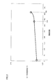
- FIG. It is a figure which shows the relationship between a heater resistance value and the film forming frequency.
- FIG. 1 is a diagram showing a configuration of a crystal growth apparatus 1 to which a heater deterioration determination apparatus according to an embodiment of the present invention is applied.
- FIG. 1 shows an overall configuration of a crystal growth apparatus 1 (also referred to as MOCVD apparatus 1) by a MOCVD (Metal Organic Chemical Vapor Deposition) method.
- MOCVD Metal Organic Chemical Vapor Deposition
- an MOCVD apparatus 1 is used for growing a thin film of a III-V group semiconductor crystal such as InGaAs (indium gallium arsenide), InGaP (indium gallium phosphide), InGaN (indium gallium nitride) on a substrate.
- the MOCVD apparatus 1 includes a reaction vessel 10, a susceptor 11, a heater 13, a heater power supply 51, a shower head 20, a source gas supply source (not shown), a cooling pump (not shown), a gas exhaust unit 40, and a current detection unit 81. , A voltage detection unit 82, a temperature sensor TS1, a temperature detection unit 83, a control unit 93, and a display unit 94.
- the susceptor 11 is a mounting table for holding a plurality of substrates SUB soaking, and is provided near the center in the reaction vessel.
- the surface temperature of the substrate SUB is detected by a radiation thermometer (not shown).
- a heater 13 is provided below the susceptor 11, for heating the substrate SUB placed on the susceptor 11 via the susceptor 11.
- a resistance heater using molybdenum disilicide or the like is used as the heater 13 .
- a heater power supply 51 for supplying electric power to the heater 13 is provided outside the reaction vessel 10.
- the shower head 20 is provided on the upper part of the substrate SUB so as to face the susceptor 11 and uniformly irradiates the group III gas (organic metal gas) and the group V gas supplied from the source gas supply source to the substrate.
- the shower head 20 is cooled by a refrigerant (for example, water) supplied from a cooling pump so that the temperature of the front surface portion 21 of the shower head 20 does not rise due to radiant heat from the susceptor 11. Excess source gas that has not been used for crystal growth is exhausted from the gas exhaust unit 40.
- the temperature sensor TS1 is, for example, a thermocouple, and is provided for measuring the temperature of the heater 13.
- the temperature detector 83 detects the temperature of the heater 13 based on the output of the temperature sensor TS1.
- the detection result of the temperature detection unit 83 is output to the control unit 93.
- the current detector 81 and the voltage detector 82 detect the current and voltage of the energized heater 13, respectively. Detection results by the current detection unit 81 and the voltage detection unit 82 are output to the control unit 93.
- the control unit 93 includes a PLC (Programmable Logic Controller) as a main control device.
- the PLC sequence-controls the MOCVD apparatus 1 according to a preprogrammed procedure (referred to as a recipe).
- Control unit 93 further determines deterioration of heater 13 based on detection results of current detection unit 81, voltage detection unit 82, and temperature detection unit 83. That is, the control unit 93 also functions as a deterioration determination device for the resistance heater 13.
- the deterioration determination program is incorporated in the PLC control program.
- the display unit 94 is composed of a touch panel and also serves as an input unit.
- the display unit 94 functions as a user interface for inputting system parameters, recipes, and the like.
- the deterioration determination procedure executed by the controller 93 is based on the following examination by the inventors of the present invention. That is, according to the study by the inventors, the resistance value of the heater until the heater is turned off, as shown in FIG. 2, the resistance value of the heater gradually increases and the heater is turned off as the number of film formation increases. It turned out to be a rising curve before.
- the ratio or deviation between the initial resistance value of the heater and the resistance value immediately before the heater was turned off did not change at any temperature.
- the 332th resistance value / first resistance value is all 1.08
- the 408th resistance value / the first resistance value was 1.15.
- a linear equation serving as a reference representing the relationship between the heater temperature and the heater resistance value is determined in the initial use state of the resistance heater.
- the first resistance value is calculated by applying the temperature of the energized heater to this linear equation, and the first resistance value is calculated from the current value and voltage value of the energized heater detected during the deterioration determination.
- a resistance value of 2 is calculated. Then, when the deviation between the first resistance value and the second resistance value or the ratio of the second resistance value to the first resistance value exceeds the threshold value, it is determined that the resistance heater has deteriorated.
- the threshold value used for the deterioration determination can be set to a constant value regardless of the heater temperature.
- Reference data a set of reference temperature and reference resistance value (collectively referred to as reference data) is acquired.
- the acquisition of the reference data is performed when the heater 13 is in a new state such as immediately after the heater 13 is replaced.
- the reference data it is necessary to energize the resistance heater.
- the reference data may be obtained by energizing the resistance heater separately from the crystal growth. Reference data may be acquired when the temperature is raised.
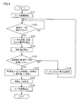
- FIG. 4 is a flowchart showing a procedure for determining a reference resistance-temperature characteristic.
- the reference data is obtained by energizing the resistance heater separately from the crystal growth.
- step S101 energization from the heater power supply 51 to the heater is started under the control of the control unit 93.
- the control unit 93 causes the temperature detection unit 83, the current detection unit 81, and the voltage detection unit.
- the temperature, current value, and voltage value of the heater 13 are detected by 82 (step S103).
- the temperature, current and voltage of the heater 13 may be measured based on a command from the control unit 93 without depending on the user input.
- the temperature, current, and voltage of the heater 13 may be measured when a predetermined time elapses after the temperature of the heater 13 reaches a predetermined set temperature.
- the in-plane distribution of the substrate temperature measured by the radiation thermometer is within ⁇ 1 ° C. after the temperature of the heater 13 reaches a predetermined set temperature, the temperature, current and voltage of the heater 13 are measured. It may be.
- the controller 93 calculates the resistance value of the heater using the detected current value and voltage value of the heater 13 (step S104).
- steps S102 to S104 are repeated until a necessary number (at least two) of reference data (heater temperature and resistance value) is acquired (that is, until YES in step S105).
- reference data that is, until YES in step S105.
- the set temperature of the heater 13 that is, the input power to the heater 13 is changed (step S106).
- a (Y1-Y2) / (X1-X2) (2)
- b Y1-X1 ⁇ (Y1-Y2) / (X1-X2) (3)
- a and b can be obtained by the least square method.
- the reference temperatures X1 and X2 are preferably set so as to be close to the crystal growth temperature (for example, the crystal growth temperature is included between X1 and X2).
- the resistance value of the resistance heater usually shows a metallic temperature dependence (a relationship in which the resistance is approximately proportional to the temperature). However, if X1 and X2 are set near the film forming temperature, the resistance value is completely linear. Even if it is a relationship, the error is small.
- the control unit 93 stores the calculated parameters a and b in the built-in memory (step S108). Thereafter, the energization to the heater 13 is stopped and the process ends (S109).
- FIG. 5 is a diagram illustrating an example of a screen of the display unit 94 when the reference data is acquired.
- the current temperature (° C.) of the heater 13 detected by the temperature detector 83 and the set temperature (° C.) of the heater 13 are shown in the upper left of the screen. .
- buttons “Measure 1” and “Measure 2” for the user to input the measurement timing of the reference data to the PLC are arranged.
- a measured temperature 1 detected when the user presses the “Measure 1” button and a measured resistance value 1 calculated from the heater voltage and heater current detected at the same timing are shown.
- a measured temperature 2 detected when the user presses the “Measure 2” button and a measured resistance value 2 calculated from the heater voltage and heater current detected at the same timing are shown.
- the resistance value change rate ( ⁇ / ° C.) obtained from the measurement data that is, the value of the parameter “a” in the above-described equation (2) is also shown.
- the reference data is detected, for example, when the temperature of the heater 13 reaches around 1000 ° C. and around 1200 ° C.
- the temperature, current value, and voltage value of the heater 13 in FIG. 1 are detected by the temperature detection unit 83, the current detection unit 81, and the voltage detection unit 82, respectively.
- the controller 93 calculates the first resistance value by applying the temperature of the heater 13 detected at the time of this determination to the linear equation of the above equation (1). Furthermore, the controller 93 calculates a second resistance value from the current value and voltage value of the heater 13 detected at the time of this determination.
- the controller 93 determines that the resistance heater has deteriorated when the deviation between the calculated first resistance value and the second resistance value or the ratio of the second resistance value to the first resistance value exceeds a threshold value. .
- This threshold value is obtained by multiplying the first resistance value by a predetermined allowable change rate.
- the allowable change rate is set to a constant value regardless of the temperature of the heater 13.
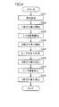
- FIG. 6 is a flowchart showing an outline of the operation of the crystal growth apparatus 1 of FIG. 1 during crystal growth.
- control program control procedure is also referred to as a recipe
- PLC control unit 93
- the controller 93 introduces a group V gas into the reaction vessel 10 through the shower head 20 (step S202). Subsequently, energization to the heater 13 is started (step S203). When the substrate temperature reaches the temperature at the time of film formation, the controller 93 introduces the group III gas into the reaction vessel 10 through the shower head 20 (step S204). Thus, film formation is started.
- the controller 93 determines the deterioration of the heater during the film formation (step S205). When the predetermined film formation time has elapsed, the introduction of the group III gas is stopped and the film formation is completed (step S206). After the film formation is completed, the power supplied to the heater 13 is gradually reduced, and the energization to the heater 13 is eventually stopped (step S207). Further, the introduction of the group V gas into the reaction vessel 10 is stopped.
- FIG. 7 is a diagram showing an example of a system parameter setting screen displayed on the display unit 94.
- the allowable change rate of the heater resistance value is set as one of the system parameters.
- a value obtained by multiplying the input allowable change rate by the reference resistance value represented by the above-described equation (1) is used as a threshold value (allowable deviation). That is, when the deviation between the resistance value of the heater 13 detected at the time of determination and the reference resistance value expressed by the equation (1) changes beyond the allowable deviation, it is determined that the abnormality is present.
- FIG. 8 is a diagram showing the relationship between the heater resistance value and the number of film formations.
- the heater temperature during film formation is constant for simplicity.
- the number of times of film formation is N or more and the resistance value is Rth or more.
- FIG. 9 is a diagram illustrating an example of a recipe creation screen displayed on the display unit 94.
- Recipes are executed in the order of step numbers (Steps) shown in the A column.
- LSn n is a number
- the process is repeated n times up to the step number where LE is written.
- a pair of LSn and LE constitutes one set of loops.
- step 6 to step 10 are the first loop (repetition number: 3 times)
- step 7 to step 9 are the second loop (repetition number: 2 times). That is, it is a multiple loop in which the second loop is included in the first loop.
- Column D is a column for describing a comment
- column E shows the execution time (Time) of each step in a format of MM: SS: 0 (minute: second).
- the controller 93 determines the deterioration of the heater 13. As a result of the deterioration determination, when the heater resistance value exceeds the threshold value, the control unit 93 displays the heater abnormality on the display unit 94 in FIG. This deterioration determination can be performed in real time during film formation.
- FIG. 10 is a flowchart showing the heater deterioration determination procedure shown in step S205 of FIG.
- control unit 93 performs temperature detection unit 83, current detection unit 81, and voltage detection unit 82 for a predetermined time (for example, 1 minute) set in a recipe.
- a predetermined time for example, 1 minute
- step S302 When the predetermined time has elapsed (YES in step S302), the controller 93 averages the measured temperature, current value, and voltage value of the heater 13 (step S303). And the control part 93 calculates the present resistance value from the average value of an electric current, and the average value of a voltage (step S304).
- the controller 93 calculates a deviation between the current resistance value obtained in step S304 and the reference resistance value obtained in step S305 or a ratio of the current resistance value to the reference resistance value (step S306). If the calculated deviation or ratio exceeds a predetermined allowable value (threshold) (step S307), an abnormality (deterioration of the heater) is displayed on the display unit 94 (step S308).
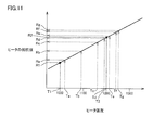
- FIG. 11 is a diagram showing the relationship between the heater temperature and the resistance value of the heater. Referring to FIG. 11, it is assumed that reference resistance values R1 and R2 are detected in advance at heater temperatures T1 and T2, respectively.
- the heater temperature during film formation is not constant because it varies depending on the gas composition, gas flow rate, film thickness, and the like. For example, assuming that the heater temperatures are different from Ta to Tg in FIG. 11 for each film formation, in the conventional method, at least a reference resistance corresponding to the heater temperatures Ta to Tg is acquired in advance and stored as a table in the memory. I had to remember it.
- the deterioration determination method since a linear expression representing the relationship between the heater temperature and the heater resistance value is used, there are at least two sets of reference measurement data (a set of reference temperature and resistance value). For example, the reference resistance values Ra to Rg corresponding to the heater temperatures Ta to Tg at the time of film formation can be accurately estimated.
- the method according to this embodiment is simpler than the prior art and does not require a memory capacity. For this reason, this deterioration determination method can be easily incorporated into a control program for PLC normally used in a crystal growth apparatus.
- the MOCVD apparatus has been described as an example.
- the method according to this embodiment includes other methods such as sputtering and vacuum deposition, as well as other CVD apparatuses that do not use an organic metal gas. It can be applied to the film forming apparatus.
- the method according to this embodiment can be applied to a semiconductor device other than the film forming apparatus, for example, an annealing apparatus.
Landscapes
- Chemical & Material Sciences (AREA)
- General Chemical & Material Sciences (AREA)
- Chemical Kinetics & Catalysis (AREA)
- Engineering & Computer Science (AREA)
- Materials Engineering (AREA)
- Mechanical Engineering (AREA)
- Metallurgy (AREA)
- Organic Chemistry (AREA)
- Investigating Or Analyzing Materials By The Use Of Electric Means (AREA)
- Chemical Vapour Deposition (AREA)
Abstract
抵抗加熱ヒータ(13)の劣化検出装置において、制御部(93)は、通電中の抵抗加熱ヒータの温度が第1の温度のときに検出された抵抗加熱ヒータの電流値および電圧値と、通電中の抵抗加熱ヒータの温度が第1の温度と異なる第2の温度のときに検出された抵抗加熱ヒータの電流値および電圧値とに少なくとも基づいて、抵抗加熱ヒータの温度と抵抗加熱ヒータの抵抗値との間の関係を表わす直線式を決定する。制御部は、この直線式を決定した後である判定時に検出された通電中の抵抗加熱ヒータの温度を、この直線式に当てはめることによって第1の抵抗値を算出し、上記の判定時に検出された通電中の抵抗加熱ヒータの電流値および電圧値から第2の抵抗値を算出する。そして、制御部は、第1の抵抗値と第2の抵抗値との偏差または第1の抵抗値に対する第2の抵抗値の比が閾値を超えたとき抵抗加熱ヒータが劣化したと判定する。
Description
この発明は、抵抗加熱ヒータの劣化検出装置および方法に関し、特に結晶成長装置などの半導体製造装置に用いられる抵抗加熱ヒータの劣化検出装置および方法に関する。
抵抗加熱ヒータは均一な加熱に適しており、MOCVD(Metal Organic Chemical Vapor Deposition)装置などの結晶成長装置における基板加熱にしばしば用いられる。結晶成長装置用の抵抗加熱ヒータの材料として、たとえば、強度や耐酸化性に優れた二ケイ化モリブデンが代表的である。
抵抗加熱ヒータは、使用に伴って日々劣化していく。MOCVD装置の場合に抵抗加熱ヒータが劣化する原因は、サセプタから下方へ流れ込むガスの中の原料ガスが、高温のヒータと反応し、ヒータを腐食させるためである。
ヒータが劣化すると、最悪の場合にはヒータの断線に至る。突然ヒータが断線すると、ヒータ交換作業のみならず、新たに取付けたヒータを脱ガス処理したり、ヒータに供給する電力と基板温度との関係を再測定したりする作業が必要になる。このような作業が突然生じると生産計画が守れなくなるおそれが生じる。
生産計画に影響しないようにするためには、抵抗加熱ヒータの劣化の程度を検出して、ヒータの交換時期を予測できることが望ましい。抵抗加熱ヒータの劣化検出装置の一例として、たとえば、特開2004-319953号公報(特許文献1)に記載された装置が知られている。
この文献に記載された劣化検出装置は、電流検出手段、電圧検出手段、温度検出手段、テーブルメモリ、およびCPUを含む。電流検出手段は、商用電源によって加熱されたヒータに流れる電流のレベルを検出する。電圧検出手段は、ヒータに印加される電圧のレベルを検出する。温度検出手段は、ヒータ温度を検出する。テーブルメモリは、ヒータの製造時の抵抗を算出するための抵抗温度係数を記憶してある。CPUは、電圧検出手段および電流検出手段による各検出結果に基づいてヒータの検査時の抵抗を算出するとともに、温度検出手段の検出結果とテーブルメモリに記憶してある抵抗温度係数とに基づいてヒータの基準時の抵抗を算出し、ヒータの検査時の抵抗とヒータの基準時の抵抗とに基づいてヒータの劣化の程度を割り出す。ここで、テーブルメモリは、この文献の図3に記載されるように、ヒータの固有の識別番号と、ヒータの抵抗温度係数と、ヒータの長さと、ヒータの断面積と、ヒータの基準時の抵抗、たとえば製造時の基準抵抗とを一組で記憶してあるメモリである。抵抗温度係数は、同図の場合には、20℃、850℃、1000℃に対する値が記憶されている。
抵抗加熱ヒータに用いられる二ケイ化モリブデンなどの抵抗値は、常温で非常に小さく高温になると大きくなるというように、温度依存性がある。このため、上記の特許文献のように基準時のヒータの抵抗値と検査時のヒータの抵抗値との比較によって劣化判定を行なう場合には、基準時のヒータの温度と検査時の抵抗の温度とを同一にする必要がある。上記の特許文献の場合には、複数の温度に対応して抵抗温度係数が予めテーブルメモリに記憶され、この係数を用いて、基準時の温度が検査時の温度に等しくなるように基準時の抵抗値が換算される。
ところで、結晶成長装置に用いられる抵抗加熱ヒータの劣化判定は、効率上は、結晶成長中に行なわれるのが望ましい。しかしながら、結晶成長中のヒータ温度は、原料ガスの成分や基板上に製膜される材料の膜厚などによって変化し、一定には定まらない。このため、結晶成長中にヒータの劣化判定を行なおうとうすると、結晶成長中に取り得る全温度に対して、予め基準抵抗値(上記の特許文献の場合には抵抗温度係数)を検出しておく必要があり、煩雑である。
したがって、この発明の目的は、抵抗加熱ヒータの劣化判定を従来よりも簡便に行なうことができる劣化判定装置および方法を提供することである。
この発明は、一局面において、抵抗加熱ヒータの劣化検出装置であって、抵抗加熱ヒータに流れる電流を検出する電流検出部と、抵抗加熱ヒータにかかる電圧を検出する電圧検出部と、抵抗加熱ヒータの温度を検出する温度検出部と、制御部とを備える。制御部は、通電中の抵抗加熱ヒータの温度が第1の温度のときに検出された抵抗加熱ヒータの電流値および電圧値と、通電中の抵抗加熱ヒータの温度が第1の温度と異なる第2の温度のときに検出された抵抗加熱ヒータの電流値および電圧値とに少なくとも基づいて、抵抗加熱ヒータの温度と抵抗加熱ヒータの抵抗値との間の関係を表わす直線式を決定する。制御部は、この直線式を決定した後である判定時に検出された通電中の抵抗加熱ヒータの温度を、この直線式に当てはめることによって第1の抵抗値を算出し、上記の判定時に検出された通電中の抵抗加熱ヒータの電流値および電圧値から第2の抵抗値を算出する。そして、制御部は、第1の抵抗値と第2の抵抗値との偏差または第1の抵抗値に対する第2の抵抗値の比が閾値を超えたとき抵抗加熱ヒータが劣化したと判定する。
好ましくは、抵抗加熱ヒータは、結晶成長用の基板加熱に用いられる。上記の判定時は、結晶成長中の時間帯に含まれる。
好ましくは、結晶成長中の抵抗加熱ヒータの温度は、上記の第1の温度と第2の温度との間に含まれる。
好ましくは、上記の閾値は、判定時の抵抗加熱ヒータの温度によらず一定の値である。
この発明は他の局面において、抵抗加熱ヒータの劣化検出方法であって、通電中の抵抗加熱ヒータの温度が第1の温度のときに抵抗加熱ヒータの電流値および電圧値を検出するステップと、通電中の抵抗加熱ヒータの温度が第1の温度と異なる第2の温度のときに抵抗加熱ヒータの電流値および電圧値とを検出するステップと、第1および第2の温度のときに検出された抵抗加熱ヒータの電流値および電圧値に少なくとも基づいて、抵抗加熱ヒータの温度と抵抗加熱ヒータの抵抗値との間の関係を表わす直線式を決定するステップと、この直線式を決定した後である判定時に、通電中の抵抗加熱ヒータの電流値、電圧値および温度を検出するステップと、この判定時に検出された抵抗加熱ヒータの温度を上記の直線式に当てはめることによって第1の抵抗値を算出するステップと、上記の判定時に検出された抵抗加熱ヒータの電流値および電圧値から第2の抵抗値を算出するステップと、第1の抵抗値と第2の抵抗値との偏差または第1の抵抗値に対する第2の抵抗値の比が閾値を超えたとき抵抗加熱ヒータが劣化したと判定するステップとを備える。
この発明は他の局面において、抵抗加熱ヒータの劣化検出方法であって、通電中の抵抗加熱ヒータの温度が第1の温度のときに抵抗加熱ヒータの電流値および電圧値を検出するステップと、通電中の抵抗加熱ヒータの温度が第1の温度と異なる第2の温度のときに抵抗加熱ヒータの電流値および電圧値とを検出するステップと、第1および第2の温度のときに検出された抵抗加熱ヒータの電流値および電圧値に少なくとも基づいて、抵抗加熱ヒータの温度と抵抗加熱ヒータの抵抗値との間の関係を表わす直線式を決定するステップと、この直線式を決定した後である判定時に、通電中の抵抗加熱ヒータの電流値、電圧値および温度を検出するステップと、この判定時に検出された抵抗加熱ヒータの温度を上記の直線式に当てはめることによって第1の抵抗値を算出するステップと、上記の判定時に検出された抵抗加熱ヒータの電流値および電圧値から第2の抵抗値を算出するステップと、第1の抵抗値と第2の抵抗値との偏差または第1の抵抗値に対する第2の抵抗値の比が閾値を超えたとき抵抗加熱ヒータが劣化したと判定するステップとを備える。
この発明によれば、抵抗加熱ヒータの温度と抵抗加熱ヒータの抵抗値との間の関係を表わす直線式を決定し、判定時に検出された抵抗加熱ヒータの温度をこの直線式に当てはめることによって基準となる抵抗値を算出するので、抵抗加熱ヒータの劣化判定を従来よりも簡便に行なうことができる。
以下、この発明の実施の形態について図面を参照して詳しく説明する。なお、同一または相当する部分には同一の参照符号を付して、その説明を繰返さない。
[結晶成長装置の構成]
図1は、この発明の実施の一形態によるヒータの劣化判定装置が適用される結晶成長装置1の構成を示す図である。図1にはMOCVD(Metal Organic Chemical Vapor Deposition)法による結晶成長装置1(MOCVD装置1とも記載する)の全体構成が示される。
図1は、この発明の実施の一形態によるヒータの劣化判定装置が適用される結晶成長装置1の構成を示す図である。図1にはMOCVD(Metal Organic Chemical Vapor Deposition)法による結晶成長装置1(MOCVD装置1とも記載する)の全体構成が示される。
図1を参照して、MOCVD装置1は、InGaAs(インジウムガリウム砒素)、InGaP(インジウムガリウムリン)、InGaN(窒化インジウムガリウム)などのIII-V族半導体結晶の薄膜を基板上に成長させるための装置である。MOCVD装置1は、反応容器10、サセプタ11、ヒータ13、ヒータ電源51、シャワーヘッド20、原料ガス供給源(図示せず)、冷却ポンプ(図示せず)、ガス排気部40、電流検出部81、電圧検出部82、温度センサTS1、温度検出部83、制御部93、および表示部94を含む。
サセプタ11は、複数の基板SUBを均熱保持するための載置台であり、反応容器内の中央付近に設けられる。基板SUBの表面温度は、放射温度計(図示せず)によって検出される。
サセプタ11の下方には、サセプタ11に載置された基板SUBをサセプタ11を介して加熱するヒータ13が設けられる。ヒータ13として、二ケイ化モリブデンなどを用いた抵抗加熱ヒータが用いられる。反応容器10の外部には、ヒータ13に電力を供給するためのヒータ電源51が設けられる。
シャワーヘッド20は、サセプタ11に対向して基板SUBの上部に設けられ、原料ガス供給源から供給されたIII族ガス(有機金属ガス)およびV族ガスを基板に均一に照射する。シャワーヘッド20の前面部21の温度がサセプタ11からの輻射熱によって上昇しないように、シャワーヘッド20は、冷却ポンプから供給された冷媒(たとえば、水)によって冷却される。結晶成長に用いられなかった余分の原料ガスなどはガス排気部40から排気される。
温度センサTS1は、たとえば熱電対であり、ヒータ13の温度測定のために設けられる。温度検出部83は、温度センサTS1の出力に基づいてヒータ13の温度を検出する。温度検出部83の検出結果は、制御部93に出力される。
電流検出部81および電圧検出部82は、通電中のヒータ13の電流および電圧をそれぞれ検出する。電流検出部81および電圧検出部82による検出結果は、制御部93に出力される。
制御部93は、主制御機器としてのPLC(Programmable Logic Controller)を含む。PLCは、予めプログラムされた手順(レシピと称する)に従って、MOCVD装置1をシーケンス制御する。制御部93は、さらに、電流検出部81、電圧検出部82、および温度検出部83の検出結果に基づいてヒータ13の劣化判定を行なう。すなわち、制御部93は、抵抗加熱ヒータ13の劣化判定装置としても機能する。劣化判定用のプログラムはPLC用の制御プログラムに組み込まれている。
表示部94は、タッチパネルによって構成され、入力部も兼ねる。表示部94は、システム・パラメータやレシピなどを入力するためのユーザインタフェースとして機能する。
[劣化判定手順の概要]
制御部93によって実行される劣化判定手順は、この発明の発明者らによる次のような検討に基づいたものである。すなわち、発明者らの検討によれば、ヒータが切れるまでのヒータの抵抗値は、図2に示すように、製膜回数が増加するにつれて、ヒータの抵抗値が徐々に増加し、ヒータが切れる前では上昇カーブすることがわかった。
制御部93によって実行される劣化判定手順は、この発明の発明者らによる次のような検討に基づいたものである。すなわち、発明者らの検討によれば、ヒータが切れるまでのヒータの抵抗値は、図2に示すように、製膜回数が増加するにつれて、ヒータの抵抗値が徐々に増加し、ヒータが切れる前では上昇カーブすることがわかった。
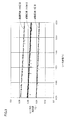
また、図2の製膜回数の1回目(ヒータ初期)、332回目(ヒータ抵抗値の上昇カーブ開始時)、408回目(ヒータ切れる直前)での、抵抗加熱ヒータの温度と抵抗加熱ヒータの抵抗値との間の関係を調べたところ、図3に示すように、製膜回数にかかわらずそれぞれ直線で近似できることがわかった。
さらに、どの温度でもヒータ初期の抵抗値とヒータが切れる直前の抵抗値との比または偏差は変わらないこともわかった。例えば、ヒータの温度1100℃と1150℃と1200℃と1250℃での、332回目の抵抗値÷1回目の抵抗値の値はすべて1.08で、408回目の抵抗値÷1回目の抵抗値の値はすべて1.15であった。
上記の検討結果から、この実施の形態による劣化判定手順では、まず抵抗加熱ヒータの使用初期の状態で、ヒータの温度とヒータの抵抗値との間の関係を表わす基準となる直線式が決定される。その後の劣化判定時において、通電中のヒータの温度を、この直線式に当てはめることによって第1の抵抗値が算出され、この劣化判定時に検出された通電中のヒータの電流値および電圧値から第2の抵抗値が算出される。そして、第1の抵抗値と第2の抵抗値との偏差または第1の抵抗値に対する第2の抵抗値の比が閾値を超えたとき、抵抗加熱ヒータが劣化したと判定される。劣化判定に用いる閾値は、ヒータの温度によらず一定の値に設定できる。
[基準となる抵抗-温度特性の決定]
抵抗加熱ヒータ13について基準となる抵抗-温度特性を決定するために、基準温度および基準抵抗値の組(これらを併せて基準データと称する)を取得する。この基準データの取得は、ヒータ13の交換直後など、ヒータ13が新品状態のときに行なわれる。基準データを取得するためには抵抗加熱ヒータに通電する必要があるが、結晶成長とは別に抵抗加熱ヒータに通電することによって基準データを取得してもよいし、結晶成長のために基板温度を昇温する際に基準データを取得してもよい。
抵抗加熱ヒータ13について基準となる抵抗-温度特性を決定するために、基準温度および基準抵抗値の組(これらを併せて基準データと称する)を取得する。この基準データの取得は、ヒータ13の交換直後など、ヒータ13が新品状態のときに行なわれる。基準データを取得するためには抵抗加熱ヒータに通電する必要があるが、結晶成長とは別に抵抗加熱ヒータに通電することによって基準データを取得してもよいし、結晶成長のために基板温度を昇温する際に基準データを取得してもよい。
図4は、基準となる抵抗-温度特性を決定する手順を示すフローチャートである。図4では、結晶成長とは別に抵抗加熱ヒータに通電することによって基準データが取得される。
まず、ステップS101で、制御部93の制御に従って、ヒータ電源51からヒータへの通電が開始される。
ヒータ13の温度が所定の設定温度になった後、測定開始を示す入力をユーザから受けると(ステップS102でYES)、制御部93は、温度検出部83、電流検出部81、および電圧検出部82によって、ヒータ13の温度、電流値および電圧値を検出する(ステップS103)。
ヒータ13の温度、電流および電圧の測定は、ユーザの入力によらずに、制御部93の指令に基づいて行なわれるようにしてもよい。たとえば、ヒータ13の温度が所定の設定温度になってから所定の時間が経過したら、ヒータ13の温度、電流および電圧を測定するようにしてもよい。もしくは、ヒータ13の温度が所定の設定温度に到達した後、放射温度計によって測定される基板温度の面内分布が±1℃以内になったら、ヒータ13の温度、電流および電圧を測定するようにしてもよい。
制御部93は、検出したヒータ13の電流値および電圧値を用いて、ヒータの抵抗値を算出する(ステップS104)。
上記のステップS102~S104は、必要な数(少なくとも2個)の基準データ(ヒータの温度と抵抗値)が取得されるまで(すなわち、ステップS105でYESとなるまで)繰返される。新たな基準データを取得する際には、ヒータ13の設定温度(すなわち、ヒータ13への投入電力)が変更される(ステップS106)。
基準データの取得が終了すると、制御部93は、ヒータ13の温度とヒータ13の抵抗値との相関を示す直線式、すなわち、
Y=aX+b(ただし、X:温度、Y:抵抗値) …(1)
のパラメータ(係数)a,bを決定する。基準データとして、2つの温度X1,X2とそれぞれ対応する抵抗値Y1,Y2とが得られているときは、
a=(Y1-Y2)/(X1-X2) …(2)
b=Y1-X1・(Y1-Y2)/(X1-X2) …(3)
によって、a,bを求めることができる。3組以上の温度と抵抗値との関係が得られているときは、最小二乗法によってa,bを求めることができる。
Y=aX+b(ただし、X:温度、Y:抵抗値) …(1)
のパラメータ(係数)a,bを決定する。基準データとして、2つの温度X1,X2とそれぞれ対応する抵抗値Y1,Y2とが得られているときは、
a=(Y1-Y2)/(X1-X2) …(2)
b=Y1-X1・(Y1-Y2)/(X1-X2) …(3)
によって、a,bを求めることができる。3組以上の温度と抵抗値との関係が得られているときは、最小二乗法によってa,bを求めることができる。
上記の基準温度X1,X2は、結晶成長温度の近傍となるように(たとえば、結晶成長温度がX1とX2との間に含まれるように)設定されるのが望ましい。抵抗加熱ヒータの抵抗値は通常、金属的な温度依存性(抵抗が温度にほぼ比例する関係)を示すが、X1,X2が製膜温度の近傍に設定されていれば、完全に直線的な関係であるとしても誤差は小さい。
制御部93は、算出したパラメータa,bを内蔵のメモリに記憶する(ステップS108)。その後、ヒータ13への通電が停止されて処理が終了する(S109)。
図5は、基準データの取得時おける表示部94の画面の一例を示す図である。
図1、図5を参照して、画面の左上には、温度検出部83によって検出されている現在のヒータ13の温度(℃)と、ヒータ13の設定温度(℃)とが示されている。
図1、図5を参照して、画面の左上には、温度検出部83によって検出されている現在のヒータ13の温度(℃)と、ヒータ13の設定温度(℃)とが示されている。
画面の右上には、電圧検出部82によって検出されたヒータ13の電圧値(V)と、電流検出部81によって検出されたヒータ13を流れる電流値(A)と、検出された電流および電圧から算出されたヒータ13の抵抗値(Ω)と、ヒータ電源51からヒータ13に供給される電力(W)とが示されている。
画面の中央付近には、ユーザが基準データの測定タイミングをPLCに入力するためのボタン「測定1」「測定2」(参照符号101,102)が配置される。
画面の左下には、ユーザが「測定1」ボタンを押圧したタイミングで検出された測定温度1と、同じタイミングで検出されたヒータ電圧およびヒータ電流から算出された測定抵抗値1とが示される。画面の右下には、ユーザが「測定2」ボタンを押圧したタイミングで検出された測定温度2と、同じタイミングで検出されたヒータ電圧およびヒータ電流から算出された測定抵抗値2とが示される。さらに、こられの測定データから求めた抵抗値変化率(Ω/℃)、すなわち前述の式(2)のパラメータ「a」の値も示される。図5に示すように、基準データは、たとえば、ヒータ13の温度が1000℃付近と1200℃付近になったときに検出される。
[ヒータの劣化判定手順]
ヒータの劣化判定は、上記の抵抗-温度特性を決定した後の結晶成長時に行なわれる。
ヒータの劣化判定は、上記の抵抗-温度特性を決定した後の結晶成長時に行なわれる。
劣化判定時には、まず、図1のヒータ13の温度、電流値および電圧値が、温度検出部83、電流検出部81および電圧検出部82によってそれぞれ検出される。制御部93は、この判定時に検出されたヒータ13の温度を上式(1)の直線式に当てはめることによって第1の抵抗値を算出する。さらに制御部93は、この判定時に検出されたヒータ13の電流値および電圧値から第2の抵抗値を算出する。制御部93は、算出した第1の抵抗値と第2の抵抗値との偏差または第1の抵抗値に対する第2の抵抗値の比が閾値を超えたとき抵抗加熱ヒータが劣化したと判定する。この閾値は、第1の抵抗値に所定の許容変化率を乗算することによって得られる。許容変化率はヒータ13の温度によらず一定の値に設定される。
図6は、結晶成長時における図1の結晶成長装置1の動作の概略を示すフローチャートである。
図6の最初のステップS201で、制御部93に内蔵されたメモリからシステム・パラメータなどが読み出されることによって、装置の初期設定が行なわれる。続いて、制御部93に内蔵されたメモリから予め作成された制御プログラム(制御手順のことをレシピとも称する)が読み出され、読み出されたレシピに従って制御部93(PLC)が制御を開始する。
まず、制御部93は、シャワーヘッド20を介してV族ガスを反応容器10内に導入する(ステップS202)。続いてヒータ13への通電が開始される(ステップS203)。基板温度が製膜時の温度に達すると、制御部93は、シャワーヘッド20を介してIII族ガスを反応容器10内に導入する(ステップS204)。これによって製膜が開始される。制御部93は、この製膜の途中でヒータの劣化判定を行なう(ステップS205)。所定の製膜時間が経過したら、III族ガスの導入が停止されることによって製膜が終了する(ステップS206)。製膜終了後、ヒータ13への供給電力は徐々に減少され、やがて、ヒータ13への通電が停止される(ステップS207)。さらに、V族ガスの反応容器10内への導入が停止される。
図7は、表示部94に表示されるシステム・パラメータの設定画面の一例を示す図である。ヒータ抵抗値の許容変化率は、システム・パラメータの1つとして設定されている。入力された許容変化率に前述の式(1)で表わされる基準抵抗値を乗算した値が閾値(許容偏差)として用いられる。すなわち、判定時に検出されたヒータ13の抵抗値と、式(1)で表わされる基準抵抗値との偏差が、この許容偏差を超えて変化したとき異常と判定される。
図8は、ヒータ抵抗値と製膜回数との関係を示す図である。図8では、簡単のために製膜時のヒータ温度は一定としている。
図8に示すように、製膜回数が増加するにつれて、ヒータの抵抗値が初期値Riniから徐々に増加する。図7に示した許容変化率をαとすると、許容偏差(閾値)はα×Riniで表わされる。したがって、制御部93は、ヒータの抵抗値Rが、(1+α)×Rini(=Rthとする)を超えると異常と判定する。図8では、製膜回数がN以上で抵抗値がRth以上となっている。
図9は、表示部94に表示されるレシピ作成画面の一例を示す図である。レシピは、A列に示されたステップ番号(Steps)の順に実行される。ただし、B列に示されたループ(Loop)欄にLSn(nは数字)が記載さているときには、LEが記載されているステップ番号まで処理がn回繰返される。LSnとLEとのペアで1組のループを構成する。図9の場合、ステップ6からステップ10までが第1のループ(繰返し回数:3回)であり、ステップ7からステップ9までが第2のループ(繰返し回数:2回)である。すなわち、第1のループの中に第2のループが入った多重ループとなっている。D列は、コメント(comment)の記載欄であり、E列には各ステップの実行時間(Time)がMM:SS:0(分:秒)のフォーマットで示される。
予めユーザがActionの欄に「resistance」を入力し、製膜時に実行ステップが「resistance」の入力されたステップ番号になると、制御部93はヒータ13の劣化判定を行なう。劣化判定の結果、閾値を超えてヒータの抵抗値が増加していたとき、制御部93は図1の表示部94にヒータの異常を表示する。この劣化判定は、製膜中にリアルタイムで行なうことができる。
図10は、図6のステップS205に示されたヒータの劣化判定手順を示すフローチャートである。
図10を参照して、劣化判定時には、まず、制御部93は、レシピで設定されている所定時間(たとえば、1分)の間、温度検出部83、電流検出部81、および電圧検出部82によって、ヒータ13の温度、電流値および電圧値を繰返して検出する(ステップS301)。
所定時間が経過すると(ステップS302でYES)、制御部93は、測定したヒータ13の温度、電流値および電圧値をそれぞれ平均化する(ステップS303)。そして、制御部93は、電流の平均値と電圧の平均値から現在の抵抗値を算出する(ステップS304)。
次に、制御部93は、前述の式(1)の相関式Y=aX+bの温度Xに、求めた温度の平均値を代入することにより、判定時のヒータ温度に対応する基準抵抗値を算出する(ステップS305)。
制御部93は、上記のステップS304で得られた現在の抵抗値と、ステップS305で得られた基準抵抗値との偏差または基準抵抗値に対する現在の抵抗値の比を算出し(ステップS306)、算出した偏差または比が所定の許容値(閾値)を超えていたら(ステップS307)、表示部94に異常(ヒータの劣化)を表示する(ステップS308)。
図11は、ヒータ温度とヒータの抵抗値との関係を示す図である。図11を参照して、予めヒータ温度T1,T2で基準となる抵抗値R1,R2がそれぞれ検出されているとする。
製膜中のヒータ温度は、ガス組成、ガス流量、および膜厚などによって変化するので一定にはならない。たとえば、製膜ごとに図11のTa~Tgのように異なるヒータ温度になっていたとすると、従来の方法では、少なくともヒータ温度Ta~Tgに対応する基準抵抗を予め取得し、メモリ中にテーブルとして記憶しておく必要があった。
この実施の形態による劣化判定方法によれば、ヒータ温度とヒータ抵抗値との関係を表わす直線式を利用するので、基準となる測定データ(基準温度と抵抗値との組)が少なくとも2組あれば、製膜時のヒータ温度Ta~Tgに対応する基準抵抗値Ra~Rgを正確に推定することができる。このように、この実施の形態による方法は、従来に比べて簡便でありかつメモリ容量も必要としない。このため、結晶成長装置に通常用いられるPLC用の制御プログラムにこの劣化判定方法を容易に組み込むことができる。
以上の実施の形態では、MOCVD装置を例に挙げて説明したが、この実施の形態による方法は、有機金属ガスを用いない他のCVD装置を始め、スパッタ法や真空蒸着法などの他の方式の製膜装置にも適用することができる。さらには、製膜装置以外の半導体装置、たとえばアニール装置などにも、この実施の形態による方法を適用することができる。
今回開示された実施の形態はすべての点で例示であって制限的なものでないと考えられるべきである。この発明の範囲は上記した説明ではなくて請求の範囲によって示され、請求の範囲と均等の意味および範囲内でのすべての変更が含まれることが意図される。
1 結晶成長装置(MOCVD装置)、10 反応容器、11 サセプタ、13 抵抗加熱ヒータ、20 シャワーヘッド、51 ヒータ電源、81 電流検出部、82 電圧検出部、83 温度検出部、93 制御部、94 表示部、SUB 基板、TS1 温度センサ。
Claims (5)
- 抵抗加熱ヒータに流れる電流を検出する電流検出部と、
前記抵抗加熱ヒータにかかる電圧を検出する電圧検出部と、
前記抵抗加熱ヒータの温度を検出する温度検出部と、
制御部とを備え、
前記制御部は、通電中の前記抵抗加熱ヒータの温度が第1の温度のときに検出された前記抵抗加熱ヒータの電流値および電圧値と、通電中の前記抵抗加熱ヒータの温度が前記第1の温度と異なる第2の温度のときに検出された前記抵抗加熱ヒータの電流値および電圧値とに少なくとも基づいて、前記抵抗加熱ヒータの温度と前記抵抗加熱ヒータの抵抗値との間の関係を表わす直線式を決定し、
前記制御部は、前記直線式を決定した後である判定時に検出された通電中の前記抵抗加熱ヒータの温度を、前記直線式に当てはめることによって第1の抵抗値を算出し、前記判定時に検出された通電中の前記抵抗加熱ヒータの電流値および電圧値から第2の抵抗値を算出し、
前記制御部は、前記第1の抵抗値と前記第2の抵抗値との偏差または前記第1の抵抗値に対する前記第2の抵抗値の比が閾値を超えたとき前記抵抗加熱ヒータが劣化したと判定する、抵抗加熱ヒータの劣化検出装置。 - 前記抵抗加熱ヒータは、結晶成長用の基板加熱に用いられ、
前記判定時は、結晶成長中の時間帯に含まれる、請求項1に記載の抵抗加熱ヒータの劣化検出装置。 - 結晶成長中の前記抵抗加熱ヒータの温度は、前記第1の温度と前記第2の温度との間に含まれる、請求項2に記載の抵抗加熱ヒータの劣化検出装置。
- 前記閾値は、前記判定時の前記抵抗加熱ヒータの温度によらず一定の値である、請求項1に記載の抵抗加熱ヒータの劣化検出装置。
- 通電中の抵抗加熱ヒータの温度が第1の温度のときに前記抵抗加熱ヒータの電流値および電圧値を検出するステップと、
通電中の前記抵抗加熱ヒータの温度が前記第1の温度と異なる第2の温度のときに前記抵抗加熱ヒータの電流値および電圧値とを検出するステップと、
前記第1および第2の温度のときに検出された前記抵抗加熱ヒータの電流値および電圧値に少なくとも基づいて、前記抵抗加熱ヒータの温度と前記抵抗加熱ヒータの抵抗値との間の関係を表わす直線式を決定するステップと、
前記直線式を決定した後である判定時に、通電中の前記抵抗加熱ヒータの電流値、電圧値および温度を検出するステップと、
前記判定時に検出された前記抵抗加熱ヒータの温度を前記直線式に当てはめることによって第1の抵抗値を算出するステップと、
前記判定時に検出された前記抵抗加熱ヒータの電流値および電圧値から第2の抵抗値を算出するステップと、
前記第1の抵抗値と前記第2の抵抗値との偏差または前記第1の抵抗値に対する前記第2の抵抗値の比が閾値を超えたとき前記抵抗加熱ヒータが劣化したと判定するステップとを備える、抵抗加熱ヒータの劣化検出方法。
Applications Claiming Priority (2)
| Application Number | Priority Date | Filing Date | Title |
|---|---|---|---|
| JP2011123145 | 2011-06-01 | ||
| JP2011-123145 | 2011-06-01 |
Publications (1)
| Publication Number | Publication Date |
|---|---|
| WO2012165174A1 true WO2012165174A1 (ja) | 2012-12-06 |
Family
ID=47259036
Family Applications (1)
| Application Number | Title | Priority Date | Filing Date |
|---|---|---|---|
| PCT/JP2012/062770 Ceased WO2012165174A1 (ja) | 2011-06-01 | 2012-05-18 | 抵抗加熱ヒータの劣化検出装置および方法 |
Country Status (2)
| Country | Link |
|---|---|
| TW (1) | TW201306640A (ja) |
| WO (1) | WO2012165174A1 (ja) |
Cited By (10)
| Publication number | Priority date | Publication date | Assignee | Title |
|---|---|---|---|---|
| WO2017061334A1 (ja) * | 2015-10-08 | 2017-04-13 | 株式会社ニューフレアテクノロジー | 気相成長装置および異常検出方法 |
| JP2020535646A (ja) * | 2017-09-25 | 2020-12-03 | エックス−ファブ・セミコンダクター・ファウンダリーズ・ゲーエムベーハーX−FAB Semiconductor Foundries GmbH | 加熱素子の破損を早期に認識するマルチゾーン縦型炉のリアルタイム監視 |
| JP2021002576A (ja) * | 2019-06-21 | 2021-01-07 | 東京エレクトロン株式会社 | プラズマ処理装置及びプラズマ処理方法 |
| EP3273809B1 (en) | 2015-03-26 | 2021-02-17 | Philip Morris Products S.a.s. | Heater management |
| WO2022163214A1 (ja) * | 2021-01-29 | 2022-08-04 | 住友電気工業株式会社 | ヒータ制御装置 |
| WO2022201983A1 (ja) * | 2021-03-25 | 2022-09-29 | 日立Astemo株式会社 | 内燃機関の制御装置 |
| JP2023066989A (ja) * | 2021-10-29 | 2023-05-16 | 株式会社ジェイテクトサーモシステム | ヒータ監視装置、熱処理装置、ヒータ監視方法、および、プログラム |
| JP2024119958A (ja) * | 2019-06-07 | 2024-09-03 | ワトロー エレクトリック マニュファクチュアリング カンパニー | 電気ヒーターを操作する制御システムを較正するための方法 |
| JP2025026870A (ja) * | 2017-08-10 | 2025-02-26 | ワットロー・エレクトリック・マニュファクチャリング・カンパニー | ヒータへの電力を制御するシステム及び方法 |
| US12523683B2 (en) | 2016-06-15 | 2026-01-13 | Watlow Electric Manufacturing Company | System and method for controlling power to a heater |
Families Citing this family (4)
| Publication number | Priority date | Publication date | Assignee | Title |
|---|---|---|---|---|
| JP2016162774A (ja) * | 2015-02-26 | 2016-09-05 | 株式会社Screenホールディングス | ヒータ異常検出装置、処理液供給装置、基板処理システム、およびヒータ異常検出方法 |
| JP2018174047A (ja) * | 2017-03-31 | 2018-11-08 | アズビル株式会社 | 劣化診断装置および方法 |
| DE102019003768A1 (de) * | 2019-05-29 | 2020-12-03 | Gentherm Gmbh | Vorrichtung zum Ermitteln der Temperatur einer Widerstandsheizeinrichtung |
| TWI841942B (zh) * | 2021-07-09 | 2024-05-11 | 日商歐姆龍股份有限公司 | 異常判定裝置、異常判定方法以及異常判定系統 |
Citations (3)
| Publication number | Priority date | Publication date | Assignee | Title |
|---|---|---|---|---|
| JP2006165200A (ja) * | 2004-12-06 | 2006-06-22 | Kokusai Electric Semiconductor Service Inc | 半導体製造装置における抵抗加熱ヒータの抵抗値検出装置、半導体製造装置における抵抗加熱ヒータの劣化診断装置及びネットワークシステム |
| JP2009141158A (ja) * | 2007-12-07 | 2009-06-25 | Noboru Naruo | 気相成長装置用ヒーター |
| JP2009281837A (ja) * | 2008-05-21 | 2009-12-03 | Tokyo Electron Ltd | 電力使用系の断線予測装置及び熱処理装置 |
-
2012
- 2012-05-18 WO PCT/JP2012/062770 patent/WO2012165174A1/ja not_active Ceased
- 2012-06-01 TW TW101119873A patent/TW201306640A/zh unknown
Patent Citations (3)
| Publication number | Priority date | Publication date | Assignee | Title |
|---|---|---|---|---|
| JP2006165200A (ja) * | 2004-12-06 | 2006-06-22 | Kokusai Electric Semiconductor Service Inc | 半導体製造装置における抵抗加熱ヒータの抵抗値検出装置、半導体製造装置における抵抗加熱ヒータの劣化診断装置及びネットワークシステム |
| JP2009141158A (ja) * | 2007-12-07 | 2009-06-25 | Noboru Naruo | 気相成長装置用ヒーター |
| JP2009281837A (ja) * | 2008-05-21 | 2009-12-03 | Tokyo Electron Ltd | 電力使用系の断線予測装置及び熱処理装置 |
Cited By (23)
| Publication number | Priority date | Publication date | Assignee | Title |
|---|---|---|---|---|
| EP3273809B1 (en) | 2015-03-26 | 2021-02-17 | Philip Morris Products S.a.s. | Heater management |
| US12075811B2 (en) | 2015-03-26 | 2024-09-03 | Philip Morris Products S.A. | Heater management |
| JP2017073498A (ja) * | 2015-10-08 | 2017-04-13 | 株式会社ニューフレアテクノロジー | 気相成長装置および異常検出方法 |
| TWI626331B (zh) * | 2015-10-08 | 2018-06-11 | 紐富來科技股份有限公司 | Gas phase growth device and abnormality detection method |
| WO2017061334A1 (ja) * | 2015-10-08 | 2017-04-13 | 株式会社ニューフレアテクノロジー | 気相成長装置および異常検出方法 |
| US12523683B2 (en) | 2016-06-15 | 2026-01-13 | Watlow Electric Manufacturing Company | System and method for controlling power to a heater |
| JP7771330B2 (ja) | 2017-08-10 | 2025-11-17 | ワットロー・エレクトリック・マニュファクチャリング・カンパニー | ヒータへの電力を制御するシステム及び方法 |
| JP2025026870A (ja) * | 2017-08-10 | 2025-02-26 | ワットロー・エレクトリック・マニュファクチャリング・カンパニー | ヒータへの電力を制御するシステム及び方法 |
| JP7271520B2 (ja) | 2017-09-25 | 2023-05-11 | エックス-ファブ・セミコンダクター・ファウンダリーズ・ゲーエムベーハー | 加熱素子の破損を早期に認識するマルチゾーン縦型炉のリアルタイム監視 |
| JP2020535646A (ja) * | 2017-09-25 | 2020-12-03 | エックス−ファブ・セミコンダクター・ファウンダリーズ・ゲーエムベーハーX−FAB Semiconductor Foundries GmbH | 加熱素子の破損を早期に認識するマルチゾーン縦型炉のリアルタイム監視 |
| JP2024119958A (ja) * | 2019-06-07 | 2024-09-03 | ワトロー エレクトリック マニュファクチュアリング カンパニー | 電気ヒーターを操作する制御システムを較正するための方法 |
| JP7676635B2 (ja) | 2019-06-07 | 2025-05-14 | ワトロー エレクトリック マニュファクチュアリング カンパニー | 電気ヒーターを操作する制御システムを較正するための方法 |
| US12328799B2 (en) | 2019-06-07 | 2025-06-10 | Watlow Electric Manufacturing Company | System and method for calibrating a control system operating an electric heater |
| JP7071946B2 (ja) | 2019-06-21 | 2022-05-19 | 東京エレクトロン株式会社 | プラズマ処理装置 |
| JP2021002576A (ja) * | 2019-06-21 | 2021-01-07 | 東京エレクトロン株式会社 | プラズマ処理装置及びプラズマ処理方法 |
| JP7494946B2 (ja) | 2021-01-29 | 2024-06-04 | 住友電気工業株式会社 | ヒータ制御装置 |
| JPWO2022163214A1 (ja) * | 2021-01-29 | 2022-08-04 | ||
| WO2022163214A1 (ja) * | 2021-01-29 | 2022-08-04 | 住友電気工業株式会社 | ヒータ制御装置 |
| JP2022150053A (ja) * | 2021-03-25 | 2022-10-07 | 日立Astemo株式会社 | 内燃機関の制御装置 |
| DE112022001765T5 (de) | 2021-03-25 | 2024-01-25 | Hitachi Astemo, Ltd. | Verbrennungsmotorsteuervorrichtung |
| WO2022201983A1 (ja) * | 2021-03-25 | 2022-09-29 | 日立Astemo株式会社 | 内燃機関の制御装置 |
| JP7591448B2 (ja) | 2021-03-25 | 2024-11-28 | 日立Astemo株式会社 | 内燃機関の制御装置 |
| JP2023066989A (ja) * | 2021-10-29 | 2023-05-16 | 株式会社ジェイテクトサーモシステム | ヒータ監視装置、熱処理装置、ヒータ監視方法、および、プログラム |
Also Published As
| Publication number | Publication date |
|---|---|
| TW201306640A (zh) | 2013-02-01 |
Similar Documents
| Publication | Publication Date | Title |
|---|---|---|
| WO2012165174A1 (ja) | 抵抗加熱ヒータの劣化検出装置および方法 | |
| JP5501718B2 (ja) | 基板の異常載置状態の検知方法、基板処理方法、コンピュータ読み取り可能な記憶媒体および基板処理装置 | |
| US11569104B2 (en) | Substrate processing apparatus and substrate processing method | |
| US11557468B2 (en) | Plasma processing apparatus, temperature control method, and temperature control program | |
| US11546970B2 (en) | Plasma processing apparatus and temperature control method | |
| TW201113510A (en) | Smart temperature measuring device | |
| KR100960428B1 (ko) | 복수의 전력 사용계의 동작 제어 장치, 동작 제어 방법 및 그 프로그램을 기억하는 기억 매체 | |
| KR20080093896A (ko) | 히터 소선의 수명 예측 방법, 열처리 장치, 기록 매체,히터 소선의 수명 예측 처리 시스템 | |
| JP2008218558A (ja) | 熱処理システム、熱処理方法、及び、プログラム | |
| JP2007123643A (ja) | 成膜装置、成膜方法、成膜装置のモニタリングプログラムおよびその記録媒体 | |
| US6780795B2 (en) | Heat treatment apparatus for preventing an initial temperature drop when consecutively processing a plurality of objects | |
| JP2017034159A (ja) | 半導体製造装置のヒータ交換判定方法およびヒータ交換判定機能を有する半導体製造装置 | |
| JP2010093047A (ja) | 処理装置の管理システム | |
| KR20160094057A (ko) | 반응 챔버의 히터 단선 감지시스템 및 방법 | |
| EP4379782A1 (en) | Heater life prediction method, heat treatment apparatus, and heater life prediction program | |
| KR20240160512A (ko) | 컴퓨터 프로그램, 정보 처리 장치 및 정보 처리 방법 | |
| JP2006114638A (ja) | 熱処理装置、熱処理方法及び昇温レートの算出方法 | |
| JP2006339242A (ja) | 半導体装置の製造方法 | |
| JP5232064B2 (ja) | プラズマ処理装置 | |
| JP2005333032A (ja) | モニタ用被処理体の温度換算関数の形成方法、温度分布の算出方法及び枚葉式の熱処理装置 | |
| US20250183018A1 (en) | Parameter estimation system, parameter estimation method, storage medium, and substrate processing apparatus | |
| JP2008258534A (ja) | 基板処理装置 | |
| KR100974503B1 (ko) | 로내부의 웨이퍼형 온도감지장치 | |
| JP2000068224A (ja) | 基板熱処理装置 | |
| WO2022191242A1 (ja) | 基板処理装置、異常検知方法及び半導体装置の製造方法 |
Legal Events
| Date | Code | Title | Description |
|---|---|---|---|
| 121 | Ep: the epo has been informed by wipo that ep was designated in this application |
Ref document number: 12794136 Country of ref document: EP Kind code of ref document: A1 |
|
| NENP | Non-entry into the national phase |
Ref country code: DE |
|
| 122 | Ep: pct application non-entry in european phase |
Ref document number: 12794136 Country of ref document: EP Kind code of ref document: A1 |
|
| NENP | Non-entry into the national phase |
Ref country code: JP |