WO2012165063A1 - コネクタおよびその製造方法 - Google Patents
コネクタおよびその製造方法 Download PDFInfo
- Publication number
- WO2012165063A1 WO2012165063A1 PCT/JP2012/060122 JP2012060122W WO2012165063A1 WO 2012165063 A1 WO2012165063 A1 WO 2012165063A1 JP 2012060122 W JP2012060122 W JP 2012060122W WO 2012165063 A1 WO2012165063 A1 WO 2012165063A1
- Authority
- WO
- WIPO (PCT)
- Prior art keywords
- housing
- connector
- terminal
- opening
- bus bar
- Prior art date
- Legal status (The legal status is an assumption and is not a legal conclusion. Google has not performed a legal analysis and makes no representation as to the accuracy of the status listed.)
- Ceased
Links
Images






Classifications
-
- H—ELECTRICITY
- H01—ELECTRIC ELEMENTS
- H01R—ELECTRICALLY-CONDUCTIVE CONNECTIONS; STRUCTURAL ASSOCIATIONS OF A PLURALITY OF MUTUALLY-INSULATED ELECTRICAL CONNECTING ELEMENTS; COUPLING DEVICES; CURRENT COLLECTORS
- H01R13/00—Details of coupling devices of the kinds covered by groups H01R12/70 or H01R24/00 - H01R33/00
- H01R13/46—Bases; Cases
- H01R13/533—Bases, cases made for use in extreme conditions, e.g. high temperature, radiation, vibration, corrosive environment, pressure
-
- B—PERFORMING OPERATIONS; TRANSPORTING
- B29—WORKING OF PLASTICS; WORKING OF SUBSTANCES IN A PLASTIC STATE IN GENERAL
- B29C—SHAPING OR JOINING OF PLASTICS; SHAPING OF MATERIAL IN A PLASTIC STATE, NOT OTHERWISE PROVIDED FOR; AFTER-TREATMENT OF THE SHAPED PRODUCTS, e.g. REPAIRING
- B29C45/00—Injection moulding, i.e. forcing the required volume of moulding material through a nozzle into a closed mould; Apparatus therefor
- B29C45/16—Making multilayered or multicoloured articles
- B29C45/1676—Making multilayered or multicoloured articles using a soft material and a rigid material, e.g. making articles with a sealing part
-
- H—ELECTRICITY
- H01—ELECTRIC ELEMENTS
- H01R—ELECTRICALLY-CONDUCTIVE CONNECTIONS; STRUCTURAL ASSOCIATIONS OF A PLURALITY OF MUTUALLY-INSULATED ELECTRICAL CONNECTING ELEMENTS; COUPLING DEVICES; CURRENT COLLECTORS
- H01R13/00—Details of coupling devices of the kinds covered by groups H01R12/70 or H01R24/00 - H01R33/00
- H01R13/46—Bases; Cases
- H01R13/502—Bases; Cases composed of different pieces
- H01R13/504—Bases; Cases composed of different pieces different pieces being moulded, cemented, welded, e.g. ultrasonic welding, or swaged together
-
- H—ELECTRICITY
- H01—ELECTRIC ELEMENTS
- H01R—ELECTRICALLY-CONDUCTIVE CONNECTIONS; STRUCTURAL ASSOCIATIONS OF A PLURALITY OF MUTUALLY-INSULATED ELECTRICAL CONNECTING ELEMENTS; COUPLING DEVICES; CURRENT COLLECTORS
- H01R43/00—Apparatus or processes specially adapted for manufacturing, assembling, maintaining, or repairing of line connectors or current collectors or for joining electric conductors
- H01R43/18—Apparatus or processes specially adapted for manufacturing, assembling, maintaining, or repairing of line connectors or current collectors or for joining electric conductors for manufacturing bases or cases for contact members
-
- B—PERFORMING OPERATIONS; TRANSPORTING
- B29—WORKING OF PLASTICS; WORKING OF SUBSTANCES IN A PLASTIC STATE IN GENERAL
- B29C—SHAPING OR JOINING OF PLASTICS; SHAPING OF MATERIAL IN A PLASTIC STATE, NOT OTHERWISE PROVIDED FOR; AFTER-TREATMENT OF THE SHAPED PRODUCTS, e.g. REPAIRING
- B29C45/00—Injection moulding, i.e. forcing the required volume of moulding material through a nozzle into a closed mould; Apparatus therefor
- B29C45/14—Injection moulding, i.e. forcing the required volume of moulding material through a nozzle into a closed mould; Apparatus therefor incorporating preformed parts or layers, e.g. injection moulding around inserts or for coating articles
- B29C45/14467—Joining articles or parts of a single article
-
- B—PERFORMING OPERATIONS; TRANSPORTING
- B29—WORKING OF PLASTICS; WORKING OF SUBSTANCES IN A PLASTIC STATE IN GENERAL
- B29C—SHAPING OR JOINING OF PLASTICS; SHAPING OF MATERIAL IN A PLASTIC STATE, NOT OTHERWISE PROVIDED FOR; AFTER-TREATMENT OF THE SHAPED PRODUCTS, e.g. REPAIRING
- B29C45/00—Injection moulding, i.e. forcing the required volume of moulding material through a nozzle into a closed mould; Apparatus therefor
- B29C45/16—Making multilayered or multicoloured articles
- B29C45/1671—Making multilayered or multicoloured articles with an insert
-
- B—PERFORMING OPERATIONS; TRANSPORTING
- B29—WORKING OF PLASTICS; WORKING OF SUBSTANCES IN A PLASTIC STATE IN GENERAL
- B29L—INDEXING SCHEME ASSOCIATED WITH SUBCLASS B29C, RELATING TO PARTICULAR ARTICLES
- B29L2031/00—Other particular articles
- B29L2031/34—Electrical apparatus, e.g. sparking plugs or parts thereof
- B29L2031/36—Plugs, connectors, or parts thereof
-
- H—ELECTRICITY
- H01—ELECTRIC ELEMENTS
- H01R—ELECTRICALLY-CONDUCTIVE CONNECTIONS; STRUCTURAL ASSOCIATIONS OF A PLURALITY OF MUTUALLY-INSULATED ELECTRICAL CONNECTING ELEMENTS; COUPLING DEVICES; CURRENT COLLECTORS
- H01R43/00—Apparatus or processes specially adapted for manufacturing, assembling, maintaining, or repairing of line connectors or current collectors or for joining electric conductors
- H01R43/20—Apparatus or processes specially adapted for manufacturing, assembling, maintaining, or repairing of line connectors or current collectors or for joining electric conductors for assembling or disassembling contact members with insulating base, case or sleeve
- H01R43/24—Assembling by moulding on contact members
Definitions
- the present invention relates to a connector and a manufacturing method thereof.
- Patent Document 1 Japanese Patent Application Laid-Open No. 2004-215355
- the present invention has been completed based on the above circumstances, and an object thereof is to provide a connector capable of absorbing tolerances and vibrations of equipment.
- the present invention provides a first resin-made housing having a first terminal portion connected to the first device and a second resin-made housing having a second terminal portion connected to the second device.
- a connector including a housing, wherein the first housing and the second housing are connected and integrated by a rubber connecting portion formed by insert molding or two-color molding.
- this invention is a connector provided with the 1st resin-made housing which has the 1st terminal part connected to a 1st apparatus, and the 2nd resin-made housing which has a 2nd terminal part connected to a 2nd apparatus.
- the connecting portion that connects the first housing and the second housing is made of rubber, the first device connected to the first terminal portion and the second device connected to the second terminal portion are manufactured. Absorbs tolerances and mounting tolerances, and absorbs device vibration. As a result, according to the present invention, it is possible to provide a connector capable of absorbing tolerances and vibrations of equipment.
- the connecting portion is integrated with each housing by two-color molding or insert molding, the connecting portion and each housing are joined more firmly than the case where they are joined via an adhesive. In addition, the strength at the joint and the waterproof seal performance are excellent.
- the present invention may have the following configurations.
- a connecting member having the first terminal portion at one end and the second terminal portion at the other end may be provided. With such a configuration, it is possible to connect two devices with a single connection member, so that a simple configuration can be achieved and manufacturing costs can be reduced.
- a bend portion that can be elastically deformed may be provided between the one end portion and the other end portion of the connection member. If it is such a structure, the bending part of a connection member can absorb the tolerance of an apparatus by bending and deforming between two housings.
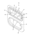
- FIG. 1 is a perspective view of the connector of the first embodiment.
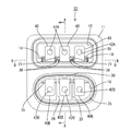
- FIG. 2 is a front view of the connector.
- 3 is a cross-sectional view taken along the line AA in FIG. 4 is a cross-sectional view taken along the line BB of FIG.
- FIG. 5 is a perspective view showing the first housing before connecting the second housing.
- FIG. 6 is a perspective view of the second housing.
- FIG. 7 is a perspective view showing a state in which the first housing and the second housing are connected.
- FIG. 8 is a perspective view showing a lid member attached to the back side of the connector.
- FIG. 9 is a perspective view of the connection member.
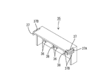
- FIG. 10 is a perspective view of the retainer.
- FIG. 11 is a front view of the retainer.
- FIG. 2 A connector 10 according to Embodiment 1 of the present invention will be described with reference to FIGS.
- the upper side of FIG. 2 is the upper side and the lower side is the lower side.
- the connector 10 of this embodiment is disposed on a vehicle body (not shown) such as an electric vehicle or a hybrid vehicle, and an inverter (an example of a first device) disposed on the vehicle body and a motor (of a second device). Electrical connection).
- the connector 10 includes a first housing 11 made of a synthetic resin having a first terminal portion connected to the inverter (terminal thereof) and a second terminal connected to the motor (terminal thereof). And a second housing 25 made of a synthetic resin having a portion in the vertical direction.
- the first housing 11 is provided with a substantially rectangular first opening 12 and an oval second opening 18.
- An inverter-side connector is attached to the first opening 12.
- a second housing 25 is provided in the second opening 18 via a connecting portion 30.
- a pair of ribs 16, 16 are formed on the outer surface of the first housing 11 along the opening edge of the first opening 12, and the pair of ribs 16, 16 is formed.
- a waterproof seal member 17 is attached to the first opening 12 to prevent water from entering.
- a protrusion 22 is formed on the outer surface of the first housing 11 so as to protrude outward along the opening edge of the second opening 18, and the connecting portion 30 is joined so as to sandwich the protrusion 22. Has been.
- the convex part 20 is formed (refer FIG. 3).
- a partition projection 21 that partitions the lower end surface 13 of the first opening 12 into three is formed on the convex portion 20 so as to reach the upper end surface 19 of the second opening 18.
- Three bus bars 40 are placed on the lower end surface 13 of the first opening 12 partitioned by the partition projection 21.
- the left and right end portions of the lower end surface 13 of the first opening 12 have a stepped shape, and the stepped portion 14 protrudes upward from the lower end surface 13 of the first opening 12.
- a locking claw 15 that locks a retainer 35 is provided on the end surface of this.
- the second housing 25 has a cylindrical shape and can be inserted into the hood portion of the mating connector (motor side connector).
- the second housing 25 has a shape along the second opening 18 and opens in an oval shape.
- the inside of the second housing 25 is partitioned into three regions by a partition wall 26, and the other end portion 40B of the bus bar 40 is disposed in each region (see FIGS. 2 and 6).
- a groove portion 27 is formed on the outer peripheral edge of the second housing 25, and a seal member 28 for preventing water from entering the second housing 25 is attached to the groove portion 27.
- a connecting protrusion 29 to which the connecting portion 30 is joined is formed to project from the end of the second housing 25 on the connecting portion 30 side.
- the bus bar 40 disposed from the first housing 11 to the second housing 25 is formed by pressing a plate made of a metal such as copper, copper alloy, stainless steel, or aluminum into a predetermined shape.
- the surface of the bus bar 40 may be plated with metal such as tin or nickel.
- the bus bar 40 has a shape that is bent in a substantially U shape, and is elastically deformable. Between one end 40A and the other end 40B of the bus bar 40, there are four bent portions (first bent portion 41A, second bent portion 41B, third bent portion 41C, fourth bent portion in order from the top in FIG. 41D) is formed.
- the bus bar 40 has a region between the first bent portion 41 ⁇ / b> A and the second bent portion 41 ⁇ / b> B placed on the lower end surface 13 (convex portion 20) of the first opening portion 12.
- a region between the second bent portion 41 ⁇ / b> B and the third bent portion 41 ⁇ / b> C is arranged in the vertical direction along the convex portion 20 in the first housing 11.
- the bus bar 40 bends (second bent portion 41B) substantially perpendicularly to the outer side direction (the left direction in the drawing) of the first housing 11 at the lower end surface 13 of the first opening portion 12, and then outwards from the first opening portion 12. And then bent vertically upward (first bent portion 41A).
- the bus bar 40 is slightly lower than the second opening 18 and is bent substantially perpendicularly to the outer side of the first housing 11 (third bent portion 41C), and then the joint portion 30 and the second housing 25 are joined. It is bent substantially vertically downward at a position corresponding to 30B (fourth bent portion 41D).
- Circular terminal connection holes 42 ⁇ / b> A and 42 ⁇ / b> B are formed in one end 40 ⁇ / b> A (the upper end in the drawing) and the other end 40 ⁇ / b> B (the lower end in the drawing) of the bus bar 40, respectively.
- the terminal connection hole 42A on the one end portion 40A side of the bus bar 40 is a first terminal portion 42A to which the connector terminal on the inverter side is connected.
- the terminal connection hole 42B on the other end 40B side of the bus bar 40 is a second terminal portion 42B to which the motor-side connector terminal is connected.
- the bus bar 40 placed on the lower end surface 13 of the first opening 12 of the first housing 11 is spaced from the convex portion 20 of the first housing 11 by a predetermined distance ( It is held with a gap of about 2 mm.
- the retainer 35 is attached so as to overlap the bus bar 40 placed on the lower end surface 13 of the first opening 12.
- Two pairs of ribs 36, 36 into which the partition projection 21 of the first opening 12 is fitted are provided on the inner surface of the upper surface of the retainer 35.
- a side surface disposed at a position facing the step portion 14 of the first opening 12 has a rectangular locking hole 37 ⁇ / b> A that receives and locks the locking claw 15 provided on the step portion 14. Is formed. Slits 37 ⁇ / b> B and 37 ⁇ / b> B that allow the locking portion 37 to bend and deform are formed on both sides of the locking portion 37 in which the locking hole 37 ⁇ / b> A of the retainer 35 is formed.
- a groove 38 into which the partition projection 21 can be fitted is formed on the side surface of the retainer 35 that is disposed on the lid member 31 side of the connector 10.
- the lid member 31 of the connector 10 has a shape in which a position corresponding to the convex portion 20 of the first housing 11 protrudes outward.
- a sealing member 32 is fitted along the outer peripheral edge of the lid member 31 to prevent water from entering the connector 10.
- a cylindrical connecting portion 30 is formed between the protrusion 22 of the second opening 18 of the first housing 11 and the connecting protrusion 29 of the second housing 25.
- the connecting part 30 is joined to the first housing 11 so as to sandwich the protrusion 22 of the second opening 18, and is joined to the second housing 25 so as to sandwich the connecting protrusion 29.
- the connecting portion 30 is made of a rubber material and is formed by two-color molding or insert molding.
- a known material such as a silicon rubber can be used as the material of the seal members 17, 28, and 32.
- the first housing 11 and the second housing 25 are joined and integrated to the connecting portion 30 (integration process, see FIGS. 5 to 7). Specifically, the material of the first housing 11 and the second housing 25 (synthetic resin material) and the material of the connecting portion 30 (silicon rubber) are poured into a predetermined mold and molded (two-color molding). The first housing 11 and the second housing 25 are joined and integrated with the connecting portion 30. Alternatively, any one of the first housing 11 and the second housing 25 and the connecting portion 30 is prepared, and the first housing 11 and the second housing 25 are joined and integrated by the connecting portion 30 by insert molding. To do.
- each component (bus bar 40, lid member 31, retainer 35) is produced.
- bending is performed to manufacture three pieces having a shape as shown in FIG.
- Seal members 17, 28, and 32 are attached to the ribs 16 and 16 at the opening edge of the first opening 12 of the first housing 11, the groove 27 of the second housing 25, and the lid member 31, respectively.
- the partition projection 21 is fitted between the ribs 36, 36 on the upper surface of the retainer 35, and the side surface of the retainer 35 is The partition projection 21 is fitted into the groove 38.
- the locking portion 37 of the retainer 35 bends inward when it comes into contact with the locking claw 15 of the first opening 12, but the locking claw 15 of the first opening 12 is disposed in the locking hole 37 ⁇ / b> A of the retainer 35. Then, the locking portion 37 is elastically restored, and the retainer 35 is locked.
- the bus bar 40 is held by the retainer 35 in a state where a predetermined interval is provided between the bus bar 40 and the convex portion 20 of the first housing 11.
- a rubber connecting portion 30 that connects the first housing 11 and the second housing 25 is a first device connected to the first terminal portion and a second device connected to the second terminal portion. As well as absorbing manufacturing tolerances and mounting tolerances, it also absorbs equipment vibrations. As a result, according to the present embodiment, it is possible to provide the connector 10 that can absorb the tolerance and vibration of the device.
- connection part 30 since the connection part 30 is integrated with the 1st housing 11 and the 2nd housing 25 by two-color molding or insert molding, the connection part 30 and each housing 11 and 25 are adhesive agents. It is joined more firmly than the case where it joins via, and the intensity
- the bus bar 40 having the first terminal portion at the one end portion 40A and the second terminal portion at the other end portion 40B is provided. Since connection is possible, a simple configuration can be achieved, and the manufacturing cost can be reduced.
- the bent portion that can be elastically deformed is provided between the one end portion 40A and the other end portion 40B of the bus bar 40, so that the bent portion of the bus bar 40 has two housings 11 and 25.
- the tolerance of the device can be absorbed by bending and deforming between them.
- the present invention is not limited to the embodiments described with reference to the above description and drawings.
- the following embodiments are also included in the technical scope of the present invention.
- the bus bar provided with the bent portion that is elastically deformable between the one end portion and the other end portion is shown. However, the bus bar does not have the elastically deformable bent portion. May be.
Landscapes
- Engineering & Computer Science (AREA)
- Manufacturing & Machinery (AREA)
- Mechanical Engineering (AREA)
- Connector Housings Or Holding Contact Members (AREA)
- Manufacturing Of Electrical Connectors (AREA)
Abstract
Description
そこで、特許文献1においては、モータとインバータとを一体化した構成が提案されている。
一端部に前記第1端子部を有するとともに、他端部に前記第2端子部を有する接続部材を備えていてもよい。このような構成とすると、1つの接続部材により2つの機器間の接続が可能となるので、簡易な構成とすることができ、製造コストを低減することができる。
本発明の実施形態1のコネクタ10を図1ないし図11によって説明する。以下の説明において、図2の上方を上とし、下方を下とする。
本実施形態のコネクタ10は、電気自動車やハイブリッド車等の車体(図示せず)に配設されて、この車体に配設されたインバータ(第1機器の一例)と、モータ(第2機器の一例)とを電気的に接続する。
第1ハウジング11および第2ハウジング25をそれぞれ連結部30に接合して一体化する(一体化工程、図5~図7を参照)。具体的には、第1ハウジング11及び第2ハウジング25の材料(合成樹脂材料)と連結部30の材料(シリコンゴム)とを、所定の金型に流し込んで成形し(二色成形)、第1ハウジング11および第2ハウジング25を連結部30に接合して一体化する。あるいは第1ハウジング11及び第2ハウジング25と連結部30のいずれか一方を作製しておいて、インサート成形により、第1ハウジング11と第2ハウジング25とをそれぞれ連結部30により接合して一体化する。
本実施形態においては、第1ハウジング11と第2ハウジング25とを連結するゴム製の連結部30が、第1端子部に接続された第1機器と第2端子部に接続された第2機器の製造公差や取付公差を吸収するとともに、機器の振動を吸収する。その結果、本実施形態によれば、機器の公差および振動を吸収できるコネクタ10を提供することができる。
本発明は上記記述及び図面によって説明した実施形態に限定されるものではなく、例えば次のような実施形態も本発明の技術的範囲に含まれる。
(1)上記実施形態では、一端部に第1端子部を有し、他端部に第2端子部を有するバスバーを備えるものを示したが、第1端子部のみを有するバスバーと第2端子部のみを有するバスバーと、これら2つのバスバーを接続する接続部材を備えるような構成としてもよい。
(2)上記実施形態では一端部と他端部との間に弾性変形可能な屈曲部を設けたバスバーを備えるものを示したが、バスバーは弾性変形可能な屈曲部を有さないものであってもよい。
(3)上記実施形態ではリテーナを備える構成を示したが、リテーナを備えないものであってもよい。
11...第1ハウジング
25...第2ハウジング
30...連結部
30A...(第1ハウジングと連結部との)接合部
30B...(第2ハウジングと連結部との)接合部
40...バスバー(接続部材)
40A...一端部
40B...他端部
41A...第1屈曲部
41B...第2屈曲部
41C...第3屈曲部
41D...第4屈曲部
42A...一端部側の端子接続孔(第1端子部)
42B...他端部側の端子接続孔(第2端子部)
Claims (6)
- 第1機器に接続される第1端子部を有する樹脂製の第1ハウジングと、第2機器に接続される第2端子部を有する樹脂製の第2ハウジングと、を備えるコネクタであって、
前記第1ハウジングおよび前記第2ハウジングを、インサート成形または二色成形により形成されたゴム製の連結部により連結し一体化したことを特徴とするコネクタ。 - 一端部に前記第1端子部を有するとともに、他端部に前記第2端子部を有する接続部材を備えることを特徴とする請求項1に記載のコネクタ。
- 前記接続部材の前記一端部と前記他端部との間に、弾性変形可能な屈曲部を設けたことを特徴とする請求項2に記載のコネクタ。
- 第1機器に接続される第1端子部を有する樹脂製の第1ハウジングと、第2機器に接続される第2端子部を有する樹脂製の第2ハウジングと、を備えるコネクタの製造方法であって、
前記第1ハウジングおよび前記第2ハウジングを、インサート成形または二色成形により、ゴム製の連結部で連結し一体化する一体化工程を含むことを特徴とするコネクタの製造方法。 - 一端部に前記第1端子部を有するとともに、他端部に前記第2端子部を有する接続部材を備えることを特徴とする請求項4に記載のコネクタの製造方法。
- 前記接続部材の前記一端部と前記他端部との間に、弾性変形可能な屈曲部を設けたことを特徴とする請求項5に記載のコネクタの製造方法。
Priority Applications (3)
| Application Number | Priority Date | Filing Date | Title |
|---|---|---|---|
| CN201280021515.9A CN103518294B (zh) | 2011-06-02 | 2012-04-13 | 连接器及其制造方法 |
| DE112012002287.4T DE112012002287B4 (de) | 2011-06-02 | 2012-04-13 | Verbinder und Verfahren zum Herstellen desselben |
| US14/123,334 US9209555B2 (en) | 2011-06-02 | 2012-04-13 | Connector and method for manufacturing same |
Applications Claiming Priority (2)
| Application Number | Priority Date | Filing Date | Title |
|---|---|---|---|
| JP2011124091A JP5672157B2 (ja) | 2011-06-02 | 2011-06-02 | コネクタおよびその製造方法 |
| JP2011-124091 | 2011-06-02 |
Publications (1)
| Publication Number | Publication Date |
|---|---|
| WO2012165063A1 true WO2012165063A1 (ja) | 2012-12-06 |
Family
ID=47258927
Family Applications (1)
| Application Number | Title | Priority Date | Filing Date |
|---|---|---|---|
| PCT/JP2012/060122 Ceased WO2012165063A1 (ja) | 2011-06-02 | 2012-04-13 | コネクタおよびその製造方法 |
Country Status (5)
| Country | Link |
|---|---|
| US (1) | US9209555B2 (ja) |
| JP (1) | JP5672157B2 (ja) |
| CN (1) | CN103518294B (ja) |
| DE (1) | DE112012002287B4 (ja) |
| WO (1) | WO2012165063A1 (ja) |
Families Citing this family (4)
| Publication number | Priority date | Publication date | Assignee | Title |
|---|---|---|---|---|
| DE102014116838A1 (de) * | 2014-11-18 | 2016-05-19 | Ebm-Papst Mulfingen Gmbh & Co. Kg | Elektrische Verbindungsanordnung und Verfahren zu deren Herstellung |
| US9994166B2 (en) * | 2015-08-19 | 2018-06-12 | Ford Global Technologies, Llc | Dual molded grab handle spacer for a motor vehicle |
| JP7139930B2 (ja) | 2018-12-14 | 2022-09-21 | 株式会社オートネットワーク技術研究所 | 端子台と機器内固定部との固定構造 |
| CN113366739B (zh) * | 2019-02-08 | 2024-03-08 | Gkn汽车有限公司 | 连接器组件、驱动单元以及电连接方法 |
Citations (4)
| Publication number | Priority date | Publication date | Assignee | Title |
|---|---|---|---|---|
| JP2004215355A (ja) * | 2002-12-27 | 2004-07-29 | Aisin Aw Co Ltd | 電動駆動装置制御ユニットの防振装置 |
| JP2008146988A (ja) * | 2006-12-08 | 2008-06-26 | Hitachi Cable Ltd | コネクタ構造 |
| JP2010080106A (ja) * | 2008-09-24 | 2010-04-08 | Sumitomo Wiring Syst Ltd | コネクタ |
| WO2011016272A1 (ja) * | 2009-08-03 | 2011-02-10 | 矢崎総業株式会社 | コネクタ |
Family Cites Families (16)
| Publication number | Priority date | Publication date | Assignee | Title |
|---|---|---|---|---|
| JPS63221568A (ja) * | 1987-03-10 | 1988-09-14 | 矢崎総業株式会社 | コネクタ用ハウジング及びその製造法 |
| JPH04112482U (ja) * | 1991-03-20 | 1992-09-30 | 株式会社日立製作所 | 緩衝コネクタ |
| JP3056356B2 (ja) * | 1993-08-31 | 2000-06-26 | 三菱電機株式会社 | 自動車用センサ |
| US7104840B2 (en) * | 2003-06-27 | 2006-09-12 | Yazaki Corporation | Electrical connector |
| CN2800520Y (zh) * | 2005-04-28 | 2006-07-26 | 富士康(昆山)电脑接插件有限公司 | 电连接器 |
| JP4537966B2 (ja) * | 2006-02-20 | 2010-09-08 | 矢崎総業株式会社 | 防水コネクタ |
| JP2007335328A (ja) * | 2006-06-16 | 2007-12-27 | Sumitomo Wiring Syst Ltd | 嵌合部材 |
| US7717747B2 (en) * | 2006-11-06 | 2010-05-18 | Gm Global Technology Operations, Inc. | Power inverter connector having integrated current sensors |
| US20090023305A1 (en) * | 2007-07-17 | 2009-01-22 | Gm Global Technology Operations, Inc. | Multiple use electric current connector assembly for vehicles |
| US7581991B2 (en) * | 2007-07-17 | 2009-09-01 | Gm Global Technology Operations, Inc. | Vehicle electric current connector assembly with electric current sensors |
| WO2010095697A1 (ja) * | 2009-02-20 | 2010-08-26 | 矢崎総業株式会社 | 防水コネクタ |
| JP5271747B2 (ja) * | 2009-02-20 | 2013-08-21 | 矢崎総業株式会社 | 防水コネクタ |
| JP2011062023A (ja) * | 2009-09-11 | 2011-03-24 | Aisin Aw Co Ltd | 電気的接続装置 |
| US8672700B2 (en) * | 2009-12-10 | 2014-03-18 | Yazaki Corporation | Connector assembly |
| JP5626047B2 (ja) * | 2011-03-15 | 2014-11-19 | 住友電装株式会社 | 機器用コネクタ |
| JP5751875B2 (ja) * | 2011-03-22 | 2015-07-22 | 矢崎総業株式会社 | シールドコネクタ |
-
2011
- 2011-06-02 JP JP2011124091A patent/JP5672157B2/ja not_active Expired - Fee Related
-
2012
- 2012-04-13 DE DE112012002287.4T patent/DE112012002287B4/de not_active Expired - Fee Related
- 2012-04-13 US US14/123,334 patent/US9209555B2/en not_active Expired - Fee Related
- 2012-04-13 CN CN201280021515.9A patent/CN103518294B/zh not_active Expired - Fee Related
- 2012-04-13 WO PCT/JP2012/060122 patent/WO2012165063A1/ja not_active Ceased
Patent Citations (4)
| Publication number | Priority date | Publication date | Assignee | Title |
|---|---|---|---|---|
| JP2004215355A (ja) * | 2002-12-27 | 2004-07-29 | Aisin Aw Co Ltd | 電動駆動装置制御ユニットの防振装置 |
| JP2008146988A (ja) * | 2006-12-08 | 2008-06-26 | Hitachi Cable Ltd | コネクタ構造 |
| JP2010080106A (ja) * | 2008-09-24 | 2010-04-08 | Sumitomo Wiring Syst Ltd | コネクタ |
| WO2011016272A1 (ja) * | 2009-08-03 | 2011-02-10 | 矢崎総業株式会社 | コネクタ |
Also Published As
| Publication number | Publication date |
|---|---|
| DE112012002287B4 (de) | 2017-10-19 |
| CN103518294A (zh) | 2014-01-15 |
| DE112012002287T5 (de) | 2014-03-13 |
| JP5672157B2 (ja) | 2015-02-18 |
| JP2012252861A (ja) | 2012-12-20 |
| US9209555B2 (en) | 2015-12-08 |
| US20140140763A1 (en) | 2014-05-22 |
| CN103518294B (zh) | 2016-03-09 |
Similar Documents
| Publication | Publication Date | Title |
|---|---|---|
| JP6164571B2 (ja) | 電気接続箱 | |
| CN102916376B (zh) | 防水盒以及具有该防水盒的电接线盒 | |
| JP5423655B2 (ja) | 電力変換装置 | |
| CN102738670B (zh) | 设备连接器及其制造方法 | |
| JP5991260B2 (ja) | コネクタ及びワイヤハーネス | |
| JP5995105B2 (ja) | コネクタ | |
| JP2014086349A (ja) | コネクタ | |
| JP5672157B2 (ja) | コネクタおよびその製造方法 | |
| JP5682784B2 (ja) | 電気接続箱 | |
| CN107776674A (zh) | 电气装置安装结构 | |
| CN113454852A (zh) | 端子座 | |
| US8747137B2 (en) | Connector | |
| JP2014232686A (ja) | 端子台 | |
| JP2014082080A (ja) | 位置ずれ吸収部材及びバスバーユニット | |
| JP7328036B2 (ja) | モータ装置およびその組立方法 | |
| JP2011044407A (ja) | コネクタ | |
| JP5370862B2 (ja) | コネクタ | |
| JP6141807B2 (ja) | 車両搭載用筐体 | |
| JP6520425B2 (ja) | 機器用弾性シールド部材 | |
| JP2017143024A (ja) | 機器用コネクタ | |
| JP5828317B2 (ja) | 電気接続箱 | |
| JP2011250569A (ja) | 電気接続箱 | |
| JP6477241B2 (ja) | 機電一体型モータ装置 | |
| JP7115938B2 (ja) | 電気接続箱及びワイヤハーネス | |
| JP2009016100A (ja) | ハーネスコネクタの防水カバーとそれを用いたハーネスコネクタ |
Legal Events
| Date | Code | Title | Description |
|---|---|---|---|
| WWE | Wipo information: entry into national phase |
Ref document number: 201280021515.9 Country of ref document: CN |
|
| 121 | Ep: the epo has been informed by wipo that ep was designated in this application |
Ref document number: 12792404 Country of ref document: EP Kind code of ref document: A1 |
|
| WWE | Wipo information: entry into national phase |
Ref document number: 1120120022874 Country of ref document: DE Ref document number: 112012002287 Country of ref document: DE |
|
| WWE | Wipo information: entry into national phase |
Ref document number: 14123334 Country of ref document: US |
|
| 122 | Ep: pct application non-entry in european phase |
Ref document number: 12792404 Country of ref document: EP Kind code of ref document: A1 |