WO2012161182A1 - インプラント用キーパー及びその組立体、並びにキーパーの固定方法 - Google Patents
インプラント用キーパー及びその組立体、並びにキーパーの固定方法 Download PDFInfo
- Publication number
- WO2012161182A1 WO2012161182A1 PCT/JP2012/063022 JP2012063022W WO2012161182A1 WO 2012161182 A1 WO2012161182 A1 WO 2012161182A1 JP 2012063022 W JP2012063022 W JP 2012063022W WO 2012161182 A1 WO2012161182 A1 WO 2012161182A1
- Authority
- WO
- WIPO (PCT)
- Prior art keywords
- keeper
- abutment
- implant
- screw member
- diameter
- Prior art date
- Legal status (The legal status is an assumption and is not a legal conclusion. Google has not performed a legal analysis and makes no representation as to the accuracy of the status listed.)
- Ceased
Links
Images






Classifications
-
- A—HUMAN NECESSITIES
- A61—MEDICAL OR VETERINARY SCIENCE; HYGIENE
- A61C—DENTISTRY; APPARATUS OR METHODS FOR ORAL OR DENTAL HYGIENE
- A61C8/00—Means to be fixed to the jaw-bone for consolidating natural teeth or for fixing dental prostheses thereon; Dental implants; Implanting tools
- A61C8/0081—Magnetic dental implant retention systems
-
- A—HUMAN NECESSITIES
- A61—MEDICAL OR VETERINARY SCIENCE; HYGIENE
- A61C—DENTISTRY; APPARATUS OR METHODS FOR ORAL OR DENTAL HYGIENE
- A61C8/00—Means to be fixed to the jaw-bone for consolidating natural teeth or for fixing dental prostheses thereon; Dental implants; Implanting tools
- A61C8/0048—Connecting the upper structure to the implant, e.g. bridging bars
- A61C8/005—Connecting devices for joining an upper structure with an implant member, e.g. spacers
-
- A—HUMAN NECESSITIES
- A61—MEDICAL OR VETERINARY SCIENCE; HYGIENE
- A61C—DENTISTRY; APPARATUS OR METHODS FOR ORAL OR DENTAL HYGIENE
- A61C13/00—Dental prostheses; Making same
- A61C13/225—Fastening prostheses in the mouth
- A61C13/235—Magnetic fastening
-
- A—HUMAN NECESSITIES
- A61—MEDICAL OR VETERINARY SCIENCE; HYGIENE
- A61C—DENTISTRY; APPARATUS OR METHODS FOR ORAL OR DENTAL HYGIENE
- A61C19/00—Dental auxiliary appliances
- A61C19/02—Protective casings, e.g. boxes for instruments; Bags
-
- A—HUMAN NECESSITIES
- A61—MEDICAL OR VETERINARY SCIENCE; HYGIENE
- A61C—DENTISTRY; APPARATUS OR METHODS FOR ORAL OR DENTAL HYGIENE
- A61C8/00—Means to be fixed to the jaw-bone for consolidating natural teeth or for fixing dental prostheses thereon; Dental implants; Implanting tools
- A61C8/0048—Connecting the upper structure to the implant, e.g. bridging bars
- A61C8/005—Connecting devices for joining an upper structure with an implant member, e.g. spacers
- A61C8/0059—Connecting devices for joining an upper structure with an implant member, e.g. spacers with additional friction enhancing means
-
- A—HUMAN NECESSITIES
- A61—MEDICAL OR VETERINARY SCIENCE; HYGIENE
- A61C—DENTISTRY; APPARATUS OR METHODS FOR ORAL OR DENTAL HYGIENE
- A61C8/00—Means to be fixed to the jaw-bone for consolidating natural teeth or for fixing dental prostheses thereon; Dental implants; Implanting tools
- A61C8/0048—Connecting the upper structure to the implant, e.g. bridging bars
- A61C8/005—Connecting devices for joining an upper structure with an implant member, e.g. spacers
- A61C8/0068—Connecting devices for joining an upper structure with an implant member, e.g. spacers with an additional screw
-
- A—HUMAN NECESSITIES
- A61—MEDICAL OR VETERINARY SCIENCE; HYGIENE
- A61C—DENTISTRY; APPARATUS OR METHODS FOR ORAL OR DENTAL HYGIENE
- A61C8/00—Means to be fixed to the jaw-bone for consolidating natural teeth or for fixing dental prostheses thereon; Dental implants; Implanting tools
- A61C8/0048—Connecting the upper structure to the implant, e.g. bridging bars
- A61C8/005—Connecting devices for joining an upper structure with an implant member, e.g. spacers
- A61C8/0069—Connecting devices for joining an upper structure with an implant member, e.g. spacers tapered or conical connection
-
- A—HUMAN NECESSITIES
- A61—MEDICAL OR VETERINARY SCIENCE; HYGIENE
- A61C—DENTISTRY; APPARATUS OR METHODS FOR ORAL OR DENTAL HYGIENE
- A61C8/00—Means to be fixed to the jaw-bone for consolidating natural teeth or for fixing dental prostheses thereon; Dental implants; Implanting tools
- A61C8/0048—Connecting the upper structure to the implant, e.g. bridging bars
- A61C8/005—Connecting devices for joining an upper structure with an implant member, e.g. spacers
- A61C8/0074—Connecting devices for joining an upper structure with an implant member, e.g. spacers with external threads
Definitions
- the present invention relates to an implant keeper for fixing a denture magnetic attachment to an implant body, an assembly thereof, and a keeper fixing method.
- US Pat. No. 6,709,270 discloses a magnetic dental attachment in which a denture attachment 105 containing a magnet 155 is magnetically attached to a keeper 103 made of a soft magnetic material screwed into an implant body 110, as shown in FIG. is doing.
- the keeper 103 includes a conical tapered portion 135 provided at the upper portion, and a ring portion 137 that protrudes from the outer peripheral surface at the upper end of the conical tapered portion 135 and has an annular groove on the back side.
- the implant body 110 has a conical tapered recess 115 complementary to the tapered portion 135 of the keeper 103.
- JP 2009-131620 as shown in FIG. 16, (a) heel implant body 205, (b) a head 241 having a heel female threaded portion 243, and abutment 204 screwed into the implant body 205, (c) a keeper main body 202 made of a soft magnetic material having a recess 221 for receiving the head 241 of the heel abutment 204, and a female screw portion 222 provided along the central axis so as to communicate with the recess 221; ) It consists of a female screw portion 222 of the keeper main body 202 and a screw member 203 screwed to the female screw portion 243 of the abutment 204.
- the screw member 203 An implant keeper assembly is disclosed in which a female screw portion 222 of a keeper body 202 and a female screw portion 243 of an abutment 204 are screwed together.
- the screw member 203 does not have a portion that contacts the keeper main body 202 or the abutment 204, it is necessary to manually adjust the axial position of the screw member 203 screwed to the keeper main body 202 and the abutment 204.
- the thread of the female thread portion 222 of the keeper body 202 is the minimum number necessary for screwing with the screw member 203 (about 3 to 4 pieces) Only. Therefore, when the screwing position of the screw member 203 is shifted to the abutment 204 side, the coupling strength between the keeper main body 202 and the screw member 203 becomes insufficient, and when the screw member 203 is shifted to the opposite side, the head of the screw member 203 is moved to the keeper main body 202. Therefore, the screw member 203 must be accurately positioned by hand.
- an object of the present invention is to provide an implant keeper that can be accurately and easily screwed to an abutment and that does not loosen even after long-term use.
- Another object of the present invention is to provide a method for fixing the keeper for an implant to an abutment.
- Still another object of the present invention is to provide an implant keeper assembly comprising a keeper main body, an abutment, and a screw member for screwing them together.
- the keeper for an implant of the present invention is provided with (a) a recess for receiving the head of an abutment having a female threaded portion and a central axis so as to communicate with the recessed portion, and is larger than the female threaded portion of the abutment.
- the method for fixing the implant keeper to the abutment includes screwing the small-diameter screw portion of the two-stage screw member into the female screw portion of the abutment and the two-stage screw to the female screw portion of the keeper body. After the large-diameter screw portion of the member is screwed, the keeper main body is rotated in the screwing direction, and the keeper main body is firmly fastened to the abutment by the two-stage screw member.
- the two-stage screw member has a stepped portion or a tapered portion between the small-diameter screw portion and the large-diameter screw portion, and the two-stage screw member until the stepped portion or the tapered portion engages with the upper end surface of the abutment.
- the stepped screw member is screwed into the female threaded portion of the abutment, it is preferable that the two-stage screw member can be accurately positioned in the axial direction.
- An implant keeper assembly of the present invention to be fixed to an implant body embedded in a jawbone includes: (a) a heel head, a female screw portion provided along a central axis of the head, and a lower portion of the head.
- An abutment having a male screw portion screwed into the implant body, (b) a recess for receiving the head of the abutment, provided along the central axis so as to communicate with the recess,
- a keeper body made of a soft magnetic material having a female thread portion having a larger nominal diameter than the female thread portion of the abutment; (c) a small-diameter screw portion screwed into the female thread portion of the abutment; and a female thread portion of the keeper body
- a two-stage screw member having a large-diameter screw portion to be screwed, and the small-diameter screw portion of the two-stage screw member is screwed into the female screw portion of the abutment, and the keeper After
- the two-stage screw member has a stepped portion or a tapered portion between the small-diameter screw portion and the large-diameter screw portion, and the stepped portion or the tapered portion is the abutment. It is preferable that the two-stage screw member can be accurately positioned in the axial direction when the two-stage screw member is screwed into the female thread portion of the abutment until the upper end surface of the abutment is engaged.
- At least a part of the head of the abutment has a truncated cone shape, and the inner surface of the concave portion of the keeper body has a conical shape complementary to the truncated cone portion of the abutment head, thereby It is preferable that the frustoconical portion of the abutment head is in close contact with the inner surface of the concave portion of the keeper body when fastened to the abutment.
- the side surface portion of the keeper main body has a nut shape, and the keeper main body is rotated in the screwing direction using a tool that engages with the nut-shaped side surface portion.
- the abutment has a flange portion extending radially outward from a lower end of the head, an upper surface outer peripheral portion of the flange portion abuts an outer edge portion of the keeper body, and a lower surface of the flange portion is the implant. It is preferable to contact the upper end surface of the main body.
- the head of the abutment is inclined with respect to the central axis of the implant body, and the abutment is inserted into a central hole of the implant body, and the side surface of the head from the cylindrical portion. It is preferable that the abutment is fixed to the implant body by screwing a screw member penetrating the through hole and the cylindrical portion into the female screw portion of the implant body.
- the large-diameter screw portion screwed into the female screw portion of the keeper body made of a soft magnetic material and the female screw portion of the abutment are screwed together.
- a tension is applied in the opposite direction to the small-diameter screw portion, and the keeper main body and the abutment are firmly fastened by a two-stage screw member, so that they do not loosen even when used for a long time.
- the two-stage screw member has a stepped portion or a tapered portion between the small-diameter screw portion and the large-diameter screw portion, when the two-stage screw member is screwed to the female screw portion of the abutment, the stepped portion or the tapered portion is formed. By engaging with the upper end surface of the abutment, the two-stage screw member can be accurately and easily positioned in the axial direction (displacement of the screwing position can be prevented).
- the implant keeper according to the present invention has a small number of parts and can be easily attached to the abutment, so that the dental implant can be treated in a short time.
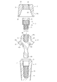
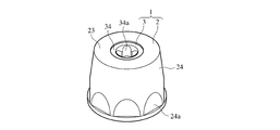
- FIG. 2 is a partial cross-sectional view showing the implant keeper assembly of FIG. It is a perspective view which shows the keeper for implants by 1st embodiment of this invention.
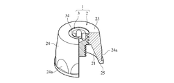
- FIG. 4 is a partial cross-sectional perspective view showing the implant keeper of FIG. It is sectional drawing which shows the keeper main body used for 1st embodiment of this invention.
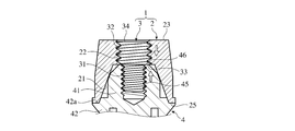
- FIG. 4 is a partial sectional view showing a state in which the implant keeper of FIG. 3 is screwed to an abutment.
- FIG. 2 is a partial cross-sectional view showing a state where a magnetic attachment is attracted to the implant keeper assembly of FIG.
- FIG. 9 is a partial cross-sectional view showing the implant keeper assembly of FIG. It is an expanded partial sectional view which shows the state which fixed the keeper for implants by 2nd embodiment of this invention to the abutment. It is a top view which shows the two-stage screw member used for 2nd embodiment of this invention.
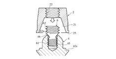
- FIG. 11 (a) is a partial cross-sectional view showing a two-stage screw member of FIG. It is a fragmentary sectional view which shows the state just before screwing a two-stage type screw member to an abutment in order to screw the keeper for implants by 2nd embodiment of this invention to an abutment.
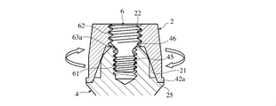
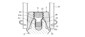
- FIG. 14 is a partial cross-sectional view showing the implant keeper assembly of FIG.
- FIG. 6 is an exploded cross-sectional view showing a magnetic dental attachment described in US Pat. No. 6,709,270.
- 1 is a cross-sectional view showing an implant keeper assembly described in JP-A-2009-131620.
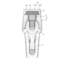
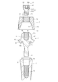
- FIGS. 1 and 2 show an implant keeper and its assembly according to a first embodiment of the present invention.
- the implant keeper assembly fixed to the implant body 5 includes an abutment 4 screwed into the implant body 5 and a keeper 1.
- the keeper 1 includes a keeper body 2 having a screw hole 22, and a keeper body 2.
- the two-stage screw member 3 screwed into the screw hole 45 of the head 41 of the abutment 4.
- the implant body 5 is a cylindrical member having a male threaded portion 53 on the outer peripheral surface for embedding in the jawbone, a central hole 51 for inserting the lower male threaded portion 43 of the abutment 4, and the back side of the central hole 51 A female screw portion 52 that is screwed with the male screw portion 43, and an annular convex portion 54 that protrudes concentrically with the central hole portion 51 from the upper end surface.
- the implant body 5 preferably has an outer diameter (about 3 to 6.5 mm) and a length (about 10 mm) according to normal implant treatment.
- the implant body 5 is preferably made of pure titanium or a titanium alloy from the viewpoint of biocompatibility with the jawbone, corrosion resistance, and mechanical strength. In order to improve biocompatibility, surface treatment with hydroxyapatite may be performed.
- the abutment 4 is screwed to a head 41 that engages with the tapered recess 21 of the keeper 1, a flange 42 that extends radially outward from the lower end of the head 41, and a female thread 52 of the implant body 5. And a lower male screw portion 43.
- the flange portion 42 has two upper surfaces, and the bottom edge portion 25 of the keeper main body 2 abuts on the outer lower upper surface portion 42a. Further, the lower surface 42b of the flange portion 42 is in contact with the upper end surface of the implant body 5, and the annular recess 42c with which the annular projection 54 of the implant body 5 is engaged is provided on the lower surface 42b.
- the head portion 41 of the abutment 4 has a female thread portion 45 that opens to the center of the upper end surface, and a nut-shaped side surface portion 47, and a part of the side surface portion 47 engages with the tapered recess 21 of the keeper 1. 47a.
- the abutment 4 is preferably made of the same material as the implant body 5.
- the truncated cone-shaped keeper main body 2 has a tapered recess 21 for receiving the head 41 of the abutment 4 and a center of the upper surface 23 so as to communicate with the tapered recess 21. And an internal thread 22 that opens.
- the female threaded portion 22 of the keeper body 2 has a larger nominal diameter than the female threaded portion 45 of the abutment 4.
- the keeper main body 2 (height t1) has a truncated cone shape (D1 ⁇ D2), and a part of the conical side surface 24 is an octagonal nut portion 24a having a height t3 that is about 1/2 of t1, for example.
- the octagonal nut shape is an example, and the hexagonal nut shape in which the interval between the opposing surfaces conforms to JIS B 1181 may be used.
- the size of the upper surface 23 of the keeper body 2 is appropriately set according to the size of the magnetic denture attachment 9 (see FIG. 7). Since the tapered concave portion 21 of the keeper body 2 is complementary to the tapered surface portion 47a of the head 41 of the abutment 4, the tapered concave portion 21 is closely engaged with the tapered surface portion 47a.
- a small-diameter screw portion 31 screwed into the female screw portion 45 of the abutment 4 and a large-diameter screw portion 32 screwed into the female screw portion 22 of the keeper main body 2 are connected coaxially and integrally.
- a stepped portion 33 is provided between the small-diameter screw portion 31 and the large-diameter screw portion 32.
- the nominal diameter d1 of the small diameter screw portion 31 of the two-stage screw member 3 is preferably about 1.2 to 1.8 mm, and the nominal diameter d2 of the large diameter screw portion 32 is preferably about 1.6 to 3.0 mm.
- the nominal diameter d1 of the small diameter screw portion 31 needs to be at least about 1.2 mm in order to function as a screw. Further, if the nominal diameter d2 of the large-diameter screw portion 32 is more than 3.0 mm, the area of the upper surface 23 of the keeper body 2 is reduced, and the attractive force to the magnetic denture attachment is weak.
- the stepped portion 33 of the two-stage screw member 3 needs to be large enough to be locked to the upper end surface when the two-stage screw member 3 is screwed to the abutment 4.
- the ratio d2 / d1 between the nominal diameter d2 of the large-diameter screw portion 32 and the nominal diameter d1 of the small-diameter screw portion 31 is preferably about 1.2 to 1.5.
- Keeper body 2 must be formed of a soft magnetic material so as to be magnetically attracted to the magnetic denture attachment, and is preferably a ferritic stainless steel (see JIS G-3430) having excellent soft magnetism and corrosion resistance.
- the two-stage screw member 3 is also preferably made of a soft magnetic material like the keeper body 2 so that it can be magnetically attracted to the magnetic denture attachment, but it is made of a nonmagnetic material such as titanium because it is small. Also good.
- the keeper main body 2 is placed on the abutment 4, and the large-diameter screw portion 32 of the two-stage screw member 3 is screwed into the female screw portion 22 of the keeper main body 2.
- the keeper body 2 is rotated in the screwing direction.
- the keeper main body 2 In the state where the keeper main body 2 and the abutment 4 are in contact with each other, the keeper main body 2 is rotated in the screwing direction (usually in the direction of the right screw) with a predetermined wrench, and the keeper main body 2 is firmly fastened to the abutment 4. At this time, the upper end surface 34 of the two-stage screw member 3 is prevented from protruding from the upper surface 23 of the keeper body 2. That is, the upper end surface 34 of the two-stage screw member 3 is substantially flush with or slightly lower than the upper surface 23 of the keeper body 2.
- the large-diameter screw portion 32 of the two-stage screw member 3 is the same as or slightly the same as the female screw portion 22 of the keeper body 2.
- the positioning of the upper end surface 34 of the two-stage screw member 3 can be performed accurately and easily.
- the stepped portion 33 of the two-stage screw member 3 is locked to the upper end surface 46 of the abutment 4, so that the screwing position of the keeper body 2 to the two-stage screw member 3 is not shifted.
- the lower part of the thread of the large-diameter screw portion 32 of the two-stage screw member 3 is screwed into the two-stage screw member 3 of the keeper body 2 so that the female screw portion of the keeper body 2
- the upper part of the screw thread 22 is pressed, and the upper part of the screw thread of the small diameter screw part 31 of the two-stage screw member 3 presses the lower part of the screw thread of the female screw part 45 of the abutment 4. That is, the keeper body 2 is pressed downward by the two-stage screw member 3, and the abutment 4 is pressed upward. Therefore, the keeper main body 2 is firmly fastened to the abutment 4 and does not loosen even when a repeated load is applied.
- a magnetic attachment 9 shown in FIG. 7 includes a cup-shaped yoke 91 made of a soft magnetic material having a recess having a circular cross section, a disk-shaped permanent magnet 92 housed in the recess and magnetized in the thickness direction, and the recess. It consists of a sealing plate 93 for sealing.
- the seal plate 93 is a member that seals the permanent magnet 92 in the recess and serves as a magnetic path.
- the soft magnetic material is preferably a corrosion resistant metal such as ferritic stainless steel (for example, SUS447J1), and the nonmagnetic material is preferably a corrosion resistant metal such as austenitic stainless steel (for example, SUS316L).
- ferritic stainless steel for example, SUS447J1
- austenitic stainless steel for example, SUS316L
- an R-T-B system sintered magnet having high magnetic properties for example, an Nd-Fe-B system anisotropic sintered magnet
- This sintered magnet has 27 to 34% by mass of R (at least one of rare earth elements including Y, and at least one of Nd, Dy, and Pr), 0.6 to 1.8% by mass of B, and the balance substantially In particular, it preferably has a composition consisting of T (Fe or Co).
- R is less than 27% by mass, the coercive force (iHc) is too low, and when it exceeds 34% by mass, the residual magnetic flux density Br is significantly reduced.
- composition of the RTB sintered magnet is 27 to 32 mass% R, 0.6 to 1.8 mass% B, 0.0001 to 20 mass% Co, 0.001 to 3 mass% M (Al, Si, Cu, Ga) At least one selected from the group consisting of Nb, Mo and W), and the balance substantially consisting of Fe.
- FIGS. 8 to 10 show an implant keeper and its assembly according to a second embodiment of the present invention.
- the second embodiment is basically the same as the first embodiment except that a two-stage screw member 6 shown in FIG. 11 is used as the screw member of the keeper body 2.
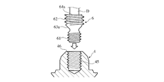
- the two-stage screw member 6 includes a small-diameter screw portion 61 (length L 1 ) screwed into the female screw portion 45 of the abutment 4 along the central axis in order from the bottom, and a non-threaded small-diameter portion 63 (length). L 3 ) and a large-diameter screw portion 62 (length L 2 ) that is screwed into the female screw portion 22 of the keeper body 2 are integrally provided.
- the small diameter portion 63 includes a first taper portion 63a that decreases in diameter from the large diameter screw portion 62 toward the small diameter screw portion 61, and a second taper portion 63b that decreases in diameter from the small diameter screw portion 61 toward the large diameter screw portion 62.
- the upper end surface 64 of the two-stage screw member 6 is provided with a clover hole 64a for screwing in the driver.
- a clover hole 64a for screwing in the driver.
- a slot specified in JIS B 1117 or a hexagon hole specified in JIS B 1177 may be used.
- the nominal diameters of the small-diameter screw portion 61 and the large-diameter screw portion 62 of the two-stage screw member 6 may be the same as those of the two-stage screw member 3.
- the upper part of the thread of the small-diameter screw part 61 of the two-stage screw member 6 presses the lower part of the thread of the female thread part 45 of the abutment 4,
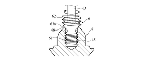
- the screw member 6 is locked to the abutment 4. If the length of the female screw portion 22 of the keeper main body 2 and the length of the large-diameter screw portion 62 of the two-stage screw member 6 are set in advance, the abutment 4 of the first taper portion 63a of the two-stage screw member 6 is set. By contacting the upper end surface 46, the upper end surface 64 of the two-stage screw member 6 can be accurately and easily positioned.
- the two-stage screw member 6 is locked to the abutment 4 by the contact of the first tapered portion 63a of the two-stage screw member 6 with the upper end surface 46 of the abutment 4, the screwing of the keeper body 2 is prevented. At this time, the screwing position of the two-stage screw member 6 does not shift. Therefore, the first taper portion 63a can be called a locking portion.
- the keeper main body 2 is put on the abutment 4, and the female screw portion 22 of the keeper main body 2 is screwed with the large-diameter screw portion 62 of the two-stage screw member 6.
- the keeper body 2 until the bottom edge 25 of the keeper body 2 abuts against the flange portion 42 of the abutment 4 or the tapered recess 21 of the keeper body 2 abuts the upper end surface 46 of the head 41 of the abutment 4 Is rotated in the screwing direction.
- FIG. 12 (d) the keeper main body 2 is put on the abutment 4, and the female screw portion 22 of the keeper main body 2 is screwed with the large-diameter screw portion 62 of the two-stage screw member 6.
- the keeper body 2 is rotated in the screwing direction with a wrench 16 set to a predetermined torque (for example, 20 to 30 N ⁇ cm), and the keeper body 2 is moved by the two-stage screw member 6. Tighten firmly to the abutment 4.
- a wrench 16 set to a predetermined torque (for example, 20 to 30 N ⁇ cm)
- the keeper body 2 is moved by the two-stage screw member 6. Tighten firmly to the abutment 4.
- the female screw portion 22 of the keeper main body 2 and the large-diameter screw portion 62 of the two-stage screw member 6 are set to a predetermined length. It does not protrude from the upper surface 23 (substantially flush with or slightly lower than the upper surface 23 of the keeper body 2).
- the lower part of the thread of the large diameter thread part 62 of the two-stage screw member 6 is above the thread of the female thread part 22 of the keeper body 2.
- the upper part of the thread of the small diameter thread part 61 of the two-stage screw member 6 presses the lower part of the thread of the female thread part 45 of the abutment 4. That is, the keeper body 2 is pressed downward by the two-stage screw member 6, and the abutment 4 is pressed upward. Therefore, the keeper main body 2 is firmly fastened to the abutment 4 and does not loosen even when a repeated load is applied.
- the two-stage screw member 6 when the two-stage screw member 6 is screwed to the female thread portion 45 of the abutment 4 until the first tapered portion 63a of the two-stage screw member 6 contacts the upper end surface 46 of the abutment 4, The two-stage screw member 6 engages with the abutment 4 in a state where the upper part of the thread of the small diameter screw part 61 of the screw member 6 presses the lower part of the thread of the female thread part 45 of the abutment 4. Further, after the keeper body 2 is covered with the abutment 4, the two-stage screw member 6 may be sequentially screwed into the female thread portion 22 of the keeper main body 2 and the female thread portion 45 of the abutment 4.
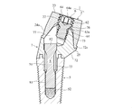
- FIGS. 13 and 14 show an implant keeper and its assembly according to a third embodiment of the present invention.
- This keeper assembly for an implant includes an abutment 7 that is screwed to the implant body 5 using screws 8, and a keeper 1 that is fastened to a head 71 of the abutment 7.
- the keeper 1 includes a keeper body 2 and a two-stage screw member 6.
- the keeper 1 and the implant body 5 itself are the same as those in the second embodiment.
- the abutment 7 is coaxially connected to a head 71 that engages with the keeper body 2, a diameter-expanded portion 72 that is connected to the lower end of the head 71, and a through-hole 77 that extends through the head 71 to expand the abutment 7. And a cylindrical portion 73 protruding from the lower surface 72b of the diameter portion 72.
- the upper surface outer peripheral portion 72 a of the enlarged diameter portion 72 abuts on the bottom edge portion 25 of the keeper 1.
- the head 71 of the abutment 7 has a female thread 75 that opens to the upper end surface 76, and the small-diameter thread 61 of the two-stage screw member 6 is screwed into the female thread 75.
- the upper end surface of the diameter screw portion 62 is substantially flush with or slightly lower than the upper surface 23 of the keeper body 2.
- the through hole 77 into which the screw 8 is inserted opens to the side surface of the head 71.
- the angle ⁇ is preferably within a range of 15 to 35 °, and more preferably 15 to 30 °.
- the screw member 8 After inserting the cylindrical portion 73 of the abutment 7 into the central hole portion 51 of the implant body 5, the screw member 8 is inserted into the through hole 77 of the abutment 7, and the male screw portion 81 of the screw member 8 is inserted into the female screw portion 52 of the implant body 5.
- the abutment 7 is fixed to the implant body 5 when screwed into the implant body 5.
- the method for screwing the keeper 1 to the abutment 7 is the same as in the second embodiment.
Landscapes
- Health & Medical Sciences (AREA)
- Oral & Maxillofacial Surgery (AREA)
- Dentistry (AREA)
- Epidemiology (AREA)
- Life Sciences & Earth Sciences (AREA)
- Animal Behavior & Ethology (AREA)
- General Health & Medical Sciences (AREA)
- Public Health (AREA)
- Veterinary Medicine (AREA)
- Orthopedic Medicine & Surgery (AREA)
- Dental Prosthetics (AREA)
Abstract
Description
(a) 構成
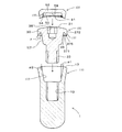
本発明の第一の実施態様によるインプラント用キーパー及びその組立体を図1及び図2に示す。インプラント本体5に固定されるインプラント用キーパー組立体は、インプラント本体5に螺着するアバットメント4と、キーパー1とを具備し、キーパー1は、ネジ穴22を有するキーパー本体2と、キーパー本体2のネジ穴22及びアバットメント4の頭部41のネジ穴45に螺合する二段式ネジ部材3とからなる。
上記インプラント用キーパー1をアバットメント4に固定するには、まず顎骨に埋設されたインプラント本体5のメネジ部52にアバットメント4のオネジ部43を螺合して、インプラント本体5にアバットメント4を固定する。クローバー穴34aに嵌合するドライバを用いて、二段式ネジ部材3の段差部33がアバットメント4の上端面46に当接するまで、二段式ネジ部材3の小径ネジ部31をアバットメント4のメネジ部45に螺合させる。次いで、キーパー本体2をアバットメント4に被せ、キーパー本体2のメネジ部22に二段式ネジ部材3の大径ネジ部32を螺合させる。キーパー本体2の底縁部25がアバットメント4のフランジ部42の上面外周部42aに当接するか、キーパー本体2のテーパ状凹部21がアバットメント4の頭部41の上端面46に当接するまで、キーパー本体2を螺着方向に回転させる。
図7に示すように、キーパー本体2の上面23に義歯の磁気アタッチメント9を磁気的に吸着させることにより、義歯を固定する。磁気アタッチメント9自体は公知のもので良い(例えば、WO 2005/077297号参照)。図7に示す磁気アタッチメント9は、円形断面の凹部を有する軟磁性材料からなるカップ状ヨーク91と、その凹部に収納され、厚さ方向に磁化された円板状の永久磁石92と、凹部を密封するシール板93からなる。シール板93は、永久磁石92を凹部内に封止するとともに磁路となる部材であり、軟磁性材料からなる円板状ヨーク931と、その外周に固着された非磁性材料からなるシールリング932で構成されている。上記軟磁性材料としてはフェライト系ステンレス鋼(例えばSUS447J1)のような耐食性金属が好ましく、上記非磁性材料としてはオーステナイト系ステンレス鋼(例えばSUS316L)のような耐食性金属が好ましい。
(a) 構成
本発明の第二の実施態様によるインプラント用キーパー及びその組立体を図8~図10に示す。第二の実施態様は、キーパー本体2のネジ部材として図11に示す二段式ネジ部材6を用いた点を除いて、基本的に第一の実施態様と同じである。
上記キーパー1をアバットメント4に固定するには、図12(a) に示すようにクローバー穴64aに嵌合した工具Dにより二段式ネジ部材6の小径ネジ部61をアバットメント4のメネジ部45に螺合し、次いで図12(b) に示すように二段式ネジ部材6の第一テーパ部63aがアバットメント4の上端面46に当接するまで二段式ネジ部材6を螺着方向に回転させる。その結果、図12(c) に示すように二段式ネジ部材6の小径ネジ部61のネジ山の上側部分がアバットメント4のメネジ部45のネジ山の下側部分を押圧する状態で、二段式ネジ部材6はアバットメント4に係止される。キーパー本体2のメネジ部22の長さと二段式ネジ部材6の大径ネジ部62の長さを予め設定しておけば、二段式ネジ部材6の第一テーパ部63aのアバットメント4の上端面46への当接により、二段式ネジ部材6の上端面64を正確かつ容易に位置決めできる。また二段式ネジ部材6の第一テーパ部63aのアバットメント4の上端面46への当接により二段式ネジ部材6はアバットメント4に係止されるので、キーパー本体2の螺着の際に二段式ネジ部材6の螺合位置がずれることがない。従って、第一テーパ部63aを係止部と呼ぶことができる。
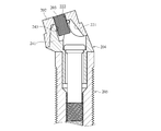
本発明の第三の実施態様によるインプラント用キーパー及びその組立体を図13及び図14に示す。このインプラント用キーパー組立体は、インプラント本体5にネジ8を用いて螺着するアバットメント7と、アバットメント7の頭部71に締着されるキーパー1とを具備する。キーパー1はキーパー本体2及び二段式ネジ部材6からなる。キーパー1及びインプラント本体5自体は第二の実施態様のものと同じである。
Claims (12)
- (a) メネジ部を有するアバットメントの頭部を受承する凹部と、前記凹部と連通するように中央軸線に沿って設けられ、前記アバットメントのメネジ部より大きい呼び径を有するメネジ部とを有する軟磁性材料からなるキーパー本体と、(b) 前記アバットメントのメネジ部と螺合する小径ネジ部と、前記キーパー本体のメネジ部と螺合する大径ネジ部とを有する二段式ネジ部材とを具備し、前記アバットメントのメネジ部に前記小径ネジ部を螺合させ、前記キーパー本体のメネジ部に前記大径ネジ部を螺合させた後、前記キーパー本体を螺着方向に回転させると、前記二段式ネジ部材により前記キーパー本体が前記アバットメントに強固に締着されることを特徴とするインプラント用キーパー。
- 請求項1に記載のインプラント用キーパーにおいて、前記二段式ネジ部材は前記小径ネジ部と前記大径ネジ部との間に段差部又はテーパ部を有し、前記段差部又はテーパ部が前記アバットメントの上端面に係合するまで前記二段式ネジ部材を前記アバットメントの前記メネジ部に螺合させると、前記二段式ネジ部材を軸線方向に正確に位置決めできることを特徴とするインプラント用キーパー。
- 請求項1又は2に記載のインプラント用キーパーにおいて、前記アバットメントの頭部の少なくとも一部は円錐台状であり、かつ前記キーパー本体の凹部の内面は前記アバットメント頭部の円錐台状部と相補的な円錐状であり、もって前記キーパー本体を前記アバットメントに締着したとき前記アバットメント頭部の前記円錐台状部が前記キーパー本体の前記凹部内面に密着することを特徴とするインプラント用キーパー。
- 請求項1~3のいずれかに記載のインプラント用キーパーにおいて、前記キーパー本体の側面部の少なくとも一部がナット状であり、もって前記キーパー本体は前記ナット状側面部に係合する工具を用いて螺着方向に回転自在であることを特徴とするインプラント用キーパー。
- 請求項1~4のいずれかに記載のインプラント用キーパーをアバットメントに固定する方法において、前記アバットメントのメネジ部に前記二段式ネジ部材の小径ネジ部を螺合させるとともに、前記キーパー本体のメネジ部に前記二段式ネジ部材の大径ネジ部を螺合させた後、前記キーパー本体を螺着方向に回転し、前記二段式ネジ部材により前記キーパー本体を前記アバットメントに強固に締着させることを特徴とする方法。
- 請求項5に記載のインプラント用キーパーをアバットメントに固定する方法において、前記二段式ネジ部材は前記小径ネジ部と前記大径ネジ部との間に段差部又はテーパ部を有し、前記段差部又はテーパ部が前記アバットメントの上端面に当接するまで前記二段式ネジ部材の小径ネジ部を前記アバットメントのメネジ部に螺合させた後、前記二段式ネジ部材の大径ネジ部を前記キーパー本体のメネジ部に螺合させ、次いで前記キーパー本体を螺着方向に回転することを特徴とする方法。
- 顎骨に埋設されたインプラント本体に固定するインプラント用キーパー組立体であって、(a) 頭部と、前記頭部の中央軸線に沿って設けられたメネジ部と、前記頭部の下方に延出し前記インプラント本体に螺着されるオネジ部とを有するアバットメントと、(b) 前記アバットメントの頭部を受承する凹部と、前記凹部と連通するように中央軸線に沿って設けられ、前記アバットメントのメネジ部より大きい呼び径を有するメネジ部とを有する軟磁性材料からなるキーパー本体と、(c) 前記アバットメントのメネジ部と螺合する小径ネジ部と、前記キーパー本体のメネジ部と螺合する大径ネジ部とを有し、前記小径ネジ部と前記大径ネジ部との間に段差状の係止部が形成された二段式ネジ部材とを具備し、前記アバットメントのメネジ部に前記二段式ネジ部材の小径ネジ部を螺合させるとともに、前記キーパー本体のメネジ部に前記二段式ネジ部材の大径ネジ部を螺合させた後、前記キーパー本体を螺着方向に回転すると、前記二段式ネジ部材により前記キーパー本体が前記アバットメントに強固に締着されることを特徴とするインプラント用キーパー組立体。
- 請求項7に記載のインプラント用キーパー組立体において、前記二段式ネジ部材は前記小径ネジ部と前記大径ネジ部との間に段差部又はテーパ部を有し、前記段差部又はテーパ部が前記アバットメントの上端面に係合するまで前記二段式ネジ部材を前記アバットメントの前記メネジ部に螺合させると、前記二段式ネジ部材を軸線方向に正確に位置決めできることを特徴とするインプラント用キーパー組立体。
- 請求項7又は8に記載のインプラント用キーパー組立体において、前記アバットメントの頭部の少なくとも一部は円錐台状であり、かつ前記キーパー本体の凹部の内面は前記アバットメント頭部の円錐台状部と相補的な円錐状であり、もって前記キーパー本体を前記アバットメントに締着したとき前記アバットメント頭部の前記円錐台状部が前記キーパー本体の前記凹部内面に密着することを特徴とするインプラント用キーパー組立体。
- 請求項7~9のいずれかに記載のインプラント用キーパー組立体において、前記キーパー本体の側面部の少なくとも一部がナット状であり、前記ナット状側面部に係合する工具を用いて前記キーパー本体を螺着方向に回転することを特徴とするインプラント用キーパー組立体。
- 請求項7~10のいずれかに記載のインプラント用キーパー組立体において、前記アバットメントは前記頭部の下端から半径方向外方に延出するフランジ部を有し、前記フランジ部の上面外周部は前記キーパー本体の外縁部に当接し、前記フランジ部の下面は前記インプラント本体の上端面に当接することを特徴とするインプラント用キーパー組立体。
- 請求項7~11のいずれかに記載のインプラント用キーパー組立体において、前記アバットメントの頭部は前記インプラント本体の中心軸線に対して傾斜しており、かつ前記アバットメントは前記インプラント本体の中央孔部に挿入される円筒部と、前記円筒部から前記頭部の側面まで延びる貫通孔とを有し、前記貫通孔及び前記円筒部を貫通するネジ部材を前記インプラント本体のメネジ部に螺着することにより、前記アバットメントを前記インプラント本体に固定することを特徴とするインプラント用キーパー組立体。
Priority Applications (5)
| Application Number | Priority Date | Filing Date | Title |
|---|---|---|---|
| KR1020137031052A KR101519869B1 (ko) | 2011-05-25 | 2012-05-22 | 임플란트용 키퍼 및 그 조립체, 및 키퍼의 고정 방법 |
| DE112012001947.4T DE112012001947T8 (de) | 2011-05-25 | 2012-05-22 | Anker für ein Implantat und eine diesen enthaltende Baugruppe, sowie Verfahren zum Befestigen des Ankers |
| JP2013516376A JP5761342B2 (ja) | 2011-05-25 | 2012-05-22 | インプラント用キーパー及びその組立体、並びにキーパーの固定方法 |
| CN201280024795.9A CN103561679B (zh) | 2011-05-25 | 2012-05-22 | 植入用定位件及其组装体以及定位件的固定方法 |
| US14/119,691 US8951044B2 (en) | 2011-05-25 | 2012-05-22 | Keeper for implant and its assembly, and keeper-fixing method |
Applications Claiming Priority (2)
| Application Number | Priority Date | Filing Date | Title |
|---|---|---|---|
| JP2011117383 | 2011-05-25 | ||
| JP2011-117383 | 2011-05-25 |
Publications (1)
| Publication Number | Publication Date |
|---|---|
| WO2012161182A1 true WO2012161182A1 (ja) | 2012-11-29 |
Family
ID=47217258
Family Applications (1)
| Application Number | Title | Priority Date | Filing Date |
|---|---|---|---|
| PCT/JP2012/063022 Ceased WO2012161182A1 (ja) | 2011-05-25 | 2012-05-22 | インプラント用キーパー及びその組立体、並びにキーパーの固定方法 |
Country Status (7)
| Country | Link |
|---|---|
| US (1) | US8951044B2 (ja) |
| JP (1) | JP5761342B2 (ja) |
| KR (1) | KR101519869B1 (ja) |
| CN (1) | CN103561679B (ja) |
| DE (1) | DE112012001947T8 (ja) |
| TW (1) | TWI555516B (ja) |
| WO (1) | WO2012161182A1 (ja) |
Cited By (4)
| Publication number | Priority date | Publication date | Assignee | Title |
|---|---|---|---|---|
| JP5553293B1 (ja) * | 2014-01-21 | 2014-07-16 | 優一郎 河原 | 歯科用インプラント |
| JP2015525602A (ja) * | 2012-06-29 | 2015-09-07 | デントーズ カンパニー リミテッドDentoz Co.,Ltd. | 歯科用インプラント |
| JP2023511388A (ja) * | 2020-01-24 | 2023-03-17 | インスティトゥート・シュトラウマン・アーゲー | 歯科修復システムおよび修復物を構築する方法 |
| US11623030B2 (en) | 2012-12-28 | 2023-04-11 | Boston Scientific Scimed, Inc. | Methods, compositions and kits for surgical repair |
Families Citing this family (41)
| Publication number | Priority date | Publication date | Assignee | Title |
|---|---|---|---|---|
| DE102013013565B4 (de) * | 2013-07-17 | 2018-05-24 | Bruno Spindler | Suprastrukturträger und ein Verfahren zu seiner Herstellung |
| DE102013114779A1 (de) * | 2013-12-23 | 2015-06-25 | Bredent Gmbh & Co. Kg | Zahnprothetische Anordnung |
| IL230833A0 (en) * | 2014-02-05 | 2014-09-30 | Ophir Fromovich | bone graft |
| US10182889B2 (en) * | 2014-04-04 | 2019-01-22 | Hitachi Metals, Ltd. | Magnet assembly for dental magnetic attachment |
| CN104546170B (zh) * | 2014-12-11 | 2016-08-17 | 大连三生科技发展有限公司 | 吸磁角度印模转移装置 |
| CN104546164B (zh) * | 2014-12-11 | 2017-09-29 | 大连三生科技发展有限公司 | 橡胶塞角度印模转移装置 |
| CN104546169B (zh) * | 2014-12-11 | 2017-01-18 | 大连三生科技发展有限公司 | 螺栓角度印模转移装置 |
| KR101669893B1 (ko) * | 2015-02-13 | 2016-10-28 | 주식회사 워랜텍 | 임플란트의 2중 구조 어버트먼트 |
| ES2845629T3 (es) * | 2015-02-16 | 2021-07-27 | Sweden & Martina Spa | Implante para prótesis dentales |
| DE102015002948A1 (de) * | 2015-03-10 | 2016-09-15 | Straumann Holding Ag | System zum Modellieren eines implantatgestützten Zahnersatzelements und seine Verwendung |
| CN106264758B (zh) * | 2015-06-26 | 2019-04-09 | 朴永浩 | 一种口腔种植无牙颌修复大角度桥体基台及其使用方法 |
| DE102015118285A1 (de) * | 2015-10-27 | 2017-04-27 | Heraeus Kulzer Gmbh | Scanabutment mit vergrößerter Scanfläche zur genaueren Höhenbestimmung der Implantatauflagefläche |
| ITUB20155840A1 (it) * | 2015-11-04 | 2017-05-04 | Andrea Stocco | Parallelizzatore implantare |
| CN105250039A (zh) * | 2015-11-17 | 2016-01-20 | 陈朋 | 一种口腔种植体及其组件 |
| IL242816B (en) | 2015-11-26 | 2020-06-30 | Mis Implants Tech Ltd | A supporting structure, a covering and a method for connecting them in a multi-unit dental system |
| ITUA20161638A1 (it) * | 2016-03-14 | 2017-09-14 | Sweden & Martina Spa | Sistema migliorato di impianto dentale |
| FR3053240B1 (fr) * | 2016-07-04 | 2021-07-30 | Euroteknika | Embase de pilier pour une restauration dentaire |
| KR20190058452A (ko) * | 2016-07-04 | 2019-05-29 | 스파이널 밸런스, 인코포레이티드 | 척추경 나사용의 결합된 보호 용기 및 전달 디바이스 |
| DE102016215427A1 (de) | 2016-08-17 | 2018-02-22 | Holger Zipprich | Dental-Prothetiksystem und prothetische Konstruktion zur Verwendung mit einem in den Kieferknochen eines Patienten inserierten Dentalimplantat |
| WO2018220612A1 (en) | 2017-05-29 | 2018-12-06 | MIS Implants Technologies Ltd. | Dental connection system |
| DE102017113148A1 (de) * | 2017-06-14 | 2018-12-20 | Bredent Gmbh & Co. Kg | Befestigungsvorrichtung für eine Zahnprothese |
| IT201700076961A1 (it) * | 2017-07-07 | 2019-01-07 | Plan 1 Health Srl | Dispositivo protesico dentale e relativo componente di collegamento intermedio |
| USD840037S1 (en) | 2017-09-05 | 2019-02-05 | MIS Implants Technologies Ltd. | Dental connector |
| USD840039S1 (en) | 2017-09-05 | 2019-02-05 | MIS Implants Technologies Ltd. | Dental connector |
| USD840038S1 (en) | 2017-09-05 | 2019-02-05 | MIS Implants Technologies Ltd. | Dental connector |
| EP3456286B1 (de) * | 2017-09-18 | 2020-04-01 | Bernd Single | Abutment und abutment-system |
| ES2667813B2 (es) * | 2017-12-12 | 2018-08-09 | Julián CUESTA GARCIA | Sistema de fijación dual para prótesis sobre implantes dentales que permite que la prótesis pueda ser atornillada o retenida por clip según convenga |
| DE202017107751U1 (de) * | 2017-12-20 | 2018-12-21 | Straumann Holding Ag | Behälter für ein Zahnimplantat |
| CN108852539B (zh) * | 2018-05-04 | 2020-07-31 | 孙江龄 | 一种牙种植体系统 |
| KR101918654B1 (ko) | 2018-09-19 | 2018-11-15 | 김용서 | 힐링 어버트먼트 및 이를 포함하는 기구 세트 |
| KR200487801Y1 (ko) | 2018-09-19 | 2018-11-05 | 김용서 | 힐링 어버트먼트 및 이를 위한 기구 세트 |
| KR102218969B1 (ko) * | 2018-11-23 | 2021-02-22 | 유창민 | 틀니 임플란트 어셈블리의 틀니지지체 |
| CN110680565B (zh) * | 2019-10-31 | 2025-05-30 | 北京爱康宜诚医疗器材有限公司 | 骨填充假体 |
| CN111658197B (zh) * | 2020-06-23 | 2022-02-11 | 西安交通大学口腔医院 | 一种牙种植体 |
| BR102020022937A2 (pt) * | 2020-11-10 | 2022-05-24 | Jjgc Indústria E Comércio De Materiais Dentários S.A. | Sistema de componentes e implantes dentários contendo configurações geométricas que apenas permitem montagem entre peças correspondentes |
| KR20220071408A (ko) * | 2020-11-24 | 2022-05-31 | 주식회사 디오 | 치과용 컴포넌트와 그 시술용 홀더 |
| FR3120303B1 (fr) * | 2021-03-02 | 2023-04-14 | Biotech Dental | Dispositif prothétique dentaire |
| USD1043324S1 (en) * | 2021-03-05 | 2024-09-24 | M3 Health Industria E Comércio De Produtos Médicos, Odontológicos E Correlatos S.A. | Dental implant device |
| CN113749803A (zh) * | 2021-10-15 | 2021-12-07 | 中国人民解放军空军军医大学 | 一种颌面赝复体固位用磁附着固位装置 |
| BE1031481B1 (nl) * | 2023-04-03 | 2024-11-04 | Dental Vision B V | Aanpasbare tandprothese en werkwijze voor het aanpassen van een dergelijke prothese |
| IL313214A (en) * | 2024-05-29 | 2025-12-01 | Abracadabra Implant Ltd | Magnetic dental implant device and system |
Citations (7)
| Publication number | Priority date | Publication date | Assignee | Title |
|---|---|---|---|---|
| JPS58112536A (ja) * | 1981-09-16 | 1983-07-05 | フイリツプ・ロンカ | 義歯 |
| JPS62284642A (ja) * | 1986-06-02 | 1987-12-10 | 木暮 山人 | 撤去脱着機能を備えた歯科用安定インプラント |
| JPH03121065A (ja) * | 1989-09-15 | 1991-05-23 | Nobelpharma Ab | 隔て部材 |
| US5358367A (en) * | 1992-03-18 | 1994-10-25 | Yang Tai Her | Screw or nut packing micro-adjustment |
| JPH10314186A (ja) * | 1997-05-12 | 1998-12-02 | Shopvest Inc | 作業模型中に取り付けられる臨床歯冠形成用技工用アナログアセンブリ |
| JP2008093126A (ja) * | 2006-10-11 | 2008-04-24 | Hitachi Metals Ltd | インプラント用キーパー |
| JP2009131620A (ja) * | 2007-11-01 | 2009-06-18 | Hitachi Metals Ltd | インプラント用キーパー及びその組立体、並びにキーパーの固定方法 |
Family Cites Families (11)
| Publication number | Priority date | Publication date | Assignee | Title |
|---|---|---|---|---|
| US5658147A (en) | 1995-09-19 | 1997-08-19 | Shopvest, Inc. | Working model for prosthodontic preparation of a crown for installation on an implant fixture |
| US5961329A (en) * | 1997-07-02 | 1999-10-05 | Stucki-Mccormick; Suzanne U. | Combination distraction dental implant and method of use |
| US6325803B1 (en) * | 1998-02-18 | 2001-12-04 | Walter Lorenz Surgical, Inc. | Method and apparatus for mandibular osteosynthesis |
| JP2000024004A (ja) | 1998-07-16 | 2000-01-25 | Aichi Steel Works Ltd | 無歯顎に固定されるインプラント |
| CN1216582C (zh) * | 1999-10-28 | 2005-08-31 | 爱知制钢株式会社 | 义齿磁固位体 |
| US20020123022A1 (en) * | 1999-10-28 | 2002-09-05 | Nicola Pilla | System of securement of dental abutments to dental implants |
| CN1284515C (zh) | 2001-12-27 | 2006-11-15 | 爱知制钢株式会社 | 假齿磁固位体 |
| CN1917828B (zh) | 2004-02-18 | 2012-04-18 | 日立金属株式会社 | 义齿附件及其制造方法 |
| CN2893281Y (zh) * | 2005-12-15 | 2007-04-25 | 董金 | 双丝自锁螺栓和螺母 |
| US20080299515A1 (en) * | 2007-05-29 | 2008-12-04 | Gary Allan Duncan | Duncan transfer screw |
| WO2012045356A1 (de) * | 2010-10-07 | 2012-04-12 | Bredent Gmbh & Co. Kg | Abutment und zahnprothetische anordnung mit einem solchen abutment |
-
2012
- 2012-05-22 US US14/119,691 patent/US8951044B2/en not_active Expired - Fee Related
- 2012-05-22 KR KR1020137031052A patent/KR101519869B1/ko not_active Expired - Fee Related
- 2012-05-22 JP JP2013516376A patent/JP5761342B2/ja not_active Expired - Fee Related
- 2012-05-22 CN CN201280024795.9A patent/CN103561679B/zh not_active Expired - Fee Related
- 2012-05-22 WO PCT/JP2012/063022 patent/WO2012161182A1/ja not_active Ceased
- 2012-05-22 DE DE112012001947.4T patent/DE112012001947T8/de not_active Expired - Fee Related
- 2012-05-24 TW TW101118450A patent/TWI555516B/zh not_active IP Right Cessation
Patent Citations (7)
| Publication number | Priority date | Publication date | Assignee | Title |
|---|---|---|---|---|
| JPS58112536A (ja) * | 1981-09-16 | 1983-07-05 | フイリツプ・ロンカ | 義歯 |
| JPS62284642A (ja) * | 1986-06-02 | 1987-12-10 | 木暮 山人 | 撤去脱着機能を備えた歯科用安定インプラント |
| JPH03121065A (ja) * | 1989-09-15 | 1991-05-23 | Nobelpharma Ab | 隔て部材 |
| US5358367A (en) * | 1992-03-18 | 1994-10-25 | Yang Tai Her | Screw or nut packing micro-adjustment |
| JPH10314186A (ja) * | 1997-05-12 | 1998-12-02 | Shopvest Inc | 作業模型中に取り付けられる臨床歯冠形成用技工用アナログアセンブリ |
| JP2008093126A (ja) * | 2006-10-11 | 2008-04-24 | Hitachi Metals Ltd | インプラント用キーパー |
| JP2009131620A (ja) * | 2007-11-01 | 2009-06-18 | Hitachi Metals Ltd | インプラント用キーパー及びその組立体、並びにキーパーの固定方法 |
Cited By (6)
| Publication number | Priority date | Publication date | Assignee | Title |
|---|---|---|---|---|
| JP2015525602A (ja) * | 2012-06-29 | 2015-09-07 | デントーズ カンパニー リミテッドDentoz Co.,Ltd. | 歯科用インプラント |
| US11623030B2 (en) | 2012-12-28 | 2023-04-11 | Boston Scientific Scimed, Inc. | Methods, compositions and kits for surgical repair |
| US12521470B2 (en) | 2012-12-28 | 2026-01-13 | Boston Scientific Scimed, Inc. | Methods, compositions and kits for surgical repair |
| JP5553293B1 (ja) * | 2014-01-21 | 2014-07-16 | 優一郎 河原 | 歯科用インプラント |
| JP2023511388A (ja) * | 2020-01-24 | 2023-03-17 | インスティトゥート・シュトラウマン・アーゲー | 歯科修復システムおよび修復物を構築する方法 |
| JP7802673B2 (ja) | 2020-01-24 | 2026-01-20 | インスティトゥート・シュトラウマン・アーゲー | 歯科修復システムおよび修復物を構築する方法 |
Also Published As
| Publication number | Publication date |
|---|---|
| US8951044B2 (en) | 2015-02-10 |
| CN103561679B (zh) | 2016-04-27 |
| TW201302168A (zh) | 2013-01-16 |
| CN103561679A (zh) | 2014-02-05 |
| KR20140009523A (ko) | 2014-01-22 |
| JP5761342B2 (ja) | 2015-08-12 |
| DE112012001947T8 (de) | 2014-04-03 |
| DE112012001947T5 (de) | 2014-02-13 |
| KR101519869B1 (ko) | 2015-05-13 |
| TWI555516B (zh) | 2016-11-01 |
| US20140141387A1 (en) | 2014-05-22 |
| JPWO2012161182A1 (ja) | 2014-07-31 |
Similar Documents
| Publication | Publication Date | Title |
|---|---|---|
| JP5761342B2 (ja) | インプラント用キーパー及びその組立体、並びにキーパーの固定方法 | |
| JP5195285B2 (ja) | インプラント用キーパー及びその組立体 | |
| US20030124491A1 (en) | Dental magnetic attachment | |
| KR102040478B1 (ko) | 임플란트 오버 덴처 시스템 및 임플란트 | |
| EP3086739A1 (en) | Self-retaining dental screw | |
| AU2010238532B2 (en) | Dental implant assembly comprising a magnetic temporary screw | |
| TWI584789B (zh) | A magnetic field generating device, and an artificial plant device using the same, and an artificial implant protection denture | |
| JP2008093126A (ja) | インプラント用キーパー | |
| JP2003250816A (ja) | 義歯アタッチメント | |
| US20240407890A1 (en) | Dental screw for osseointegration of bone surface | |
| KR200306036Y1 (ko) | 치과용 자기 부착 시스템 | |
| US20250366954A1 (en) | Magnetic drive system for dental applications and methods | |
| JPH0833652A (ja) | インプラント用磁気式維持装置 | |
| JPH06225889A (ja) | 磁気式義歯維持装置 | |
| JP4179779B2 (ja) | 義歯アタッチメント | |
| US20130203017A1 (en) | Dental implant apparatus, screw for dental implant apparatus and method of making a screw | |
| JP5920323B2 (ja) | 骨成長の促進を図る磁場発生装置と、これを用いたインプラント装置及びインプラント保護用義歯 | |
| AU2011202557B2 (en) | Improved coupling for a multi-part dental implant system | |
| HK1166941B (en) | Dental implant assembly comprising a magnetic temporary screw |
Legal Events
| Date | Code | Title | Description |
|---|---|---|---|
| WWE | Wipo information: entry into national phase |
Ref document number: 201280024795.9 Country of ref document: CN |
|
| 121 | Ep: the epo has been informed by wipo that ep was designated in this application |
Ref document number: 12789008 Country of ref document: EP Kind code of ref document: A1 |
|
| ENP | Entry into the national phase |
Ref document number: 2013516376 Country of ref document: JP Kind code of ref document: A |
|
| ENP | Entry into the national phase |
Ref document number: 20137031052 Country of ref document: KR Kind code of ref document: A |
|
| WWE | Wipo information: entry into national phase |
Ref document number: 14119691 Country of ref document: US |
|
| WWE | Wipo information: entry into national phase |
Ref document number: 1120120019474 Country of ref document: DE Ref document number: 112012001947 Country of ref document: DE |
|
| 122 | Ep: pct application non-entry in european phase |
Ref document number: 12789008 Country of ref document: EP Kind code of ref document: A1 |