WO2012160770A1 - 旋回式作業機械 - Google Patents
旋回式作業機械 Download PDFInfo
- Publication number
- WO2012160770A1 WO2012160770A1 PCT/JP2012/003095 JP2012003095W WO2012160770A1 WO 2012160770 A1 WO2012160770 A1 WO 2012160770A1 JP 2012003095 W JP2012003095 W JP 2012003095W WO 2012160770 A1 WO2012160770 A1 WO 2012160770A1
- Authority
- WO
- WIPO (PCT)
- Prior art keywords
- flow rate
- turning
- motor
- rotational speed
- hydraulic
- Prior art date
Links
Images


Classifications
-
- E—FIXED CONSTRUCTIONS
- E02—HYDRAULIC ENGINEERING; FOUNDATIONS; SOIL SHIFTING
- E02F—DREDGING; SOIL-SHIFTING
- E02F9/00—Component parts of dredgers or soil-shifting machines, not restricted to one of the kinds covered by groups E02F3/00 - E02F7/00
- E02F9/20—Drives; Control devices
- E02F9/22—Hydraulic or pneumatic drives
- E02F9/2278—Hydraulic circuits
- E02F9/2296—Systems with a variable displacement pump
-
- E—FIXED CONSTRUCTIONS
- E02—HYDRAULIC ENGINEERING; FOUNDATIONS; SOIL SHIFTING
- E02F—DREDGING; SOIL-SHIFTING
- E02F9/00—Component parts of dredgers or soil-shifting machines, not restricted to one of the kinds covered by groups E02F3/00 - E02F7/00
- E02F9/08—Superstructures; Supports for superstructures
- E02F9/10—Supports for movable superstructures mounted on travelling or walking gears or on other superstructures
- E02F9/12—Slewing or traversing gears
- E02F9/121—Turntables, i.e. structure rotatable about 360°
- E02F9/123—Drives or control devices specially adapted therefor
-
- E—FIXED CONSTRUCTIONS
- E02—HYDRAULIC ENGINEERING; FOUNDATIONS; SOIL SHIFTING
- E02F—DREDGING; SOIL-SHIFTING
- E02F9/00—Component parts of dredgers or soil-shifting machines, not restricted to one of the kinds covered by groups E02F3/00 - E02F7/00
- E02F9/20—Drives; Control devices
- E02F9/22—Hydraulic or pneumatic drives
- E02F9/2221—Control of flow rate; Load sensing arrangements
- E02F9/2232—Control of flow rate; Load sensing arrangements using one or more variable displacement pumps
- E02F9/2235—Control of flow rate; Load sensing arrangements using one or more variable displacement pumps including an electronic controller
-
- E—FIXED CONSTRUCTIONS
- E02—HYDRAULIC ENGINEERING; FOUNDATIONS; SOIL SHIFTING
- E02F—DREDGING; SOIL-SHIFTING
- E02F9/00—Component parts of dredgers or soil-shifting machines, not restricted to one of the kinds covered by groups E02F3/00 - E02F7/00
- E02F9/20—Drives; Control devices
- E02F9/22—Hydraulic or pneumatic drives
- E02F9/2278—Hydraulic circuits
- E02F9/2285—Pilot-operated systems
-
- G—PHYSICS
- G05—CONTROLLING; REGULATING
- G05B—CONTROL OR REGULATING SYSTEMS IN GENERAL; FUNCTIONAL ELEMENTS OF SUCH SYSTEMS; MONITORING OR TESTING ARRANGEMENTS FOR SUCH SYSTEMS OR ELEMENTS
- G05B11/00—Automatic controllers
- G05B11/01—Automatic controllers electric
- G05B11/14—Automatic controllers electric in which the output signal represents a discontinuous function of the deviation from the desired value, i.e. discontinuous controllers
-
- F—MECHANICAL ENGINEERING; LIGHTING; HEATING; WEAPONS; BLASTING
- F15—FLUID-PRESSURE ACTUATORS; HYDRAULICS OR PNEUMATICS IN GENERAL
- F15B—SYSTEMS ACTING BY MEANS OF FLUIDS IN GENERAL; FLUID-PRESSURE ACTUATORS, e.g. SERVOMOTORS; DETAILS OF FLUID-PRESSURE SYSTEMS, NOT OTHERWISE PROVIDED FOR
- F15B9/00—Servomotors with follow-up action, e.g. obtained by feed-back control, i.e. in which the position of the actuated member conforms with that of the controlling member
- F15B9/02—Servomotors with follow-up action, e.g. obtained by feed-back control, i.e. in which the position of the actuated member conforms with that of the controlling member with servomotors of the reciprocatable or oscillatable type
- F15B9/03—Servomotors with follow-up action, e.g. obtained by feed-back control, i.e. in which the position of the actuated member conforms with that of the controlling member with servomotors of the reciprocatable or oscillatable type with electrical control means
-
- F—MECHANICAL ENGINEERING; LIGHTING; HEATING; WEAPONS; BLASTING
- F15—FLUID-PRESSURE ACTUATORS; HYDRAULICS OR PNEUMATICS IN GENERAL
- F15B—SYSTEMS ACTING BY MEANS OF FLUIDS IN GENERAL; FLUID-PRESSURE ACTUATORS, e.g. SERVOMOTORS; DETAILS OF FLUID-PRESSURE SYSTEMS, NOT OTHERWISE PROVIDED FOR
- F15B9/00—Servomotors with follow-up action, e.g. obtained by feed-back control, i.e. in which the position of the actuated member conforms with that of the controlling member
- F15B9/14—Servomotors with follow-up action, e.g. obtained by feed-back control, i.e. in which the position of the actuated member conforms with that of the controlling member with rotary servomotors
-
- G—PHYSICS
- G05—CONTROLLING; REGULATING
- G05B—CONTROL OR REGULATING SYSTEMS IN GENERAL; FUNCTIONAL ELEMENTS OF SUCH SYSTEMS; MONITORING OR TESTING ARRANGEMENTS FOR SUCH SYSTEMS OR ELEMENTS
- G05B2219/00—Program-control systems
- G05B2219/30—Nc systems
- G05B2219/45—Nc applications
- G05B2219/45012—Excavator
-
- Y—GENERAL TAGGING OF NEW TECHNOLOGICAL DEVELOPMENTS; GENERAL TAGGING OF CROSS-SECTIONAL TECHNOLOGIES SPANNING OVER SEVERAL SECTIONS OF THE IPC; TECHNICAL SUBJECTS COVERED BY FORMER USPC CROSS-REFERENCE ART COLLECTIONS [XRACs] AND DIGESTS
- Y10—TECHNICAL SUBJECTS COVERED BY FORMER USPC
- Y10T—TECHNICAL SUBJECTS COVERED BY FORMER US CLASSIFICATION
- Y10T137/00—Fluid handling
- Y10T137/8593—Systems
- Y10T137/85978—With pump
- Y10T137/85986—Pumped fluid control
- Y10T137/86027—Electric
Definitions
- the present invention relates to a swivel work machine such as an excavator.
- a general excavator includes a crawler type lower traveling body 1, an upper revolving body 2 mounted on the crawler-type lower traveling body 1 around an axis X perpendicular to the ground, and an upper portion thereof. And a drilling attachment 3 attached to the revolving structure 2.
- the excavation attachment 3 moves the boom 4, the arm 5 attached to the tip of the boom 4, the bucket 6 attached to the tip of the arm 5, and the boom 4, the arm 5, and the bucket 6.
- swing motors including left and right traveling motors for driving the left and right crawlers of the lower traveling body 1 and a hydraulic motor for driving the upper swing body 2 to rotate. .
- a hydraulic pump as a hydraulic source
- a remote control valve as an operating device
- supply of hydraulic oil from the hydraulic pump to each actuator based on the operation and supply of hydraulic oil from the actuator
- a control valve that operates to control the discharge is used to control the direction and speed of operation of each actuator.
- the actuator circuit constructed for each actuator is provided with a main relief valve (hereinafter simply referred to as a relief valve) between the pump discharge line and the tank so that circuit piping and equipment are not damaged by high pressure. When the circuit pressure exceeds the relief pressure, the main relief valve opens to release the pressure oil to the tank.
- a main relief valve hereinafter simply referred to as a relief valve
- the discharge flow rate of the pump (hereinafter referred to as pump flow rate) is the operation amount of the remote control valve (hereinafter referred to as pump flow rate).
- pump flow rate the discharge flow rate of the pump
- pump flow rate the operation amount of the remote control valve
- the so-called positive control is often employed as the turning operation amount increases.
- the difference between the pump flow rate determined by the swing operation amount and the motor flow rate actually used for the rotation of the swing motor, that is, the swing flow rate is the surplus flow rate that is the flow rate of hydraulic oil discarded from the relief valve to the tank. Yes, the higher the surplus flow rate, that is, the relief flow rate, the lower the energy efficiency of the hydraulic pump.
- the relief flow rate is estimated from the pump pressure at the time of turning and the pressure characteristics of the relief valve so that this estimated value becomes zero.
- Techniques for controlling the pump flow rate are known.
- the pressure characteristics themselves that are the basis for the estimation have variations among relief valves and variations due to temperature. It is difficult to obtain an estimated value with high accuracy. This may lead to a decrease in work efficiency due to an insufficient turning speed due to insufficient flow rate, and conversely a decrease in energy saving effect due to an increase in excess flow rate due to excessive flow rate.
- An object of the present invention is to provide a swivel work machine capable of accurately obtaining a surplus flow rate and appropriately performing flow control of a swivel drive hydraulic pump.
- the swing type work machine provided by the present invention is configured to drive the upper swing body by receiving the lower traveling body, the upper swing body that is pivotably mounted on the lower traveling body, and the supply of hydraulic oil.
- a swivel motor that is a hydraulic motor that operates on the motor, a variable displacement hydraulic pump that supplies the swivel motor with the hydraulic oil, a pump regulator that changes the discharge flow rate of the hydraulic pump, and a command for the swivel drive
- a turning operation device that includes an operation member that is operated to input the operation signal and outputs an operation signal corresponding to the operation of the operation member, and supply of hydraulic oil to the turning motor based on the operation signal of the turning operation device And a control valve that operates to control the discharge of hydraulic oil from the swing motor, and a surplus of the hydraulic oil discharged from the hydraulic pump to the tank A relief valve, an operation detector for detecting an operation direction and an operation amount of an operation member of the turning operation device, a motor rotation number detector for detecting the rotation number of the turning motor, and a discharge flow rate of the hydraulic pump.
- a controller that commands the pump regulator includes a target rotational speed of the swing motor that is obtained from an operation amount of an operation member of the swing operation device, and a rotation speed of the swing motor that is detected by the motor speed detector.
- a deviation from the actual rotational speed, that is, a value corresponding to the surplus flow rate that is the surplus hydraulic oil flow rate is obtained, and the discharge flow rate of the hydraulic pump is controlled so that this deviation approaches zero.
- FIG. 1 It is a figure which shows the turning circuit which concerns on embodiment of this invention. It is a block diagram which shows the content of the arithmetic control which the controller which concerns on the said embodiment performs. It is a figure which shows the relationship between the turning operation amount and the target rotation speed in the said embodiment. It is a figure for demonstrating changing a gain according to the magnitude of turning operation amount in the said embodiment. It is a figure for demonstrating the low-order selection of the electric current value based on the 2nd positive control in the said embodiment, and the electric current value based on the 1st positive control. It is a side view which shows a general shovel.
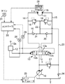
- FIG. 1 shows a turning circuit according to an embodiment of the present invention, that is, a circuit for driving the upper turning body 2 shown in FIG. 6 to turn.
- This circuit is a hydraulic pump 10 as a hydraulic source driven by an engine (not shown), and a turning hydraulic motor that rotates by the supply of hydraulic oil discharged from the hydraulic pump 10 to turn the upper swing body 2.
- a turning motor 11 and a remote control valve 12 as a turning operation device including a lever 12 a operated to input a turning drive command, a hydraulic pump 10, a tank T, and the turning motor 11 are provided.
- a control valve 13 which is a hydraulic pilot type switching valve that can be operated by the remote control valve 12.
- the turning motor 11 has a left port 11a and a right port 11b, which are a first port and a second port, respectively.
- a left port 11a and a right port 11b which are a first port and a second port, respectively.
- When hydraulic oil is supplied from the left port 11a it is discharged from the right port 11b.
- the upper turning body 2 shown in FIG. 3 is discharged from the left port 11a to turn the upper turning body 2 to the right.
- the lever 12a of the remote control valve 12 is operated between a neutral position and a left and right turning position, and the remote control valve 12 outputs a pilot pressure having a magnitude corresponding to an operation amount from a port corresponding to the operation direction.
- the control valve 13 is switched from the neutral position 13 a shown in the figure to the left turning position 13 b or the right turning position 13 c, whereby the hydraulic oil is supplied to the turning motor 11 and left and right discharges from the turning motor 11.
- the direction and the flow rate of the hydraulic oil are controlled. In other words, switching of the turning state, that is, switching to each state of acceleration (including start-up), steady operation at a constant speed, deceleration, and stop, and control of the turning direction and the turning speed are performed.
- This circuit includes a left turn pipeline 14 and a right turn pipeline 15, which are a first pipeline and a second pipeline, respectively, a relief valve circuit 18, a check valve circuit 21, a communication passage 22, and a makeup line. 23 and a main relief valve 27 for regulating the circuit pressure below a set value.
- the left turning conduit 14 connects the control valve 13 and the left port 11 a of the turning motor 11, and the right turning conduit 15 connects the control valve 13 and the right port 11 b of the turning motor 11.
- the relief valve circuit 18, the check valve circuit 21, and the communication path 22 are provided between the two swirl conduits 14 and 15.
- the relief valve circuit 18 is provided so as to connect the two swirl lines 14 and 15 to each other.
- the relief valve circuit 18 includes a pair of relief valves 16 and 17 corresponding to brake valves, and these relief valves 16 and 17 are arranged so that their outlets face each other and are connected to each other.
- the check valve circuit 21 is provided in parallel with the relief valve circuit 18 so as to connect the two turning conduits 14 and 15 at a position closer to the turning motor 11 than the relief valve circuit 18.
- the check valve circuit 21 includes a pair of check valves 19 and 20, and these check valves 19 and 20 are arranged so that their inlets face each other and are connected to each other.
- the communication path 22 includes a portion located between the relief valves 16 and 17 in the relief valve circuit 18 and a portion located between the check valves 19 and 20 in the check valve circuit 21. Connecting.
- the makeup line 23 connects the communication path 22 to the tank T in order to suck up hydraulic oil. This makeup line 23 is provided with a back pressure valve 24.
- the control valve 13 blocks both the turning conduits 14 and 15 from the pump 10 and does not rotate the turning motor 11.
- the control valve 13 is switched to the left turning position 13b or the right turning position 13c, and the hydraulic pump 10 to the left turning pipeline 14 or The supply of pressure oil to the right turning pipeline 15 is allowed.
- the swing motor 11 rotates left or right to turn the upper swing body 2 to turn, that is, in an acceleration or steady operation state.
- the oil discharged from the turning motor 11 returns to the tank T via the control valve 13.
- the main relief valve 27 is opened to return excess hydraulic oil to the tank T.
- the remote control valve 12 when the remote control valve 12 is decelerated during the right turn driving, that is, when the lever 12a is returned to the neutral position or operated in the direction to return to the neutral position, the pressure oil to the turning motor 11 is restored. And the return of oil from the turning motor 11 to the tank T are stopped, or the flow rate of the supplied hydraulic oil and the flow rate of the return oil are reduced.
- the swing motor 11 since the swing motor 11 continues to turn right due to the inertia of the upper swing body 2, pressure is applied to the left turn conduit 14 on the meter-out side, and when this reaches a certain value, the relief valve 16 on the left side of the figure is turned on. As shown by the broken line arrow in FIG.
- the oil in the left turning pipeline 14 opens the relief valve 16, the communication passage 22, the check valve 20 on the right side of the drawing, and the right turning pipeline (meter-in side pipeline) 15. It passes in order and flows into the turning motor 11.
- the swing motor 11 is decelerated and stopped by receiving the hydraulic braking force by the relief action while inertially rotating. The same applies to deceleration / stop from a left turn.
- the tank oil is sucked into the turning pipeline 14 or 15 through the route of the makeup line 23, the communication passage 22, and the check valve circuit 21. Cavitation is prevented.
- the hydraulic pump 10 is a variable displacement hydraulic pump that has a variable tilt angle and changes the discharge flow rate according to the change in the tilt angle.
- the circuit according to this embodiment is configured to change the tilt angle of the hydraulic pump 10 and the discharge flow rate that is the flow rate of the hydraulic oil discharged, and by inputting a flow rate command to the pump regulator 25.
- a controller 26 that controls the discharge flow rate of the hydraulic pump 10, pilot pressure sensors 28 and 29 that are operation detectors, a rotation speed sensor 30 that is a motor rotation speed detector, and a gain adjuster 31 are further provided.
- the pilot pressure sensors 28 and 29 detect the pilot pressure output from the remote control valve 12 as a turning operation amount, and output an operation detection signal corresponding to the pilot pressure.
- the rotation speed sensor 30 detects the rotation speed of the turning motor 11 and outputs a rotation speed detection signal corresponding to the rotation speed.
- the controller 26 determines the necessary pump flow rate, that is, the hydraulic pump 10. A discharge flow rate and a pump tilt angle for obtaining the pump flow rate are calculated, and a command is given to the pump regulator 25 to adjust the actual tilt angle to the calculated pump tilt angle.
- the gain adjuster 31 is operated by an operator to arbitrarily change a gain (proportional constant) set by the controller 26 for calculating the pump flow rate manually or manually, and a gain adjustment signal corresponding to the operation. Is input to the controller 26.
- the controller 26 basically performs positive control for the turning circuit. Specifically, first, the primary target rotation speed nt1, which is the target rotation speed of the swing motor 11 in accordance with the swing operation amount, is set to a characteristic of pilot pressure (turn operation amount) / target rotation speed set in advance as shown in FIG. And the actual rotational speed nr which is the actual rotational speed of the turning motor 11 detected by the rotational speed sensor 30 is compared. That is, a deviation ⁇ between the target rotational speed nt1 and the actual rotational speed nr is obtained, and a corrected rotational speed nre is calculated by multiplying the deviation ⁇ by a gain in step S1.
- the left graph in FIG. 4 is for the case where the turning operation amount is large, the right graph is for the case where the turning operation amount is small, the first graph from the top is the time change of the pilot pressure, the second graph is the primary target rotation.
- the time change of the number nt1 and the actual rotational speed nr the third stage shows the time change of the gain, and the fourth stage shows the time change of the pump flow rate.
- the value of the pilot pressure output from the remote control valve 12 and the rising angle thereof vary depending on the magnitude of the turning operation amount.
- the deviation ⁇ between the initial primary target rotational speed ntl and the actual rotational speed nt1 increases as the turning operation amount increases. Therefore, in normal positive control, when the turning operation amount is large, the pump flow rate increases rapidly and the surplus flow rate increases, and conversely, when the turning operation amount is small, the followability of the pump flow rate deteriorates.
- the gain is decreased to lower the pump flow rate, and when the turning operation amount is small, the gain is increased to increase the pump flow rate, thereby increasing 4
- the amount of turning operation is large, it is possible to reduce the energy loss by suppressing the generation of surplus flow, and when the amount of turning operation is small, follow-up performance of the pump flow rate, that is, the response of the actuator. Can be better.
- the magnitude of the gain is automatically set by the controller 26 according to the magnitude of the turning operation amount. In this embodiment, the operator manually operates the gain adjuster 31 to operate the operator. It is also possible to select and change according to the user's preference and application.
- the controller 26 adds the corrected rotational speed nre to the actual rotational speed nr to obtain the secondary target rotational speed nt2, and further, the motor flow rate (swing flow rate) for obtaining this target secondary rotational speed nt2. ) Find Qs.
- step S3 the controller 26 obtains the pump tilt angle qs for obtaining the swirling flow rate Qs, and further in step S4, the controller 26 sends the pump regulator 25 to the pump regulator 25 in order to realize the pump tilt angle qs.
- a first positive control current ip1 that is a current to be supplied is obtained.
- the controller 26 separately supplies a pump flow rate ⁇ swing flow rate ⁇ pump tilt angle for realizing the primary target rotation speed nr1 based on the primary target rotation speed nr1 which is a target rotation speed determined only by the swing operation amount.
- the second positive control current ip2 is calculated by sequentially calculating and the low-order selection between the first positive control current ip1 and the second positive control current ip2 is performed in step S5.
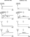
- FIG. 5 shows changes in pilot pressure, target rotation speed, current value, and actual rotation speed when the vehicle is decelerated and stopped during turning.
- first positive control means a control unique to the present invention for multiplying the deviation ⁇ by a gain
- second positive control is a target rotational speed based on only a turning operation amount, which has been conventionally performed. It means the control that decides.
- the upper left graph in FIG. 5 relates to the second positive control, and the right graph relates to the first positive control.
- the target rotational speed and the positive control current are reduced from the time of the operation.
- the rotational speed nr gradually decreases and the turning stops.
- the second positive control when the lever 12a reaches the neutral position, the positive control current is minimized, and the turning of the upper swing body 2 is stopped after a slight time lag from that point, whereas the first positive control is stopped.
- the control since the actual rotational speed is fed back, it takes more time than the second positive control to reduce the current value and the actual rotational speed nr, and the turning stop is delayed.
- the value of the second positive control current ip2 lower than the value of the first positive control current ip1 is selected, so that the actual rotational speed nr is quickly reduced as shown in the lowermost graph of FIG. To stop turning.
- selecting a value of the first positive control current ip1 that is relatively low enables a reduction in excess flow rate.
- the flow rate control of the pump so as to make it close to 0 is more appropriate based on the surplus flow rate, which is more accurate than the known technology that controls the pump flow rate based on the estimated value of the relief flow rate.
- the flow rate can be controlled, and thereby it is possible to suppress the excessive flow rate at the time of turning and increase the energy efficiency.
- the controller 26 obtains a corrected rotational speed nre by multiplying the deviation ⁇ between the primary target rotational speed nt1 and the actual rotational speed nr obtained from the turning operation amount by a smaller gain as the turning operation amount increases. Since the turning flow rate Qs to be supplied to the turning motor 11 is obtained based on the secondary target rotation speed nt2 determined by the sum of the corrected rotation speed nre and the actual rotation speed nr, the turning operation amount is large during acceleration including startup. In this case, an increase in the pump flow rate is suppressed and the excess flow rate is reduced. On the other hand, when the turning operation amount is small, speed followability can be improved.
- the low selection between the value of the first positive control current ip1 and the second positive control current ip2 is to obtain a high energy saving effect during acceleration and to provide high responsiveness during deceleration stop. Make both possible.
- the present invention includes an aspect in which the lower selection is not performed, and even in this aspect, the basic object of the present invention of accurately obtaining the excess flow rate can be achieved.
- the revolving work machine according to the present invention is not limited to an excavator.
- the present invention can also be applied to other swivel work machines such as a dismantling machine and a crusher configured by using a base of an excavator.
- the swing type work machine includes a lower traveling body, an upper swing body that is pivotably mounted on the lower traveling body, and a hydraulic motor that operates to drive the upper swing body by receiving supply of hydraulic oil.
- a turning operation device including an operation member to be operated and outputting an operation signal corresponding to the operation of the operation member; supply of hydraulic oil to the turning motor based on the operation signal of the turning operation device; and from the turning motor
- a control valve that operates to control the discharge of the hydraulic oil, a relief valve that returns a surplus of the hydraulic oil discharged from the hydraulic pump to the tank,
- An operation detector that detects an operation direction and an operation amount of an operation member of the turning operation device, a motor rotation number detector that detects the rotation number of the turning motor, and commands a discharge flow rate of the hydraulic pump to the pump regulator
- the controller includes a target rotational speed of the swing motor determined from an operation amount of an operation member of the swing operation device, and an actual rotational speed of the swing motor detected by the motor rotational speed detector.
- a deviation that is, a value corresponding
- the controller calculates a deviation between the target rotational speed and the actual rotational speed, or a deviation calculating section that calculates a value corresponding thereto, and the discharge flow rate of the hydraulic pump so that the calculated value approaches 0.
- a discharge flow rate controller for controlling.
- the difference between the target rotational speed of the swing motor corresponding to the swing operation amount and the detected actual rotational speed, that is, the value corresponding to the surplus flow rate, and the pump flow rate control for making this close to 0 are:
- it is possible to perform appropriate flow rate control based on the surplus flow rate which is more accurate than the known technology that controls the pump flow rate based on the estimated value of the relief flow rate. Thereby, it becomes possible to suppress the excessive flow volume at the time of turning and to improve energy efficiency.
- the controller determines a smaller gain as the turning operation amount that is the operation amount of the operation member of the turning operation device is larger, and the primary target rotation speed that is the target rotation speed obtained from the turning operation amount and the actual target rotation speed.
- a correction rotational speed is obtained by multiplying the deviation from the rotational speed by the gain, and a swing flow rate to be supplied to the swing motor is determined from a secondary target rotational speed determined by the sum of the corrected rotational speed and the actual rotational speed.
- the discharge flow rate of the hydraulic pump is controlled so that the flow rate is obtained.
- the discharge flow rate control unit has a gain setting unit that sets a smaller gain as the turning operation amount that is the operation amount of the operation member of the turning operation device is larger, and a target rotation speed that is obtained from the turning operation amount. From the secondary target rotational speed determined by the sum of the corrected rotational speed and the actual rotational speed, the corrected rotational speed determining section that obtains the corrected rotational speed by multiplying the deviation between a certain primary rotational speed and the actual rotational speed by the gain. There is provided a turning flow rate determining unit for obtaining a turning flow rate to be supplied to the turning motor, and a discharge flow rate adjusting unit for adjusting the discharge flow rate of the hydraulic pump based on the turning flow rate determining unit.
- the calculation control including the gain setting based on the turning operation amount makes it possible to obtain an appropriate flow rate characteristic according to the turning operation amount. Specifically, especially at the time of turning acceleration including start-up, the deviation increases as the turning operation amount increases, and the surplus flow rate increases. Therefore, as the turning operation amount increases, the deviation is multiplied by a smaller gain to obtain a pump flow rate. By suppressing the increase in the flow rate, the excess flow rate can be reduced. On the other hand, if the motor speed change tends to be delayed with respect to the increase in the pump flow rate, and the amount of turning operation is small, speed gain can be improved by using a large gain. can do.
- the controller determines, as a value corresponding to the discharge flow rate of the hydraulic pump, only based on the first value obtained based on the operation amount and deviation of the turning operation means and the operation amount of the turning operation means. It is preferable to perform a low-order selection with respect to the second value, and control the discharge flow rate of the hydraulic pump with the selected value as a target. This makes it possible to execute an appropriate flow rate control according to turning acceleration and deceleration stop.
- selecting the first value based on feedback control that brings the deviation closer to 0 makes it possible to quickly set the surplus flow rate to 0 and obtain a high energy saving effect, while at the time of deceleration stop
- the second value based on the positive control control corresponding to the turning operation amount is selected (because the operation amount is 0, the pump flow rate becomes 0)
- the pump flow rate continues to be output until the actual rotational speed of the turning motor becomes 0. It is possible to stop the turning of the upper-part turning body more quickly, that is, increase the response of the stop, compared to the conventional control as described above, that is, the control based on the first value.
Abstract
旋回式作業機械は、旋回駆動用の油圧モータである旋回モータ11と、可変容量型油圧ポンプ10と、操作部材12aを含む旋回操作装置12と、その操作信号に基づいて旋回モータ11を制御するコントロールバルブ13と、ポンプレギュレータ25と、余剰油をタンクTに逃がすリリーフ弁27と、操作部材12aの操作方向及び操作量を検出する操作検出器28,29と、モータ回転数検出器30と、油圧ポンプ10の吐出流量を制御するコントローラ26と、を備える。コントローラ26は、旋回操作量から求められる旋回モータ11の目標回転数と、モータ回転数検出器30が検出する実回転数との偏差を求め、この偏差を0に近づけるように吐出流量を制御する。
Description
本発明は、ショベル等の旋回式作業機械に関するものである。
本発明の背景技術を、ショベルを例にとって説明する。
一般的なショベルは、例えば図6に示すように、クローラ式の下部走行体1と、その上に地面に対して鉛直な軸Xまわりに旋回自在に搭載される上部旋回体2と、この上部旋回体2に装着される掘削アタッチメント3と、を備える。掘削アタッチメント3は、起伏自在なブーム4と、このブーム4の先端に取付けられたアーム5と、このアーム5の先端に取付けられたバケット6と、前記ブーム4、アーム5及びバケット6をそれぞれ動かすためのシリンダ(油圧シリンダ)であるブームシリンダ7、アームシリンダ8及びバケットシリンダ9と、を有する。さらに、これらのシリンダ7~9以外の油圧アクチュエータとして、下部走行体1の左右のクローラを駆動する左右の走行モータと、上部旋回体2を旋回駆動するための油圧モータからなる旋回モータが設けられる。
前記各アクチュエータを動かすために、その油圧源である油圧ポンプと、操作装置であるリモコン弁と、その操作に基づいて前記油圧ポンプから各アクチュエータへの作動油の供給及び当該アクチュエータからの作動油の排出を制御するように作動するコントロールバルブと、が用いられ、これらによって各アクチュエータの作動方向と作動速度が制御される。前記各アクチュエータについて構築されるアクチュエータ回路には、回路配管や機器が高圧によって破損することのないようにポンプ吐出管路とタンクとの間にメインリリーフ弁(以下、単にリリーフ弁という)が設けられ、このメインリリーフ弁は回路圧がリリーフ圧を超えると開弁して圧油をタンクに逃がす。
前記アクチュエータ回路のうち、旋回モータを駆動するための旋回回路については、前記油圧ポンプとして可変容量ポンプが用いられるとともに、このポンプの吐出流量(以下、ポンプ流量という)をリモコン弁の操作量(以下、旋回操作量という)が大きいほど多くするような、いわゆるポジティブコントロールがしばしば採用される。この場合、前記旋回操作量で決まるポンプ流量と、前記旋回モータの回転に実際に使用されるモータ流量すなわち旋回流量との差が、リリーフ弁からタンクに捨てられる作動油の流量である余剰流量であり、この余剰流量すなわちリリーフ流量が多いほど油圧ポンプのエネルギー効率が悪い。
従来、この余剰流量を抑制するために、特許文献1に示されているように、旋回時のポンプ圧とリリーフ弁の圧力特性とからリリーフ流量を推定し、この推定値が0になるようにポンプ流量を制御する技術が公知である。しかし、このようにリリーフ弁の圧力特性をもとにリリーフ流量すなわち余剰流量を「推定」する技術では、推定の根拠となる圧力特性そのものにリリーフ弁ごとのばらつきや温度によるばらつきがあることから、高い精度で推定値を得ることは困難である。このことは、流量不足に伴う不十分な旋回速度に起因する作業能率の低下や、逆に流量過多に伴う余剰流量の増大に起因する省エネ効果の低下を招くおそれがある。
本発明の目的は、余剰流量を正確に求めて旋回駆動用の油圧ポンプの流量制御を適切に行うことができる旋回式作業機械を提供することである。本発明により提供される旋回式作業機械は、下部走行体と、この下部走行体上に旋回自在に搭載された上部旋回体と、作動油の供給を受けることにより上部旋回体を旋回駆動するように作動する油圧モータである旋回モータと、この旋回モータに前記作動油を供給するための可変容量型の油圧ポンプと、この油圧ポンプの吐出流量を変化させるポンプレギュレータと、前記旋回駆動についての指令を入力するために操作される操作部材を含み、この操作部材の操作に対応した操作信号を出力する旋回操作装置と、この旋回操作装置の操作信号に基づいて前記旋回モータへの作動油の供給及び前記旋回モータからの作動油の吐出を制御するように作動するコントロールバルブと、前記油圧ポンプから吐出される作動油のうちの余剰分をタンクに戻すリリーフ弁と、前記旋回操作装置の操作部材の操作方向及び操作量を検出する操作検出器と、前記旋回モータの回転数を検出するモータ回転数検出器と、前記油圧ポンプの吐出流量を前記ポンプレギュレータに指令するコントローラとを備え、このコントローラは、前記旋回操作装置の操作部材の操作量から求められる前記旋回モータの目標回転数と、前記モータ回転数検出器によって検出される前記旋回モータの実回転数との偏差、すなわち前記余剰分の作動油の流量である余剰流量に相当する値、を求め、この偏差を0に近づけるように前記油圧ポンプの吐出流量を制御するものである。
本発明の実施形態を説明する。この実施形態は、前記の背景技術と同じく、図6に示すショベルを適用対象としている。
図1は、本発明の実施形態に係る旋回回路、すなわち図6に示される上部旋回体2を旋回駆動するための回路を示す。この回路は、図示しないエンジンによって駆動される油圧源としての油圧ポンプ10と、この油圧ポンプ10から吐出された作動油の供給により回転して上部旋回体2を旋回駆動する旋回用の油圧モータである旋回モータ11と、その旋回駆動の指令を入力するために操作されるレバー12aを含む、旋回操作装置としてのリモコン弁12と、油圧ポンプ10及びタンクTと旋回モータ11との間に設けられ、前記リモコン弁12により操作されることが可能な油圧パイロット式の切換弁であるコントロールバルブ13と、を含む。
前記旋回モータ11は、それぞれ第1ポート及び第2ポートである左ポート11a及び右ポート11bを有し、左ポート11aから作動油が供給されるときはこれを右ポート11bから吐出して図6に示す上部旋回体2を左旋回させ、逆に右ポート11bから作動油が供給されるときはこれを左ポート11aから吐出して前記上部旋回体2を右旋回させる。
前記リモコン弁12のレバー12aは、中立位置と左右の旋回位置との間で操作され、リモコン弁12はその操作方向に対応するポートから操作量に対応した大きさのパイロット圧を出力する。このパイロット圧によりコントロールバルブ13が図示の中立位置13aから左旋回位置13bまたは右旋回位置13cに切換えられ、これにより、旋回モータ11への作動油の供給方向及び旋回モータ11からの左右の吐出方向と、その作動油の流量とが制御される。換言すれば、旋回状態の切換、すなわち(起動を含む)加速、速度一定での定常運転、減速、停止の各状態への切換と、旋回方向および旋回速度の制御と、が行われる。
この回路は、それぞれ第1管路及び第2管路である左旋回管路14及び右旋回管路15と、リリーフ弁回路18と、チェック弁回路21と、連通路22と、メイクアップライン23と、回路圧を設定値以下に規制するためのメインリリーフ弁27と、を含む。
左旋回管路14は前記コントロールバルブ13と旋回モータ11の左ポート11aとを接続し、右旋回管路15は前記コントロールバルブ13と前記旋回モータ11の右ポート11bとを接続する。前記リリーフ弁回路18、チェック弁回路21、及び連通路22は、両旋回管路14,15同士の間に設けられている。
前記リリーフ弁回路18は、両旋回管路14,15同士を接続するように設けられる。このリリーフ弁回路18は、ブレーキ弁に相当する一対のリリーフ弁16,17を含み、これらのリリーフ弁16,17がその出口同士が互いに対向し且つ接続されるように配置されている。
前記チェック弁回路21は、前記リリーフ弁回路18よりも前記旋回モータ11に近い位置で両旋回管路14,15同士を接続するように当該リリーフ弁回路18と並列状態で設けられる。このチェック弁回路21は、一対のチェック弁19,20を含み、これらのチェック弁19,20がその入口同士が互いに対向しかつ接続されるように配置されている。
前記連通路22は、前記リリーフ弁回路18のうち両リリーフ弁16,17同士の間に位置する部位と、前記チェック弁回路21のうち両チェック弁19,20同士の間に位置する部位とを接続する。前記メイクアップライン23は、作動油を吸い上げるために前記連通路22をタンクTに接続する。このメイクアップライン23には背圧弁24が設けられている。
この装置において、リモコン弁12が操作されないとき、すなわちそのレバー12aが中立位置にあるときはコントロールバルブ13が図1に示される中立位置13aに保持される。この状態からレバー12aが操作されると、コントロールバルブ13は中立位置13aから図左側の位置(左旋回位置)13bまたは右側の位置(右旋回位置)13cにその操作量に応じたストロークで作動する。
コントロールバルブ13は、前記中立位置13aでは、両旋回管路14,15をポンプ10からブロックし、旋回モータ11を回転させない。この状態からリモコン弁12のレバー12aが左または右旋回側に操作されると、コントロールバルブ13は左旋回位置13bまたは右旋回位置13cに切換えられて油圧ポンプ10から左旋回管路14または右旋回管路15への圧油の供給を許容する。これにより、旋回モータ11が左または右に回転して上部旋回体2を旋回駆動する状態、すなわち加速または定常運転状態となる。このとき、旋回モータ11から吐出された油はコントロールバルブ13を経由してタンクTに戻る。旋回中に回路圧が設定値を超えたときは前記メインリリーフ弁27が開いて余剰の作動油をタンクTに戻す。
一方、たとえば右旋回駆動中にリモコン弁12が減速操作されると、すなわち、そのレバー12aが中立位置に戻され、または中立位置に戻る方向に操作されると、旋回モータ11への圧油の供給及び旋回モータ11からタンクTへの油の戻りが停止し、あるいはその供給される作動油の流量及び戻り油の流量が減少する。その一方、旋回モータ11は上部旋回体2の慣性によって右旋回を続けるため、そのメータアウト側である左旋回管路14に圧力が立ち、これが一定値に達すると図左側のリリーフ弁16が開いて左旋回管路14の油が図1の破線矢印で示されるように前記リリーフ弁16、連通路22、図右側のチェック弁20、及び右旋回管路(メータイン側管路)15を順に通って旋回モータ11に流入する。これにより、旋回モータ11が慣性回転しながら前記リリーフ作用による油圧ブレーキ力を受けて減速し停止する。左旋回からの減速/停止時もこれと同じである。また、この減速中、旋回管路14または15が負圧傾向になると、メイクアップライン23、連通路22、チェック弁回路21のルートで旋回管路14または15にタンク油が吸い上げられ、これによりキャビテーションが防止される。
前記油圧ポンプ10は、可変の傾転角を有して当該傾転角の変化により吐出流量が変化する可変容量型油圧ポンプである。そして、この実施形態に係る回路は、当該油圧ポンプ10の傾転角及びその吐出する作動油の流量である吐出流量を変化させるポンプレギュレータ25と、このポンプレギュレータ25に流量指令を入力することにより前記油圧ポンプ10の吐出流量を制御するコントローラ26と、操作検出器であるパイロット圧センサ28,29と、モータ回転数検出器である回転数センサ30と、ゲイン調節器31と、をさらに備える。
前記各パイロット圧センサ28,29は、前記リモコン弁12から出力されるパイロット圧を旋回操作量として検出し、当該パイロット圧に対応した操作検出信号を出力する。前記回転数センサ30は、前記旋回モータ11の回転数を検出してその回転数に対応した回転数検出信号を出力する。
前記コントローラ26は、前記パイロット圧センサ28,29から入力される操作検出信号と、前記回転数センサ30から入力される回転数検出信号と、に基づいて、必要なポンプ流量すなわち前記油圧ポンプ10の吐出流量と、当該ポンプ流量を得るためのポンプ傾転角を演算し、その演算したポンプ傾転角に実際の傾転角を調節するようにポンプレギュレータ25に対して指令を行う。
前記ゲイン調節器31は、前記コントローラ26がポンプ流量の演算のために設定するゲイン(比例定数)をオペレータが手動でも任意に変更するために操作されるもので、その操作に対応したゲイン調節信号を前記コントローラ26に入力する。
次に、このコントローラ26が行う具体的な制御動作を、図2のブロック線図を参照しながら説明する。
前記旋回回路について、コントローラ26は基本的にポジティブコントロールを実施する。具体的には、まず旋回操作量に応じた旋回モータ11の目標回転数である一次目標回転数nt1を、予め図3のように設定されたパイロット圧(旋回操作量)/目標回転数の特性から求め、回転数センサ30が検出した旋回モータ11の実際の回転数である実回転数nrと比較する。すなわち、前記目標回転数nt1と実回転数nrの偏差αを求め、ステップS1において、前記偏差αにゲインを乗じて補正回転数nreを算出する。
ここで、前記ゲインを乗じる理由を図4を参照しながら説明する。図4の左側のグラフは旋回操作量が大きい場合、右側のグラフは旋回操作量が小さい場合についてのもので、上から1段目のグラフはパイロット圧の時間変化、2段目は一次目標回転数nt1及び実回転数nrの時間変化、3段目はゲインの時間変化、4段面はポンプ流量の時間変化を示す。
図4の1段目のグラフに示されるように、旋回操作量の大きさによってリモコン弁12が出力するパイロット圧の値およびその立ち上がりの角度が異なる。その結果、2段目のグラフに示されるように、初期の一次目標回転数ntlと実回転数nt1との偏差αは、旋回操作量が大きいほど大きくなる。従って、通常のポジティブコントロールでは旋回操作量が大きい場合にポンプ流量の増加が激しくて余剰流量が増え、逆に旋回操作量が小さい場合はポンプ流量の追従性が悪くなる。
そこで、図4の3段目のグラフに示すように、旋回操作量が大きい場合はゲインを下げてポンプ流量を下げ、旋回操作量が小さい場合はゲインを上げてポンプ流量を上げることにより、4段目のグラフに示すように、旋回操作量が大きい場合は余剰流量の発生を抑えてエネルギーロスを低減することができ、旋回操作量が小さい場合はポンプ流量の追従性すなわちアクチュエータの応答性を良くすることができる。このゲインの大きさは、コントローラ26が前記旋回操作量の大きさに応じて自動的に設定するものであるが、この実施形態では、オペレータがゲイン調節器31を操作することにより手動で当該オペレータの好みや用途等に応じて選択、変更することも可能である。
コントローラ26は、次のステップS2において、前記補正回転数nreを実回転数nrに加えて二次目標回転数nt2を求め、さらに、この目標二次回転数nt2を得るためのモータ流量(旋回流量)Qsを求める。
コントローラ26は、次のステップS3において、前記旋回流量Qsを得るためのポンプ傾転角qsを求め、さらに、ステップS4において、このポンプ傾転角qsを実現するためにコントローラ26からポンプレギュレータ25に供給すべき電流である第1ポジティブコントロール電流ip1を求める。
一方、コントローラ26は、別途、旋回操作量のみによって決まる目標回転数である一次目標回転数nr1をもとに、この一次目標回転数nr1を実現するためのポンプ流量→旋回流量→ポンプ傾転角を順次演算することにより第2ポジティブコントロール電流ip2を算定し、ステップS5において、前記第1ポジティブコントロール電流ip1と前記第2ポジティブコントロール電流ip2の間での低位選択を行う。
この低位選択の意義を、図5を参照しながら説明する。図5は、旋回の減速停止時におけるパイロット圧、目標回転数、電流値、及び実回転数の推移を示す。図5中、「第1ポジティブコントロール」は偏差αにゲインの乗算を行う本発明固有の制御を意味し、「第2ポジティブコントロール」は従来から行われている、旋回操作量のみによって目標回転数を決める制御を意味する。図5の上部の左側のグラフが第2ポジティブコントロールに関するもの、右側のグラフが第1ポジティブコントロールに関するものである。
前記上部旋回体2の旋回中、リモコン弁12のレバー12aが左旋回位置または右旋回位置から中立位置に戻されると、その操作時点から目標回転数及びポジティブコントロール電流が減少し、これにより実回転数nrが漸減して旋回停止に至る。ここで、第2ポジティブコントロールでは、レバー12aが中立位置に至った時点でポジティブコントロール電流が最小となり、その時点からわずかのタイムラグを経て上部旋回体2の旋回が停止するのに対し、第1ポジティブコントロールでは、実回転数のフィードバックを行うことから、電流値及び実回転数nrの減少に第2ポジティブコントロール以上の時間を要し、旋回停止が遅れる。そこで、このときは第1ポジティブコントロール電流ip1の値よりも低い第2ポジティブコントロール電流ip2の値を選択することにより、図5の最下段のグラフに示すように速やかに実回転数nrを減少させて旋回停止させることができる。逆に、起動を含む加速時には、相対的に低位である第1ポジティブコントロール電流ip1の値を選択することが、余剰流量の削減を可能にする。
このように、この実施形態に係る旋回システムによると、旋回操作量に応じた旋回モータ11の目標回転数である一次目標回転数nt1と検出された実回転数nrとの偏差α、すなわち余剰流量に相当する値、の割出しと、これを0に近づけるようなポンプ流量制御が、リリーフ流量の推定値に基づいてポンプ流量の制御を行う公知技術に比べてより正確な余剰流量に基づく適切な流量制御を可能にし、これにより、旋回時の余剰流量を抑えてエネルギー効率を高めることを可能にする。
また、この実施形態に係るコントローラ26は、旋回操作量から求められる一次目標回転数nt1と実回転数nrの偏差αに旋回操作量が大きいほど小さいゲインを乗じて補正回転数nreを求め、この補正回転数nreと実回転数nrの和で決まる二次目標回転数nt2に基づいて旋回モータ11に供給すべき旋回流量Qsを求めるため、起動時を含む加速時において、前記旋回操作量が大きい場合はポンプ流量の増加を抑えて余剰流量を減らす一方、前記旋回操作量が小さい場合は速度追従性を良くすることができる。
さらに、第1ポジティブコントロール電流ip1の値及び第2ポジティブコントロール電流ip2の間での低位選択は、前記のように、加速時での高い省エネ効果の取得と、を減速停止時の高い応答性の双方の実現を可能にする。ただし、本発明は当該低位選択を行わない態様も含むものであり、この態様でも、余剰流量を正確に求めるという本発明の基本的な目的は達成することができる。
本発明に係る旋回式作業機械は、ショベルに限られない。例えばショベルの母体を利用して構成される解体機や破砕機等の他の旋回式作業機械にも適用され得る。
以上のように、本発明によれば、余剰流量を正確に求めて旋回駆動用の油圧ポンプの流量制御を適切に行うことができる旋回式作業機械が提供される。この旋回式作業機械は、下部走行体と、この下部走行体上に旋回自在に搭載された上部旋回体と、作動油の供給を受けることにより上部旋回体を旋回駆動するように作動する油圧モータである旋回モータと、この旋回モータに前記作動油を供給するための可変容量型の油圧ポンプと、この油圧ポンプの吐出流量を変化させるポンプレギュレータと、前記旋回駆動についての指令を入力するために操作される操作部材を含み、この操作部材の操作に対応した操作信号を出力する旋回操作装置と、この旋回操作装置の操作信号に基づいて前記旋回モータへの作動油の供給及び前記旋回モータからの作動油の吐出を制御するように作動するコントロールバルブと、前記油圧ポンプから吐出される作動油のうちの余剰分をタンクに戻すリリーフ弁と、前記旋回操作装置の操作部材の操作方向及び操作量を検出する操作検出器と、前記旋回モータの回転数を検出するモータ回転数検出器と、前記油圧ポンプの吐出流量を前記ポンプレギュレータに指令するコントローラとを備え、このコントローラは、前記旋回操作装置の操作部材の操作量から求められる前記旋回モータの目標回転数と、前記モータ回転数検出器によって検出される前記旋回モータの実回転数との偏差、すなわち前記余剰分の作動油の流量である余剰流量に相当する値、を求め、この偏差を0に近づけるように前記油圧ポンプの吐出流量を制御するものである。
すなわち、前記コントローラは、前記目標回転数と前記実回転数との偏差またはこれに相当する値を算定する偏差算定部と、その算定された値を0に近づけるように前記油圧ポンプの吐出流量を制御する吐出流量制御部と、を有する。このような旋回操作量に応じた旋回モータの目標回転数と検出された実回転数との偏差、すなわち余剰流量に相当する値、の割出しと、これを0に近づけるポンプ流量制御とが、リリーフ流量の推定値に基づいてポンプ流量の制御を行う公知技術に比べてより正確な余剰流量に基づく適切な流量制御を可能にする。これにより、旋回時の余剰流量を抑えてエネルギー効率を高めることが可能になる。
前記コントローラは、より好ましくは、前記旋回操作装置の操作部材の操作量である旋回操作量が大きいほど小さいゲインを決定し、前記旋回操作量から求められる目標回転数である一次目標回転数と実回転数との偏差に前記ゲインを乗じて補正回転数を求め、この補正回転数と前記実回転数の和で決まる二次目標回転数から前記旋回モータに供給すべき旋回流量を求め、この旋回流量が得られるように前記油圧ポンプの吐出流量を制御する。換言すれば、前記吐出流量制御部は、前記旋回操作装置の操作部材の操作量である旋回操作量が大きいほど小さいゲインを設定するゲイン設定部と、前記旋回操作量から求められる目標回転数である一次目標回転数と実回転数との偏差に前記ゲインを乗じて補正回転数を求める補正回転数決定部と、この補正回転数と前記実回転数の和で決まる二次目標回転数から前記旋回モータに供給すべき旋回流量を求める旋回流量決定部と、この旋回流量決定部に基づいて前記油圧ポンプの吐出流量を調節する吐出流量調節部と、を有する。
このような旋回操作量に基づくゲインの設定を含む演算制御は、旋回操作量に応じて適切な流量特性を得ることを可能にする。具体的に、とくに起動時を含む旋回加速時では、前記旋回操作量が大きいほど前記偏差が大きくなり、余剰流量が多くなるから、旋回操作量が大きいほど前記偏差に小さなゲインを乗じてポンプ流量の増加を抑えることにより、余剰流量を減らすことができる一方、ポンプ流量の増加に対してモータの速度変化が遅れやすい、旋回操作量が小さいときは、大きなゲインを用いることにより速度追従性を良くすることができる。
また、前記コントローラは、前記油圧ポンプの吐出流量に対応する値として、前記旋回操作手段の操作量と偏差に基づいて求められる第1の値と、前記旋回操作手段の操作量のみに基づいて決定される第2の値との間での低位選択を行い、その選択した値を目標にして前記油圧ポンプの吐出流量の制御を行うのが、好ましい。このことは、旋回の加速、減速停止に応じた適切な流量制御の実行を可能にする。具体的に、旋回加速時には、偏差を0に近付けるフィードバック制御に基づく第1の値を選択することが、余剰流量を速やかに0とし、高い省エネ効果を得ることを可能にする一方、減速停止時には、旋回操作量に応じたポジティブコントロール制御に基づく第2の値を選択する(操作量0でポンプ流量0となるため)ことが、旋回モータの実回転数が0になるまでポンプ流量を出し続けるような従来の制御、すなわち前記第1の値に基づく制御、に比べてより速やかに上部旋回体の旋回を停止させること、すなわち、停止の応答性を高めること、を可能にする。
Claims (3)
- 旋回式作業機械であって、
下部走行体と、
この下部走行体上に旋回自在に搭載された上部旋回体と、
作動油の供給を受けることにより上部旋回体を旋回駆動するように作動する油圧モータである旋回モータと、
この油圧モータに前記作動油を供給するための可変容量型の油圧ポンプと、
この油圧ポンプの吐出流量を変化させるポンプレギュレータと、
前記旋回駆動についての指令を入力するために操作される操作部材を含み、この操作部材の操作に対応した操作信号を出力する旋回操作装置と、
この旋回操作装置の操作信号に基づいて前記油圧モータへの作動油の供給及び前記油圧モータからの作動油の吐出を制御するように作動するコントロールバルブと、
前記油圧ポンプから吐出される作動油のうちの余剰分をタンクに戻すリリーフ弁と、
前記旋回操作装置の操作部材の操作方向及び操作量を検出する操作検出器と、
前記旋回モータの回転数を検出するモータ回転数検出器と、
前記油圧ポンプの吐出流量を前記ポンプレギュレータに指令するコントローラと、を備え、このコントローラは、前記旋回操作装置の操作部材の操作量から求められる前記旋回モータの目標回転数と、前記モータ回転数検出器によって検出される前記旋回モータの実回転数との偏差、すなわち前記余剰分の作動油の流量である余剰流量に相当する値、を求め、この偏差を0に近づけるように前記油圧ポンプの吐出流量を制御する、旋回式作業機械。 - 請求項1記載の旋回式作業機械であって、前記コントローラは、より好ましくは、前記旋回操作装置の操作部材の操作量である旋回操作量が大きいほど小さいゲインを決定し、前記旋回操作量から求められる目標回転数である一次目標回転数と実回転数との偏差に前記ゲインを乗じて補正回転数を求め、この補正回転数と前記実回転数の和で決まる二次目標回転数から前記旋回モータに供給すべき旋回流量を求め、この旋回流量が得られるように前記油圧ポンプの吐出流量を制御する、旋回式作業機械。
- 請求項1または2記載の旋回式作業機械であって、前記コントローラは、前記油圧ポンプの吐出流量に対応する値として、前記旋回操作手段の操作量と偏差に基づいて求められる第1の値と、前記旋回操作手段の操作量のみに基づいて決定される第2の値との間での低位選択を行い、その選択した値を目標にして前記油圧ポンプの吐出流量の制御を行う、旋回式作業機械。
Priority Applications (3)
| Application Number | Priority Date | Filing Date | Title |
|---|---|---|---|
| US14/115,282 US9624647B2 (en) | 2011-05-25 | 2012-05-11 | Slewing-type working machine |
| EP12790079.3A EP2716919B1 (en) | 2011-05-25 | 2012-05-11 | Rotary work machine |
| CN201280025372.9A CN103562565B (zh) | 2011-05-25 | 2012-05-11 | 回转式工程机械 |
Applications Claiming Priority (2)
| Application Number | Priority Date | Filing Date | Title |
|---|---|---|---|
| JP2011116870A JP5738674B2 (ja) | 2011-05-25 | 2011-05-25 | 旋回式作業機械 |
| JP2011-116870 | 2011-05-25 |
Publications (1)
| Publication Number | Publication Date |
|---|---|
| WO2012160770A1 true WO2012160770A1 (ja) | 2012-11-29 |
Family
ID=47216864
Family Applications (1)
| Application Number | Title | Priority Date | Filing Date |
|---|---|---|---|
| PCT/JP2012/003095 WO2012160770A1 (ja) | 2011-05-25 | 2012-05-11 | 旋回式作業機械 |
Country Status (5)
| Country | Link |
|---|---|
| US (1) | US9624647B2 (ja) |
| EP (1) | EP2716919B1 (ja) |
| JP (1) | JP5738674B2 (ja) |
| CN (1) | CN103562565B (ja) |
| WO (1) | WO2012160770A1 (ja) |
Cited By (4)
| Publication number | Priority date | Publication date | Assignee | Title |
|---|---|---|---|---|
| CN103215982A (zh) * | 2013-04-16 | 2013-07-24 | 三一重机有限公司 | 混合动力回转驱动系统和工程机械 |
| CN103924628A (zh) * | 2013-01-10 | 2014-07-16 | 神钢建设机械株式会社 | 回转式工程机械 |
| JP2015014345A (ja) * | 2013-07-08 | 2015-01-22 | 日立建機株式会社 | 建設機械の油圧回路 |
| WO2020162146A1 (ja) * | 2019-02-05 | 2020-08-13 | コベルコ建機株式会社 | 作業機械の旋回駆動装置 |
Families Citing this family (16)
| Publication number | Priority date | Publication date | Assignee | Title |
|---|---|---|---|---|
| DE102011015286A1 (de) * | 2011-03-28 | 2012-10-04 | Liebherr-Werk Nenzing Gmbh | Hydraulische Bremsvorrichtung für einen Kranantreib sowie Kran |
| CN103547743B (zh) * | 2011-06-27 | 2015-12-02 | 住友重机械工业株式会社 | 混合式工作机械及其控制方法 |
| JP5590074B2 (ja) * | 2012-06-26 | 2014-09-17 | コベルコ建機株式会社 | 旋回式作業機械 |
| JP6149819B2 (ja) * | 2014-07-30 | 2017-06-21 | コベルコ建機株式会社 | 建設機械の旋回制御装置 |
| JP6335093B2 (ja) * | 2014-10-10 | 2018-05-30 | 川崎重工業株式会社 | 建設機械の油圧駆動システム |
| JP6803194B2 (ja) * | 2016-10-25 | 2020-12-23 | 川崎重工業株式会社 | 建設機械の油圧駆動システム |
| US10494788B2 (en) | 2016-11-02 | 2019-12-03 | Clark Equipment Company | System and method for defining a zone of operation for a lift arm |
| JP6981186B2 (ja) * | 2017-11-08 | 2021-12-15 | コベルコ建機株式会社 | 旋回式作業機械 |
| JP6975036B2 (ja) * | 2017-12-28 | 2021-12-01 | 日立建機株式会社 | 作業機械 |
| JP6687054B2 (ja) * | 2018-03-29 | 2020-04-22 | コベルコ建機株式会社 | 旋回式作業機械 |
| EP3779063B1 (en) * | 2018-03-30 | 2023-03-08 | Sumitomo (S.H.I.) Construction Machinery Co., Ltd. | Excavator and information processing device |
| CN108978771A (zh) * | 2018-06-28 | 2018-12-11 | 柳州柳工挖掘机有限公司 | 回转液压系统及挖掘机 |
| CN110409538B (zh) * | 2019-06-28 | 2021-10-29 | 三一重机有限公司 | 液压挖掘机回转制动控制方法、装置、控制器及存储介质 |
| JP7236365B2 (ja) | 2019-09-20 | 2023-03-09 | 日立建機株式会社 | 建設機械 |
| US11248362B2 (en) * | 2019-10-31 | 2022-02-15 | Deere & Company | Closed loop feedback circle drive systems for motor graders |
| CN110725360A (zh) * | 2019-12-03 | 2020-01-24 | 湖南力诚新能源科技有限公司 | 一种电动挖掘机液压泵控制装置及液压泵的控制方法 |
Citations (5)
| Publication number | Priority date | Publication date | Assignee | Title |
|---|---|---|---|---|
| JPH0745748B2 (ja) * | 1987-07-31 | 1995-05-17 | 日立建機株式会社 | 旋回体駆動制御装置 |
| JP3352837B2 (ja) * | 1995-01-19 | 2002-12-03 | 日立建機株式会社 | クレーンの旋回制御装置 |
| JP2004225867A (ja) | 2003-01-27 | 2004-08-12 | Kobelco Contstruction Machinery Ltd | 作業機械の油圧制御装置 |
| JP3582679B2 (ja) * | 1996-01-19 | 2004-10-27 | 株式会社小松製作所 | 油圧ショベルの旋回油圧回路 |
| JP2012127154A (ja) * | 2010-12-17 | 2012-07-05 | Kawasaki Heavy Ind Ltd | 作業機械の駆動制御方法 |
Family Cites Families (11)
| Publication number | Priority date | Publication date | Assignee | Title |
|---|---|---|---|---|
| US3999387A (en) * | 1975-09-25 | 1976-12-28 | Knopf Frank A | Closed loop control system for hydrostatic transmission |
| DE69222843T2 (de) | 1992-04-29 | 1998-02-19 | Kayaba Industry Co Ltd | Eingangsglied |
| JP3368624B2 (ja) | 1993-08-03 | 2003-01-20 | 住友電気工業株式会社 | 半導体装置用基板 |
| DE19615593B4 (de) * | 1996-04-19 | 2007-02-22 | Linde Ag | Hydrostatisches Antriebssystem |
| US5941155A (en) * | 1996-11-20 | 1999-08-24 | Kabushiki Kaisha Kobe Seiko Sho | Hydraulic motor control system |
| JP3884178B2 (ja) * | 1998-11-27 | 2007-02-21 | 日立建機株式会社 | 旋回制御装置 |
| CN100383434C (zh) | 2002-04-26 | 2008-04-23 | 日立建机株式会社 | 行驶控制装置、液压驱动车辆、以及轮式液压挖掘机 |
| JP2004347040A (ja) * | 2003-05-22 | 2004-12-09 | Kobelco Contstruction Machinery Ltd | 作業機械の制御装置 |
| KR101379970B1 (ko) * | 2009-06-25 | 2014-04-01 | 히다찌 겐끼 가부시키가이샤 | 작업 기계의 선회 제어 장치 |
| KR101112135B1 (ko) | 2009-07-28 | 2012-02-22 | 볼보 컨스트럭션 이큅먼트 에이비 | 전기모터를 이용한 건설기계의 선회 제어시스템 및 방법 |
| JP5542016B2 (ja) * | 2010-09-15 | 2014-07-09 | 川崎重工業株式会社 | 作業機械の駆動制御方法 |
-
2011
- 2011-05-25 JP JP2011116870A patent/JP5738674B2/ja active Active
-
2012
- 2012-05-11 EP EP12790079.3A patent/EP2716919B1/en active Active
- 2012-05-11 CN CN201280025372.9A patent/CN103562565B/zh active Active
- 2012-05-11 US US14/115,282 patent/US9624647B2/en active Active
- 2012-05-11 WO PCT/JP2012/003095 patent/WO2012160770A1/ja active Application Filing
Patent Citations (5)
| Publication number | Priority date | Publication date | Assignee | Title |
|---|---|---|---|---|
| JPH0745748B2 (ja) * | 1987-07-31 | 1995-05-17 | 日立建機株式会社 | 旋回体駆動制御装置 |
| JP3352837B2 (ja) * | 1995-01-19 | 2002-12-03 | 日立建機株式会社 | クレーンの旋回制御装置 |
| JP3582679B2 (ja) * | 1996-01-19 | 2004-10-27 | 株式会社小松製作所 | 油圧ショベルの旋回油圧回路 |
| JP2004225867A (ja) | 2003-01-27 | 2004-08-12 | Kobelco Contstruction Machinery Ltd | 作業機械の油圧制御装置 |
| JP2012127154A (ja) * | 2010-12-17 | 2012-07-05 | Kawasaki Heavy Ind Ltd | 作業機械の駆動制御方法 |
Non-Patent Citations (1)
| Title |
|---|
| See also references of EP2716919A4 * |
Cited By (7)
| Publication number | Priority date | Publication date | Assignee | Title |
|---|---|---|---|---|
| CN103924628A (zh) * | 2013-01-10 | 2014-07-16 | 神钢建设机械株式会社 | 回转式工程机械 |
| CN103215982A (zh) * | 2013-04-16 | 2013-07-24 | 三一重机有限公司 | 混合动力回转驱动系统和工程机械 |
| JP2015014345A (ja) * | 2013-07-08 | 2015-01-22 | 日立建機株式会社 | 建設機械の油圧回路 |
| WO2020162146A1 (ja) * | 2019-02-05 | 2020-08-13 | コベルコ建機株式会社 | 作業機械の旋回駆動装置 |
| JP2020125807A (ja) * | 2019-02-05 | 2020-08-20 | コベルコ建機株式会社 | 作業機械の旋回駆動装置 |
| US11384507B2 (en) | 2019-02-05 | 2022-07-12 | Kobelco Construction Machinery Co., Ltd. | Turn-driving apparatus for work machine |
| JP7205264B2 (ja) | 2019-02-05 | 2023-01-17 | コベルコ建機株式会社 | 作業機械の旋回駆動装置 |
Also Published As
| Publication number | Publication date |
|---|---|
| JP5738674B2 (ja) | 2015-06-24 |
| JP2012246944A (ja) | 2012-12-13 |
| EP2716919A4 (en) | 2015-05-06 |
| CN103562565A (zh) | 2014-02-05 |
| EP2716919B1 (en) | 2016-11-02 |
| EP2716919A1 (en) | 2014-04-09 |
| US9624647B2 (en) | 2017-04-18 |
| CN103562565B (zh) | 2015-09-30 |
| US20140166135A1 (en) | 2014-06-19 |
Similar Documents
| Publication | Publication Date | Title |
|---|---|---|
| WO2012160770A1 (ja) | 旋回式作業機械 | |
| JP5984165B2 (ja) | 作業機械の油圧制御装置 | |
| KR101887276B1 (ko) | 건설 기계의 유압 제어 장치 | |
| EP3306112B1 (en) | Construction-machine hydraulic control device | |
| JP5886976B2 (ja) | 作業機械 | |
| JP6360824B2 (ja) | 作業機械 | |
| WO2013099710A1 (ja) | 作業機械の動力回生装置および作業機械 | |
| JP5927188B2 (ja) | 建設機械用の旋回流量制御システム及びその制御方法 | |
| KR102451430B1 (ko) | 건설 기계의 선회 구동 장치 | |
| JP2013234683A (ja) | 作業機械の旋回装置並びにその作業機械 | |
| WO2015151776A1 (ja) | 作業機械の油圧制御装置 | |
| JP2011226491A (ja) | 油圧ショベルの旋回油圧回路 | |
| JP7001574B2 (ja) | 建設機械 | |
| JP7184725B2 (ja) | 作業機械 | |
| JPH10159807A (ja) | 作業用機械の油圧回路装置 | |
| JP6013015B2 (ja) | 建設機械の油圧制御装置及びその制御方法 | |
| JP7236365B2 (ja) | 建設機械 | |
| JPH10183692A (ja) | 油圧駆動制御装置 | |
| JP2020076474A (ja) | 建設機械 | |
| JPH11181839A (ja) | 旋回作業機の旋回制御装置 | |
| JP2018054051A (ja) | 建設機械の油圧駆動装置 |
Legal Events
| Date | Code | Title | Description |
|---|---|---|---|
| 121 | Ep: the epo has been informed by wipo that ep was designated in this application |
Ref document number: 12790079 Country of ref document: EP Kind code of ref document: A1 |
|
| REEP | Request for entry into the european phase |
Ref document number: 2012790079 Country of ref document: EP |
|
| WWE | Wipo information: entry into national phase |
Ref document number: 2012790079 Country of ref document: EP |
|
| WWE | Wipo information: entry into national phase |
Ref document number: 14115282 Country of ref document: US |
|
| NENP | Non-entry into the national phase |
Ref country code: DE |