EP3306112B1 - Construction-machine hydraulic control device - Google Patents
Construction-machine hydraulic control device Download PDFInfo
- Publication number
- EP3306112B1 EP3306112B1 EP16803218.3A EP16803218A EP3306112B1 EP 3306112 B1 EP3306112 B1 EP 3306112B1 EP 16803218 A EP16803218 A EP 16803218A EP 3306112 B1 EP3306112 B1 EP 3306112B1
- Authority
- EP
- European Patent Office
- Prior art keywords
- meter
- load
- hydraulic
- pressure sensor
- arm
- Prior art date
- Legal status (The legal status is an assumption and is not a legal conclusion. Google has not performed a legal analysis and makes no representation as to the accuracy of the status listed.)
- Active
Links
- 238000010276 construction Methods 0.000 claims description 47
- 239000012530 fluid Substances 0.000 claims description 22
- 230000002159 abnormal effect Effects 0.000 claims description 18
- 238000001514 detection method Methods 0.000 claims description 18
- 230000005856 abnormality Effects 0.000 claims 4
- 230000006866 deterioration Effects 0.000 description 7
- 238000013459 approach Methods 0.000 description 6
- 230000001276 controlling effect Effects 0.000 description 5
- 230000029058 respiratory gaseous exchange Effects 0.000 description 5
- 238000010586 diagram Methods 0.000 description 4
- 238000006073 displacement reaction Methods 0.000 description 3
- 230000000694 effects Effects 0.000 description 2
- 230000007257 malfunction Effects 0.000 description 2
- 238000000034 method Methods 0.000 description 2
- 230000001105 regulatory effect Effects 0.000 description 2
- 230000008602 contraction Effects 0.000 description 1
- 238000013016 damping Methods 0.000 description 1
- 230000002542 deteriorative effect Effects 0.000 description 1
- 238000012986 modification Methods 0.000 description 1
- 230000004048 modification Effects 0.000 description 1
- 230000007935 neutral effect Effects 0.000 description 1
- 238000011144 upstream manufacturing Methods 0.000 description 1
Images


Classifications
-
- E—FIXED CONSTRUCTIONS
- E02—HYDRAULIC ENGINEERING; FOUNDATIONS; SOIL SHIFTING
- E02F—DREDGING; SOIL-SHIFTING
- E02F9/00—Component parts of dredgers or soil-shifting machines, not restricted to one of the kinds covered by groups E02F3/00 - E02F7/00
- E02F9/20—Drives; Control devices
- E02F9/22—Hydraulic or pneumatic drives
- E02F9/2221—Control of flow rate; Load sensing arrangements
- E02F9/2225—Control of flow rate; Load sensing arrangements using pressure-compensating valves
- E02F9/2228—Control of flow rate; Load sensing arrangements using pressure-compensating valves including an electronic controller
-
- E—FIXED CONSTRUCTIONS
- E02—HYDRAULIC ENGINEERING; FOUNDATIONS; SOIL SHIFTING
- E02F—DREDGING; SOIL-SHIFTING
- E02F9/00—Component parts of dredgers or soil-shifting machines, not restricted to one of the kinds covered by groups E02F3/00 - E02F7/00
- E02F9/20—Drives; Control devices
- E02F9/22—Hydraulic or pneumatic drives
- E02F9/2221—Control of flow rate; Load sensing arrangements
-
- E—FIXED CONSTRUCTIONS
- E02—HYDRAULIC ENGINEERING; FOUNDATIONS; SOIL SHIFTING
- E02F—DREDGING; SOIL-SHIFTING
- E02F9/00—Component parts of dredgers or soil-shifting machines, not restricted to one of the kinds covered by groups E02F3/00 - E02F7/00
- E02F9/20—Drives; Control devices
- E02F9/22—Hydraulic or pneumatic drives
- E02F9/2253—Controlling the travelling speed of vehicles, e.g. adjusting travelling speed according to implement loads, control of hydrostatic transmission
-
- E—FIXED CONSTRUCTIONS
- E02—HYDRAULIC ENGINEERING; FOUNDATIONS; SOIL SHIFTING
- E02F—DREDGING; SOIL-SHIFTING
- E02F9/00—Component parts of dredgers or soil-shifting machines, not restricted to one of the kinds covered by groups E02F3/00 - E02F7/00
- E02F9/20—Drives; Control devices
- E02F9/22—Hydraulic or pneumatic drives
- E02F9/226—Safety arrangements, e.g. hydraulic driven fans, preventing cavitation, leakage, overheating
-
- E—FIXED CONSTRUCTIONS
- E02—HYDRAULIC ENGINEERING; FOUNDATIONS; SOIL SHIFTING
- E02F—DREDGING; SOIL-SHIFTING
- E02F9/00—Component parts of dredgers or soil-shifting machines, not restricted to one of the kinds covered by groups E02F3/00 - E02F7/00
- E02F9/20—Drives; Control devices
- E02F9/22—Hydraulic or pneumatic drives
- E02F9/2264—Arrangements or adaptations of elements for hydraulic drives
- E02F9/2267—Valves or distributors
-
- E—FIXED CONSTRUCTIONS
- E02—HYDRAULIC ENGINEERING; FOUNDATIONS; SOIL SHIFTING
- E02F—DREDGING; SOIL-SHIFTING
- E02F9/00—Component parts of dredgers or soil-shifting machines, not restricted to one of the kinds covered by groups E02F3/00 - E02F7/00
- E02F9/20—Drives; Control devices
- E02F9/22—Hydraulic or pneumatic drives
- E02F9/2278—Hydraulic circuits
- E02F9/2296—Systems with a variable displacement pump
-
- E—FIXED CONSTRUCTIONS
- E02—HYDRAULIC ENGINEERING; FOUNDATIONS; SOIL SHIFTING
- E02F—DREDGING; SOIL-SHIFTING
- E02F9/00—Component parts of dredgers or soil-shifting machines, not restricted to one of the kinds covered by groups E02F3/00 - E02F7/00
- E02F9/26—Indicating devices
- E02F9/267—Diagnosing or detecting failure of vehicles
- E02F9/268—Diagnosing or detecting failure of vehicles with failure correction follow-up actions
-
- F—MECHANICAL ENGINEERING; LIGHTING; HEATING; WEAPONS; BLASTING
- F15—FLUID-PRESSURE ACTUATORS; HYDRAULICS OR PNEUMATICS IN GENERAL
- F15B—SYSTEMS ACTING BY MEANS OF FLUIDS IN GENERAL; FLUID-PRESSURE ACTUATORS, e.g. SERVOMOTORS; DETAILS OF FLUID-PRESSURE SYSTEMS, NOT OTHERWISE PROVIDED FOR
- F15B11/00—Servomotor systems without provision for follow-up action; Circuits therefor
- F15B11/02—Systems essentially incorporating special features for controlling the speed or actuating force of an output member
- F15B11/04—Systems essentially incorporating special features for controlling the speed or actuating force of an output member for controlling the speed
- F15B11/044—Systems essentially incorporating special features for controlling the speed or actuating force of an output member for controlling the speed by means in the return line, i.e. "meter out"
-
- F—MECHANICAL ENGINEERING; LIGHTING; HEATING; WEAPONS; BLASTING
- F15—FLUID-PRESSURE ACTUATORS; HYDRAULICS OR PNEUMATICS IN GENERAL
- F15B—SYSTEMS ACTING BY MEANS OF FLUIDS IN GENERAL; FLUID-PRESSURE ACTUATORS, e.g. SERVOMOTORS; DETAILS OF FLUID-PRESSURE SYSTEMS, NOT OTHERWISE PROVIDED FOR
- F15B11/00—Servomotor systems without provision for follow-up action; Circuits therefor
- F15B11/08—Servomotor systems without provision for follow-up action; Circuits therefor with only one servomotor
- F15B11/10—Servomotor systems without provision for follow-up action; Circuits therefor with only one servomotor in which the servomotor position is a function of the pressure also pressure regulators as operating means for such systems, the device itself may be a position indicating system
-
- F—MECHANICAL ENGINEERING; LIGHTING; HEATING; WEAPONS; BLASTING
- F15—FLUID-PRESSURE ACTUATORS; HYDRAULICS OR PNEUMATICS IN GENERAL
- F15B—SYSTEMS ACTING BY MEANS OF FLUIDS IN GENERAL; FLUID-PRESSURE ACTUATORS, e.g. SERVOMOTORS; DETAILS OF FLUID-PRESSURE SYSTEMS, NOT OTHERWISE PROVIDED FOR
- F15B19/00—Testing; Calibrating; Fault detection or monitoring; Simulation or modelling of fluid-pressure systems or apparatus not otherwise provided for
- F15B19/005—Fault detection or monitoring
-
- F—MECHANICAL ENGINEERING; LIGHTING; HEATING; WEAPONS; BLASTING
- F15—FLUID-PRESSURE ACTUATORS; HYDRAULICS OR PNEUMATICS IN GENERAL
- F15B—SYSTEMS ACTING BY MEANS OF FLUIDS IN GENERAL; FLUID-PRESSURE ACTUATORS, e.g. SERVOMOTORS; DETAILS OF FLUID-PRESSURE SYSTEMS, NOT OTHERWISE PROVIDED FOR
- F15B20/00—Safety arrangements for fluid actuator systems; Applications of safety devices in fluid actuator systems; Emergency measures for fluid actuator systems
-
- E—FIXED CONSTRUCTIONS
- E02—HYDRAULIC ENGINEERING; FOUNDATIONS; SOIL SHIFTING
- E02F—DREDGING; SOIL-SHIFTING
- E02F9/00—Component parts of dredgers or soil-shifting machines, not restricted to one of the kinds covered by groups E02F3/00 - E02F7/00
- E02F9/20—Drives; Control devices
- E02F9/22—Hydraulic or pneumatic drives
- E02F9/2221—Control of flow rate; Load sensing arrangements
- E02F9/2232—Control of flow rate; Load sensing arrangements using one or more variable displacement pumps
- E02F9/2235—Control of flow rate; Load sensing arrangements using one or more variable displacement pumps including an electronic controller
-
- F—MECHANICAL ENGINEERING; LIGHTING; HEATING; WEAPONS; BLASTING
- F15—FLUID-PRESSURE ACTUATORS; HYDRAULICS OR PNEUMATICS IN GENERAL
- F15B—SYSTEMS ACTING BY MEANS OF FLUIDS IN GENERAL; FLUID-PRESSURE ACTUATORS, e.g. SERVOMOTORS; DETAILS OF FLUID-PRESSURE SYSTEMS, NOT OTHERWISE PROVIDED FOR
- F15B2211/00—Circuits for servomotor systems
- F15B2211/30—Directional control
- F15B2211/305—Directional control characterised by the type of valves
- F15B2211/3056—Assemblies of multiple valves
- F15B2211/30565—Assemblies of multiple valves having multiple valves for a single output member, e.g. for creating higher valve function by use of multiple valves like two 2/2-valves replacing a 5/3-valve
-
- F—MECHANICAL ENGINEERING; LIGHTING; HEATING; WEAPONS; BLASTING
- F15—FLUID-PRESSURE ACTUATORS; HYDRAULICS OR PNEUMATICS IN GENERAL
- F15B—SYSTEMS ACTING BY MEANS OF FLUIDS IN GENERAL; FLUID-PRESSURE ACTUATORS, e.g. SERVOMOTORS; DETAILS OF FLUID-PRESSURE SYSTEMS, NOT OTHERWISE PROVIDED FOR
- F15B2211/00—Circuits for servomotor systems
- F15B2211/30—Directional control
- F15B2211/315—Directional control characterised by the connections of the valve or valves in the circuit
- F15B2211/31552—Directional control characterised by the connections of the valve or valves in the circuit being connected to an output member and a return line
- F15B2211/31558—Directional control characterised by the connections of the valve or valves in the circuit being connected to an output member and a return line having a single output member
-
- F—MECHANICAL ENGINEERING; LIGHTING; HEATING; WEAPONS; BLASTING
- F15—FLUID-PRESSURE ACTUATORS; HYDRAULICS OR PNEUMATICS IN GENERAL
- F15B—SYSTEMS ACTING BY MEANS OF FLUIDS IN GENERAL; FLUID-PRESSURE ACTUATORS, e.g. SERVOMOTORS; DETAILS OF FLUID-PRESSURE SYSTEMS, NOT OTHERWISE PROVIDED FOR
- F15B2211/00—Circuits for servomotor systems
- F15B2211/30—Directional control
- F15B2211/32—Directional control characterised by the type of actuation
- F15B2211/329—Directional control characterised by the type of actuation actuated by fluid pressure
-
- F—MECHANICAL ENGINEERING; LIGHTING; HEATING; WEAPONS; BLASTING
- F15—FLUID-PRESSURE ACTUATORS; HYDRAULICS OR PNEUMATICS IN GENERAL
- F15B—SYSTEMS ACTING BY MEANS OF FLUIDS IN GENERAL; FLUID-PRESSURE ACTUATORS, e.g. SERVOMOTORS; DETAILS OF FLUID-PRESSURE SYSTEMS, NOT OTHERWISE PROVIDED FOR
- F15B2211/00—Circuits for servomotor systems
- F15B2211/30—Directional control
- F15B2211/35—Directional control combined with flow control
- F15B2211/353—Flow control by regulating means in return line, i.e. meter-out control
-
- F—MECHANICAL ENGINEERING; LIGHTING; HEATING; WEAPONS; BLASTING
- F15—FLUID-PRESSURE ACTUATORS; HYDRAULICS OR PNEUMATICS IN GENERAL
- F15B—SYSTEMS ACTING BY MEANS OF FLUIDS IN GENERAL; FLUID-PRESSURE ACTUATORS, e.g. SERVOMOTORS; DETAILS OF FLUID-PRESSURE SYSTEMS, NOT OTHERWISE PROVIDED FOR
- F15B2211/00—Circuits for servomotor systems
- F15B2211/30—Directional control
- F15B2211/355—Pilot pressure control
-
- F—MECHANICAL ENGINEERING; LIGHTING; HEATING; WEAPONS; BLASTING
- F15—FLUID-PRESSURE ACTUATORS; HYDRAULICS OR PNEUMATICS IN GENERAL
- F15B—SYSTEMS ACTING BY MEANS OF FLUIDS IN GENERAL; FLUID-PRESSURE ACTUATORS, e.g. SERVOMOTORS; DETAILS OF FLUID-PRESSURE SYSTEMS, NOT OTHERWISE PROVIDED FOR
- F15B2211/00—Circuits for servomotor systems
- F15B2211/40—Flow control
- F15B2211/405—Flow control characterised by the type of flow control means or valve
- F15B2211/40515—Flow control characterised by the type of flow control means or valve with variable throttles or orifices
-
- F—MECHANICAL ENGINEERING; LIGHTING; HEATING; WEAPONS; BLASTING
- F15—FLUID-PRESSURE ACTUATORS; HYDRAULICS OR PNEUMATICS IN GENERAL
- F15B—SYSTEMS ACTING BY MEANS OF FLUIDS IN GENERAL; FLUID-PRESSURE ACTUATORS, e.g. SERVOMOTORS; DETAILS OF FLUID-PRESSURE SYSTEMS, NOT OTHERWISE PROVIDED FOR
- F15B2211/00—Circuits for servomotor systems
- F15B2211/40—Flow control
- F15B2211/415—Flow control characterised by the connections of the flow control means in the circuit
- F15B2211/41581—Flow control characterised by the connections of the flow control means in the circuit being connected to an output member and a return line
-
- F—MECHANICAL ENGINEERING; LIGHTING; HEATING; WEAPONS; BLASTING
- F15—FLUID-PRESSURE ACTUATORS; HYDRAULICS OR PNEUMATICS IN GENERAL
- F15B—SYSTEMS ACTING BY MEANS OF FLUIDS IN GENERAL; FLUID-PRESSURE ACTUATORS, e.g. SERVOMOTORS; DETAILS OF FLUID-PRESSURE SYSTEMS, NOT OTHERWISE PROVIDED FOR
- F15B2211/00—Circuits for servomotor systems
- F15B2211/40—Flow control
- F15B2211/42—Flow control characterised by the type of actuation
- F15B2211/426—Flow control characterised by the type of actuation electrically or electronically
-
- F—MECHANICAL ENGINEERING; LIGHTING; HEATING; WEAPONS; BLASTING
- F15—FLUID-PRESSURE ACTUATORS; HYDRAULICS OR PNEUMATICS IN GENERAL
- F15B—SYSTEMS ACTING BY MEANS OF FLUIDS IN GENERAL; FLUID-PRESSURE ACTUATORS, e.g. SERVOMOTORS; DETAILS OF FLUID-PRESSURE SYSTEMS, NOT OTHERWISE PROVIDED FOR
- F15B2211/00—Circuits for servomotor systems
- F15B2211/60—Circuit components or control therefor
- F15B2211/63—Electronic controllers
- F15B2211/6303—Electronic controllers using input signals
- F15B2211/6306—Electronic controllers using input signals representing a pressure
- F15B2211/6313—Electronic controllers using input signals representing a pressure the pressure being a load pressure
-
- F—MECHANICAL ENGINEERING; LIGHTING; HEATING; WEAPONS; BLASTING
- F15—FLUID-PRESSURE ACTUATORS; HYDRAULICS OR PNEUMATICS IN GENERAL
- F15B—SYSTEMS ACTING BY MEANS OF FLUIDS IN GENERAL; FLUID-PRESSURE ACTUATORS, e.g. SERVOMOTORS; DETAILS OF FLUID-PRESSURE SYSTEMS, NOT OTHERWISE PROVIDED FOR
- F15B2211/00—Circuits for servomotor systems
- F15B2211/60—Circuit components or control therefor
- F15B2211/63—Electronic controllers
- F15B2211/6303—Electronic controllers using input signals
- F15B2211/6306—Electronic controllers using input signals representing a pressure
- F15B2211/6316—Electronic controllers using input signals representing a pressure the pressure being a pilot pressure
-
- F—MECHANICAL ENGINEERING; LIGHTING; HEATING; WEAPONS; BLASTING
- F15—FLUID-PRESSURE ACTUATORS; HYDRAULICS OR PNEUMATICS IN GENERAL
- F15B—SYSTEMS ACTING BY MEANS OF FLUIDS IN GENERAL; FLUID-PRESSURE ACTUATORS, e.g. SERVOMOTORS; DETAILS OF FLUID-PRESSURE SYSTEMS, NOT OTHERWISE PROVIDED FOR
- F15B2211/00—Circuits for servomotor systems
- F15B2211/60—Circuit components or control therefor
- F15B2211/635—Circuits providing pilot pressure to pilot pressure-controlled fluid circuit elements
- F15B2211/6355—Circuits providing pilot pressure to pilot pressure-controlled fluid circuit elements having valve means
-
- F—MECHANICAL ENGINEERING; LIGHTING; HEATING; WEAPONS; BLASTING
- F15—FLUID-PRESSURE ACTUATORS; HYDRAULICS OR PNEUMATICS IN GENERAL
- F15B—SYSTEMS ACTING BY MEANS OF FLUIDS IN GENERAL; FLUID-PRESSURE ACTUATORS, e.g. SERVOMOTORS; DETAILS OF FLUID-PRESSURE SYSTEMS, NOT OTHERWISE PROVIDED FOR
- F15B2211/00—Circuits for servomotor systems
- F15B2211/60—Circuit components or control therefor
- F15B2211/665—Methods of control using electronic components
- F15B2211/6654—Flow rate control
-
- F—MECHANICAL ENGINEERING; LIGHTING; HEATING; WEAPONS; BLASTING
- F15—FLUID-PRESSURE ACTUATORS; HYDRAULICS OR PNEUMATICS IN GENERAL
- F15B—SYSTEMS ACTING BY MEANS OF FLUIDS IN GENERAL; FLUID-PRESSURE ACTUATORS, e.g. SERVOMOTORS; DETAILS OF FLUID-PRESSURE SYSTEMS, NOT OTHERWISE PROVIDED FOR
- F15B2211/00—Circuits for servomotor systems
- F15B2211/70—Output members, e.g. hydraulic motors or cylinders or control therefor
- F15B2211/76—Control of force or torque of the output member
- F15B2211/761—Control of a negative load, i.e. of a load generating hydraulic energy
-
- F—MECHANICAL ENGINEERING; LIGHTING; HEATING; WEAPONS; BLASTING
- F15—FLUID-PRESSURE ACTUATORS; HYDRAULICS OR PNEUMATICS IN GENERAL
- F15B—SYSTEMS ACTING BY MEANS OF FLUIDS IN GENERAL; FLUID-PRESSURE ACTUATORS, e.g. SERVOMOTORS; DETAILS OF FLUID-PRESSURE SYSTEMS, NOT OTHERWISE PROVIDED FOR
- F15B2211/00—Circuits for servomotor systems
- F15B2211/80—Other types of control related to particular problems or conditions
- F15B2211/86—Control during or prevention of abnormal conditions
- F15B2211/862—Control during or prevention of abnormal conditions the abnormal condition being electric or electronic failure
Definitions
- the hydraulic pump 2 is of the variable displacement type, and has a displacement volume varying member, e.g., a swash plate 2a, and the swash plate 2a is controlled by a horsepower control actuator 2b so as to reduce the volume as the delivery pressure of the hydraulic pump 2 increases.
- a displacement volume varying member e.g., a swash plate 2a
- a horsepower control actuator 2b so as to reduce the volume as the delivery pressure of the hydraulic pump 2 increases.
- the control valve 31 has a neutral position A and switching positions B and C, and when the pilot pressure is imparted to the pressure receiving portion 31e by the pilot line 38, switching is effected to the switching position B on the left-hand side as seen in the drawing.
- the actuator line 35 is on the meter-in side
- the actuator line 34 is on the meter-out side
- the hydraulic fluid is supplied to the bottom side hydraulic chamber of the arm cylinder 4, expanding the piston rod of the arm cylinder 4.
- the output selection section 45e switches the output signal from the output signal of the first meter-out opening computation section 45b, which is the first input, to the output signal of the second meter-out opening computation section 45c, which is the second input.
- the output signal is then output to the solenoid electric current computation section 45f, and the solenoid electric current computation section 45f calculates a solenoid electric current value in accordance with the input value, and controls the solenoid proportional valve 44.
- the meter-out control valve 52 is a 2-port/2-position valve, and is equipped with a meter-out restrictor 52a and a pressure receiving portion 52b.
- the pressure receiving portion 52b is connected to an arm crowding command side pilot line 38 via a signal pressure line 54.
- a solenoid proportional valve 53 is arranged in the signal pressure line 54.
- Fig. 8 is a functional block diagram illustrating the processing function of a controller constituting the hydraulic control system of the construction machine according to the second embodiment of the present invention.
- the portions that are the same as those of Figs. 1 through 7 are indicated by the same reference numerals, and a detailed description thereof will be left out.
Description
- The present invention relates to a construction machine.
- A construction machine such as a hydraulic excavator is generally equipped with a hydraulic pump, a hydraulic actuator driven by a hydraulic fluid delivered from the hydraulic pump, and a flow control valve controlling the supply and discharge of the hydraulic fluid with respect to the hydraulic actuator. For example, in the case of a hydraulic excavator, the hydraulic actuators include a boom cylinder driving a boom of a front work device, an arm cylinder driving an arm, a bucket cylinder driving a bucket, a swing hydraulic motor for swinging a swing structure, a track hydraulic motor for traveling a track structure, etc., and a flow control valve is provided for each actuator. Further, each flow control valve has a meter-in restrictor and a meter-out restrictor. By the meter-in restrictor, the flow rate of the hydraulic fluid supplied from the hydraulic pump to the corresponding hydraulic actuator is controlled, and, by the meter-out restrictor, the flow rate of the hydraulic fluid discharged from the hydraulic actuator to a tank is controlled.
- In a construction machine equipped with such hydraulic actuators, when the weight of the object of support of a hydraulic actuator (e.g., an arm and a bucket (attachment) in the case of an arm cylinder) acts as a load in the same direction as the operating direction of the hydraulic actuator (hereinafter also referred to as a "negative load"), the operating speed of the hydraulic actuator increases, and, as a result, there is a shortage of the flow rate of the meter-in side hydraulic fluid, resulting, in some cases, in generation of a breathing phenomenon (cavitation). As a result, there is a fear of the operability of the construction machine deteriorating.
- To cope with this problem, there exists a hydraulic circuit in which there is provided a pilot type variable opening valve in a meter-out line branching off from a rod side line connected to the rod side of a hydraulic cylinder and communicating with a tank and in which the opening area of the variable opening valve is controlled in accordance with the rod side pressure (See, for example, Patent Document 1).
Patent Document 2 discloses a method for operating a hydraulic actuation system during a pressure sensor malfunction. The hydraulic actuation system includes a pump, a reservoir, a first work-port and a second work-port, a valve system with individual orifices, a pressure sensor system, and a controller for regulating the hydraulic actuation system based on fluid flow demand and on determined pressure differences. The method includes detecting a malfunction of a pressure sensor for the first work-port, closing second and third orifices, and regulating the pump to generate fluid flow corresponding to maximum pressure generated by the pump. -
- Patent Document 1:
JP-2006-177402-A - Patent Document 2:
US 2011/083750 A1 - The requisite rod side pressure for supporting the above-mentioned negative load, that is, the meter-out pressure loss, is varied not only by the weight of the arm and attachment but also by the attitude of the arm. For example, when causing the arm to perform crowding operation in the air from an angle close to the horizontal direction to an angle close to the vertical direction with respect to the ground, directly after the starting of the expansion of the arm cylinder, that is, in a condition in which the angle of the arm is close to the horizontal direction, a high rod side pressure is required to support the negative load, whereas, in a condition in which the arm cylinder has expanded and in which the angle of the arm is close to the vertical direction, it is possible to support the negative load with a rod side pressure lower than that directly after the starting of the expansion.
- In view of this, the present applicant and the present inventor have invented a hydraulic control system as described in patent document 2 (
US2011/083750 A1 ) of the following construction: A hydraulic control system includes: a control valve controlling the supply and discharge of a hydraulic fluid with respect to a hydraulic actuator; an operation lever operating the position of a spool of the control valve; a meter-out flow line through which the hydraulic fluid discharged from the hydraulic actuator flows; a variable restrictor provided in the meter-out flow line; a pressure sensor detecting the magnitude of a negative load acting on the hydraulic actuator; and a pressure sensor for detecting an operation amount of the operation lever. The spool position of the control valve is moved in accordance with the magnitude of the negative load detected and the operation amount of the operation lever. The opening area of the variable restrictor is controlled. In this hydraulic control system, in the case, for example, where the magnitude of the negative load increases, control is performed so as to reduce the opening area of the variable restrictor. - However, in the hydraulic control system of the above-described prior art construction, if a failure or an abnormal condition is generated in the pressure sensor detecting the magnitude of the negative load acting on the hydraulic actuator, the magnitude of the negative load cannot be detected accurately, so that it is to be expected that it is impossible to reduce the opening area of the variable restrictor to a magnitude small enough to support the negative load. As a result, a breathing phenomenon arises to deteriorate the operability, and, in the worst case, there is a fear of the hydraulic apparatus being damaged.
- The present invention has been made in view of the above circumstances. It is an object of the present invention to provide a construction machine capable of reducing the meter-out pressure loss in accordance with the variation of the negative load acting on the hydraulic actuator and capable of preventing deterioration in operability and damage of the hydraulic apparatus even when a failure or an abnormal condition arises in the pressure sensor detecting the magnitude of the negative load.
- The aforementioned object is solved by the invention according to the
independent claim 1 - According to the present invention, it is possible to provide a construction machine capable of preventing deterioration in operability and damage of the hydraulic apparatus even when a failure or an abnormal condition arises in a pressure sensor detecting the magnitude of a negative load.
-
-
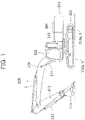
Fig. 1 is a side view of a hydraulic excavator equipped with a hydraulic control system of a construction machine according to a first embodiment of the present invention. -
Fig. 2 is a conceptual drawing illustrating a control/hydraulic circuit related to an arm cylinder in the hydraulic control system of the construction machine according to the first embodiment of the present invention. -
Fig. 3 is a functional block diagram illustrating the processing function of a controller constituting the hydraulic control system of the construction machine according to the first embodiment of the present invention. -
Fig. 4 is a characteristic chart illustrating the relationship between an arm angle and a load acting on an arm cylinder when crowding is performed on the arm in the air from an angle close to the horizontal direction with respect to the ground to the vertical direction in the hydraulic control system of the construction machine according to the first embodiment of the present invention. -
Fig. 5 is a characteristic chart illustrating the relationship between the arm angle and the target opening area of a meter-outrestrictor 23a when crowding is performed on the arm in the air from an angle close to the horizontal direction with respect to the ground to the vertical direction in the hydraulic control system of the construction machine according to the first embodiment of the present invention. -
Fig. 6 is a conceptual drawing illustrating a control/hydraulic circuit related to an arm cylinder in a hydraulic control system of a construction machine according to a second embodiment of the present invention. -
Fig. 7 is a characteristic chart illustrating the opening area characteristic of meter-out restrictors -
Fig. 8 is a functional block diagram illustrating the processing function of a controller constituting the hydraulic control system of the construction machine according to the second embodiment of the present invention. -
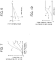
Fig. 9 is a characteristic chart illustrating the relationship between an arm angle and a load acting on an arm cylinder when crowding is performed on the arm in the air from an angle close to the horizontal direction with respect to the ground to the vertical direction in the hydraulic control system of the construction machine according to the second embodiment of the present invention. -
Fig. 10 is a characteristic chart illustrating the relationship between the arm angle and the target opening area of a meter-outrestrictor 52a when crowding is performed on the arm in the air from an angle close to the horizontal direction with respect to the ground to the vertical direction in the hydraulic control system of the construction machine according to the second embodiment of the present invention. - In the following, embodiments of the present invention will be described with reference to the drawings, taking a hydraulic excavator as an example of the construction machine.
-
Fig. 1 is a side view of a hydraulic excavator equipped with a hydraulic control system of a construction machine according to the first embodiment of the present invention. - In
Fig. 1 , ahydraulic excavator 301 is equipped with atrack structure 303 equipped with a pair of right andleft crawlers 302a and 302b, aswing structure 304 swingably provided above thetrack structure 303, and a multi-jointtype operation device 300 one end of which is connected to theswing structure 304. - Mounted on the
track structure 303 are trackhydraulic motors 318a and 318b driving thecrawlers 302a and 302b. At the central portion of theswing structure 304, there is provided a swinghydraulic motor 319 swinging theswing structure 304. On the front left side of theswing structure 304, there is installed anoperation room 305 accommodating an operation lever (operation device) 6 (SeeFig. 2 ). Theoperation device 300 is mounted to the front central portion of theswing structure 304. - The
operation device 300 is equipped with aboom 310 vertically swingably mounted to a boom foot provided at the front central portion of theswing structure 304, anarm 312 mounted to the distal end of theboom 310 so as to be swingable in the front-rear direction, and abucket 314 that is a work tool (attachment) mounted to the distal end of thearm 312 so as to be vertically rotatable. - Further, the
operation device 300 has a boom cylinder (hydraulic cylinder) 311 connected to the boom foot and theboom 310 and causing theboom 310 to swing in the vertical direction, an arm cylinder (hydraulic cylinder) 4 connected to theboom 310 and thearm 312 and causing thearm 312 to swing in the vertical direction, and a bucket cylinder (hydraulic cylinder) 315 connected to thearm 312 and thework tool 314 and causing thebucket 314 to rotate in the vertical direction. That is, theoperation device 300 is driven by thesehydraulic cylinders -
Fig. 2 is a conceptual drawing illustrating a control/hydraulic circuit related to the arm cylinder in the hydraulic control system of the construction machine according to the first embodiment of the present invention. InFig. 2 , the hydraulic control system according to the present embodiment is equipped with aprime mover 1, ahydraulic pump 2 driven by thisprime mover 1, avalve device 5 connected to adelivery line 3 of thehydraulic pump 2 and having anarm control valve 31 controlling the flow rate and direction of the hydraulic fluid supplied to thearm cylinder 4, and a pilot valve 6 that is an operation lever device for the arm. - The
hydraulic pump 2 is of the variable displacement type, and has a displacement volume varying member, e.g., aswash plate 2a, and theswash plate 2a is controlled by ahorsepower control actuator 2b so as to reduce the volume as the delivery pressure of thehydraulic pump 2 increases. - The
control valve 31 is of the center bypass type, and acenter bypass portion 21 is situated in acenter bypass line 32. The upstream side of thecenter bypass line 32 is connected to thedelivery line 3 of thehydraulic pump 2, and the downstream side thereof is connected to atank 33. Further, thecontrol valve 31 has apump port 31a, atank port 31b, andactuator ports pump port 31a is connected to thecenter bypass line 32. Thetank port 31b is connected to thetank 33, and theactuator ports arm cylinder 4 viaactuator lines - The pilot valve 6 has an
operation lever 36 and a pilotpressure generating portion 37 containing a pair of pressure reducing valves (not shown), and the pilotpressure generating portion 37 is connected to pilotpressure receiving portions control valve 31 viapilot lines operation lever 36 is operated, the designated pilotpressure generating portion 37 operates on of the pair of pressure reducing valves in accordance with the operating direction thereof, outputting a pilot pressure corresponding to the operation amount to one of thepilot lines - The
control valve 31 has a neutral position A and switching positions B and C, and when the pilot pressure is imparted to thepressure receiving portion 31e by thepilot line 38, switching is effected to the switching position B on the left-hand side as seen in the drawing. At this time, theactuator line 35 is on the meter-in side, and theactuator line 34 is on the meter-out side, and the hydraulic fluid is supplied to the bottom side hydraulic chamber of thearm cylinder 4, expanding the piston rod of thearm cylinder 4. - On the other hand, when the pilot pressure is imparted to the
pressure receiving portion 31f by thepilot line 39, switching is effected to the position C on the right-hand side as seen in the drawing. At this time, theactuator line 34 is on the meter-in side, and theactuator line 35 is on the meter-out side, and the hydraulic fluid is supplied to the rod side hydraulic chamber of thearm cylinder 4, contracting the piston rod of thearm cylinder 4. The expansion of the piston rod of thearm cylinder 4 corresponds to the arm drawing-in operation, that is, the crowding operation, and the contraction of the piston rod of thearm cylinder 4 corresponds to the arm pushing-out operation, that is, the damping operation. - Further, the
control valve 31 has meter-inrestrictors restrictors control valve 31 is at the switching position B, the flow rate of the hydraulic fluid supplied to thearm cylinder 4 is controlled by the meter-inrestrictor 22a, and the flow rate of the return hydraulic fluid from thearm cylinder 4 is controlled by the meter-outrestrictor 23a. On the other hand, when thecontrol valve 31 is at the switching position C, the flow rate of the hydraulic fluid supplied to thearm cylinder 4 is controlled by the meter-inrestrictor 22b, and the flow rate of the return hydraulic fluid from thearm cylinder 4 is controlled by the meter-outrestrictor 23b. - The hydraulic control system of the construction machine according to the first embodiment of the present invention is characterized in that it includes a
pressure sensor 41 detecting the pressure of the bottom side hydraulic chamber of thearm cylinder 4, apressure sensor 42 detecting the pressure of the rod side hydraulic chamber of thearm cylinder 4, apressure sensor 43 detecting an arm crowding pilot pressure output by the pilot valve 6, a solenoidproportional valve 44 arranged in thepilot line 38, and acontroller 45 inputting the detection signals of thepressure sensor 41, thepressure sensor 42, and thepressure sensor 43, performing predetermined computation processing, and outputting a command electric current to the solenoidproportional valve 44. - Next, the processing by the controller according to the present embodiment will be described with reference to
Fig. 3. Fig. 3 is a functional block diagram illustrating the processing function of the controller constituting the hydraulic control system of the construction machine according to the first embodiment of the present invention. - The
controller 45 is equipped with an arm cylinderload computation section 45a, a first meter-outopening computation section 45b, a second meter-outopening computation section 45c, a cylinder pressure sensorfailure detection section 45d, anoutput selection section 45e, and a solenoid electriccurrent computation section 45f. - The arm cylinder
load computation section 45a inputs the pressure signal of the bottom side hydraulic chamber of thearm cylinder 4 detected by thepressure sensor 41, and the pressure signal of the rod side hydraulic chamber of thearm cylinder 4 detected by thepressure sensor 42, and subtracts the product of the pressure signal of the rod side hydraulic chamber of thearm cylinder 4 and the pressure receiving area of the rod side hydraulic chamber from the product of the pressure signal of the bottom side hydraulic chamber of thearm cylinder 4 and the pressure receiving area of the bottom side hydraulic chamber, thereby calculating the load of thearm cylinder 4. - More specifically, there are provided: a first multiplier A1 inputting the pressure signal of the bottom side hydraulic chamber of the
arm cylinder 4 detected by thepressure sensor 41 as a first input, inputting a signal corresponding to the pressure receiving area of the bottom side hydraulic chamber as a second input, and outputting the result of the multiplication of the first input and the second input; a second multiplier A2 inputting the pressure signal of the rod side hydraulic chamber of thearm cylinder 4 detected by thepressure sensor 42 as a first input, inputting a signal corresponding to the pressure receiving area of the rod side hydraulic chamber as a second input, and outputting the result of the multiplication of the first input and the second input; and a subtracter B inputting the output signal of the first multiplier A1 as a first input, inputting the output signal of the second multiplier A2 as a second input, and outputting the result of the subtraction of the second input from the first input. The calculated load signal of thearm cylinder 4 is output to the first meter-outopening computation section 45b. - The arm cylinder
load computation section 45a operates such that, when, for example, a load in a direction opposite to the direction in which the piston rod of thearm cylinder 4 extends acts as in the case of excavating, the output of the first multiplier A1, which is the product of the pressure signal of the bottom side hydraulic chamber and the pressure receiving area of the bottom side hydraulic chamber, is larger than the output of the second multiplier A2, which is the product of the pressure signal of the rod side hydraulic chamber and the pressure receiving area of the rod side hydraulic chamber, and the output of the subtracter B, which is the result of the subtraction, is positive, with a positive load being calculated as the load of thearm cylinder 4. - On the other hand, when a load in the same direction as the direction in which the piston rod of the
arm cylinder 4 extends acts as in the case of the load due to the weight of the arm and attachment, the output of the first multiplier A1, which is the product of the pressure signal of the bottom side hydraulic chamber and the pressure receiving area of the bottom side hydraulic chamber, is smaller than the output of the second multiplier A2, which is the product of the pressure signal of the rod side hydraulic chamber and the pressure receiving area of the rod side hydraulic chamber, and the output of the subtracter B, which is the result of the subtraction, is negative, with a negative load being calculated as the load of thearm cylinder 4. - The first meter-out
opening computation section 45b inputs the arm crowding pilot pressure signal detected by thepressure sensor 43, and the load of thearm cylinder 4 calculated by the arm cylinderload computation section 45a, and calculates the target opening area of the meter-outrestrictor 23a in accordance with the load of thearm cylinder 4 and the arm crowding pilot pressure by using the table shown inFig. 3 . The calculated target opening area signal of the meter-outrestrictor 23a is output to theoutput selection section 45e. - In the table of the first meter-out
opening computation section 45b, the characteristic A indicated by the solid line indicates the characteristic (maximum value) of the target opening area signal of the meter-outrestrictor 23a in accordance with the arm crowding pilot pressure when the load signal of thearm cylinder 4 calculated by the arm cylinderload computation section 45a is positive. When the load signal is positive, this characteristic does not depend on the magnitude thereof. On the other hand, the characteristic B indicated by the dashed line indicates the characteristic (minimum value) of the target opening area signal of the meter-outrestrictor 23a in accordance with the arm crowding pilot pressure when the load signal of thearm cylinder 4 calculated by the arm cylinderload computation section 45a is negative and the absolute value thereof is maximum. When the arm crowding pilot pressure is the same, the characteristic B corresponds to the case where the load signal of thearm cylinder 4 is negative and where the absolute value is maximum. As the absolute value is reduced, there exists a characteristic line indicating an increase in the target opening area signal of the meter-outrestrictor 23a in the direction of the characteristic A. - In other words, under a fixed arm crowding pilot pressure, when the load signal of the
arm cylinder 4 is negative, and the absolute value is maximum, the target opening area signal of the meter-outrestrictor 23a is reduced to the minimum value. As the absolute value is reduced, the target opening area signal of the meter-outrestrictor 23a is increased in the direction of the characteristic A. - The second meter-out
opening computation section 45c inputs the arm crowding pilot pressure signal detected by thepressure sensor 43, and calculates the target opening area of the meter-outrestrictor 23a in accordance with the arm crowding pilot pressure by using the table shown inFig. 3 . The calculated target opening area signal of the meter-outrestrictor 23a is output to theoutput selection section 45e. Further, the characteristic in the table of the second meter-outopening computation section 45c is the same as the characteristic B of the first meter-outopening computation section 45b, and indicates the characteristic (minimum value) of the target opening area signal of the meter-outrestrictor 23a in accordance with the arm crowding pilot pressure. - The cylinder pressure sensor
failure detection section 45d inputs the pressure signal of the bottom side hydraulic chamber of thearm cylinder 4 detected by thepressure sensor 41, and the pressure signal of the rod side hydraulic chamber of thearm cylinder 4 detected by thepressure sensor 42, and compares the values of these pressure signals with the maximum threshold value and the minimum threshold value. When a condition in which the threshold value is exceeded has continued a fixed period of time, it determines that the cylinder pressure sensor is in a failure/an abnormal condition. For example, when disconnection of the circuit or contact failure of the connection portion arises, the output voltage of the sensor is a minimum voltage, and when the circuit is shortcircuited, it is to be expected that the output voltage of the sensor is a maximum voltage. Thus, when the threshold value is exceeded, and this condition continues for a fixed period of time, it is determined that the system is in a failure/an abnormal condition. - More specifically, there are provided a first comparator C1 which inputs as a first input the pressure signal of the bottom side hydraulic chamber of the
arm cylinder 4 detected by thepressure sensor 41 and which inputs the maximum threshold value as a second input, a second comparator C2 which is of the same first input as the first comparator C1 and which inputs the minimum threshold value as a second input, a third comparator C3 which inputs the pressure signal of the rod side hydraulic chamber of thearm cylinder 4 detected by thepressure sensor 42 as the first input and which inputs the maximum threshold value as the second input, a fourth comparator C4 which is of the same first input as the third comparator C3 and which inputs the minimum threshold value as the second input, a first time computing unit (timer) D1 which inputs the output signal of the first comparator A1, a second time computing unit (timer) D2 which inputs the output signal of the second comparator C2, a third time computing unit (timer) D3 which inputs the output signal of the third comparator C3, a fourth time computing unit (timer) D4 which inputs the output signal of the fourth comparator C4, and a logical sum computing unit E which inputs the output signals of the first through fourth time computing units D1 through D4. - Here, the first comparator C1 and the third comparator C3 output a
digital output signal 1 when the first input exceeds the second input, which is the threshold value. The second comparator C2 and the fourth comparator C4 output thedigital output signal 1 when the first input is less than the second input, which is the threshold value. The first through fourth time computing units D1 through D4 output thedigital output signal 1 after the elapse of a predetermined time after the input of the input signal. The logical sum computing unit E outputs thedigital output signal 1 when one of the four signals input is 1. The calculated digital output signal is output to theoutput selection section 45e. - The
output selection section 45e inputs the output signal of the first meter-outopening computation section 45b as the first input, and inputs the output signal of the second meter-outopening computation section 45c as the second input, inputting the digital output signal from the logical sum computing unit C of the cylinder pressure sensorfailure detection section 45d as a switching signal. When the digital output signal, which is the switching signal, is 1, theoutput selection section 45e outputs the output signal of the second meter-outopening computation section 45c, which is the second input, as the output signal. When the digital output signal from the logical sum computing unit E of the switching signal input is 0, it outputs the output signal of the first meter-outopening computation section 45b, which is the first input. The output signal of theoutput selection section 45e is input to a solenoid electriccurrent computation section 45f. - The solenoid electric
current computation section 45f inputs from theoutput selection section 45e the target opening area of the meter-outrestrictor 23a calculated by the first meter-outopening computation section 45b or the second meter-outopening computation section 45c, and calculates a solenoid electric current value in accordance with the input value, outputting it to the solenoidproportional valve 44 as a control signal. - Next, the operation of the hydraulic control system of the construction machine according to the first embodiment of the present invention will be described with reference to
Figs. 4 and 5. Fig. 4 is a characteristic chart illustrating the relationship between an arm angle and a load acting on the arm cylinder when crowding is performed on the arm in the air from an angle close to the horizontal direction with respect to the ground to the vertical direction in the hydraulic control system of the construction machine according to the first embodiment of the present invention, andFig. 5 is a characteristic chart illustrating the relationship between the arm angle and the target opening area of the meter-out restrictor when crowding is performed on the arm in the air from an angle close to the horizontal direction with respect to the ground to the vertical direction in the hydraulic control system of the construction machine according to the first embodiment of the present invention. - In the following description, the state in which the
pressure sensors pressure sensors - First, the operation in the case where the
pressure sensors Fig. 4 is the angle of anarm 312 with respect to the horizontal plane. Suppose that the state in which thearm 312 is maintained horizontal in the air with respect to the ground corresponds to 0 degrees, and that the state in which thearm 312 is maintained vertical with respect to the horizontal plane after the expansion of thearm cylinder 4 and the counterclockwise rotation inFig. 1 of thearm 312 corresponds to 90 degrees. - In
Fig. 4 , the characteristic A indicated by the solid line indicates the load of thearm cylinder 4 in the case where a standard bucket is attached, and the characteristic B indicated by the dashed line indicates the load of thearm cylinder 4 in the case where an attachment heavier than the standard bucket is attached. In both cases, in the state in which the arm angle is close to 0 degrees (horizontal), the load of the arm cylinder is a negative load due to the weight of thearm 312 and of the attachment, whereas as the arm angle approaches vertical, the absolute value of the negative load is reduced, and the load becomes positive at a position close to vertical. -
Fig. 5 shows the relationship between the arm angle at this time and the target opening area signal of the meter-outrestrictor 23a calculated by the first meter-outopening computation section 45b of thecontroller 45. InFig. 5 , the characteristic A indicated by the solid line indicates the target opening area of the meter-outrestrictor 23a in the case where the standard bucket is attached, and the characteristic B indicated by the dashed line indicates the target opening area of the meter-outrestrictor 23a in the case where an attachment heavier than the standard bucket is attached. - In the case where the standard bucket is attached, in the state in which the arm angle is close to 0 degrees (horizontal), the target opening area of the meter-out
restrictor 23a is restricted, whereas, as the arm angle approaches vertical, it increases, and attains a maximum value. Here, this maximum value corresponds to the opening area characteristic of the characteristic A indicated by the solid line of the first meter-outopening computation section 45b ofFig. 3 . - In the case where an attachment heavier than the standard bucket is attached, in the state in which the arm angle is close to 0 degrees (horizontal), the target opening area of the meter-out
restrictor 23a is the minimum value, whereas, as the arm angle approaches vertical, it increases, and attains a maximum value. Here, this minimum value corresponds to the opening area characteristic of the characteristic B indicated by the dashed line of the first meter-outopening computation section 45b ofFig. 3 . - In this way, in the present embodiment, the target opening area of the meter-out
restrictor 23a is varied in accordance with the load of thearm cylinder 4, so that it is possible to reduce the meter-out pressure loss, and it is also possible to reduce the energy loss. - Here, to facilitate the understanding of the present embodiment, a case will be described where, in the
controller 45 shown inFig. 3 , the second meter-outopening computation section 45c, the cylinder pressure sensorfailure detection section 45d, and theoutput selection section 45e are not provided, and where a failure or an abnormal condition has arisen in the pressure sensor. - For example, in the case where the output of the
pressure sensor 41 attains a maximum and fixed level independently of the actual detection pressure, the load signal of the arm cylinder calculated by the arm cylinderload computation section 45a shown inFig. 3 is always a positive load, so that the opening area characteristic of the characteristic A indicated by the solid line is output as the target opening area signal of the meter-outrestrictor 23a calculated by the first meter-outopening computation section 45b. - In this situation, when crowding is performed on the arm in the air from an angle close to horizontal with respect to the ground to vertical, a reduction is not effected to the requite opening area for the opening area of the meter-out restrictor 23a to support the negative load as shown in
Fig. 5 although a negative load is acting in the state in which the arm angle is actually close to 0 degrees (horizontal) as shown inFig. 4 . As a result, there is generated a breathing phenomenon, and there is a fear of deterioration in operability and damage of thearm cylinder 4 and thevalve device 5. The hydraulic control system of the construction machine of the present invention aims to prevent deterioration in operability and damage of the hydraulic apparatus even in such a failure/an abnormal condition of the pressure sensor. - A case will be described with reference to
Fig. 3 in which a failure or an abnormal condition has arisen in one or both of thepressure sensors - For example, in the case where the output of the
pressure sensor 41 has attained a maximum and fixed level independently of the actual detection pressure, the first input of the first comparator C1 of the cylinder pressure sensorfailure detection section 45d exceeds the second input, which is the maximum threshold value, so that thedigital output signal 1 is output, and is input to the first time computing unit D1. The first time computing unit D1 outputs the digital output signal to the logical sum computing unit E after the elapse of a predetermined period of time since the input of the input signal. Thedigital output signal 1 is output to theoutput selection section 45e from the logical sum computing unit E. - Since the
digital output signal 1, which is a switching signal, has been input, theoutput selection section 45e switches the output signal from the output signal of the first meter-outopening computation section 45b, which is the first input, to the output signal of the second meter-outopening computation section 45c, which is the second input. The output signal is then output to the solenoid electriccurrent computation section 45f, and the solenoid electriccurrent computation section 45f calculates a solenoid electric current value in accordance with the input value, and controls the solenoidproportional valve 44. - In the table of the second meter-out
opening computation section 45c, there is set the characteristic (minimum value) of the target opening area signal of the meter-outrestrictor 23a in accordance with the arm crowding pilot pressure that is the same as the characteristic B of the first meter-outopening computation section 45b, so that, even in the case of a condition in which the absolute value of the negative load acting on thearm cylinder 4 is maximum, for example, even when the arm to which a heavy attachment is attached assumes an attitude close to horizontal with respect to the ground, the opening area of the meter-outrestrictor 23a is reduced to the requisite opening area for supporting the negative load, so that no breathing phenomenon arises. - In this way, when a failure or an abnormal condition has arisen in one or both of the
pressure sensors restrictor 23a is controlled based on the operation amount of theoperation lever 36, so that it is possible to prevent deterioration in operability when a negative load acts on thearm cylinder 4. - In the hydraulic control system of the construction machine according to the first embodiment of the present invention, even when a failure or an abnormal condition arises in the
pressure sensors - In the following, a hydraulic control system of a construction machine according to the second embodiment of the present invention will be described with reference to the drawings.
Fig. 6 is a conceptual drawing illustrating a control/hydraulic circuit related to an arm cylinder in the hydraulic control system of the construction machine according to the second embodiment of the present invention, andFig. 7 is a characteristic chart illustrating the opening area characteristic of meter-outrestrictors Figs. 6 and7 , the same portions as those ofFigs. 1 through 5 are indicated by the same reference numerals, and a detailed description thereof will be left out. - In the hydraulic control system of the construction machine according to the second embodiment of the present invention, the system of the control/hydraulic circuit is roughly the same as that of the first embodiment, and it differs from the first embodiment in that the solenoid
proportional valve 44 arranged in thepilot line 38 is omitted, that there is provided a meter-out branching-off line 51 branching off from the meter-outside actuator line 34 at the time of the arm crowding request and connected to thetank 33, that a meter-outcontrol valve 52 is arranged in the meter-out branching-off line 51, and that there is provided a solenoidproportional valve 53 for effecting the switching of the spool position of the meter-outcontrol valve 52. - The meter-out
control valve 52 is a 2-port/2-position valve, and is equipped with a meter-outrestrictor 52a and a pressure receiving portion 52b. The pressure receiving portion 52b is connected to an arm crowding commandside pilot line 38 via asignal pressure line 54. A solenoidproportional valve 53 is arranged in thesignal pressure line 54. - The solenoid
proportional valve 53 reduces the arm crowding pilot pressure in accordance with a command electric current output from thecontroller 45, and outputs the signal pressure to the pressure receiving portion 52b. - In the first embodiment, a reduction in the meter-out pressure loss is effected by controlling the opening area of solely the meter-out
restrictor 23a in theflow control valve 31 in accordance with the magnitude of the negative load, whereas the main feature of the present embodiment lies in the fact that the reduction in the meter-out pressure loss is effected by controlling the sum total of the opening area of the meter-outrestrictor 23a in thecontrol valve 31 and the opening area of the meter-outrestrictor 52a in the meter-outcontrol valve 52 in accordance with the magnitude of the negative load. In the present embodiment, the sum total of the opening areas of the tworestrictors restrictor 52a in accordance with the magnitude of the negative load. -
Fig. 7 shows the opening area characteristics of the meter-outrestrictor 52a and the meter-outrestrictor 23a, that is, the relationship between the stroke (spool position) and the opening area of the meter-outcontrol valve 52 and thecontrol valve 31. In the drawing, the solid line A indicates the opening area characteristic of the meter-outrestrictor 52a when the arm crowding pilot pressure is imparted to the meter-outcontrol valve 52a, and the dashed line B indicates the opening area characteristic of the meter-outrestrictor 23a when the arm crowding pilot pressure is imparted to thecontrol valve 31. The dotted line C indicates the total opening area characteristic of the meter-outrestrictor 52a and the meter-outrestrictor 23a. - The hydraulic control system of the construction machine according to the second embodiment of the present invention has, as the characteristic construction thereof, the
pressure sensor 41 detecting the pressure of the bottom side hydraulic chamber of thearm cylinder 4, thepressure sensor 42 detecting the pressure of the rod side hydraulic chamber of thearm cylinder 4, thepressure sensor 43 detecting the arm crowding pilot pressure output from the pilot valve 6, the meter-outcontrol valve 52 arranged in the meter-out branching-off line 51, the solenoidproportional valve 53 effecting the switching of the spool position of the meter-outcontrol valve 52, and thecontroller 45 inputting the detection signals of thepressure sensor 41, thepressure sensor 42, and thepressure sensor 43, performing predetermined computation processing, and outputting a command electric current to the solenoidproportional valve 53. - Next, the processing by the controller according to the present embodiment will be described with reference to
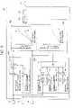
Fig. 8. Fig. 8 is a functional block diagram illustrating the processing function of a controller constituting the hydraulic control system of the construction machine according to the second embodiment of the present invention. InFig. 8 , the portions that are the same as those ofFigs. 1 through 7 are indicated by the same reference numerals, and a detailed description thereof will be left out. - The
controller 45 is equipped with an arm cylinderload computation section 45a, a third meter-outopening computation section 45g, a fourth meter-outopening computation section 45h, a cylinder pressure sensorfailure detection section 45d, anoutput selection section 45e, and a solenoid electriccurrent computation section 45f. The arm cylinderload computation section 45a, the cylinder pressure sensorfailure detection section 45d, theoutput selection section 45e, and the solenoid electriccurrent computation section 45f are the same as those of the first embodiment, so a description thereof will be left out. The third meter-outopening computation section 45g and the fourth meter-outopening computation section 45h differ from those of the first embodiment solely in the table setting thereof. - In the table of the third meter-out
opening computation section 45g, there is set a characteristic increasing the target opening area of the meter-out restrictor 52a as the arm crowding pilot pressure is increased, and the characteristic A indicated by the solid line indicates the characteristic (maximum value) of the target opening area signal of the meter-outrestrictor 52a in accordance with the arm crowding pilot pressure when the load signal of thearm cylinder 4 calculated by the arm cylinderload computation section 45a is positive. When the load signal is positive, this characteristic does not depend on the magnitude thereof. On the other hand, the characteristic B indicated by the dashed line indicates the characteristic (minimum value) of the target opening area signal of the meter-outrestrictor 52a in accordance with the arm crowding pilot pressure when the load signal of thearm cylinder 4 calculated by the arm cylinderload computation section 45a is negative and the absolute value thereof is maximum. - In the table of the fourth meter-out
opening computation section 45h, there is set a characteristic increasing the target opening area of the meter-out restrictor 52a as the arm crowding pilot pressure is increased, and the characteristic of this table is the same as the characteristic B of the third meter-outopening computation section 45g, and indicates the characteristic (minimum value) of the target opening area signal of the meter-outrestrictor 52a in accordance with the arm crowding pilot pressure. - Next, the operation of the hydraulic control system of the construction machine according to the second embodiment of the present invention will be described with reference to
Figs. 9 and 10. Fig. 9 is a characteristic chart illustrating the relationship between an arm angle and a load acting on an arm cylinder when crowding is performed on the arm in the air from an angle close to the horizontal direction with respect to the ground to the vertical direction in the hydraulic control system of the construction machine according to the second embodiment of the present invention, andFig. 10 is a characteristic chart illustrating the relationship between the arm angle and the target opening area of the meter-outrestrictor 52a when crowding is performed on the arm in the air from an angle close to the horizontal direction with respect to the ground to the vertical direction in the hydraulic control system of the construction machine according to the second embodiment of the present invention. - First, the operation in the case where the
pressure sensors pressure sensors output selection section 45e from the cylinder pressure sensorfailure detection section 45d, so that the target opening area calculated by the third meter-outopening computation section 45g is output from theoutput selection section 45e to the solenoid electriccurrent computation section 45f, and the solenoid electriccurrent computation section 45f calculates the solenoid electric current value in accordance with the input value to control the solenoidproportional valve 53. - In
Fig. 9 , the characteristic A indicated by the solid line indicates the load of thearm cylinder 4 in the case where a standard bucket is attached, and the characteristic B indicated by the dashed line indicates the load of thearm cylinder 4 in the case where an attachment heavier than the standard bucket is attached. In both cases, in the state in which the arm angle is close to 0 degrees (horizontal), the load of the arm cylinder is a negative load due to the weight of thearm 312 and of the attachment. As the arm angle approaches vertical, the absolute value of the negative load is reduced, and the load becomes positive at an angle close to vertical. -
Fig. 10 shows the relationship between the arm angle at this time and the target opening area signal of the meter-outrestrictor 52a calculated by the third meter-outopening computation section 45g of thecontroller 45. InFig. 10 , the characteristic A indicated by the solid line indicates the target opening area of the meter-outrestrictor 52a in the case where the standard bucket is attached, and the characteristic B indicated by the dashed line indicates the target opening area of the meter-outrestrictor 52a in the case where an attachment heavier than the standard bucket is attached. - In the case where the standard bucket is attached, in the state in which the arm angle is close to 0 degrees (horizontal), the target opening area of the meter-out
restrictor 52a is restricted, whereas, as the arm angle approaches vertical, it increases, and attains a maximum value. In the case where an attachment heavier than the standard bucket is attached, in the state in which the arm angle is close to 0 degrees (horizontal), the target opening area of the meter-outrestrictor 52a is minimum, whereas, as the arm angle approaches vertical, it increases, and attains a maximum value. Based on the above, the sum total of the opening areas of the meter-outrestrictors Fig. 7 . - In this way, in the present embodiment, the sum total of the opening areas of the meter-out
restrictors arm cylinder 4, so that, as in the first embodiment, it is possible to reduce the meter-out pressure loss, and also to reduce the energy loss. - Next, the case where a failure or an abnormal condition has arisen in one or both of the
pressure sensors - When the
pressure sensor output selection section 45e from the cylinder pressure sensorfailure detection section 45d, and the target opening area calculated by the fourth meter-outopening computation section 45h is output from theoutput selection section 45e to the solenoid electriccurrent computation section 45f, with the solenoid electriccurrent computation section 45f calculating a solenoid electric current value in accordance with the input value to control the solenoidproportional valve 53. - In the table of the fourth meter-out
opening computation section 45h, there is set the characteristic (minimum value) of the target opening area signal of the meter-outrestrictor 52a in accordance with the arm crowding pilot pressure which is the same as the characteristic B of the third meter-outopening computation section 45g, so that even under a condition in which the absolute value of the negative load acting on thearm cylinder 4 is maximum, for example, even when the arm to which a heavy attachment is attached assumes an attitude close to horizontal with respect to the ground, the opening area of the meter-outrestrictor 52a is reduced to the requisite opening area for supporting a negative load, so that no breathing phenomenon arises. - In this way, when a failure or an abnormal condition arises in one or both of the
pressure sensors restrictor 52a is controlled based on the operation amount of theoperation lever 36, so that it is possible to prevent deterioration in operability when a negative load acts on thearm cylinder 4. - In the hydraulic control system of the construction machine according to the second embodiment of the present invention described above, it is possible to attain the same effect as that of the first embodiment described above.
- While in the above-described embodiments the present invention is applied to the valve device of the
arm cylinder 4 of a hydraulic excavator, this should not be construed restrictively. For example, the same problem is involved in the bucket crowding operation of a hydraulic excavator, and the present invention may be applied to the valve device of the bucket cylinder. In this case, for example, in the hydraulic circuit shown inFigs. 2 and6 , thearm cylinder 4 is replaced by a bucket cylinder, thecontrol valve 31 for the arm is replaced by a control valve for the bucket, and the operation lever device 6 for the arm is replaced by an operation lever device for the bucket. - Further, so long as various negative loads, large and small, act on the hydraulic actuator, the present invention is also applicable to the valve device of a hydraulic actuator other than the arm cylinder or the bucket cylinder of a hydraulic excavator, or to the valve device of a hydraulic actuator of a construction machine other than the hydraulic excavator (e.g., a wheel loader or a crane).
- Further, the present invention is not restricted to the above-described embodiments but includes various modifications without departing from the scope of the invention as defined by the claims. For example, the present invention is not restricted to a system equipped with all the components described in connection with the above embodiments but includes a system in which part of the components are omitted. Further, part of the components related to a certain embodiment may be added to or replace the components related to another embodiment.
-
- 1: Prime mover
- 2: Hydraulic pump
- 2a: Displacement volume varying member (swash plate)
- 2b: Horsepower control actuator
- 3: Delivery line
- 4: Arm cylinder
- 5: Valve device
- 6: Pilot valve
- 21: Center bypass portion
- 22a: Meter-in restrictor
- 22b: Meter-in restrictor
- 23a: Meter-out restrictor
- 23b: Meter-out restrictor
- 31: Control valve
- 31e, 31f: Pressure receiving portion
- 32: Center bypass line
- 33: Tank
- 34, 35: Actuator line
- 36: Operation lever
- 37: Pilot pressure generating portion
- 38, 39: Pilot line
- 41: Pressure sensor
- 42: Pressure sensor
- 43: Pressure sensor
- 44: Solenoid proportional valve
- 45: Controller
- 45a: Arm cylinder load computation section
- 45b: First meter-out opening computation section
- 45c: Second meter-out opening computation section
- 45d: Cylinder pressure sensor failure detection section
- 45e: Output selection section
- 45f: Solenoid electric current computation section
- 45g: Third meter-out opening computation section
- 45h: Fourth meter-out opening computation section
- 51: Branching-off line
- 52: Meter-out control valve
- 52a: Meter-out restrictor
- 52b: Pressure receiving portion
- 53: Solenoid proportional valve
- 54: Signal pressure line
- 300: Operation device
- 312: Arm
- 314: Bucket (attachment)
- 315: Bucket cylinder
Claims (4)
- A construction machine comprising:a hydraulic actuator (4, 315) driven by a hydraulic fluid delivered from a hydraulic pump (2);a control valve (31) controlling a supply and discharge of the hydraulic fluid with respect to the hydraulic actuator (4, 315) in accordance with a spool position of the control valve (31);at least one meter-out flow line through which the hydraulic fluid discharged from the hydraulic actuator (4, 315) flows; wherein the at least one meter-out flow line is a first flow line through which the hydraulic fluid discharged from the hydraulic actuator (4, 315) flows when the hydraulic actuator (4, 315) operates in the same direction as a load applied to the hydraulic actuator (4,315) by an external force, the first flow line passing through the control valve (31);at least one variable restrictor (23a, 52a) provided in the at least one meter-out flow line; wherein the at least one variable restrictor (23a, 52a) is a first variable restrictor (23a) provided in the control valve (31) in the first flow line;an operation device (36) outputting an operation command signal for the hydraulic actuator (4, 315) in accordance with an operation amount;an operation amount sensor (43) detecting an operation amount of the operation device (36);a first pressure sensor detecting a pressure of at least one meter-in flow line;a second pressure sensor detecting a pressure of the at least one meter-out flow line;characterized in that the construction machine further comprisesa control device (45) includinga load calculating unit (45a) calculating a magnitude of a negative load which is a load applied to the hydraulic actuator (4,315) by an external force and which is a load in the same direction as an operating direction of the hydraulic actuator (4. 315) based on a detection result of the first pressure sensor and the second pressure sensor;a load abnormality detection unit (45d) detecting a failure or an abnormal condition of the first pressure sensor and the second pressure sensor; whereinthe control device (45) reduces an opening area of a sum total of the opening areas of the at least one variable restrictor (23a, 52a) provided in the at least one meter-out flow line in accordance with an increase in the magnitude of a negative load detected by the load calculation unit (45a) and the operation amount detected by the operation amount sensor (43), when the load abnormality detection unit (45d) does not detect a failure or an abnormal condition of the first pressure sensor or the second pressure sensor, andreduces the opening area of the sum total of the opening areas of the at least one variable restrictor (23a, 52a) to a predetermined value in accordance with the operation amount detected by the operation amount sensor (43), when the load abnormality detection unit (45d) detects a failure or an abnormal condition of at least one of the first pressure sensor and the second pressure sensor;the control device (45) reduces the opening area of the first variable restrictor (23a) by changing the spool position of the control valve (31) in accordance with an increase in the magnitude of the negative load detected by the load calculation unit (45a) and with an operation amount detected by the operation amount sensor (43) .
- The construction machine according to claim 1,wherein the at least one meter-out flow line includes the first flow line and a second flow line through which the hydraulic fluid discharged from the hydraulic actuator (4, 315) flows when the hydraulic actuator (4, 315) operates in the same direction as the negative load;the at least one variable restrictor (23a, 52a) include the first variable restrictor (23a) provided in the control valve in the first flow line and increasing in opening area with an increase in the operation amount of the operation device (36), and a second variable restrictor (52a) provided in the second flow line and increasing in opening area with an increase in a pilot pressure output from a hydraulic fluid source; andthe control device (45) reduces the sum total of the opening areas of the first variable restrictor (23a) and the second variable restrictor (52a) by reducing the opening area of the second variable restrictor (52a) in accordance with an increase in the magnitude of the negative load detected by the load calculation unit (45a) and with the operation amount detected by the operation amount sensor (43).
- The construction machine according to claim 1 or 2,wherein there exist an upper limit value and a lower limit value for each operation amount of the operation device (36) in a range in which the opening area of the at least one variable restrictor is varied in accordance with an increase in the magnitude of the negative load calculated by the load calculation unit (45a); andwhen the load abnormality detecting unit (45d) detects a failure or an abnormal condition of at least one of the first pressure sensor and the second pressure sensor, the opening area of the sum total of the opening areas of the at least one variable restrictor (23a, 52a) is reduced to the lower limit value existing for each operation amount of the operation device (36).
- The construction machine according to claim 1, wherein the hydraulic actuator (4, 315) is an arm cylinder (4) driving an arm (312) of a hydraulic excavator (301), or a bucket cylinder (315) driving a bucket (314).
Applications Claiming Priority (2)
| Application Number | Priority Date | Filing Date | Title |
|---|---|---|---|
| JP2015111733A JP6324347B2 (en) | 2015-06-01 | 2015-06-01 | Hydraulic control equipment for construction machinery |
| PCT/JP2016/065643 WO2016194783A1 (en) | 2015-06-01 | 2016-05-26 | Construction-machine hydraulic control device |
Publications (3)
| Publication Number | Publication Date |
|---|---|
| EP3306112A1 EP3306112A1 (en) | 2018-04-11 |
| EP3306112A4 EP3306112A4 (en) | 2019-03-20 |
| EP3306112B1 true EP3306112B1 (en) | 2022-09-21 |
Family
ID=57441192
Family Applications (1)
| Application Number | Title | Priority Date | Filing Date |
|---|---|---|---|
| EP16803218.3A Active EP3306112B1 (en) | 2015-06-01 | 2016-05-26 | Construction-machine hydraulic control device |
Country Status (6)
| Country | Link |
|---|---|
| US (1) | US10472804B2 (en) |
| EP (1) | EP3306112B1 (en) |
| JP (1) | JP6324347B2 (en) |
| KR (1) | KR101918434B1 (en) |
| CN (1) | CN107208672B (en) |
| WO (1) | WO2016194783A1 (en) |
Families Citing this family (13)
| Publication number | Priority date | Publication date | Assignee | Title |
|---|---|---|---|---|
| WO2017168686A1 (en) * | 2016-03-31 | 2017-10-05 | 日立建機株式会社 | Drive control device of construction machine |
| JP6693842B2 (en) * | 2016-09-08 | 2020-05-13 | 住友重機械建機クレーン株式会社 | crane |
| KR102078224B1 (en) * | 2017-03-27 | 2020-02-17 | 히다치 겡키 가부시키 가이샤 | Hydraulic control system of working machine |
| JP6707053B2 (en) * | 2017-03-29 | 2020-06-10 | 日立建機株式会社 | Work machine |
| JP6707064B2 (en) * | 2017-08-24 | 2020-06-10 | 日立建機株式会社 | Hydraulic work machine |
| JP6836480B2 (en) * | 2017-08-28 | 2021-03-03 | 株式会社神戸製鋼所 | Control method of flood control system, rubber kneader and flood control system |
| JP6947711B2 (en) * | 2018-09-28 | 2021-10-13 | 日立建機株式会社 | Construction machinery |
| CN109594607B (en) * | 2018-12-17 | 2022-01-21 | 潍柴动力股份有限公司 | Excavator walking hydraulic pump fault detection method and excavator |
| EP3699437A1 (en) * | 2019-02-25 | 2020-08-26 | Siemens Gamesa Renewable Energy A/S | Flow control for an actuator |
| JP7046024B2 (en) | 2019-02-26 | 2022-04-01 | 日立建機株式会社 | Work machine |
| KR102506272B1 (en) | 2020-12-18 | 2023-03-06 | 주식회사 씨앤비랩 | Semi-permanent makeup treatment device |
| US11654815B2 (en) | 2021-02-01 | 2023-05-23 | Caterpillar Inc. | Closed center hoist valve with snubbing |
| GB2604608A (en) * | 2021-03-08 | 2022-09-14 | Bamford Excavators Ltd | Hydraulic system |
Family Cites Families (13)
| Publication number | Priority date | Publication date | Assignee | Title |
|---|---|---|---|---|
| GB9503854D0 (en) * | 1995-02-25 | 1995-04-19 | Ultra Hydraulics Ltd | Electrohydraulic proportional control valve assemblies |
| JP3740259B2 (en) * | 1997-09-24 | 2006-02-01 | 株式会社アイチコーポレーション | Operating device |
| JP3901058B2 (en) * | 2002-08-21 | 2007-04-04 | コベルコ建機株式会社 | Hydraulic cylinder controller for construction machinery |
| JP2006177402A (en) | 2004-12-21 | 2006-07-06 | Sumitomo (Shi) Construction Machinery Manufacturing Co Ltd | Hydraulic circuit of construction machinery |
| US8291925B2 (en) | 2009-10-13 | 2012-10-23 | Eaton Corporation | Method for operating a hydraulic actuation power system experiencing pressure sensor faults |
| JP5388787B2 (en) * | 2009-10-15 | 2014-01-15 | 日立建機株式会社 | Hydraulic system of work machine |
| WO2012118564A2 (en) * | 2011-03-03 | 2012-09-07 | Eaton Corporation | Fault detection, isolation and reconfiguration systems and methods for controlling electrohydraulic systems used in construction equipment |
| JP2014029180A (en) * | 2012-07-31 | 2014-02-13 | Hitachi Constr Mach Co Ltd | Hydraulic control device of working machine |
| US9423800B2 (en) * | 2012-12-26 | 2016-08-23 | Eaton Corporation | Fail operational modes for an electro-hydraulic system |
| CN103397679B (en) * | 2013-07-31 | 2015-12-02 | 南京工业大学 | A kind of swing arm energy-saving control system |
| JP6291360B2 (en) * | 2014-06-11 | 2018-03-14 | 株式会社神戸製鋼所 | Hydraulic drive device for work machine |
| JP6250515B2 (en) * | 2014-10-07 | 2017-12-20 | 日立建機株式会社 | Hydraulic control equipment for construction machinery |
| JP6474718B2 (en) * | 2015-12-25 | 2019-02-27 | 日立建機株式会社 | Hydraulic control equipment for construction machinery |
-
2015
- 2015-06-01 JP JP2015111733A patent/JP6324347B2/en active Active
-
2016
- 2016-05-26 WO PCT/JP2016/065643 patent/WO2016194783A1/en active Application Filing
- 2016-05-26 EP EP16803218.3A patent/EP3306112B1/en active Active
- 2016-05-26 KR KR1020177021319A patent/KR101918434B1/en active IP Right Grant
- 2016-05-26 US US15/554,533 patent/US10472804B2/en active Active
- 2016-05-26 CN CN201680008255.XA patent/CN107208672B/en active Active
Also Published As
| Publication number | Publication date |
|---|---|
| US20180051444A1 (en) | 2018-02-22 |
| US10472804B2 (en) | 2019-11-12 |
| KR101918434B1 (en) | 2018-11-13 |
| EP3306112A4 (en) | 2019-03-20 |
| WO2016194783A1 (en) | 2016-12-08 |
| KR20180004703A (en) | 2018-01-12 |
| JP6324347B2 (en) | 2018-05-16 |
| EP3306112A1 (en) | 2018-04-11 |
| CN107208672A (en) | 2017-09-26 |
| CN107208672B (en) | 2018-11-09 |
| JP2016223563A (en) | 2016-12-28 |
Similar Documents
| Publication | Publication Date | Title |
|---|---|---|
| EP3306112B1 (en) | Construction-machine hydraulic control device | |
| EP2716919B1 (en) | Rotary work machine | |
| KR101887318B1 (en) | Hydraulic drive system of industrial machine | |
| KR101973872B1 (en) | Hydraulic drive system for work machine | |
| CN107949706B (en) | Working machine | |
| JP5886976B2 (en) | Work machine | |
| US20140150416A1 (en) | Hydraulic actuator damping control system for construction machinery | |
| JP6250515B2 (en) | Hydraulic control equipment for construction machinery | |
| WO2014010222A1 (en) | Tilt angle control device | |
| US20130125537A1 (en) | Swirl flow control system for construction equipment and method of controlling the same | |
| US10829908B2 (en) | Construction machine | |
| US20150204359A1 (en) | Construction machine | |
| WO2015151776A1 (en) | Oil pressure control device for work machine | |
| JP6591370B2 (en) | Hydraulic control equipment for construction machinery | |
| KR102054519B1 (en) | Hydraulic system of construction machinery | |
| JP2930847B2 (en) | Hydraulic drive for construction machinery | |
| JP2014105541A (en) | Work machine |
Legal Events
| Date | Code | Title | Description |
|---|---|---|---|
| STAA | Information on the status of an ep patent application or granted ep patent |
Free format text: STATUS: THE INTERNATIONAL PUBLICATION HAS BEEN MADE |
|
| PUAI | Public reference made under article 153(3) epc to a published international application that has entered the european phase |
Free format text: ORIGINAL CODE: 0009012 |
|
| STAA | Information on the status of an ep patent application or granted ep patent |
Free format text: STATUS: REQUEST FOR EXAMINATION WAS MADE |
|
| 17P | Request for examination filed |
Effective date: 20180102 |
|
| AK | Designated contracting states |
Kind code of ref document: A1 Designated state(s): AL AT BE BG CH CY CZ DE DK EE ES FI FR GB GR HR HU IE IS IT LI LT LU LV MC MK MT NL NO PL PT RO RS SE SI SK SM TR |
|
| AX | Request for extension of the european patent |
Extension state: BA ME |
|
| DAV | Request for validation of the european patent (deleted) | ||
| DAX | Request for extension of the european patent (deleted) | ||
| A4 | Supplementary search report drawn up and despatched |
Effective date: 20190218 |
|
| RIC1 | Information provided on ipc code assigned before grant |
Ipc: F15B 11/08 20060101ALI20190212BHEP Ipc: F15B 20/00 20060101AFI20190212BHEP Ipc: F15B 11/04 20060101ALI20190212BHEP Ipc: E02F 9/22 20060101ALI20190212BHEP |
|
| REG | Reference to a national code |
Ref country code: DE Ref legal event code: R079 Ref document number: 602016075175 Country of ref document: DE Free format text: PREVIOUS MAIN CLASS: F15B0020000000 Ipc: E02F0009260000 |
|
| GRAP | Despatch of communication of intention to grant a patent |
Free format text: ORIGINAL CODE: EPIDOSNIGR1 |
|
| STAA | Information on the status of an ep patent application or granted ep patent |
Free format text: STATUS: GRANT OF PATENT IS INTENDED |
|
| RIC1 | Information provided on ipc code assigned before grant |
Ipc: E02F 9/22 20060101ALI20220504BHEP Ipc: F15B 11/044 20060101ALI20220504BHEP Ipc: E02F 9/26 20060101AFI20220504BHEP |
|
| INTG | Intention to grant announced |
Effective date: 20220524 |
|
| GRAS | Grant fee paid |
Free format text: ORIGINAL CODE: EPIDOSNIGR3 |
|
| GRAA | (expected) grant |
Free format text: ORIGINAL CODE: 0009210 |
|
| STAA | Information on the status of an ep patent application or granted ep patent |
Free format text: STATUS: THE PATENT HAS BEEN GRANTED |
|
| AK | Designated contracting states |
Kind code of ref document: B1 Designated state(s): AL AT BE BG CH CY CZ DE DK EE ES FI FR GB GR HR HU IE IS IT LI LT LU LV MC MK MT NL NO PL PT RO RS SE SI SK SM TR |
|
| REG | Reference to a national code |
Ref country code: GB Ref legal event code: FG4D |
|
| REG | Reference to a national code |
Ref country code: CH Ref legal event code: EP |
|
| REG | Reference to a national code |
Ref country code: IE Ref legal event code: FG4D |
|
| REG | Reference to a national code |
Ref country code: DE Ref legal event code: R096 Ref document number: 602016075175 Country of ref document: DE |
|
| REG | Reference to a national code |
Ref country code: AT Ref legal event code: REF Ref document number: 1520021 Country of ref document: AT Kind code of ref document: T Effective date: 20221015 |
|
| REG | Reference to a national code |
Ref country code: LT Ref legal event code: MG9D |
|
| REG | Reference to a national code |
Ref country code: NL Ref legal event code: MP Effective date: 20220921 |
|
| PG25 | Lapsed in a contracting state [announced via postgrant information from national office to epo] |
Ref country code: SE Free format text: LAPSE BECAUSE OF FAILURE TO SUBMIT A TRANSLATION OF THE DESCRIPTION OR TO PAY THE FEE WITHIN THE PRESCRIBED TIME-LIMIT Effective date: 20220921 Ref country code: RS Free format text: LAPSE BECAUSE OF FAILURE TO SUBMIT A TRANSLATION OF THE DESCRIPTION OR TO PAY THE FEE WITHIN THE PRESCRIBED TIME-LIMIT Effective date: 20220921 Ref country code: NO Free format text: LAPSE BECAUSE OF FAILURE TO SUBMIT A TRANSLATION OF THE DESCRIPTION OR TO PAY THE FEE WITHIN THE PRESCRIBED TIME-LIMIT Effective date: 20221221 Ref country code: LV Free format text: LAPSE BECAUSE OF FAILURE TO SUBMIT A TRANSLATION OF THE DESCRIPTION OR TO PAY THE FEE WITHIN THE PRESCRIBED TIME-LIMIT Effective date: 20220921 Ref country code: LT Free format text: LAPSE BECAUSE OF FAILURE TO SUBMIT A TRANSLATION OF THE DESCRIPTION OR TO PAY THE FEE WITHIN THE PRESCRIBED TIME-LIMIT Effective date: 20220921 Ref country code: FI Free format text: LAPSE BECAUSE OF FAILURE TO SUBMIT A TRANSLATION OF THE DESCRIPTION OR TO PAY THE FEE WITHIN THE PRESCRIBED TIME-LIMIT Effective date: 20220921 |
|
| REG | Reference to a national code |
Ref country code: AT Ref legal event code: MK05 Ref document number: 1520021 Country of ref document: AT Kind code of ref document: T Effective date: 20220921 |
|
| PG25 | Lapsed in a contracting state [announced via postgrant information from national office to epo] |
Ref country code: HR Free format text: LAPSE BECAUSE OF FAILURE TO SUBMIT A TRANSLATION OF THE DESCRIPTION OR TO PAY THE FEE WITHIN THE PRESCRIBED TIME-LIMIT Effective date: 20220921 Ref country code: GR Free format text: LAPSE BECAUSE OF FAILURE TO SUBMIT A TRANSLATION OF THE DESCRIPTION OR TO PAY THE FEE WITHIN THE PRESCRIBED TIME-LIMIT Effective date: 20221222 |
|
| PG25 | Lapsed in a contracting state [announced via postgrant information from national office to epo] |
Ref country code: SM Free format text: LAPSE BECAUSE OF FAILURE TO SUBMIT A TRANSLATION OF THE DESCRIPTION OR TO PAY THE FEE WITHIN THE PRESCRIBED TIME-LIMIT Effective date: 20220921 Ref country code: RO Free format text: LAPSE BECAUSE OF FAILURE TO SUBMIT A TRANSLATION OF THE DESCRIPTION OR TO PAY THE FEE WITHIN THE PRESCRIBED TIME-LIMIT Effective date: 20220921 Ref country code: PT Free format text: LAPSE BECAUSE OF FAILURE TO SUBMIT A TRANSLATION OF THE DESCRIPTION OR TO PAY THE FEE WITHIN THE PRESCRIBED TIME-LIMIT Effective date: 20230123 Ref country code: ES Free format text: LAPSE BECAUSE OF FAILURE TO SUBMIT A TRANSLATION OF THE DESCRIPTION OR TO PAY THE FEE WITHIN THE PRESCRIBED TIME-LIMIT Effective date: 20220921 Ref country code: CZ Free format text: LAPSE BECAUSE OF FAILURE TO SUBMIT A TRANSLATION OF THE DESCRIPTION OR TO PAY THE FEE WITHIN THE PRESCRIBED TIME-LIMIT Effective date: 20220921 Ref country code: AT Free format text: LAPSE BECAUSE OF FAILURE TO SUBMIT A TRANSLATION OF THE DESCRIPTION OR TO PAY THE FEE WITHIN THE PRESCRIBED TIME-LIMIT Effective date: 20220921 |
|
| PG25 | Lapsed in a contracting state [announced via postgrant information from national office to epo] |
Ref country code: SK Free format text: LAPSE BECAUSE OF FAILURE TO SUBMIT A TRANSLATION OF THE DESCRIPTION OR TO PAY THE FEE WITHIN THE PRESCRIBED TIME-LIMIT Effective date: 20220921 Ref country code: PL Free format text: LAPSE BECAUSE OF FAILURE TO SUBMIT A TRANSLATION OF THE DESCRIPTION OR TO PAY THE FEE WITHIN THE PRESCRIBED TIME-LIMIT Effective date: 20220921 Ref country code: IS Free format text: LAPSE BECAUSE OF FAILURE TO SUBMIT A TRANSLATION OF THE DESCRIPTION OR TO PAY THE FEE WITHIN THE PRESCRIBED TIME-LIMIT Effective date: 20230121 Ref country code: EE Free format text: LAPSE BECAUSE OF FAILURE TO SUBMIT A TRANSLATION OF THE DESCRIPTION OR TO PAY THE FEE WITHIN THE PRESCRIBED TIME-LIMIT Effective date: 20220921 |
|
| REG | Reference to a national code |
Ref country code: DE Ref legal event code: R097 Ref document number: 602016075175 Country of ref document: DE |
|
| PG25 | Lapsed in a contracting state [announced via postgrant information from national office to epo] |
Ref country code: NL Free format text: LAPSE BECAUSE OF FAILURE TO SUBMIT A TRANSLATION OF THE DESCRIPTION OR TO PAY THE FEE WITHIN THE PRESCRIBED TIME-LIMIT Effective date: 20220921 Ref country code: AL Free format text: LAPSE BECAUSE OF FAILURE TO SUBMIT A TRANSLATION OF THE DESCRIPTION OR TO PAY THE FEE WITHIN THE PRESCRIBED TIME-LIMIT Effective date: 20220921 |
|
| PLBE | No opposition filed within time limit |
Free format text: ORIGINAL CODE: 0009261 |
|
| STAA | Information on the status of an ep patent application or granted ep patent |
Free format text: STATUS: NO OPPOSITION FILED WITHIN TIME LIMIT |
|
| PG25 | Lapsed in a contracting state [announced via postgrant information from national office to epo] |
Ref country code: DK Free format text: LAPSE BECAUSE OF FAILURE TO SUBMIT A TRANSLATION OF THE DESCRIPTION OR TO PAY THE FEE WITHIN THE PRESCRIBED TIME-LIMIT Effective date: 20220921 |
|
| PGFP | Annual fee paid to national office [announced via postgrant information from national office to epo] |
Ref country code: DE Payment date: 20230331 Year of fee payment: 8 |
|
| 26N | No opposition filed |
Effective date: 20230622 |
|
| PG25 | Lapsed in a contracting state [announced via postgrant information from national office to epo] |
Ref country code: SI Free format text: LAPSE BECAUSE OF FAILURE TO SUBMIT A TRANSLATION OF THE DESCRIPTION OR TO PAY THE FEE WITHIN THE PRESCRIBED TIME-LIMIT Effective date: 20220921 |
|
| PGFP | Annual fee paid to national office [announced via postgrant information from national office to epo] |
Ref country code: GB Payment date: 20230406 Year of fee payment: 8 |
|
| REG | Reference to a national code |
Ref country code: CH Ref legal event code: PL |
|
| PG25 | Lapsed in a contracting state [announced via postgrant information from national office to epo] |
Ref country code: MC Free format text: LAPSE BECAUSE OF FAILURE TO SUBMIT A TRANSLATION OF THE DESCRIPTION OR TO PAY THE FEE WITHIN THE PRESCRIBED TIME-LIMIT Effective date: 20220921 |
|
| REG | Reference to a national code |
Ref country code: BE Ref legal event code: MM Effective date: 20230531 |
|
| PG25 | Lapsed in a contracting state [announced via postgrant information from national office to epo] |
Ref country code: MC Free format text: LAPSE BECAUSE OF FAILURE TO SUBMIT A TRANSLATION OF THE DESCRIPTION OR TO PAY THE FEE WITHIN THE PRESCRIBED TIME-LIMIT Effective date: 20220921 Ref country code: LU Free format text: LAPSE BECAUSE OF NON-PAYMENT OF DUE FEES Effective date: 20230526 Ref country code: LI Free format text: LAPSE BECAUSE OF NON-PAYMENT OF DUE FEES Effective date: 20230531 Ref country code: CH Free format text: LAPSE BECAUSE OF NON-PAYMENT OF DUE FEES Effective date: 20230531 |
|
| REG | Reference to a national code |
Ref country code: IE Ref legal event code: MM4A |