WO2012160606A1 - 排気系部品およびegrクーラ、ならびに排気系部品の窒化処理方法 - Google Patents
排気系部品およびegrクーラ、ならびに排気系部品の窒化処理方法 Download PDFInfo
- Publication number
- WO2012160606A1 WO2012160606A1 PCT/JP2011/002934 JP2011002934W WO2012160606A1 WO 2012160606 A1 WO2012160606 A1 WO 2012160606A1 JP 2011002934 W JP2011002934 W JP 2011002934W WO 2012160606 A1 WO2012160606 A1 WO 2012160606A1
- Authority
- WO
- WIPO (PCT)
- Prior art keywords
- exhaust gas
- exhaust
- exhaust system
- system component
- pipe
- Prior art date
- Legal status (The legal status is an assumption and is not a legal conclusion. Google has not performed a legal analysis and makes no representation as to the accuracy of the status listed.)
- Ceased
Links
Images



Classifications
-
- F—MECHANICAL ENGINEERING; LIGHTING; HEATING; WEAPONS; BLASTING
- F01—MACHINES OR ENGINES IN GENERAL; ENGINE PLANTS IN GENERAL; STEAM ENGINES
- F01N—GAS-FLOW SILENCERS OR EXHAUST APPARATUS FOR MACHINES OR ENGINES IN GENERAL; GAS-FLOW SILENCERS OR EXHAUST APPARATUS FOR INTERNAL-COMBUSTION ENGINES
- F01N3/00—Exhaust or silencing apparatus having means for purifying, rendering innocuous, or otherwise treating exhaust
- F01N3/08—Exhaust or silencing apparatus having means for purifying, rendering innocuous, or otherwise treating exhaust for rendering innocuous
- F01N3/10—Exhaust or silencing apparatus having means for purifying, rendering innocuous, or otherwise treating exhaust for rendering innocuous by thermal or catalytic conversion of noxious components of exhaust
-
- F—MECHANICAL ENGINEERING; LIGHTING; HEATING; WEAPONS; BLASTING
- F28—HEAT EXCHANGE IN GENERAL
- F28F—DETAILS OF HEAT-EXCHANGE AND HEAT-TRANSFER APPARATUS, OF GENERAL APPLICATION
- F28F19/00—Preventing the formation of deposits or corrosion, e.g. by using filters or scrapers
- F28F19/02—Preventing the formation of deposits or corrosion, e.g. by using filters or scrapers by using coatings, e.g. vitreous or enamel coatings
- F28F19/06—Preventing the formation of deposits or corrosion, e.g. by using filters or scrapers by using coatings, e.g. vitreous or enamel coatings of metal
-
- F—MECHANICAL ENGINEERING; LIGHTING; HEATING; WEAPONS; BLASTING
- F01—MACHINES OR ENGINES IN GENERAL; ENGINE PLANTS IN GENERAL; STEAM ENGINES
- F01N—GAS-FLOW SILENCERS OR EXHAUST APPARATUS FOR MACHINES OR ENGINES IN GENERAL; GAS-FLOW SILENCERS OR EXHAUST APPARATUS FOR INTERNAL-COMBUSTION ENGINES
- F01N13/00—Exhaust or silencing apparatus characterised by constructional features
- F01N13/16—Selection of particular materials
-
- F—MECHANICAL ENGINEERING; LIGHTING; HEATING; WEAPONS; BLASTING
- F02—COMBUSTION ENGINES; HOT-GAS OR COMBUSTION-PRODUCT ENGINE PLANTS
- F02M—SUPPLYING COMBUSTION ENGINES IN GENERAL WITH COMBUSTIBLE MIXTURES OR CONSTITUENTS THEREOF
- F02M26/00—Engine-pertinent apparatus for adding exhaust gases to combustion-air, main fuel or fuel-air mixture, e.g. by exhaust gas recirculation [EGR] systems
- F02M26/11—Manufacture or assembly of EGR systems; Materials or coatings specially adapted for EGR systems
-
- F—MECHANICAL ENGINEERING; LIGHTING; HEATING; WEAPONS; BLASTING
- F02—COMBUSTION ENGINES; HOT-GAS OR COMBUSTION-PRODUCT ENGINE PLANTS
- F02M—SUPPLYING COMBUSTION ENGINES IN GENERAL WITH COMBUSTIBLE MIXTURES OR CONSTITUENTS THEREOF
- F02M26/00—Engine-pertinent apparatus for adding exhaust gases to combustion-air, main fuel or fuel-air mixture, e.g. by exhaust gas recirculation [EGR] systems
- F02M26/13—Arrangement or layout of EGR passages, e.g. in relation to specific engine parts or for incorporation of accessories
- F02M26/22—Arrangement or layout of EGR passages, e.g. in relation to specific engine parts or for incorporation of accessories with coolers in the recirculation passage
- F02M26/29—Constructional details of the coolers, e.g. pipes, plates, ribs, insulation or materials
- F02M26/32—Liquid-cooled heat exchangers
-
- F—MECHANICAL ENGINEERING; LIGHTING; HEATING; WEAPONS; BLASTING
- F02—COMBUSTION ENGINES; HOT-GAS OR COMBUSTION-PRODUCT ENGINE PLANTS
- F02M—SUPPLYING COMBUSTION ENGINES IN GENERAL WITH COMBUSTIBLE MIXTURES OR CONSTITUENTS THEREOF
- F02M26/00—Engine-pertinent apparatus for adding exhaust gases to combustion-air, main fuel or fuel-air mixture, e.g. by exhaust gas recirculation [EGR] systems
- F02M26/50—Arrangements or methods for preventing or reducing deposits, corrosion or wear caused by impurities
-
- F—MECHANICAL ENGINEERING; LIGHTING; HEATING; WEAPONS; BLASTING
- F28—HEAT EXCHANGE IN GENERAL
- F28F—DETAILS OF HEAT-EXCHANGE AND HEAT-TRANSFER APPARATUS, OF GENERAL APPLICATION
- F28F21/00—Constructions of heat-exchange apparatus characterised by the selection of particular materials
- F28F21/08—Constructions of heat-exchange apparatus characterised by the selection of particular materials of metal
- F28F21/081—Heat exchange elements made from metals or metal alloys
- F28F21/082—Heat exchange elements made from metals or metal alloys from steel or ferrous alloys
- F28F21/083—Heat exchange elements made from metals or metal alloys from steel or ferrous alloys from stainless steel
-
- F—MECHANICAL ENGINEERING; LIGHTING; HEATING; WEAPONS; BLASTING
- F01—MACHINES OR ENGINES IN GENERAL; ENGINE PLANTS IN GENERAL; STEAM ENGINES
- F01N—GAS-FLOW SILENCERS OR EXHAUST APPARATUS FOR MACHINES OR ENGINES IN GENERAL; GAS-FLOW SILENCERS OR EXHAUST APPARATUS FOR INTERNAL-COMBUSTION ENGINES
- F01N2510/00—Surface coverings
- F01N2510/08—Surface coverings for corrosion prevention
Definitions
- the present invention relates to an exhaust system component used in an exhaust system of a vehicle equipped with an internal combustion engine, an EGR cooler using the exhaust system component, and a method for nitriding exhaust system components, and in particular, an exhaust system component capable of improving corrosion resistance and the use thereof
- the present invention relates to a nitriding treatment method for exhaust system parts and an EGR cooler.
- an internal combustion engine mounted on a vehicle such as an automobile includes an engine body, an intake device, and an exhaust device.
- the engine body burns fuel together with air to convert it into power.
- the intake device sucks air and supplies it to the engine body.
- the exhaust device discharges exhaust gas generated by burning fuel into the atmosphere.
- This type of exhaust device includes, for example, an exhaust manifold, a catalytic converter, a heat recovery device, a muffler, and an exhaust pipe.
- an exhaust gas recirculation (hereinafter simply referred to as EGR) device may be provided in an engine.
- the EGR device extracts a part of exhaust gas from an exhaust device, supplies the exhaust gas to an intake device, and causes the engine body to reburn.
- the EGR device includes, for example, an EGR pipe and an EGR cooler.
- the EGR pipe connects the exhaust device and the intake device.
- the EGR cooler is provided in the middle of the EGR pipe, cools the high-temperature exhaust gas supplied from the exhaust device, and supplies it to the intake device.
- an exhaust system component such as the above-described exhaust device component or EGR device component that is in contact with exhaust gas is referred to as an exhaust system component.
- the exhaust system parts include an exhaust contact portion that contacts exhaust gas and an exposed portion that contacts the atmosphere.
- the exhaust gas contains a large amount of water vapor and carbon dioxide (CO 2 ), and also contains sulfurous acid gas (SO 2 ), nitrogen oxide (NO x ), and the like.
- CO 2 water vapor and carbon dioxide
- SO 2 sulfurous acid gas
- NO x nitrogen oxide
- gasoline which is the fuel for engines
- gasoline may contain chlorine in some countries and regions.
- Engine oil and air contain chlorine.
- gasoline, engine oil, and atmospheric chlorine are mixed with exhaust gas in the combustion chamber of the engine, which may cause chlorine to be contained in the exhaust gas.
- EGR cooler chlorine in the exhaust gas is dissolved in the condensed water, whereby hydrochloric acid (HCl) is generated.
- stainless steel having high corrosion resistance is widely used as the material of the exhaust system part.
- Stainless steel has an oxide film made of a chromium oxide film (CrO x film) on the surface layer. Due to the presence of this oxide film, the corrosion resistance of stainless steel is high.
- Stainless steel oxide film has high corrosion resistance against oxidizing acids such as nitric acid. However, the stainless steel oxide film does not have high corrosion resistance against sulfuric acid, hydrochloric acid, or the like.
- the present invention has been made to solve the above-described conventional problems, and an object thereof is to provide an exhaust system component having high corrosion resistance, an EGR cooler using the exhaust system component, and a nitriding method for the exhaust system component. To do.
- the exhaust system component distributes exhaust gas of an internal combustion engine, and supplies an upstream end to which the exhaust gas is supplied and a downstream end to which the exhaust gas is discharged. And an annular wall part formed between the upstream end and the downstream end and extending in a direction in which the exhaust gas is circulated.
- a chromium oxynitride film made of a CrO x N y (x, y is an arbitrary number, the same applies hereinafter) film is formed on the inner surface of the wall portion.
- a chromium oxynitride film is formed on the inner surface of the wall. For this reason, a film made of a chromium oxynitride film stronger than a passive film made of an oxide film formed on the surface layer of a conventional stainless steel is formed on the surface layer. Thereby, the corrosion resistance of the inner peripheral side of the wall portion of the exhaust system component is improved. Therefore, even if the inner peripheral side of the wall is exposed to high-concentration hydrochloric acid, the corrosion of the wall is suppressed.
- nitrogen elutes from the chromium oxynitride film into the acidic aqueous solution attached to the inner peripheral side of the wall.
- This nitrogen combines with hydrogen in an acidic aqueous solution to produce ammonium ions. Since hydrogen is used to generate ammonium ions, the hydrogen ion concentration of the acidic aqueous solution is lowered. For this reason, the erosion effect
- the chromium oxynitride film is formed over the entire portion of the inner peripheral side of the wall portion in contact with the exhaust gas.
- the chromium oxynitride film is subjected to nitriding treatment by removing the oxide film previously formed on the surface layer and adding nitrogen to the surface layer so that the surface layer reacts with the nitrogen. It is characterized by being applied.
- a film made of a chromium oxynitride film stronger than a passive film made of a chromium oxide film formed on the surface layer of a conventional stainless steel is formed on the inner surface of the wall portion.
- the chromium oxynitride film elutes nitrogen into the attached acidic aqueous solution, and the nitrogen combines with hydrogen in the acidic aqueous solution to generate ammonium ions, thereby reducing the hydrogen ion concentration of the acidic aqueous solution. It is characterized by having. With this configuration, the chromium oxynitride film can reduce the hydrogen ion concentration of the acidic aqueous solution. For this reason, the erosion effect
- the EGR cooler according to the present invention includes a case, a cooling medium inflow pipe for allowing the cooling medium to flow into the case, a cooling medium outflow pipe for allowing the cooling medium to flow out of the case, and a pipe accommodated in the case.
- An exhaust gas cooling pipe for circulating the exhaust gas of the internal combustion engine and exchanging heat between the cooling medium flowing outside and the exhaust gas to cool the exhaust gas, and the exhaust outside the case An exhaust gas inflow pipe connected to the upstream end of the gas cooling pipe in the exhaust gas flow direction; and an exhaust gas inflow pipe connected to the downstream end of the exhaust gas cooling pipe in the exhaust gas flow direction outside the case.
- an exhaust gas outflow pipe for supplying the exhaust gas cooled by the exhaust gas cooling pipe to the intake device of the internal combustion engine, the EGR cooler, wherein the exhaust gas cooling pipe, Serial at least any one of the exhaust gas inlet pipe and the exhaust gas outlet pipe is characterized by an exhaust system component described above.
- nitrogen is eluted from the chromium oxynitride film into the acidic aqueous solution adhering to the inner peripheral side of the wall part of the exhaust gas cooling pipe, exhaust gas inflow pipe and exhaust gas outflow pipe of the EGR cooler.
- This nitrogen combines with hydrogen in an acidic aqueous solution to produce ammonium ions. Since hydrogen is used to generate ammonium ions, the hydrogen ion concentration of the acidic aqueous solution is lowered. For this reason, the erosion effect
- the nitriding treatment method for exhaust system parts includes an upstream end to which exhaust gas from an internal combustion engine is circulated and supplied with the exhaust gas, and a downstream end to which the exhaust gas is discharged. And an annular wall part formed between the upstream end and the downstream end and extending in a direction in which the exhaust gas is circulated.
- a film removal step for removing the oxide film previously formed on the surface layer, and a space filled with a nitriding gas
- the temperature raising step of adding nitrogen to the surface layer by raising the temperature of the exhaust system component in the step, and the surface layer and the nitrogen are reacted by holding the exhaust system component soaked for a predetermined time so that CrO is added to the surface layer.
- acid nitrogen consisting x N y film A soaking step for forming a chromium film, characterized by comprising a cooling step of cooling the exhaust system component.
- a chromium oxynitride film is formed on the surface layer of the wall portion by performing the film removal process, the temperature raising process, the soaking process, and the cooling process.
- a film made of a chromium oxynitride film stronger than a passive film made of a chromium oxide film formed on the surface layer of a conventional stainless steel is formed on the surface layer on the inner peripheral side of the wall portion.
- the exhaust system component in which a coating made of a chromium oxynitride film is formed on the surface layer and corrosion resistance is improved, and It is possible to provide an EGR cooler utilizing this and a method for nitriding exhaust system parts.
- the EGR cooler 1 includes a case 2, a cooling medium inflow pipe 4, a cooling medium outflow pipe 5, an exhaust gas cooling pipe 7 as an exhaust system component, an exhaust gas inflow pipe 8, and an exhaust.
- a gas outflow pipe 9 is provided.
- the cooling medium W engine cooling water is used.
- the case 2 includes a substantially cylindrical case body 10, an upstream support plate 11, and a downstream support plate 12. Inside the case body 10, the cooling medium W flows along the axial direction.
- the upstream support plate 11 is provided at an upstream end of the case body 10 in the flow direction of the cooling medium W so as to close the end.
- the upstream support plate 11 has a plurality of through holes 11a.
- the downstream support plate 12 is provided at the end of the case body 10 on the downstream side in the flow direction of the cooling medium W so as to close the end.
- the downstream support plate 12 has a plurality of through holes 12a.
- the same number of through-holes 11a in the upstream support plate 11 and through-holes 12a in the downstream support plate 12 are provided at positions facing each other with the case body 10 in between.
- An exhaust gas cooling pipe 7 is supported in the through hole 11a of the pair of upstream support plates 11 and the through hole 12a of the downstream support plate which are opposed to each other.
- the cooling medium inflow pipe 4 is attached in the vicinity of the end of the case body 10 on the upstream side in the flow direction of the cooling medium W.
- the cooling medium inflow pipe 4 allows the cooling medium W to flow into the case 2.
- the upstream end of the cooling medium inflow pipe 4 is connected to the cooling medium supply pipe 15.
- the upstream end of the cooling medium supply pipe 15 is connected to a supply pump (not shown) for the cooling medium W.
- the cooling medium outflow pipe 5 is attached in the vicinity of the end of the case body 10 on the downstream side in the flow direction of the cooling medium W.
- the cooling medium outlet pipe 5 allows the cooling medium W to flow out of the case 2.
- the downstream end of the cooling medium outlet pipe 5 is connected to the cooling medium discharge pipe 16.
- the downstream end of the cooling medium discharge pipe 16 is connected to an engine water jacket (not shown).
- the exhaust gas cooling pipe 7 is made of stainless steel and includes an upstream end 7a, a downstream end 7b, and a wall 7c.
- the exhaust gas cooling pipe 7 circulates the exhaust gas G.
- the upstream end 7a is pressed into the through hole 11a of the upstream support plate 11 and supported.
- the exhaust gas G is supplied from the exhaust gas inflow pipe 8 to the upstream end 7a.
- the downstream end 7b is press-fitted into and supported by the through hole 12a of the downstream support plate 12. Exhaust gas G is discharged from the downstream end 7 b to the exhaust gas outflow pipe 9.
- the wall portion 7c is provided between the upstream end portion 7a and the downstream end portion 7b, and is formed in an annular shape extending in the direction in which the exhaust gas G is circulated.
- the entire surface layer on the inner peripheral side of the wall 7c is subjected to nitriding treatment. Thereby, the chromium oxynitride film 17 is formed on the entire surface of the inner peripheral side of the wall 7c.
- the exhaust gas cooling pipe 7 the exhaust gas G flowing inside is cooled by exchanging heat with the cooling medium W flowing outside.
- the exhaust gas inflow pipe 8 is attached to the upstream end of the case body 10 in the flow direction of the exhaust gas G, and is connected to the exhaust gas cooling pipe 7.
- the upstream end of the exhaust gas inflow pipe 8 is connected to the EGR gas supply pipe 13.
- the upstream end of the EGR gas supply pipe 13 is connected to an exhaust device (not shown).
- the exhaust gas outflow pipe 9 is attached to the end of the case body 10 on the downstream side in the flow direction of the exhaust gas G, and is connected to the exhaust gas cooling pipe 7.
- the downstream end of the exhaust gas outflow pipe 9 is connected to the EGR gas exhaust pipe 14.
- the downstream end of the EGR gas exhaust pipe 14 is connected to an intake device (not shown).
- FIG. 2 shows a procedure for forming the chromium oxynitride film 17 on the inner peripheral surface of the wall portion 7c of the exhaust gas cooling pipe 7 by the exhaust system component nitriding method according to the embodiment of the present invention. This will be described with reference to the flowchart shown.
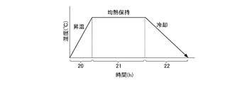
- the nitriding treatment method for exhaust system parts includes a preparation step, a temperature raising step, a film removal step, a soaking step, and a cooling step, which are sequentially processed in the same vacuum furnace.
- the chromium oxynitride film 17 is formed by a gas nitriding method.
- a cover made of mild steel is attached to the outer peripheral side of the exhaust gas cooling pipe 7 to prevent nitriding.
- the exhaust gas cooling pipe 7 is installed in the furnace (step S1).
- step S3 a mixed gas of hydrogen sulfide (H 2 S) gas and ammonia (NH 3 ) gas is introduced into the furnace (step S3).
- H 2 S hydrogen sulfide
- NH 3 ammonia
- the hydrogen sulfide gas reacts with an oxide film mainly composed of chromium oxide (CrO x ) formed in advance to remove the oxide film (film removal step).
- an oxide film mainly composed of chromium oxide (CrO x ) formed in advance to remove the oxide film (film removal step).
- hydrogen sulfide is used in the film removal process, but the present invention is not limited to this, and any gas may be used as long as it can remove the oxide film.
- a mixed gas of hydrogen sulfide gas and ammonia gas is introduced into the furnace to treat the film removal step, but the present invention is not limited to this.
- the temperature rising process may be started after introducing the mixed gas with the ammonia gas into the furnace, and the film removal process may be performed at the same time.
- the furnace is maintained at 570 ° C. for 8 hours (reference numeral 21 in FIG. 3).
- the exhaust gas cooling pipe 7 and the furnace atmosphere are maintained soaking (soaking process).
- part of the ammonia gas in the atmosphere is decomposed into nitrogen and hydrogen.
- nitrogen atoms in the atmosphere enter the surface layer of the wall portion 7 c of the exhaust gas cooling pipe 7.
- chromium which is a component of stainless steel, oxygen forming the oxide film, and nitrogen that has entered the surface layer combine to produce chromium oxynitride.
- the chromium oxynitride film 17 is formed on the inner peripheral surface of the wall 7c.
- the exhaust gas cooling pipe 7 is cooled relatively slowly to about room temperature (cooling process).
- Exhaust gas G is supplied from the engine exhaust device to the EGR cooler 1 through the EGR gas supply pipe 13.
- the exhaust gas G is circulated in the order of the exhaust gas inflow pipe 8 ⁇ the exhaust gas cooling pipe 7 ⁇ the exhaust gas outflow pipe 9.
- the exhaust gas G discharged from the EGR cooler 1 is supplied to the intake device of the engine through the EGR gas discharge pipe 14.
- the cooling medium W is supplied from the supply pump to the EGR cooler 1 through the cooling medium supply pipe 15.
- the cooling medium W is circulated in the order of the cooling medium inflow pipe 4 ⁇ the case body 10 ⁇ the cooling medium outflow pipe 5.
- the cooling medium W discharged from the EGR cooler 1 is supplied to the water jacket of the engine through the cooling medium discharge pipe 16.
- the exhaust gas G that circulates inside is cooled by heat exchange with the cooling medium W that circulates outside. At this time, water vapor contained in the exhaust gas G is condensed to form water droplets on the chromium oxynitride film 17 formed on the inner surface of the exhaust gas cooling pipe 7.
- the chromium oxynitride film 17 has high corrosion resistance against sulfuric acid, nitric acid, hydrochloric acid, and the like. For this reason, corrosion of the wall 7c of the exhaust gas cooling pipe 7 is suppressed.
- nitrogen elutes from the chromium oxynitride film 17 into the acidic aqueous solution attached to the inner peripheral side of the wall 7c of the exhaust gas cooling pipe 7.
- This nitrogen combines with hydrogen in an acidic aqueous solution to produce ammonium ions. Since hydrogen in the acidic aqueous solution is used for the production of ammonium ions, the hydrogen ion concentration of the acidic aqueous solution in the exhaust gas cooling pipe 7 is lowered.
- the chromium oxynitride film 17 is formed on the inner peripheral surface of the wall portion 7 c of the exhaust gas cooling pipe 7. For this reason, the corrosion resistance of the wall 7c of the exhaust gas cooling pipe 7 is improved. Thereby, even if the inner peripheral side of the wall 7c is exposed to strong hydrochloric acid, corrosion of the wall 7c is suppressed.
- the gas nitriding method is employed to form the chromium oxynitride film 17 on the wall 7c of the exhaust gas cooling pipe 7, the equipment can be simplified as compared with other nitriding methods. For this reason, the increase in cost can be suppressed.
- the chromium oxynitride film 17 is formed on the inner peripheral side of the wall portion 7c of the exhaust gas cooling pipe 7, but in the EGR cooler according to the present invention, for example, a chromium oxynitride film may be formed on the inner peripheral side of the wall portion of the exhaust gas inflow pipe 8 or the exhaust gas outflow pipe 9.
- a chromium oxynitride film is formed on the walls of the exhaust gas cooling pipe 7, the exhaust gas inflow pipe 8 and the exhaust gas outflow pipe 9, or the exhaust gas cooling pipe 7 and the exhaust gas outflow pipe 9.
- a chromium oxynitride film can be formed only on the wall.
- a chromium oxynitride film may be formed on a wall portion of a member other than the exhaust gas cooling pipe 7, the exhaust gas inflow pipe 8, and the exhaust gas outflow pipe 9.
- the chromium oxynitride film 17 is formed on the entire surface layer on the inner peripheral side of the wall portion 7c of the exhaust gas cooling pipe 7, but the EGR according to the present invention.
- the cooler is not limited to this.
- the chromium oxynitride film 17 may be formed only on a portion of the surface layer on the inner peripheral side of the wall portion 7 c of the exhaust gas cooling pipe 7.
- the soaking temperature in the soaking process is 570 ° C. and the soaking time is 8 hours.
- the soaking temperature may be 300 ° C. to 590 ° C., and the soaking time may be 6 to 10 hours. In this case, the higher the soaking temperature, the shorter the soaking time.
- the gas nitriding method is adopted to form the chromium oxynitride film 17, but the EGR cooler according to the present invention is not limited to this, for example, plasma Other nitriding methods such as a nitriding method, a salt bath nitriding method, and a gas soft nitriding method may be employed.
- the exhaust system component of the present embodiment is applied to the EGR cooler 1, but the exhaust system component according to the present invention is not limited to this, and for example, an exhaust manifold or exhaust gas
- the present invention can be applied to all parts constituting an exhaust device such as a pipe.
- the exhaust system component according to the present invention and the EGR cooler using the exhaust system component are useful for exhaust system components suitable for improving corrosion resistance and for general EGR coolers using the exhaust system component.
- the corrosion resistance test was performed using stainless steel (SUS316L) whose surface layer was subjected to various nitriding treatments as a sample.
- SUS316L stainless steel
- a process of immersing and heating the sample in a mixed solution of sulfuric acid and hydrochloric acid, drying and moistening was taken as one cycle.
- the maximum erosion depth in the surface layer of the sample was measured at the end of 10 and / or 20 cycles.
- the maximum erosion depth was set to 1.0 using the measurement value of Comparative Example 1 as a reference value, and the measurement values of other examples were converted into a ratio with respect to the reference value and expressed in units.
- the sample was nitrided by plasma nitriding.
- the treatment atmosphere was nitrogen gas and hydrogen gas.
- the heating temperature was 570 ° C.
- the soaking time was 4 hours.
- This sample was subjected to 10 cycles of corrosion resistance test. As a result, as shown in FIG. 4, the maximum erosion depth in the surface layer of the sample was 0.0.
- the nitriding treatment of the sample was performed by the A nitriding method.
- the treatment atmosphere was a general nitrogen treatment gas.
- the heating temperature was 500 ° C. to 600 ° C.
- the soaking time was 1 to 3 hours.
- This sample was subjected to 10 cycles and 20 cycles of corrosion resistance test. As a result, as shown in FIG. 4, in all cases, the maximum erosion depth in the surface layer of the sample was 0.0.
- the nitriding treatment of the sample was performed by the B nitriding method.
- the treatment atmosphere was a general nitrogen treatment gas.
- the heating temperature was 350 ° C. to 450 ° C.
- the soaking time was 40 to 60 hours.
- This sample was subjected to 10 cycles of corrosion resistance test. As a result, as shown in FIG. 4, the maximum erosion depth in the surface layer of the sample was 0.0.
- the sample was not nitrided. This sample was subjected to 10 cycles of corrosion resistance test. As a result, as shown in FIG. 4, the maximum erosion depth in the surface layer of the sample was 1.0.
- the sample was not nitrided. This sample was subjected to 10 cycles of corrosion resistance test. As a result, as shown in FIG. 4, the maximum erosion depth in the surface layer of the sample was 1.1.
- the sample was not nitrided. This sample was subjected to 20 cycles of corrosion resistance test. As a result, as shown in FIG. 4, the maximum erosion depth in the surface layer of the sample was 1.4.
- the sample was not nitrided. This sample was subjected to 20 cycles of corrosion resistance test. As a result, as shown in FIG. 4, the maximum erosion depth in the surface layer of the sample was 2.2.
- the sample was not nitrided. This sample was subjected to 20 cycles of corrosion resistance test. As a result, as shown in FIG. 4, the maximum erosion depth in the surface layer of the sample was 3.1.
- the sample was not nitrided. This sample was subjected to 20 cycles of corrosion resistance test. As a result, as shown in FIG. 4, the maximum erosion depth in the surface layer of the sample was 3.4.
- Cooling medium inflow pipe 5 Cooling medium outflow pipe 7
- Exhaust gas inflow pipe 9 Exhaust gas outflow pipe 17 Chromium oxynitride film G
- Exhaust gas W Cooling medium S2 Temperature raising step S3 Film removal step S4 Soaking step S5 Cooling step
Landscapes
- Engineering & Computer Science (AREA)
- General Engineering & Computer Science (AREA)
- Mechanical Engineering (AREA)
- Chemical & Material Sciences (AREA)
- Combustion & Propulsion (AREA)
- Thermal Sciences (AREA)
- Physics & Mathematics (AREA)
- Manufacturing & Machinery (AREA)
- Health & Medical Sciences (AREA)
- Chemical Kinetics & Catalysis (AREA)
- Toxicology (AREA)
- Exhaust-Gas Circulating Devices (AREA)
- Solid-Phase Diffusion Into Metallic Material Surfaces (AREA)
- Exhaust Silencers (AREA)
Abstract
Description
2 ケース
4 冷却媒体流入管
5 冷却媒体流出管
7 排出ガス冷却管(排気系部品)
8 排出ガス流入管
9 排出ガス流出管
17 酸窒化クロム膜
G 排出ガス
W 冷却媒体
S2 昇温工程
S3 除膜工程
S4 均熱保持工程
S5 冷却工程
Claims (6)
- 内燃機関の排出ガスが流通されるとともに、
前記排出ガスが供給される上流側端部と、
前記排出ガスが排出される下流側端部と、
前記上流側端部および前記下流側端部の間に設けられ前記排出ガスが流通される方向に延在される環状に形成された壁部と、
を備えたステンレス鋼からなる排気系部品において、
前記壁部の内周側の表層にCrOxNy膜からなる酸窒化クロム膜が形成されていることを特徴とする排気系部品。 - 前記酸窒化クロム膜は、前記壁部の前記内周側のうちの前記排出ガスが接触する部位の全域に形成されていることを特徴とする請求項1に記載の排気系部品。
- 前記酸窒化クロム膜は、前記表層に予め形成されていた酸化膜を除去して前記表層に窒素を添加することにより、前記表層と前記窒素とが反応して前記表層に窒化処理が施されて形成されたものであることを特徴とする請求項1または請求項2に記載の排気系部品。
- 前記酸窒化クロム膜は、付着した酸性水溶液に窒素を溶出し、前記窒素が前記酸性水溶液中で水素と化合してアンモニウムイオンを生成し、前記酸性水溶液の水素イオン濃度を低下させる機能を有することを特徴とする請求項1ないし請求項3のいずれか一項に記載の排気系部品。
- ケースと、
前記ケースに冷却媒体を流入させる冷却媒体流入管と、
前記ケースから前記冷却媒体を流出させる冷却媒体流出管と、
前記ケースに収容される管からなるとともに、内燃機関の排出ガスを内部に流通させ、外部を流通する前記冷却媒体と前記排出ガスとで熱交換して前記排出ガスを冷却する排出ガス冷却管と、
前記ケースの外部で前記排出ガス冷却管の前記排出ガスの流通方向の上流側端部に連結される排出ガス流入管と、
前記ケースの外部で前記排出ガス冷却管の前記排出ガスの流通方向の下流側端部に連結されるとともに、前記排出ガス冷却管で冷却された前記排出ガスを前記内燃機関の吸気装置に供給する排出ガス流出管と、
を備えたEGRクーラにおいて、
前記排出ガス冷却管、前記排出ガス流入管および前記排出ガス流出管のうちの少なくともいずれか1つが請求項1ないし請求項4のいずれか一項に記載の排気系部品であることを特徴とするEGRクーラ。 - 内燃機関の排出ガスが流通されるとともに、
前記排出ガスが供給される上流側端部と、
前記排出ガスが排出される下流側端部と、
前記上流側端部および前記下流側端部の間に設けられ前記排出ガスが流通される方向に延在される環状に形成された壁部と、
を備えたステンレス鋼からなる排気系部品の前記壁部の内周側の表層に窒化処理を施す排気系部品の窒化処理方法において、
前記表層に予め形成されていた酸化膜を除去する除膜工程と、
窒化処理ガスを充填した空間内において前記排気系部品を昇温することにより前記表層に窒素を添加する昇温工程と、
前記排気系部品を所定時間均熱保持することにより前記表層と前記窒素とを反応させて前記表層にCrOxNy膜からなる酸窒化クロム膜を形成する均熱保持工程と、
前記排気系部品を冷却する冷却工程とを備えることを特徴とする排気系部品の窒化処理方法。
Priority Applications (5)
| Application Number | Priority Date | Filing Date | Title |
|---|---|---|---|
| DE112011105282.0T DE112011105282T5 (de) | 2011-05-26 | 2011-05-26 | Abgassystem-Teil, Abgasrückführungs-Kühler und Verfahren zum Nitrieren eines Abgassystem-Teils |
| JP2012530806A JP5293899B2 (ja) | 2011-05-26 | 2011-05-26 | 排気系部品およびegrクーラ、ならびに排気系部品の窒化処理方法 |
| PCT/JP2011/002934 WO2012160606A1 (ja) | 2011-05-26 | 2011-05-26 | 排気系部品およびegrクーラ、ならびに排気系部品の窒化処理方法 |
| CN2011800116089A CN102906412A (zh) | 2011-05-26 | 2011-05-26 | 排气系统部件和egr冷却器以及排气系统部件的氮化处理方法 |
| US13/521,315 US20140216423A1 (en) | 2011-05-26 | 2011-05-26 | Exhaust system part, egr cooler, and method of nitriding exhaust system part |
Applications Claiming Priority (1)
| Application Number | Priority Date | Filing Date | Title |
|---|---|---|---|
| PCT/JP2011/002934 WO2012160606A1 (ja) | 2011-05-26 | 2011-05-26 | 排気系部品およびegrクーラ、ならびに排気系部品の窒化処理方法 |
Publications (1)
| Publication Number | Publication Date |
|---|---|
| WO2012160606A1 true WO2012160606A1 (ja) | 2012-11-29 |
Family
ID=47216713
Family Applications (1)
| Application Number | Title | Priority Date | Filing Date |
|---|---|---|---|
| PCT/JP2011/002934 Ceased WO2012160606A1 (ja) | 2011-05-26 | 2011-05-26 | 排気系部品およびegrクーラ、ならびに排気系部品の窒化処理方法 |
Country Status (5)
| Country | Link |
|---|---|
| US (1) | US20140216423A1 (ja) |
| JP (1) | JP5293899B2 (ja) |
| CN (1) | CN102906412A (ja) |
| DE (1) | DE112011105282T5 (ja) |
| WO (1) | WO2012160606A1 (ja) |
Cited By (1)
| Publication number | Priority date | Publication date | Assignee | Title |
|---|---|---|---|---|
| CN111441855A (zh) * | 2019-01-17 | 2020-07-24 | 天纳克汽车经营有限公司 | 扩散表面合金金属排气部件 |
Families Citing this family (7)
| Publication number | Priority date | Publication date | Assignee | Title |
|---|---|---|---|---|
| DE102013221102A1 (de) * | 2013-10-17 | 2015-05-07 | Mahle International Gmbh | Stahlkolben für eine Brennkraftmaschine und Verfahren zu dessen Herstellung |
| JP6135822B2 (ja) * | 2014-04-04 | 2017-05-31 | 日産自動車株式会社 | エンジンの排気装置 |
| US9506389B2 (en) | 2015-03-05 | 2016-11-29 | Caterpillar Inc. | System and method for nitriding components of aftertreatment system |
| US9957863B2 (en) * | 2016-06-27 | 2018-05-01 | Indmar Products Company, Inc. | Exhaust conduits for marine engine exhaust systems |
| US10385769B2 (en) * | 2016-08-30 | 2019-08-20 | Caterpillar Inc. | Fuel reformer cooler |
| US10400714B2 (en) * | 2017-09-28 | 2019-09-03 | Senior Ip Gmbh | Heat exchanger with annular coolant chamber |
| US10464652B2 (en) | 2018-01-23 | 2019-11-05 | Indmar Products Company Inc. | Riser conduits having inner tube extensions for marine engine exhaust systems |
Citations (4)
| Publication number | Priority date | Publication date | Assignee | Title |
|---|---|---|---|---|
| JP2003075091A (ja) * | 2001-08-31 | 2003-03-12 | Usui Internatl Ind Co Ltd | Egrクーラー |
| JP2007120386A (ja) * | 2005-10-27 | 2007-05-17 | Komatsu Ltd | 摺動部材支持構造およびバルブ |
| WO2007099809A1 (ja) * | 2006-02-22 | 2007-09-07 | Komatsu Ltd. | 排気ガス再循環装置 |
| JP2010101239A (ja) * | 2008-10-23 | 2010-05-06 | Toyota Motor Corp | 内燃機関のegrクーラー |
Family Cites Families (7)
| Publication number | Priority date | Publication date | Assignee | Title |
|---|---|---|---|---|
| EP1685322A1 (en) * | 2003-10-17 | 2006-08-02 | Honeywell International, Inc. | Internal bypass exhaust gas cooler |
| KR100791274B1 (ko) * | 2007-06-20 | 2008-01-04 | 현대하이스코 주식회사 | 금속층/금속질화물층과 금속산질화물층을 포함하는 연료전지용 스테인리스 |
| JP4561817B2 (ja) * | 2007-12-04 | 2010-10-13 | トヨタ自動車株式会社 | 内燃機関 |
| KR100992545B1 (ko) * | 2008-08-26 | 2010-11-08 | 현대자동차주식회사 | 차량용 이지알쿨러 및 그 제조방법 |
| JP5048695B2 (ja) * | 2009-02-27 | 2012-10-17 | 株式会社小松製作所 | Egrクーラ |
| CN102534525A (zh) * | 2010-12-25 | 2012-07-04 | 鸿富锦精密工业(深圳)有限公司 | 镀膜件及其制备方法 |
| JP2013053769A (ja) * | 2011-09-01 | 2013-03-21 | Toyota Motor Corp | 排気系部品および排気系部品の表層の形成方法 |
-
2011
- 2011-05-26 JP JP2012530806A patent/JP5293899B2/ja not_active Expired - Fee Related
- 2011-05-26 US US13/521,315 patent/US20140216423A1/en not_active Abandoned
- 2011-05-26 DE DE112011105282.0T patent/DE112011105282T5/de not_active Withdrawn
- 2011-05-26 CN CN2011800116089A patent/CN102906412A/zh active Pending
- 2011-05-26 WO PCT/JP2011/002934 patent/WO2012160606A1/ja not_active Ceased
Patent Citations (4)
| Publication number | Priority date | Publication date | Assignee | Title |
|---|---|---|---|---|
| JP2003075091A (ja) * | 2001-08-31 | 2003-03-12 | Usui Internatl Ind Co Ltd | Egrクーラー |
| JP2007120386A (ja) * | 2005-10-27 | 2007-05-17 | Komatsu Ltd | 摺動部材支持構造およびバルブ |
| WO2007099809A1 (ja) * | 2006-02-22 | 2007-09-07 | Komatsu Ltd. | 排気ガス再循環装置 |
| JP2010101239A (ja) * | 2008-10-23 | 2010-05-06 | Toyota Motor Corp | 内燃機関のegrクーラー |
Cited By (1)
| Publication number | Priority date | Publication date | Assignee | Title |
|---|---|---|---|---|
| CN111441855A (zh) * | 2019-01-17 | 2020-07-24 | 天纳克汽车经营有限公司 | 扩散表面合金金属排气部件 |
Also Published As
| Publication number | Publication date |
|---|---|
| DE112011105282T5 (de) | 2014-02-20 |
| JPWO2012160606A1 (ja) | 2014-07-31 |
| JP5293899B2 (ja) | 2013-09-18 |
| CN102906412A (zh) | 2013-01-30 |
| US20140216423A1 (en) | 2014-08-07 |
Similar Documents
| Publication | Publication Date | Title |
|---|---|---|
| JP5293899B2 (ja) | 排気系部品およびegrクーラ、ならびに排気系部品の窒化処理方法 | |
| JPH089766B2 (ja) | 鋼の窒化方法 | |
| CN103243339A (zh) | 一种中铬超纯铁素体不锈钢连续退火酸洗方法 | |
| CN104603319B (zh) | 钢制零件的表面抗氧化处理的方法和设备 | |
| US10557180B2 (en) | Heat treating device | |
| TWI406701B (zh) | 使來自退火及酸浸管線之廢氣去氮氧化之方法及特別是用於不銹鋼之熱軋或冷軋之退火及酸浸管線 | |
| US8414710B2 (en) | Method for surface treatment of metal material | |
| KR101245564B1 (ko) | 스테인레스강, 내열강 및 고합금강에 대한 가스질화방법 | |
| JP2013173982A (ja) | 排気系部品および排気系部品の窒化処理方法 | |
| JP2013053769A (ja) | 排気系部品および排気系部品の表層の形成方法 | |
| RU2014126218A (ru) | Блокирующий диффузию слой в устройстве для очистки отработавшего газа | |
| JP4239006B2 (ja) | 硝酸廃液の処理方法 | |
| JP2001179051A (ja) | 水素含有排ガスの除害方法及び除害装置 | |
| KR20140036011A (ko) | 강철 처리 방법 및 강철 처리 설비 | |
| JP2007245055A (ja) | 船舶用排ガス浄化装置の排出液処理方法 | |
| JP3556181B2 (ja) | 装置内部腐蝕防止手段を備えたガススクラバー | |
| JPH0754123A (ja) | 鋼の窒化方法 | |
| JP2007090337A (ja) | 化学洗浄廃液の処理方法 | |
| CN106164431B (zh) | 用于废气处理系统的加热系统 | |
| US6020025A (en) | Method of manufacturing a crank shaft | |
| JPS6011621A (ja) | 内面からの腐蝕を防止した消音器 | |
| EP3613865A1 (en) | Aluminum alloy material having improved corrosion resistance for gas tube in egr cooler | |
| KR100213404B1 (ko) | 경질 오스테나이트계 스테인레스 나사 및 그 제조방법 | |
| CN211706383U (zh) | 一种冷酸退火炉氨水脱硝系统 | |
| JP3428776B2 (ja) | 鋼の窒化方法 |
Legal Events
| Date | Code | Title | Description |
|---|---|---|---|
| WWE | Wipo information: entry into national phase |
Ref document number: 201180011608.9 Country of ref document: CN |
|
| ENP | Entry into the national phase |
Ref document number: 2012530806 Country of ref document: JP Kind code of ref document: A |
|
| WWE | Wipo information: entry into national phase |
Ref document number: 13521315 Country of ref document: US |
|
| 121 | Ep: the epo has been informed by wipo that ep was designated in this application |
Ref document number: 11866240 Country of ref document: EP Kind code of ref document: A1 |
|
| WWE | Wipo information: entry into national phase |
Ref document number: 1120111052820 Country of ref document: DE Ref document number: 112011105282 Country of ref document: DE |
|
| 122 | Ep: pct application non-entry in european phase |
Ref document number: 11866240 Country of ref document: EP Kind code of ref document: A1 |