WO2012157501A1 - 金属接合体 - Google Patents
金属接合体 Download PDFInfo
- Publication number
- WO2012157501A1 WO2012157501A1 PCT/JP2012/061947 JP2012061947W WO2012157501A1 WO 2012157501 A1 WO2012157501 A1 WO 2012157501A1 JP 2012061947 W JP2012061947 W JP 2012061947W WO 2012157501 A1 WO2012157501 A1 WO 2012157501A1
- Authority
- WO
- WIPO (PCT)
- Prior art keywords
- pair
- cutting lines
- metal
- cutting
- line
- Prior art date
- Legal status (The legal status is an assumption and is not a legal conclusion. Google has not performed a legal analysis and makes no representation as to the accuracy of the status listed.)
- Ceased
Links
Images




Classifications
-
- B—PERFORMING OPERATIONS; TRANSPORTING
- B21—MECHANICAL METAL-WORKING WITHOUT ESSENTIALLY REMOVING MATERIAL; PUNCHING METAL
- B21D—WORKING OR PROCESSING OF SHEET METAL OR METAL TUBES, RODS OR PROFILES WITHOUT ESSENTIALLY REMOVING MATERIAL; PUNCHING METAL
- B21D39/00—Application of procedures in order to connect objects or parts, e.g. coating with sheet metal otherwise than by plating; Tube expanders
- B21D39/03—Application of procedures in order to connect objects or parts, e.g. coating with sheet metal otherwise than by plating; Tube expanders of sheet metal otherwise than by folding
- B21D39/031—Joining superposed plates by locally deforming without slitting or piercing
-
- F—MECHANICAL ENGINEERING; LIGHTING; HEATING; WEAPONS; BLASTING
- F16—ENGINEERING ELEMENTS AND UNITS; GENERAL MEASURES FOR PRODUCING AND MAINTAINING EFFECTIVE FUNCTIONING OF MACHINES OR INSTALLATIONS; THERMAL INSULATION IN GENERAL
- F16B—DEVICES FOR FASTENING OR SECURING CONSTRUCTIONAL ELEMENTS OR MACHINE PARTS TOGETHER, e.g. NAILS, BOLTS, CIRCLIPS, CLAMPS, CLIPS OR WEDGES; JOINTS OR JOINTING
- F16B4/00—Shrinkage connections, e.g. assembled with the parts at different temperature; Force fits; Non-releasable friction-grip fastenings
-
- F—MECHANICAL ENGINEERING; LIGHTING; HEATING; WEAPONS; BLASTING
- F16—ENGINEERING ELEMENTS AND UNITS; GENERAL MEASURES FOR PRODUCING AND MAINTAINING EFFECTIVE FUNCTIONING OF MACHINES OR INSTALLATIONS; THERMAL INSULATION IN GENERAL
- F16B—DEVICES FOR FASTENING OR SECURING CONSTRUCTIONAL ELEMENTS OR MACHINE PARTS TOGETHER, e.g. NAILS, BOLTS, CIRCLIPS, CLAMPS, CLIPS OR WEDGES; JOINTS OR JOINTING
- F16B2200/00—Constructional details of connections not covered for in other groups of this subclass
- F16B2200/93—Fastener comprising feature for establishing a good electrical connection, e.g. electrostatic discharge or insulation feature
-
- F—MECHANICAL ENGINEERING; LIGHTING; HEATING; WEAPONS; BLASTING
- F16—ENGINEERING ELEMENTS AND UNITS; GENERAL MEASURES FOR PRODUCING AND MAINTAINING EFFECTIVE FUNCTIONING OF MACHINES OR INSTALLATIONS; THERMAL INSULATION IN GENERAL
- F16B—DEVICES FOR FASTENING OR SECURING CONSTRUCTIONAL ELEMENTS OR MACHINE PARTS TOGETHER, e.g. NAILS, BOLTS, CIRCLIPS, CLAMPS, CLIPS OR WEDGES; JOINTS OR JOINTING
- F16B5/00—Joining sheets or plates, e.g. panels, to one another or to strips or bars parallel to them
- F16B5/04—Joining sheets or plates, e.g. panels, to one another or to strips or bars parallel to them by means of riveting
- F16B5/045—Joining sheets or plates, e.g. panels, to one another or to strips or bars parallel to them by means of riveting without the use of separate rivets
-
- Y—GENERAL TAGGING OF NEW TECHNOLOGICAL DEVELOPMENTS; GENERAL TAGGING OF CROSS-SECTIONAL TECHNOLOGIES SPANNING OVER SEVERAL SECTIONS OF THE IPC; TECHNICAL SUBJECTS COVERED BY FORMER USPC CROSS-REFERENCE ART COLLECTIONS [XRACs] AND DIGESTS
- Y10—TECHNICAL SUBJECTS COVERED BY FORMER USPC
- Y10T—TECHNICAL SUBJECTS COVERED BY FORMER US CLASSIFICATION
- Y10T403/00—Joints and connections
- Y10T403/49—Member deformed in situ
Definitions
- the present invention relates to a metal joined body, and more particularly to a metal joined body in which two or more metal plates are joined together.
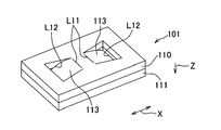
- Patent Document 1 discloses a method of joining two metal plates 110 and 111 as shown in FIGS. Two metal plates 110 and 111 are cut along a cutting line L12 extending from the end of the line L11 to the other end of the fold line L11 through a side away from the fold line L11. A method for joining the metal plates 110 and 111 by pressing (pressing) a portion surrounded by the cutting line L12 and the folding line L11 of the plates 110 and 111 so as to be bent along the folding line L11 is proposed. Has been.
- the metal bonded body 101 having this metal bonded portion has a pair of protruding portions 113 protruding in the pressing direction (ie, arrow Z) by pressing (pressing) a portion surrounded by the cutting line L12 and the bending line L11. Is provided.
- the protrusion 113 is formed in a trapezoidal shape when viewed from above, and the pair of protrusions 113 formed in the trapezoidal shape are spaced from each other at positions where the short sides (that is, the folding lines L11) face each other. Are arranged.
- a pair of pressing jigs that are gradually tapered toward the tip end portion is provided on a mold used when pressing (pressing) the two metal plates 110 and 111.
- the pair of pressing jigs are provided at a position where each of the pair of protrusions 113 formed in a trapezoidal shape is spaced apart from each other.
- the metal joined body described in Patent Document 1 was able to obtain good electrical characteristics by providing a metal joined portion. However, when a drop impact test was performed on the metal joined body described in Patent Document 1, the joining was lost and the electrical characteristics were deteriorated. That is, the metal joined body described in Patent Document 1 has a problem that it can obtain good electrical characteristics but has insufficient mechanical joint strength.
- Patent Document 2 as a method of joining metal plates, as shown in FIG. 9, plastic deformation is performed such that two metal plates 110 and 111 are overlapped and locally collapsed into a circular shape.
- a metal joined body in which a caulking joint portion 114 is formed. In the caulking joint 114, a part of the metal plate 110 is fitted to the metal plate 111 side.
- the metal joined body described in Patent Document 2 has a problem that electrical characteristics are not good because of joining by caulking even though the mechanical strength is high.
- the metal joined body described in Patent Document 2 also has a problem that when the rotating force is applied, the joining easily comes off.
- an object of the present invention is to provide a metal joined body in which both electrical characteristics and mechanical strength are improved.
- the invention according to claim 1 for solving the above-described problem is a metal joined body in which two or more metal plates are joined to each other, and a pair of first plates arranged on the two or more metal plates at intervals.
- a pair of first cutting lines extending along the arrangement direction, and a pair of first cutting lines, and arranged side by side in a direction perpendicular to the arrangement direction with respect to each of the pair of first cutting lines,
- a pair of second cutting lines extending along the arrangement direction, and a pair of third cutting lines extending in a direction away from the second cutting line from ends in a direction approaching each other in the pair of first cutting lines.
- a cutting line, a pair of fourth cutting lines extending in a direction away from the first cutting line from ends in a direction approaching each other in the pair of second cutting lines, and the two or more metal plates are stacked.
- the two or more gold along the first to fourth cutting lines.
- a central caulking portion formed by cutting a plate and pressing and denting a portion surrounded by the first to fourth cutting lines, and a metal provided on a cutting surface of the first to fourth cutting lines And a joined part.
- the portion sandwiched between the pair of third cutting lines and the portion sandwiched between the pair of fourth cutting lines in the two or more metal plates are at the center of the central caulking portion. It exists in the taper shape which becomes deep as it goes, It exists in the metal joined body of Claim 1 characterized by the above-mentioned.
- the portion sandwiched between the pair of first cutting lines and the pair of second cutting lines in the two or more metal plates is provided perpendicular to the plane of the metal plate. It exists in the metal joined body of Claim 2 characterized by the above-mentioned.
- the width between the pair of third cutting lines and the width between the pair of fourth cutting lines become narrower as the distance from the first cutting line and the second cutting line increases. It exists in the metal joined body of Claim 2 characterized by the above-mentioned.
- the portion sandwiched between the pair of third cutting lines and the portion sandwiched between the pair of fourth cutting lines in the two or more metal plates are directed toward the center of the central caulking portion.
- the width between a pair of 3rd cutting lines and the width between a pair of 4th cutting lines are provided so that it may become narrow as it leaves
- FIG. 2 is a cross-sectional view of the metal joined body shown in FIG. 1 taken along the line II.
- FIG. 2 is a cross-sectional view of the metal joined body shown in FIG. 1 taken along line II-II.
- FIG. 3 is a sectional view of the metal joined body shown in FIG. 1 taken along the line III-III.
- FIG. 6 is a perspective view of a metal bonding apparatus for manufacturing the metal bonded body shown in FIGS. It is a perspective view which shows an example of the conventional metal joined body. It is a top view of the metal joined body shown in FIG. It is a section perspective view showing an example of the conventional metal zygote.
- FIG. 1 is a perspective view of a metal joined body of the present invention.
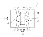
- FIG. 2 is a top view of the metal joined body shown in FIG.
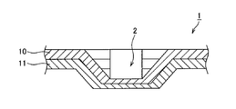
- FIG. 3 is a cross-sectional view taken along the line II of the metal joined body shown in FIG. 4 is a cross-sectional view of the metal joined body shown in FIG. 1 taken along the line II-II.
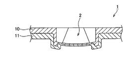
- FIG. 5 is a sectional view of the metal joined body shown in FIG. 1 taken along the line III-III.
- the metal joined body 1 includes, for example, two metal plates 10 and 11 made of the same metal and formed to have the same plate thickness.
- the metal plates 10, 11 include a pair of first cutting lines L1, a pair of second cutting lines L2, a pair of third cutting lines L3, and a pair of fourth cutting lines.
- a cutting line L4 is provided.
- the pair of first cutting lines L1 are arranged on the metal plates 10 and 11 with a space therebetween, and extend along the arrangement direction Y1.
- the pair of second cutting lines L2 are arranged to face each other in the orthogonal direction Y2 with respect to each of the pair of first cutting lines L1.
- the orthogonal direction Y2 is a direction orthogonal to the arrangement direction Y1.
- the pair of second cutting lines L2 also extend along the alignment direction Y1.
- the first cutting line L1 and the second cutting line L2 are provided in parallel to each other.
- the pair of third cutting lines L3 extend in the direction away from the second cutting line L2 from the ends of the pair of first cutting lines L1 that are close to each other.
- the width between the pair of third cutting lines L3 is provided so as to decrease as the distance from the first cutting line L1 increases.
- the pair of fourth cutting lines L4 extends in the direction away from the first cutting line L1 from the ends in the direction in which the pair of second cutting lines L2 approach each other.
- the width of the pair of fourth cutting lines L4 is provided so as to become narrower as the distance from the second cutting line L2 increases.
- the metal joined body 1 is provided with a center caulked portion 2 and a metal joined portion 3.
- the central caulking portion 2 cuts the metal plates 10 and 11 along the first to fourth cutting lines L1 to L4 in a state where the metal plates 10 and 11 are overlapped, and the first to fourth cutting lines. It is formed by pressing and denting the central part surrounded by L1 to L4.
- the metal plates 10 and 11 are plastically deformed, and a part of the metal plate 10 is fitted to the metal plate 11 side.
- the line connecting the ends of the first cutting line L1 and the second cutting line L2 on the side away from the third cutting line L3 and the fourth cutting line L4 is a folding line.
- L5 and L6 are the metal plates 10 and 11, as shown in FIG. 4, the portions sandwiched between the pair of first cutting lines L1 and the pair of second cutting lines L2. It is bent so as to be perpendicular to the 11 planes.
- the ends of the pair of third cutting lines L3 on the side away from the first cutting line L1 are separated from the second cutting line L2 of the pair of fourth cutting lines L4.
- Lines connecting the end portions on the side become the folding line L7, the end portions on the first cutting line L1 side of the pair of third cutting lines L3, and the second cutting line L2 side of the pair of fourth cutting lines L4.
- a line connecting the ends is a folding line L8.
- the folding lines L7 and L8 include a portion sandwiched between the pair of third cutting lines L3 and a portion sandwiched between the pair of fourth cutting lines L4 in the metal plates 10, 11.
- the taper is bent so as to become deeper toward the center of the center caulking portion 2.
- the cutting surfaces inside the pair of third cutting lines L3 are paired with the third cutting lines. Rub against the cut surface outside L3. Therefore, the oxide film on the cut surfaces of the pair of third cutting lines L3 is removed by friction to expose the new surface, and as shown in FIG. 5, the cutting surface inside the third cutting line L3 and the outside of the third cutting line L3. As a result, the metal joint 3 is obtained. Similarly, the metal joining part 3 is obtained also in the cut surface of a pair of 4th cutting lines L4.
- the metal joint 3 is partially obtained on the cut surfaces of the first and second cutting lines L1 and L2.
- the inventors manufactured the product of the present invention shown in FIG. 1, the conventional product shown in FIG. 7, and the conventional product shown in FIG. 9, and conducted a drop impact test to confirm the effect of the present invention. .
- the electrical characteristics deteriorated such as the disconnection or the resistance value increased in the conventional product shown in FIG. 9. There was no decline in
- the metal bonding apparatus 20 includes a first mold 21, a second mold 22, and a guide 23.
- the first mold 21 is provided in a rectangular parallelepiped shape, for example, and a press hole 24 is provided on the upper surface thereof.
- the press hole 24 is formed in the same shape as the portion surrounded by the first to fourth cutting lines L1 to L4 and the folding lines L5 and L7.
- the press hole 24 is provided so that the depth gradually decreases from the portion 24a where the fold line L8 is overlapped to the edge 24b where the fold line L7 is overlapped. Further, the press hole 24 is deepened vertically from the edge 24c where the folding line L5 is overlapped.
- the second mold 22 is provided in a bar shape.
- the second mold 22 is formed in the same shape as the portion surrounded by the first to fourth cutting lines L1 to L4 and the folding lines L5 and L7.
- the second mold 22 is provided with a taper that gradually separates from the first mold 21 toward the edge 22b where the fold line L7 is overlapped from the portion 22a where the fold line L8 is overlapped.
- the guide 23 is provided in a rectangular parallelepiped shape, for example, and is provided with a guide hole 23 a that is overlapped with the press hole 24.
- the guide hole 23a penetrates the guide 23 along the pressing direction.
- the guide hole 23a is formed in the same shape as the portion surrounded by the first to fourth cutting lines L1 to L4 and the folding lines L5 and L7, and the first die 22 is inserted into the first hole 23a. Guide to the press hole 24 of the mold 21.
- the metal plates 10 and 11 stacked on each other are stacked on the upper surface of the first mold 21. Thereafter, the second die 22 is moved along the pressing direction along the guide hole 23 a of the guide 23, and the metal plates 10 stacked on each other between the first die 21 and the second die 22. , 11 is inserted.
- the metal plates 10 and 11 overlapped with each other by the edge of the second die 22 and the edge of the press hole 24 along the first cutting lines L1 to L4. Cut along the first cutting line L1 to the fourth cutting line L4. At the same time, the central part surrounded by the first cutting line L1 to the fourth cutting line L4 is recessed to form the central caulking part 2 and the metal joint part 3 to complete.
- the metal joined body 1 described above by providing the center caulking portion 2 for ensuring mechanical strength and the metal joint portion 3 for improving electrical characteristics, the electrical characteristics and mechanical properties are improved. Both strengths can be improved. Further, since the joining can be completed only by press compression, it can be realized more easily and at a lower cost than using a special welding technique.
- the portion sandwiched between the pair of third cutting lines L3 and the portion sandwiched between the pair of fourth cutting lines L4 in the metal plates 10 and 11 are the center of the center caulking portion 2. It is provided in the taper shape which becomes deep as it goes to. As a result, the inner cut surface and the outer cut surface of the third cutting line L3 and the fourth cutting line L4 are surely in contact with each other, so that the area of the metal joint portion 3 can be increased and the electrical characteristics can be further improved. Improvements can be made.
- the portion sandwiched between the pair of first cutting lines L1 and the portion sandwiched between the pair of second cutting lines L2 in the metal plates 10 and 11 are By providing it perpendicular to the plane, the mechanical strength can be further improved.
- the width between the pair of third cutting lines L3 and the width between the pair of fourth cutting lines L4 become narrower as the distance from the first cutting line L1 and the second cutting line L2 increases. Since the portion sandwiched between the pair of third cutting lines L3 and the portion sandwiched between the pair of fourth cutting lines L4 are pushed in, the electrical characteristics can be further improved. it can.
- the portion sandwiched between the first cutting line L1 and the second cutting line L2 is provided perpendicular to the plane of the metal plates 10 and 11, but the present invention is not limited thereto. It is not limited.
- a portion sandwiched between the first cutting line L1 and the second cutting line L2 may be provided in a tapered shape that becomes deeper toward the center of the center caulking portion 2. good.
- the portion sandwiched between the third cutting line L3 and the fourth cutting line L4 is provided in a tapered shape, but the present invention is not limited to this.
- a portion sandwiched between the third cutting line L3 and the fourth cutting line L4 may be provided perpendicular to the plane of the metal plates 10 and 11. .
- first cutting line L1 and the second cutting line L2 are provided in parallel to each other, but the present invention is not limited to this.
- the 1st cutting line L1 and the 2nd cutting line L2 should just extend along the alignment direction Y1, and do not need to be mutually parallel.
- the width between the pair of third cutting lines L3 and the pair of fourth cutting lines L4 is provided so that the width decreases as the distance from the first cutting line L1 and the second cutting line L2 increases.
- the present invention is not limited to this.
- the pair of third cutting lines L3 and the pair of fourth cutting lines L4 may be provided in parallel to each other.
- the two metal plates 10 and 11 are joined, but the present invention is not limited to this.
- the number of metal plates to be joined may be two or more, and may be three or four.
Landscapes
- Engineering & Computer Science (AREA)
- Mechanical Engineering (AREA)
- General Engineering & Computer Science (AREA)
- Connection Of Plates (AREA)
- Pressure Welding/Diffusion-Bonding (AREA)
- Connections Effected By Soldering, Adhesion, Or Permanent Deformation (AREA)
- Punching Or Piercing (AREA)
- Laminated Bodies (AREA)
Abstract
Description
2 中央かしめ部
3 金属接合部
10 金属板
11 金属板
L1 第1切断線
L2 第2切断線
L3 第3切断線
L4 第4切断線
Y1 並び方向
Y2 直交方向(並び方向と直交する方向)
Claims (4)
- 2以上の金属板同士が接合された金属接合体において、
前記2以上の金属板上に互いに間隔を空けて並べられた一対の第1切断線であって、当該並び方向に沿って延在する一対の第1切断線と、
前記一対の第1切断線各々に対して前記並び方向と直交する方向に相対するように並られ、当該並び方向に沿って延在する一対の第2切断線と、
前記一対の第1切断線において互いに近づく方向の端部から前記第2切断線に対して離れる方向に延在する一対の第3切断線と、
前記一対の第2切断線において互いに近づく方向の端部から前記第1切断線に対して離れる方向に延在する一対の第4切断線と、
前記2以上の金属板を重ねた状態で、前記第1~第4切断線に沿って前記2つ以上の金属板を切断して、これら第1~第4切断線に囲まれた部分を押圧して凹ませることにより形成した中央かしめ部と、
前記第1~第4切断線の切断面に設けられた金属接合部と、
を設けたことを特徴とする金属接合体。 - 前記2以上の金属板において前記一対の第3切断線に挟まれた部分と前記一対の第4切断線に挟まれた部分とは、前記中央かしめ部の中心に向かうに従って深くなるテーパ状に設けられている
ことを特徴とする請求項1に記載の金属接合体。 - 前記2以上の金属板において前記一対の第1切断線と前記一対の第2切断線とに挟まれた部分は、前記金属板の平面に対して垂直に設けられている
ことを特徴とする請求項2に記載の金属接合体。 - 前記一対の第3切断線間の幅と前記一対の第4切断線間の幅とは、前記第1切断線及び前記第2切断線から離れるに従って狭くなるように設けられている
ことを特徴とする請求項2に記載の金属接合体。
Priority Applications (3)
| Application Number | Priority Date | Filing Date | Title |
|---|---|---|---|
| US14/118,046 US9327336B2 (en) | 2011-05-18 | 2012-05-10 | Metal joint |
| CN201280024121.9A CN103582533B (zh) | 2011-05-18 | 2012-05-10 | 金属接合体 |
| DE112012002090.1T DE112012002090B4 (de) | 2011-05-18 | 2012-05-10 | Metallverbindung |
Applications Claiming Priority (2)
| Application Number | Priority Date | Filing Date | Title |
|---|---|---|---|
| JP2011111677A JP5889547B2 (ja) | 2011-05-18 | 2011-05-18 | 金属接合体 |
| JP2011-111677 | 2011-05-18 |
Publications (1)
| Publication Number | Publication Date |
|---|---|
| WO2012157501A1 true WO2012157501A1 (ja) | 2012-11-22 |
Family
ID=47176831
Family Applications (1)
| Application Number | Title | Priority Date | Filing Date |
|---|---|---|---|
| PCT/JP2012/061947 Ceased WO2012157501A1 (ja) | 2011-05-18 | 2012-05-10 | 金属接合体 |
Country Status (5)
| Country | Link |
|---|---|
| US (1) | US9327336B2 (ja) |
| JP (1) | JP5889547B2 (ja) |
| CN (1) | CN103582533B (ja) |
| DE (1) | DE112012002090B4 (ja) |
| WO (1) | WO2012157501A1 (ja) |
Families Citing this family (2)
| Publication number | Priority date | Publication date | Assignee | Title |
|---|---|---|---|---|
| US10995784B2 (en) * | 2017-01-30 | 2021-05-04 | Amazing Concepts, Llc | Lateral locking mechanism for attaching sheet pieces |
| JP7091087B2 (ja) * | 2018-02-21 | 2022-06-27 | ニチアス株式会社 | 金属積層板 |
Citations (2)
| Publication number | Priority date | Publication date | Assignee | Title |
|---|---|---|---|---|
| US2254558A (en) * | 1938-10-10 | 1941-09-02 | Ivan A Williams | Fastening element and method of making same |
| US2924312A (en) * | 1954-11-29 | 1960-02-09 | Ivan A Williams | Punch and die assembly for making interlocking integral fasteners |
Family Cites Families (14)
| Publication number | Priority date | Publication date | Assignee | Title |
|---|---|---|---|---|
| US2619855A (en) * | 1947-05-20 | 1952-12-02 | Ivan A Williams | Material uniting punch and die |
| NL301328A (ja) * | 1962-12-05 | |||
| US3222779A (en) * | 1963-02-28 | 1965-12-14 | Kaiser Aluminium Chem Corp | Stitching apparatus |
| US3728779A (en) * | 1970-11-23 | 1973-04-24 | Behlen Mfg Co | Method of joining strip material |
| JPH0667961U (ja) * | 1993-01-14 | 1994-09-22 | 日本ラインツ株式会社 | メタルガスケット |
| JPH06262276A (ja) * | 1993-03-15 | 1994-09-20 | Masahiko Shinko | 金属板の接合方法 |
| SE9301097D0 (sv) * | 1993-03-31 | 1993-03-31 | Attexor Equipements Sa | A method for joining together two or several overlaying sheet formed members, an apparatus for carrying out said method and a joint resulting from said method |
| US5442885A (en) * | 1994-04-15 | 1995-08-22 | A. O. Smith Corporation | Pre-assembly attachment system for a box-section frame member and method of assembling |
| JP3583541B2 (ja) * | 1996-03-01 | 2004-11-04 | カルソニックカンセイ株式会社 | 複合金属板および金属板の接合方法とその接合装置 |
| JP4778604B2 (ja) * | 2000-05-10 | 2011-09-21 | 積水化学工業株式会社 | 構造部材接合方法及び接合装置 |
| JP2006066616A (ja) | 2004-08-26 | 2006-03-09 | Seiko Epson Corp | 回路基板およびプロジェクタ |
| JP5276817B2 (ja) * | 2007-09-12 | 2013-08-28 | 矢崎総業株式会社 | 金属接合体、金属接合方法、及び、金属接合装置 |
| JP2010279961A (ja) | 2009-06-03 | 2010-12-16 | Honda Motor Co Ltd | アルミニウム材のかしめ接合方法及びかしめ接合体 |
| JP5719505B2 (ja) * | 2009-09-25 | 2015-05-20 | 矢崎総業株式会社 | 金属接合装置 |
-
2011
- 2011-05-18 JP JP2011111677A patent/JP5889547B2/ja active Active
-
2012
- 2012-05-10 CN CN201280024121.9A patent/CN103582533B/zh active Active
- 2012-05-10 DE DE112012002090.1T patent/DE112012002090B4/de active Active
- 2012-05-10 WO PCT/JP2012/061947 patent/WO2012157501A1/ja not_active Ceased
- 2012-05-10 US US14/118,046 patent/US9327336B2/en active Active
Patent Citations (2)
| Publication number | Priority date | Publication date | Assignee | Title |
|---|---|---|---|---|
| US2254558A (en) * | 1938-10-10 | 1941-09-02 | Ivan A Williams | Fastening element and method of making same |
| US2924312A (en) * | 1954-11-29 | 1960-02-09 | Ivan A Williams | Punch and die assembly for making interlocking integral fasteners |
Also Published As
| Publication number | Publication date |
|---|---|
| US20140086671A1 (en) | 2014-03-27 |
| JP2012240079A (ja) | 2012-12-10 |
| US9327336B2 (en) | 2016-05-03 |
| CN103582533B (zh) | 2016-03-23 |
| JP5889547B2 (ja) | 2016-03-22 |
| DE112012002090T5 (de) | 2014-07-10 |
| CN103582533A (zh) | 2014-02-12 |
| DE112012002090B4 (de) | 2024-07-25 |
Similar Documents
| Publication | Publication Date | Title |
|---|---|---|
| JP5719505B2 (ja) | 金属接合装置 | |
| US10862095B2 (en) | Battery module with improved coupling structure between electrode lead and bus bar and method for manufacturing the same | |
| JP5603518B1 (ja) | 圧着端子および圧着端子の製造方法 | |
| US7922067B2 (en) | Tailor welded blank assembly and method | |
| JP5276817B2 (ja) | 金属接合体、金属接合方法、及び、金属接合装置 | |
| WO2016076321A1 (ja) | 積層鉄心及びその製造方法 | |
| JP3196088U (ja) | 分割型導電端子構造及びコネクタ | |
| JP6193122B2 (ja) | 雄電気端子 | |
| WO2014147754A1 (ja) | サスペンションリンク及びその製造方法 | |
| JP2020013633A (ja) | 端子付き電線及びその製造方法 | |
| JP5966617B2 (ja) | 閉断面構造体の成形方法及び閉断面構造体の成形装置 | |
| JP5889547B2 (ja) | 金属接合体 | |
| JP6029748B2 (ja) | プレス成形品及びその製造方法 | |
| CN116458020A (zh) | 高电压(hv)端子框架及其制造方法 | |
| CN204801698U (zh) | 吸能盒 | |
| JP2007098439A (ja) | 段付き重合せ材料の摩擦撹拌接合製品 | |
| JP5461853B2 (ja) | 金属接合体、金属接合方法、及び、金属接合装置 | |
| KR102018958B1 (ko) | 이종소재 박판을 접합하기 위한 슬라이딩 클린칭 장치 및 그 클린칭 장치를 이용한 이종소재 박판 접합방법 | |
| JP2019000897A (ja) | 金属板材の加締め接合構造、及び接合方法 | |
| JP6729359B2 (ja) | 中継端子 | |
| JP5879644B2 (ja) | ドラムブレーキのリムの成形方法およびドラムブレーキのリム | |
| WO2023171586A1 (ja) | 溝状部材の接合構造および溝状部材の接合方法 | |
| JP2007285442A (ja) | 筐体コーナ部のかしめ固定方法 |
Legal Events
| Date | Code | Title | Description |
|---|---|---|---|
| WWE | Wipo information: entry into national phase |
Ref document number: 201280024121.9 Country of ref document: CN |
|
| 121 | Ep: the epo has been informed by wipo that ep was designated in this application |
Ref document number: 12784873 Country of ref document: EP Kind code of ref document: A1 |
|
| WWE | Wipo information: entry into national phase |
Ref document number: 14118046 Country of ref document: US |
|
| WWE | Wipo information: entry into national phase |
Ref document number: 1120120020901 Country of ref document: DE Ref document number: 112012002090 Country of ref document: DE |
|
| 122 | Ep: pct application non-entry in european phase |
Ref document number: 12784873 Country of ref document: EP Kind code of ref document: A1 |