WO2012157088A1 - クランキングトルク制御装置 - Google Patents
クランキングトルク制御装置 Download PDFInfo
- Publication number
- WO2012157088A1 WO2012157088A1 PCT/JP2011/061408 JP2011061408W WO2012157088A1 WO 2012157088 A1 WO2012157088 A1 WO 2012157088A1 JP 2011061408 W JP2011061408 W JP 2011061408W WO 2012157088 A1 WO2012157088 A1 WO 2012157088A1
- Authority
- WO
- WIPO (PCT)
- Prior art keywords
- engine
- battery
- motor
- output
- power
- Prior art date
- Legal status (The legal status is an assumption and is not a legal conclusion. Google has not performed a legal analysis and makes no representation as to the accuracy of the status listed.)
- Ceased
Links
Images



Classifications
-
- B—PERFORMING OPERATIONS; TRANSPORTING
- B60—VEHICLES IN GENERAL
- B60W—CONJOINT CONTROL OF VEHICLE SUB-UNITS OF DIFFERENT TYPE OR DIFFERENT FUNCTION; CONTROL SYSTEMS SPECIALLY ADAPTED FOR HYBRID VEHICLES; ROAD VEHICLE DRIVE CONTROL SYSTEMS FOR PURPOSES NOT RELATED TO THE CONTROL OF A PARTICULAR SUB-UNIT
- B60W20/00—Control systems specially adapted for hybrid vehicles
- B60W20/10—Controlling the power contribution of each of the prime movers to meet required power demand
- B60W20/13—Controlling the power contribution of each of the prime movers to meet required power demand in order to stay within battery power input or output limits; in order to prevent overcharging or battery depletion
-
- B—PERFORMING OPERATIONS; TRANSPORTING
- B60—VEHICLES IN GENERAL
- B60K—ARRANGEMENT OR MOUNTING OF PROPULSION UNITS OR OF TRANSMISSIONS IN VEHICLES; ARRANGEMENT OR MOUNTING OF PLURAL DIVERSE PRIME-MOVERS IN VEHICLES; AUXILIARY DRIVES FOR VEHICLES; INSTRUMENTATION OR DASHBOARDS FOR VEHICLES; ARRANGEMENTS IN CONNECTION WITH COOLING, AIR INTAKE, GAS EXHAUST OR FUEL SUPPLY OF PROPULSION UNITS IN VEHICLES
- B60K6/00—Arrangement or mounting of plural diverse prime-movers for mutual or common propulsion, e.g. hybrid propulsion systems comprising electric motors and internal combustion engines
- B60K6/20—Arrangement or mounting of plural diverse prime-movers for mutual or common propulsion, e.g. hybrid propulsion systems comprising electric motors and internal combustion engines the prime-movers consisting of electric motors and internal combustion engines, e.g. HEVs
- B60K6/42—Arrangement or mounting of plural diverse prime-movers for mutual or common propulsion, e.g. hybrid propulsion systems comprising electric motors and internal combustion engines the prime-movers consisting of electric motors and internal combustion engines, e.g. HEVs characterised by the architecture of the hybrid electric vehicle
- B60K6/44—Series-parallel type
- B60K6/445—Differential gearing distribution type
-
- B—PERFORMING OPERATIONS; TRANSPORTING
- B60—VEHICLES IN GENERAL
- B60W—CONJOINT CONTROL OF VEHICLE SUB-UNITS OF DIFFERENT TYPE OR DIFFERENT FUNCTION; CONTROL SYSTEMS SPECIALLY ADAPTED FOR HYBRID VEHICLES; ROAD VEHICLE DRIVE CONTROL SYSTEMS FOR PURPOSES NOT RELATED TO THE CONTROL OF A PARTICULAR SUB-UNIT
- B60W10/00—Conjoint control of vehicle sub-units of different type or different function
- B60W10/04—Conjoint control of vehicle sub-units of different type or different function including control of propulsion units
- B60W10/06—Conjoint control of vehicle sub-units of different type or different function including control of propulsion units including control of combustion engines
-
- B—PERFORMING OPERATIONS; TRANSPORTING
- B60—VEHICLES IN GENERAL
- B60W—CONJOINT CONTROL OF VEHICLE SUB-UNITS OF DIFFERENT TYPE OR DIFFERENT FUNCTION; CONTROL SYSTEMS SPECIALLY ADAPTED FOR HYBRID VEHICLES; ROAD VEHICLE DRIVE CONTROL SYSTEMS FOR PURPOSES NOT RELATED TO THE CONTROL OF A PARTICULAR SUB-UNIT
- B60W10/00—Conjoint control of vehicle sub-units of different type or different function
- B60W10/04—Conjoint control of vehicle sub-units of different type or different function including control of propulsion units
- B60W10/08—Conjoint control of vehicle sub-units of different type or different function including control of propulsion units including control of electric propulsion units, e.g. motors or generators
-
- B—PERFORMING OPERATIONS; TRANSPORTING
- B60—VEHICLES IN GENERAL
- B60W—CONJOINT CONTROL OF VEHICLE SUB-UNITS OF DIFFERENT TYPE OR DIFFERENT FUNCTION; CONTROL SYSTEMS SPECIALLY ADAPTED FOR HYBRID VEHICLES; ROAD VEHICLE DRIVE CONTROL SYSTEMS FOR PURPOSES NOT RELATED TO THE CONTROL OF A PARTICULAR SUB-UNIT
- B60W10/00—Conjoint control of vehicle sub-units of different type or different function
- B60W10/24—Conjoint control of vehicle sub-units of different type or different function including control of energy storage means
- B60W10/26—Conjoint control of vehicle sub-units of different type or different function including control of energy storage means for electrical energy, e.g. batteries or capacitors
-
- B—PERFORMING OPERATIONS; TRANSPORTING
- B60—VEHICLES IN GENERAL
- B60W—CONJOINT CONTROL OF VEHICLE SUB-UNITS OF DIFFERENT TYPE OR DIFFERENT FUNCTION; CONTROL SYSTEMS SPECIALLY ADAPTED FOR HYBRID VEHICLES; ROAD VEHICLE DRIVE CONTROL SYSTEMS FOR PURPOSES NOT RELATED TO THE CONTROL OF A PARTICULAR SUB-UNIT
- B60W20/00—Control systems specially adapted for hybrid vehicles
-
- B—PERFORMING OPERATIONS; TRANSPORTING
- B60—VEHICLES IN GENERAL
- B60W—CONJOINT CONTROL OF VEHICLE SUB-UNITS OF DIFFERENT TYPE OR DIFFERENT FUNCTION; CONTROL SYSTEMS SPECIALLY ADAPTED FOR HYBRID VEHICLES; ROAD VEHICLE DRIVE CONTROL SYSTEMS FOR PURPOSES NOT RELATED TO THE CONTROL OF A PARTICULAR SUB-UNIT
- B60W20/00—Control systems specially adapted for hybrid vehicles
- B60W20/40—Controlling the engagement or disengagement of prime movers, e.g. for transition between prime movers
-
- B—PERFORMING OPERATIONS; TRANSPORTING
- B60—VEHICLES IN GENERAL
- B60W—CONJOINT CONTROL OF VEHICLE SUB-UNITS OF DIFFERENT TYPE OR DIFFERENT FUNCTION; CONTROL SYSTEMS SPECIALLY ADAPTED FOR HYBRID VEHICLES; ROAD VEHICLE DRIVE CONTROL SYSTEMS FOR PURPOSES NOT RELATED TO THE CONTROL OF A PARTICULAR SUB-UNIT
- B60W30/00—Purposes of road vehicle drive control systems not related to the control of a particular sub-unit, e.g. of systems using conjoint control of vehicle sub-units
- B60W30/18—Propelling the vehicle
- B60W30/20—Reducing vibrations in the driveline
- B60W2030/206—Reducing vibrations in the driveline related or induced by the engine
-
- B—PERFORMING OPERATIONS; TRANSPORTING
- B60—VEHICLES IN GENERAL
- B60W—CONJOINT CONTROL OF VEHICLE SUB-UNITS OF DIFFERENT TYPE OR DIFFERENT FUNCTION; CONTROL SYSTEMS SPECIALLY ADAPTED FOR HYBRID VEHICLES; ROAD VEHICLE DRIVE CONTROL SYSTEMS FOR PURPOSES NOT RELATED TO THE CONTROL OF A PARTICULAR SUB-UNIT
- B60W2510/00—Input parameters relating to a particular sub-units
- B60W2510/24—Energy storage means
- B60W2510/242—Energy storage means for electrical energy
- B60W2510/244—Charge state
-
- B—PERFORMING OPERATIONS; TRANSPORTING
- B60—VEHICLES IN GENERAL
- B60W—CONJOINT CONTROL OF VEHICLE SUB-UNITS OF DIFFERENT TYPE OR DIFFERENT FUNCTION; CONTROL SYSTEMS SPECIALLY ADAPTED FOR HYBRID VEHICLES; ROAD VEHICLE DRIVE CONTROL SYSTEMS FOR PURPOSES NOT RELATED TO THE CONTROL OF A PARTICULAR SUB-UNIT
- B60W2710/00—Output or target parameters relating to a particular sub-units
- B60W2710/06—Combustion engines, Gas turbines
- B60W2710/0644—Engine speed
-
- B—PERFORMING OPERATIONS; TRANSPORTING
- B60—VEHICLES IN GENERAL
- B60W—CONJOINT CONTROL OF VEHICLE SUB-UNITS OF DIFFERENT TYPE OR DIFFERENT FUNCTION; CONTROL SYSTEMS SPECIALLY ADAPTED FOR HYBRID VEHICLES; ROAD VEHICLE DRIVE CONTROL SYSTEMS FOR PURPOSES NOT RELATED TO THE CONTROL OF A PARTICULAR SUB-UNIT
- B60W2710/00—Output or target parameters relating to a particular sub-units
- B60W2710/08—Electric propulsion units
- B60W2710/083—Torque
-
- B—PERFORMING OPERATIONS; TRANSPORTING
- B60—VEHICLES IN GENERAL
- B60W—CONJOINT CONTROL OF VEHICLE SUB-UNITS OF DIFFERENT TYPE OR DIFFERENT FUNCTION; CONTROL SYSTEMS SPECIALLY ADAPTED FOR HYBRID VEHICLES; ROAD VEHICLE DRIVE CONTROL SYSTEMS FOR PURPOSES NOT RELATED TO THE CONTROL OF A PARTICULAR SUB-UNIT
- B60W2710/00—Output or target parameters relating to a particular sub-units
- B60W2710/24—Energy storage means
- B60W2710/242—Energy storage means for electrical energy
- B60W2710/248—Current for loading or unloading
-
- B—PERFORMING OPERATIONS; TRANSPORTING
- B60—VEHICLES IN GENERAL
- B60W—CONJOINT CONTROL OF VEHICLE SUB-UNITS OF DIFFERENT TYPE OR DIFFERENT FUNCTION; CONTROL SYSTEMS SPECIALLY ADAPTED FOR HYBRID VEHICLES; ROAD VEHICLE DRIVE CONTROL SYSTEMS FOR PURPOSES NOT RELATED TO THE CONTROL OF A PARTICULAR SUB-UNIT
- B60W30/00—Purposes of road vehicle drive control systems not related to the control of a particular sub-unit, e.g. of systems using conjoint control of vehicle sub-units
- B60W30/18—Propelling the vehicle
- B60W30/188—Controlling power parameters of the driveline, e.g. determining the required power
- B60W30/1884—Avoiding stall or overspeed of the engine
-
- Y—GENERAL TAGGING OF NEW TECHNOLOGICAL DEVELOPMENTS; GENERAL TAGGING OF CROSS-SECTIONAL TECHNOLOGIES SPANNING OVER SEVERAL SECTIONS OF THE IPC; TECHNICAL SUBJECTS COVERED BY FORMER USPC CROSS-REFERENCE ART COLLECTIONS [XRACs] AND DIGESTS
- Y02—TECHNOLOGIES OR APPLICATIONS FOR MITIGATION OR ADAPTATION AGAINST CLIMATE CHANGE
- Y02T—CLIMATE CHANGE MITIGATION TECHNOLOGIES RELATED TO TRANSPORTATION
- Y02T10/00—Road transport of goods or passengers
- Y02T10/60—Other road transportation technologies with climate change mitigation effect
- Y02T10/62—Hybrid vehicles
Definitions
- the present invention relates to a technical field of a cranking torque control device that controls a cranking torque of a motor when the engine is cranked by a motor in a vehicle including an engine and a motor such as a hybrid vehicle.
- a device that drives a motor generator so as to crank the engine when a request for switching from an EV (Electric Vehicle) travel mode to an HV (Hybrid Vehicle) travel mode is received.
- the discharge allowable power is derived so that the DC voltage of the battery does not fall below the lower limit voltage, and the torque command value is adjusted so that the power consumption of the motor / generator does not exceed the discharge allowable power.
- the lower limit voltage is temporarily raised when the accelerator opening reaches a predetermined reference value within a predetermined time after the request for switching to the HV traveling mode (Patent Document 2). reference).
- the battery protection is prioritized. There is a technical problem that may cause an engine stall.
- the present invention has been made in view of the above-described problems, for example, and is a cranking torque control device capable of suppressing the occurrence of an unexpected engine stall while preventing the battery voltage from falling below the lower limit voltage of the battery. It is an issue to provide.
- a cranking torque control device of the present invention is coupled to an engine, a motor coupled to the engine, capable of cranking the engine, a battery capable of supplying electric power to the motor,
- the motor cranks the engine the fluctuation amount of power consumption due to the rotation fluctuation of the engine is predicted, and according to the predicted fluctuation amount, Correction means for correcting the upper limit value of output power is provided.
- the cranking torque control device includes an engine, a motor connected to the engine and capable of cranking the engine, and a battery capable of supplying electric power to the motor. And mounted on a hybrid vehicle.
- “motor” means a motor for engine control, but it may be a motor realized in a motor generator (electric motor). That is, it may mean a motor generator as long as it can function as a motor.
- the correction means including a memory, a processor, and the like predicts a fluctuation amount of power consumption caused by fluctuations in engine rotation when the motor cranks the engine (that is, when the engine starts).
- the upper limit value of the output power of the battery is corrected according to the fluctuation amount.
- the “variation amount of power consumption caused by engine rotation fluctuation” mainly means the fluctuation amount of power consumption caused by rotation fluctuation when the engine rotation speed passes through the resonance rotation speed band.
- the motor cranks the engine by the correcting means when the motor cranks the engine by the correcting means, the amount of power consumption variation due to engine rotation variation is predicted, and the battery is determined according to the predicted variation amount.
- the upper limit of the output possible power is corrected. Specifically, for example, the upper limit value of the output power of the battery is corrected by the correcting means so as to have a margin corresponding to the fluctuation amount of the power consumption caused by the engine rotation fluctuation.
- FIG. 1 is a schematic diagram illustrating a configuration of a hybrid vehicle according to an embodiment of the present invention. It is a flowchart which shows the cranking torque control process which concerns on embodiment of this invention.
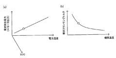
- (A) is an example of the relationship between battery remaining capacity, battery temperature, and output possible electric power
- (b) is an example of the relationship between engine temperature and required cranking torque.
- time fluctuations such as an engine speed concerning a comparative example.
- time fluctuations such as engine speed, concerning the embodiment of the present invention.
- FIG. 1 is a schematic diagram illustrating a configuration of a hybrid vehicle according to the present embodiment.
- FIG. 1 only members directly related to the present invention are shown, and other members are omitted as appropriate.
- a hybrid vehicle 1 includes an engine 11, a three-shaft power distribution mechanism 14 connected to a crankshaft 12 as an output shaft of the engine 11 via a damper 13, and a power distribution mechanism 14. Electric power can be supplied to the connected motor generator MG1 capable of generating electricity, the motor generator MG2 connected to the power distribution mechanism 14 via the transmission 15, and the motor generators MG1 and MG2.
- a battery 21 configured to be rechargeable by regenerative electric power of each of the generators MG1 and MG2 and an ECU (Electronic Control Unit: electronic control unit) 22 are configured.
- the engine 11 is an internal combustion engine that outputs power using fuel such as gasoline.
- the engine 11 receives operation control such as fuel injection control, ignition control, intake air amount adjustment control, and the like from the ECU 22.
- the power distribution mechanism 14 includes a sun gear 141, a ring gear 144 arranged concentrically with the sun gear 141, a plurality of pinion gears 142 that mesh with the sun gear 141 and also mesh with the ring gear 144, and the plurality of pinion gears 143 that rotate. And a carrier 143 that is held to revolve freely. That is, the power distribution mechanism 14 is configured as a planetary gear mechanism that performs differential action with the sun gear 141, the ring gear 144, and the carrier 143 as rotational elements.
- the sun gear 141 is connected to a motor / generator MG1.
- the crankshaft 12 of the engine 11 is connected to the carrier 143 via the damper 13.
- a transmission 15 is connected to the ring gear 144 via a ring gear shaft 144a.
- the power distribution mechanism 14 distributes the power from the engine 11 input from the carrier 143 to the sun gear 141 side and the ring gear 144 side according to the gear ratio.
- power distribution mechanism 14 integrates the power from engine 11 input from carrier 143 and the power from motor generator MG1 input from sun gear 141. Output to the ring gear 144 side. The power output to the ring gear 144 is output from the ring gear shaft 144a to the drive wheel 19 via the gear mechanism 17 and the differential gear 18.
- the transmission 15 is configured to be able to execute connection and release of the rotation shaft 16 of the motor / generator MG2 and the ring gear shaft 144a.
- the “motor / generator MG1” according to the present embodiment is an example of the “motor” according to the present invention.
- cranking torque control device When the motor / generator MG1 cranks the engine 11, the cranking torque control device 100 mounted on the hybrid vehicle 1 configured as described above varies the amount of power consumption caused by the rotational fluctuation of the engine 11.
- the ECU 22 is configured to correct the upper limit value of the output power of the battery 21 in accordance with the predicted fluctuation amount.
- the cranking torque control device 100 includes a voltage sensor 23 that detects a voltage between terminals of the battery 21, a current sensor 24 that detects a current input to and output from the battery 21, a temperature sensor 25 that detects a temperature of the battery 21, And a temperature sensor 26 for detecting the temperature of the engine 11.
- the “ECU 22” according to the present embodiment is an example of the “correction unit” according to the present invention. That is, in this embodiment, a part of the functions of the ECU 22 for various electronic controls of the hybrid vehicle 1 is used as a part of the cranking torque control device 100.
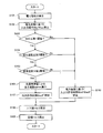
- cranking torque control process The cranking torque control process executed by the cranking torque control device 100 when the engine 11 is started (for example, when shifting from the EV traveling mode to the HV traveling mode) will be described with reference to the flowchart of FIG. To do.
- This cranking torque control process is repeatedly executed at predetermined time intervals (for example, every several milliseconds (milliseconds)) when the engine 11 is started.
- step S101 the ECU 22 as a part of the cranking torque control device 100 acquires the voltage across the terminals of the battery 21 detected by the voltage sensor 23 (step S101).
- the ECU 22 calculates input / output powers Win and Wout based on the state of the battery 21 (step S102). Specifically, for example, the ECU 22 is based on the remaining capacity (State of Charge: SOC) of the battery 21 specified by the acquired inter-terminal voltage of the battery 21, the temperature of the battery 21 detected by the temperature sensor 25, and the like. The input / output powers Win and Wout are calculated. The remaining capacity of the battery 21 may be specified by integrating the current value detected by the current sensor 24.
- SOC State of Charge
- the ECU 22 determines whether or not the engine 11 stays in the resonance band for a relatively long period due to the power that can be output from the battery 21. Specifically, the ECU 22 executes the following determination processes in steps S103 to S105. Note that the processing of steps S103 to S105 is not limited to the order described in FIG. 2, and may be executed from any processing.
- the ECU22 determines whether the remaining capacity of the battery 21 is below a 1st threshold value (step S103).
- the “first threshold value” is obtained experimentally, empirically, or by simulation, for example, by determining the relationship between the remaining capacity of the battery and the time spent for the engine speed exceeding the resonance band. Based on the obtained relationship, the remaining capacity of the battery may be set such that the time spent before exceeding the resonance band becomes the upper limit value of the allowable range.
- the ECU 22 determines whether the temperature of the battery 21 is equal to or lower than the second threshold (step S104).
- the “second threshold value” is, for example, (i) the temperature of the battery, (ii) the electric power that can be output by the battery, and (iii) the rotational speed of the engine, experimentally, empirically, or by simulation. Measures the relationship between the time spent to exceed the resonance band and the power that can be output based on the calculated relationship so that the time spent before exceeding the resonance band becomes the upper limit of the allowable range What is necessary is just to set as the temperature of the battery to perform.
- the ECU 22 determines that the engine temperature (here, the temperature of the engine 11 detected by the temperature sensor 26) is equal to or lower than the third threshold. It is determined whether or not there is (step S105).
- the “third threshold value” is, for example, (i) the engine temperature, (ii) the friction related to the engine, and (iii) the engine rotational speed, which are experimentally, empirically, or by simulation.
- the engine temperature corresponding to the friction may be set such that the time spent before exceeding the resonance band is the upper limit of the allowable range.
- step S105: Yes the ECU 22 It is determined that the engine 11 remains in the resonance band for a relatively long period due to the output power. Then, the ECU 22 calculates the output fluctuation spreso of the battery 21 caused by the rotation speed of the engine 11 staying in the resonance band (step S106).
- FIG. 3A is an example of the relationship between the remaining battery capacity, the battery temperature, and the output power
- FIG. 3B is an example of the relationship between the engine temperature and the required cranking torque. Note that the ECU 22 as a part of the cranking torque control device 100 stores the relationship shown in FIGS. 3A and 3B in advance as a map.
- ECU22 specifies the electric power which can be output of the battery 21 (proportional to the output torque of the motor generator MG1) based on the remaining capacity of the battery 21 and the temperature of the battery 21.
- the ECU 22 further specifies the required cranking torque based on the temperature of the engine 11.
- the ECU 22 specifies the target cranking rotational speed in consideration of the balance between the specified outputtable power corresponding to the output torque of the motor / generator MG1 and the specified required cranking torque.
- the ECU 22 uses, for example, the following equation to output the output fluctuation spreso as an example of the “fluctuation amount of power consumption caused by engine rotational fluctuation” according to the present invention. Is calculated.
- Output fluctuation spreso (Fluctuation upper limit rotational speed ⁇ Fluctuation lower limit rotational speed) ⁇ Torque ⁇ Circular ratio ⁇ 2
- the “variable upper limit rotational speed” and the “variable lower limit rotational speed” depend on the structure of the power transmission system of the hybrid vehicle 1 and can be predicted at the design stage. Yes.
- the ECU 22 calculates the output allowable limit Woutf ′ based on the output power Wout calculated in the process of step S102 and the output fluctuation spreso calculated in the process of step S106 (step S107). ). Specifically, for example, the ECU 22 calculates the output allowable limit Woutf ′ by subtracting the output fluctuation spreso from the output power Wout.
- the ECU 22 calculates the upper limit output torque (that is, the torque corresponding to the output allowable limit Woutf ′) and the lower limit output torque based on the calculated output allowable limit Woutf ′ (step S108). Subsequently, the ECU 22 calculates a target torque within the range of the upper limit output torque and the lower limit output torque (step S109).
- the ECU 22 determines that the rotational speed of the engine 11 does not stay in the resonance band. Then, the ECU 22 calculates the input / output allowable limits Winf and Woutf based on the power deviation (that is, the power consumption according to the torque of the motor / generator MG1 and the rotation speed of the engine 11 before a predetermined time) ( Step S110).
- the ECU 22 calculates an upper limit output torque and a lower limit output torque based on the calculated input / output allowable limits Winf, Woutf (step S108), and calculates a target torque (step S109).
- FIG. 4 is an example of time fluctuations such as the engine speed according to the comparative example
- FIG. 5 is an example of time fluctuations such as the engine speed according to the present embodiment.
- cranking torque control device executes only the output limitation of the battery 21 based on the power deviation.
- the ECU 22 tightens the output limit of the battery 21 at time t3 (see the second stage from the bottom in FIG. 4). Then, the cranking torque of the motor / generator MG1 decreases at time t4, which is delayed by a predetermined time from time t3 (see the lowermost stage in FIG. 4).
- the cranking torque control apparatus 100 when the engine 11 is predicted to stay in the resonance band when the engine 11 is started, as described above, the output fluctuation spreso is obtained from the output power Wout.
- the value obtained by subtracting only ie, the output allowable limit Woutf ′ is set as the upper limit output.
- cranking torque control apparatus 100 it is possible to suppress the occurrence of unexpected engine stall while preventing the voltage between the terminals of the battery 21 from falling below the lower limit voltage of the battery 21. .
- the broken line in FIG. 5 has shown time fluctuations, such as an engine speed which concerns on a comparative example.
- the present invention is not limited to the above-described embodiment, and can be appropriately changed without departing from the gist or concept of the invention that can be read from the claims and the entire specification, and cranking torque control with such a change is possible.
- the apparatus is also included in the technical scope of the present invention.
Landscapes
- Engineering & Computer Science (AREA)
- Chemical & Material Sciences (AREA)
- Combustion & Propulsion (AREA)
- Transportation (AREA)
- Mechanical Engineering (AREA)
- Automation & Control Theory (AREA)
- Electric Propulsion And Braking For Vehicles (AREA)
- Hybrid Electric Vehicles (AREA)
Abstract
Description
本実施形態に係るハイブリッド車両の構成について、図1を参照して説明する。図1は、本実施形態に係るハイブリッド車両の構成を示す概略図である。尚、図1では、本発明と直接関連のある部材のみを示し、その他の部材については適宜省略している。
以上のように構成されたハイブリッド車両1に搭載されるクランキングトルク制御装置100は、モータ・ジェネレータMG1がエンジン11をクランキングする際に、該エンジン11の回転変動に起因する消費電力の変動量を予測し、該予測された変動量に応じて、バッテリ21の出力可能電力の上限値を補正するECU22を備えて構成されている。
エンジン11が始動される際(例えば、EV走行モードからHV走行モードへ移行する際等)に、クランキングトルク制御装置100が実行するクランキングトルク制御処理について、図2のフローチャートを参照して説明する。このクランキングトルク制御処理は、エンジン11が始動される際に、所定時間毎(例えば、数msec(ミリ秒)毎)に繰り返し実行される。
出力変動spreso=(変動上限回転数-変動下限回転数)×トルク×円周率×2
尚、「変動上限回転数」及び「変動下限回転数」は、ハイブリッド車両1の動力伝達系の構造に依存するため、設計段階において予測可能であることが、本願発明者の研究により判明している。
Claims (1)
- エンジンと、前記エンジンに連結されると共に、前記エンジンをクランキング可能なモータと、前記モータに電力を供給可能なバッテリと、を備えるハイブリッド車両に搭載され、
前記モータが前記エンジンをクランキングする際に、前記エンジンの回転変動に起因する消費電力の変動量を予測し、前記予測された変動量に応じて、前記バッテリの出力可能電力の上限値を補正する補正手段を備える
ことを特徴とするクランキングトルク制御装置。
Priority Applications (4)
| Application Number | Priority Date | Filing Date | Title |
|---|---|---|---|
| JP2012520855A JP5273305B2 (ja) | 2011-05-18 | 2011-05-18 | クランキングトルク制御装置 |
| CN2011800309931A CN102958774A (zh) | 2011-05-18 | 2011-05-18 | 启动转矩控制装置 |
| PCT/JP2011/061408 WO2012157088A1 (ja) | 2011-05-18 | 2011-05-18 | クランキングトルク制御装置 |
| US13/520,309 US20130017926A1 (en) | 2011-05-18 | 2011-05-18 | Cranking torque control apparatus |
Applications Claiming Priority (1)
| Application Number | Priority Date | Filing Date | Title |
|---|---|---|---|
| PCT/JP2011/061408 WO2012157088A1 (ja) | 2011-05-18 | 2011-05-18 | クランキングトルク制御装置 |
Publications (1)
| Publication Number | Publication Date |
|---|---|
| WO2012157088A1 true WO2012157088A1 (ja) | 2012-11-22 |
Family
ID=47176452
Family Applications (1)
| Application Number | Title | Priority Date | Filing Date |
|---|---|---|---|
| PCT/JP2011/061408 Ceased WO2012157088A1 (ja) | 2011-05-18 | 2011-05-18 | クランキングトルク制御装置 |
Country Status (4)
| Country | Link |
|---|---|
| US (1) | US20130017926A1 (ja) |
| JP (1) | JP5273305B2 (ja) |
| CN (1) | CN102958774A (ja) |
| WO (1) | WO2012157088A1 (ja) |
Families Citing this family (7)
| Publication number | Priority date | Publication date | Assignee | Title |
|---|---|---|---|---|
| US8565956B2 (en) * | 2011-05-18 | 2013-10-22 | Toyota Jidosha Kabushiki Kaisha | Cranking torque control apparatus |
| DE102013207680A1 (de) * | 2013-04-26 | 2014-10-30 | Deere & Company | Betriebsstrategie für Hydbridfahrzeuge zur Realisierung einer Lastpunktverschiebung, einer Rekuperation und eines Boost |
| SE539028C2 (sv) | 2014-03-20 | 2017-03-21 | Scania Cv Ab | Förfarande för ivägkörning av ett fordon med en hybriddrivlina, fordon med en sådan hybriddrivlina, datorprogram för attstyra ivägkörning av ett fordon, samt en datorprogramproduk t innefattande programkod |
| SE539662C2 (sv) | 2014-03-20 | 2017-10-24 | Scania Cv Ab | Förfarande för att starta en förbränningsmotor i en hybriddrivlina, fordon med en sådan hybriddrivlina, datorprogram föratt starta en förbränningsmotor, samt en datorprogramproduk t innefattande programkod |
| SE540693C2 (sv) | 2014-03-20 | 2018-10-09 | Scania Cv Ab | Förfarande för att styra en hybriddrivlina, fordon med en sådan hybriddrivlina, datorprogram för att styra en sådan hybriddrivlina, samt en datorprogramprodukt innefattande programkod |
| SE538187C2 (sv) * | 2014-03-20 | 2016-03-29 | Scania Cv Ab | Förfarande för att styra en hybriddrivlina, fordon med en sådan hybriddrivlina, datorprogram för att styra en sådan hybriddrivlina, samt en datorprogramprodukt innefattande programkod |
| JP2016222100A (ja) * | 2015-05-29 | 2016-12-28 | スズキ株式会社 | 駆動制御システム |
Citations (4)
| Publication number | Priority date | Publication date | Assignee | Title |
|---|---|---|---|---|
| JP2001057704A (ja) * | 1999-08-09 | 2001-02-27 | Mazda Motor Corp | ハイブリッド車両の駆動装置 |
| JP2006094691A (ja) | 2004-08-25 | 2006-04-06 | Toyota Motor Corp | 動力出力装置およびこれを搭載する自動車並びに動力出力装置の制御方法 |
| JP2009166513A (ja) | 2008-01-10 | 2009-07-30 | Toyota Motor Corp | 電源装置およびその放電制御方法 |
| JP2009292179A (ja) * | 2008-06-02 | 2009-12-17 | Toyota Motor Corp | ハイブリッド自動車およびその制御方法 |
Family Cites Families (7)
| Publication number | Priority date | Publication date | Assignee | Title |
|---|---|---|---|---|
| JP4135681B2 (ja) * | 2004-06-02 | 2008-08-20 | トヨタ自動車株式会社 | 動力出力装置およびこれを搭載するハイブリッド車並びにこれらの制御方法 |
| JP2007168637A (ja) * | 2005-12-22 | 2007-07-05 | Toyota Motor Corp | 動力出力装置およびこれを搭載する車両並びに動力出力装置の制御方法 |
| US7722498B2 (en) * | 2006-06-21 | 2010-05-25 | Denso Corporation | Control device and method for hybrid electric vehicle |
| JP4229175B2 (ja) * | 2006-11-22 | 2009-02-25 | トヨタ自動車株式会社 | 動力出力装置、それを備えた自動車、および動力出力装置の制御方法 |
| JP4172523B1 (ja) * | 2007-04-24 | 2008-10-29 | トヨタ自動車株式会社 | 車両およびその制御方法 |
| JP4453746B2 (ja) * | 2007-11-21 | 2010-04-21 | トヨタ自動車株式会社 | 動力出力装置およびその制御方法並びに車両 |
| KR101085568B1 (ko) * | 2007-12-28 | 2011-11-25 | 아이신에이더블류 가부시키가이샤 | 회전전기 제어시스템 |
-
2011
- 2011-05-18 US US13/520,309 patent/US20130017926A1/en not_active Abandoned
- 2011-05-18 WO PCT/JP2011/061408 patent/WO2012157088A1/ja not_active Ceased
- 2011-05-18 CN CN2011800309931A patent/CN102958774A/zh active Pending
- 2011-05-18 JP JP2012520855A patent/JP5273305B2/ja not_active Expired - Fee Related
Patent Citations (4)
| Publication number | Priority date | Publication date | Assignee | Title |
|---|---|---|---|---|
| JP2001057704A (ja) * | 1999-08-09 | 2001-02-27 | Mazda Motor Corp | ハイブリッド車両の駆動装置 |
| JP2006094691A (ja) | 2004-08-25 | 2006-04-06 | Toyota Motor Corp | 動力出力装置およびこれを搭載する自動車並びに動力出力装置の制御方法 |
| JP2009166513A (ja) | 2008-01-10 | 2009-07-30 | Toyota Motor Corp | 電源装置およびその放電制御方法 |
| JP2009292179A (ja) * | 2008-06-02 | 2009-12-17 | Toyota Motor Corp | ハイブリッド自動車およびその制御方法 |
Also Published As
| Publication number | Publication date |
|---|---|
| JP5273305B2 (ja) | 2013-08-28 |
| JPWO2012157088A1 (ja) | 2014-07-31 |
| CN102958774A (zh) | 2013-03-06 |
| US20130017926A1 (en) | 2013-01-17 |
Similar Documents
| Publication | Publication Date | Title |
|---|---|---|
| JP5273305B2 (ja) | クランキングトルク制御装置 | |
| JP4450100B2 (ja) | 動力出力装置、それを備えた車両および動力出力装置の制御方法 | |
| US9604528B2 (en) | Control apparatus for hybrid vehicle | |
| JP5949906B2 (ja) | 車両の制御装置 | |
| JP5825129B2 (ja) | ハイブリッド車両の制御装置 | |
| JP5741153B2 (ja) | 充電制御装置 | |
| JP5459144B2 (ja) | ハイブリッド車 | |
| US20140058602A1 (en) | Hybrid vehicle | |
| JP2015128935A (ja) | ハイブリッド車両 | |
| JP7338531B2 (ja) | 車両の制御装置 | |
| JP2007168637A (ja) | 動力出力装置およびこれを搭載する車両並びに動力出力装置の制御方法 | |
| JP2010163061A (ja) | 動力出力装置、それを備えた車両および動力出力装置の制御方法 | |
| JP4876054B2 (ja) | 動力出力装置、それを備えた車両および動力出力装置の制御方法 | |
| JP5198398B2 (ja) | 動力出力装置およびハイブリッド車並びに下限蓄電割合更新方法 | |
| EP2957473B1 (en) | Hybrid vehicle | |
| WO2012039215A1 (ja) | 内燃機関の出力制御装置 | |
| JP5700362B2 (ja) | ハイブリッド車両 | |
| JPWO2012157089A1 (ja) | クランキングトルク制御装置 | |
| JP6740944B2 (ja) | ハイブリッド車両の制御装置 | |
| JP6409735B2 (ja) | ハイブリッド車の制御装置 | |
| JP2013126825A (ja) | 車両用制御装置 | |
| JP5077045B2 (ja) | 内燃機関の制御装置 | |
| JP2017206045A (ja) | 車両 | |
| JP2006296183A (ja) | 動力出力装置およびこれを搭載する自動車並びにハイブリッド車,動力出力装置の制御方法 | |
| JP5402838B2 (ja) | 電源装置および車両 |
Legal Events
| Date | Code | Title | Description |
|---|---|---|---|
| WWE | Wipo information: entry into national phase |
Ref document number: 201180030993.1 Country of ref document: CN |
|
| ENP | Entry into the national phase |
Ref document number: 2012520855 Country of ref document: JP Kind code of ref document: A |
|
| WWE | Wipo information: entry into national phase |
Ref document number: 2011849904 Country of ref document: EP |
|
| WWE | Wipo information: entry into national phase |
Ref document number: 13520309 Country of ref document: US |
|
| 121 | Ep: the epo has been informed by wipo that ep was designated in this application |
Ref document number: 11849904 Country of ref document: EP Kind code of ref document: A1 |
|
| NENP | Non-entry into the national phase |
Ref country code: DE |