WO2012153601A1 - 車体前部構造体 - Google Patents
車体前部構造体 Download PDFInfo
- Publication number
- WO2012153601A1 WO2012153601A1 PCT/JP2012/060206 JP2012060206W WO2012153601A1 WO 2012153601 A1 WO2012153601 A1 WO 2012153601A1 JP 2012060206 W JP2012060206 W JP 2012060206W WO 2012153601 A1 WO2012153601 A1 WO 2012153601A1
- Authority
- WO
- WIPO (PCT)
- Prior art keywords
- vehicle body
- extending
- body front
- stay
- front structure
- Prior art date
- Legal status (The legal status is an assumption and is not a legal conclusion. Google has not performed a legal analysis and makes no representation as to the accuracy of the status listed.)
- Ceased
Links
Images



Classifications
-
- B—PERFORMING OPERATIONS; TRANSPORTING
- B62—LAND VEHICLES FOR TRAVELLING OTHERWISE THAN ON RAILS
- B62D—MOTOR VEHICLES; TRAILERS
- B62D25/00—Superstructure or monocoque structure sub-units; Parts or details thereof not otherwise provided for
- B62D25/08—Front or rear portions
- B62D25/082—Engine compartments
- B62D25/085—Front-end modules
-
- B—PERFORMING OPERATIONS; TRANSPORTING
- B62—LAND VEHICLES FOR TRAVELLING OTHERWISE THAN ON RAILS
- B62D—MOTOR VEHICLES; TRAILERS
- B62D29/00—Superstructures, understructures, or sub-units thereof, characterised by the material thereof
- B62D29/04—Superstructures, understructures, or sub-units thereof, characterised by the material thereof predominantly of synthetic material
- B62D29/041—Understructures
Definitions
- the present invention relates to a vehicle body front structure, and more particularly to a vehicle body front structure that is relatively weak in the longitudinal direction of the vehicle and relatively strong in the vertical direction of the vehicle.
- a vehicle body front structure 101 as shown in FIG. 11, for example, is usually provided at the front of the vehicle body, particularly around the front side of the radiator.
- the vehicle body front structure 101 is connected to, for example, an upper 102 extending in the vehicle width direction at the upper portion of the structure 101, a lower 103 extending in the vehicle width direction at the lower portion, and both ends of the upper 102 and the lower 103 in the vehicle width direction. It has two sides 104 that extend in the direction, and an upper side 105 that extends from both ends of the upper 102 toward the rear of the vehicle body.
- Such a vehicle body front structure 101 may be required to have a relatively weak configuration in the longitudinal direction of the vehicle body in order to improve pedestrian protection performance in the event of a collision.
- the strength and rigidity in the longitudinal direction of the vehicle body corresponding to the height of the waist and thighs of the pedestrian are relatively weak from the viewpoint of more appropriately protecting the pedestrian.
- the vehicle body front structure 101 is often required to have a relatively strong configuration in the vertical direction of the vehicle body.
- the upper 102 is often provided with a hood locking structure, the strength and rigidity sufficient to withstand the load when the hood is strongly closed or the hood is flipped up are ensured. Is required.
- the vehicle body front structure 101 is also required to have a role for maintaining performance as a vehicle such as protection of a radiator, it is not preferable that the entire structure is too fragile, and the strength required for the vehicle body front, Stiffness must be ensured.
- Patent Document 1 discloses a structure in which pedestrian protection is achieved by forming the upper strength to be lower than the lower strength.
- the strength of the upper is weakened, there is a possibility that it cannot withstand the load in the vertical direction of the vehicle body as described above.
- Patent Document 2 discloses a structure in which a vertical member of a bulkhead (vehicle body front structure) is attached so as to be pivotable toward the rear of the vehicle, thereby absorbing a pedestrian's impact. .
- this structure requires a sufficient space for the bulkhead to rotate, it is difficult to apply to a vehicle in which space cannot be secured.
- Patent Document 3 discloses a structure that protects a pedestrian from an impact at the time of collision by integrating a metal impact relaxation member and a resin panel.
- a metal impact relaxation member and a resin panel.
- the metal impact mitigating member is a hollow member, it is a relatively large member, so that it is difficult to reduce the weight of the entire vehicle body front structure.
- the object of the present invention is to give the entire structure, in particular, the upper part, particularly high strength and rigidity sufficient to withstand loads that may be applied in the vertical direction of the vehicle body.
- the object of the present invention is to give the entire structure, in particular, the upper part, particularly high strength and rigidity sufficient to withstand loads that may be applied in the vertical direction of the vehicle body.
- to improve the pedestrian protection performance at the time of collision to provide a vehicle body front structure that can satisfy both the required performance in each direction, with reduced strength and rigidity in the longitudinal direction of the vehicle body
- it is to achieve this without increasing the installation space and without inhibiting the weight reduction of the vehicle body.
- a vehicle body front structure is a vehicle body front structure made of at least a fiber reinforced resin, and at least as a component of the structure, at least in the vehicle width direction.
- a vehicle body front having an upper that extends, a lower that extends in the vehicle width direction at the lower portion, two sides that are connected to both ends of the upper and the lower in the vehicle width direction and extend in the vertical direction, and an upper side that extends rearward from both ends of the upper
- at least one of a center stay that extends in the vertical direction and connects the upper and the lower and a side stay that extends in the oblique direction and connects the upper and the side is added to the added stay from the front of the vehicle body.
- the fragile part weakened rather than the other part of this stay with respect to the external force is provided.
- “consisting of at least a fiber reinforced resin” is basically composed of a fiber reinforced resin.
- a metal part or the like is attached or incorporated by insert molding. Means that it is possible.
- the upper side can extend from both ends of the upper portion to the rear of the vehicle body and be connected to the side members of the vehicle body, or can extend to the rear of the vehicle body without being connected to the side members.
- a center stay and a side stay is added, and these additional stays extend in the vertical direction of the vehicle body (the side stay is inclined in the vertical direction of the vehicle body).
- the side stay is inclined in the vertical direction of the vehicle body.
- it is in the form of a sticking rod, which increases the strength and rigidity of the vehicle body front structure in the vertical direction of the vehicle body.
- these additional stays are connected to the upper, the upper body's vertical strength and rigidity can be increased efficiently, and the upper can be sufficiently protected against loads during hood closure or crashing. It is possible to ensure sufficient strength and rigidity to withstand.
- the additional stay is provided with a weakened portion weaker than other parts (other parts of the additional stay) with respect to external force from the front of the vehicle body.
- the strength and rigidity in the longitudinal direction of the vehicle body are intentionally weakened at the fragile portion provided in the vehicle body front structure itself without being attached. Therefore, the pedestrian protection performance when a pedestrian collides with the front part of the vehicle body is effectively enhanced by the vehicle body front part structure itself made of at least fiber reinforced resin.
- the vehicle body front part structure itself made of at least fiber reinforced resin.
- the vehicle body front part structure which concerns on this invention consists of fiber reinforced resin fundamentally, it can comprise lightweight compared with the case where a large sized metal member is included. Furthermore, since the center stay and the additional stay of the side stay are both disposed within the frame of the conventional vehicle body front structure as shown in FIG. 11, a substantially new installation space is required. In addition, since there is no rotating portion, no space for rotating the member is required, and there is no disadvantage in terms of installation space, and the present invention can be easily implemented.
- the side may be provided with a fragile portion that is weaker than other parts of the side against an external force from the front of the vehicle. it can. If such a structure is adopted, the strength and rigidity in the longitudinal direction of the vehicle body are further reduced as the entire vehicle body front structure, and the pedestrian protection performance is further improved.
- the weakened portion is, for example, any one of thinning, notch installation, partial change of reinforcing fiber orientation state, intentional application of weld that is a collision part of resin flow during molding, or any combination thereof Can be configured.
- the fragile portion is provided so that the upper end of the fragile portion is located above the upper portion of the radiator.
- the radiator installed at the front part of the vehicle usually has a considerably high rigidity structurally, so if the radiator supports the impact load when it collides with a pedestrian, There is a risk that a large impact will be applied to the pedestrian via.
- the fragile portion above the radiator more precisely, by providing the upper end of the fragile portion at a position higher than the upper portion of the radiator, it is possible to reduce the impact force from the front of the vehicle body. When external force is applied, it becomes possible to bend only the upper structure part from the weak part to the rear, and it is possible to prevent the reaction force from the radiator from being directly transmitted to the pedestrian.
- the pedestrian protection performance as described above can be further improved.
- the type of the fiber reinforced resin constituting the vehicle body front structure according to the present invention is not particularly limited, and the reinforcing fiber may be carbon fiber and / or glass fiber, aramid fiber, or a reinforced fiber having a hybrid configuration combining these. Can be used.
- the use of carbon fiber is preferred from the viewpoint of ease of molding, strength and rigidity while ensuring weight reduction.
- the use of glass fiber is preferred.
- all of the reinforcing fibers do not have to be carbon fibers or glass fibers, and other fibers may be included. In particular, when carbon fiber is contained as part or as a whole of the fiber reinforced resin, it becomes possible to improve moldability, secure strength and rigidity, and reduce weight.
- the vehicle body front structure according to the present invention is preferably integrally molded by injection molding from the viewpoint of shortening the molding cycle and improving mass productivity.
- injection molding it is particularly preferable to use a thermoplastic resin for the matrix resin of the fiber reinforced resin constituting the structure.
- short fibers as the reinforcing fibers, so that the reinforcing fibers of the short fibers can be well injected into the mold together with the matrix resin.
- the vehicle body front structure by providing a specific additional stay and providing a weak portion on the additional stay itself, while ensuring the desired strength and rigidity in the vertical direction of the vehicle body, In the longitudinal direction of the vehicle body, the strength and rigidity can be appropriately reduced for pedestrian protection. These desirable performances can be satisfied without increasing the installation space and while reducing the weight of the vehicle body.
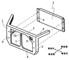
- FIG. 2 is a schematic perspective view which shows the structure of the vehicle body front part structure and radiator which concerns on one embodiment of this invention. It is a disassembled perspective view of the structure of FIG. It is the disassembled perspective view seen from the back side of the structure of FIG.
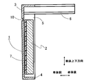
- FIG. 2 is an enlarged longitudinal sectional view taken along line AA of the structure of FIG.
- FIG. 2 is an enlarged longitudinal sectional view taken along line BB of the structure of FIG.
- FIG. 2 is an enlarged cross-sectional view taken along line CC of the structure of FIG.
- FIG. 1 It is a schematic sectional view showing an example of a fragile part configuration by partial change of the reinforcing fiber orientation state and an example of a fragile part configuration by intentional application of weld, (A) and (B) are views seen in cross sections orthogonal to each other is there. It is a schematic perspective view which shows the structure of the vehicle body front part structure which concerns on another embodiment of this invention. It is a schematic perspective view of the conventional vehicle body front structure.
- FIG. 1 to 6 show a vehicle body front structure 1 according to an embodiment of the present invention, and show an example of being disposed on the front side of a radiator 2.
- the vehicle body front structure 1 includes a vehicle body front structure made of at least a fiber reinforced resin.
- the vehicle body front structure 1 may be provided with a hood locking mechanism or other metal fittings, or may be provided by insert molding or the like, but the vehicle body front structure 1 shown in FIG. It shows only the part which consists of and is formed integrally.
- the vehicle body front structure 1 includes, as its components, an upper 3 that extends in the vehicle width direction (vehicle body left-right direction) at the top, a lower 4 that extends in the vehicle width direction at the bottom, and both ends of the upper 3 and the lower 4 in the vehicle width direction.
- Two sides 5 that are connected to each other and extend in the vertical direction, and upper sides 6 that extend rearward from the both ends of the upper 3 to the vehicle body.
- a center stay 7 that extends in the vertical direction and connects the upper 3 and the lower 4 at the center thereof and a side stay 8 that extends in the oblique direction and connects the upper 3 and the side 5 are added to the vehicle body front structure 1.
- the center stay 7 and the side stay 8 are also integrally formed with other parts.
- a radiator 2 is installed between the upper 3 and the lower 4 so as to be positioned between the both sides 5 immediately after the vehicle body front structure 1 configured as described above.
- Reference numeral 9 denotes a radiator mounting portion for mounting the radiator 2.
- At least one of the additional stays 7 and 8 (in this embodiment, all of the center stay 7 and both side stays 8) has a fragile portion 10 weakened by an external force from the front of the vehicle body as compared with other stay portions. Is provided. As shown in FIG. 4, the fragile portion 10 is provided such that the position of the upper end of the fragile portion 10 is higher than the upper portion of the radiator 2.
- the center stay 7 and the both side stays 8 while ensuring the desired strength and rigidity in the vertical direction of the vehicle body, in particular, while ensuring the desired strength and rigidity of the upper 3,
- the strength and rigidity of the vehicle body front structure 1 in the longitudinal direction of the vehicle body are appropriately weakened at the height position where the weak portions 10 are provided. And thereby improve the pedestrian protection performance at the time of collision.
- the fragile portion 10 so that the upper end of the fragile portion 10 is located above the upper portion of the radiator 2, the upper body front structure 1 from the fragile portion 10 can be moved without being obstructed by the radiator 2 in the event of a collision.
- the vehicle body front structure 1 is made of fiber reinforced resin, it is possible to achieve weight reduction while easily achieving necessary strength and rigidity as a whole. Furthermore, if the vehicle body front structure 1 is integrally formed by injection molding, it is possible to improve mass productivity while ensuring ease of molding.
- the fragile portion 10 is any one of the following: thinning, notch installation, partial modification of reinforcing fiber orientation state, intentional application of weld which is a collision portion of resin flow during molding, or any of these It is possible to comprise by the combination of.
- the weakened portion 10a can be provided in the longitudinal direction of the vehicle body by partially thinning the center stay 7 made of fiber reinforced resin.
- a weak fragile portion 10b is provided in the longitudinal direction of the vehicle body. Can do.
- the weak fragile portion 10c can be provided in the longitudinal direction of the vehicle body.
- the degree of reinforcement by the reinforcing fiber 11 can be weakened at the fragile portion 10c.
- the weld portion can be configured as a weak portion 10c that is weak in the longitudinal direction of the vehicle body.
- the resin flow from both sides at the time of injection molding collides and the orientation direction of the reinforcing fibers 11 is from the vertical direction of the vehicle body along the direction of the collided resin flow.
- the vehicle body is changed by approximately 90 degrees in the left-right direction.
- the strength and rigidity in the vertical direction of the vehicle body are increased.
- the strength and rigidity in the longitudinal direction of the vehicle body are weakened.
- FIG. 10 shows an example in which the fragile portion 20 is provided on the side body 5 on both sides of the vehicle body front structure 1 shown in FIG.
- the fragile portions 20 are provided on both sides 5, but the fragile portions 20 may be provided only on either the left or right side 5.
- the vehicle body front structure according to the present invention can be applied to any vehicle body that requires improvement in pedestrian protection performance at the time of collision.
Landscapes
- Engineering & Computer Science (AREA)
- Chemical & Material Sciences (AREA)
- Combustion & Propulsion (AREA)
- Transportation (AREA)
- Mechanical Engineering (AREA)
- Architecture (AREA)
- Structural Engineering (AREA)
- Body Structure For Vehicles (AREA)
Abstract
少なくとも繊維強化樹脂からなる車体の前部構造体であって、構造体の構成要素として、少なくとも、上部で車幅方向に延びるアッパと、下部で車幅方向に延びるロアと、アッパとロアの車幅方向両端に接続され上下方向に延びる2つのサイドと、アッパの両端部から車体後方に延びるアッパサイドとを有する構造体において、上下方向に延びアッパとロアを連結するセンターステーおよび斜め方向に延びアッパとサイドを連結するサイドステーの少なくとも一つが付加されており、該付加されたステーに、車体前方からの外力に対し該ステーの他の部位よりも弱められた脆弱部が設けられている車体前部構造体。付加ステー自体に脆弱部を設けることにより、車体上下方向については望ましい強度、剛性を確保しつつ、車体前後方向については歩行者保護のために適切に強度、剛性を弱めることができる。
Description
本発明は、車体前部構造体に関し、とくに、車体前後方向には比較的弱く車体上下方向には比較的強くした車体前部構造体に関する。
車体前部には、とくにラジエータの前面側周囲には、通常、例えば図11に示すような車体前部構造体101が設けられる。車体前部構造体101は、例えば、構造体101の上部で車幅方向に延びるアッパ102と、下部で車幅方向に延びるロア103と、アッパ102とロア103の車幅方向両端に接続され上下方向に延びる2つのサイド104と、アッパ102の両端部から車体後方に延びるアッパサイド105とを有している。
このような車体前部構造体101には、衝突時の歩行者保護性能を高めるために、車体前後方向には比較的弱い構成が求められることがある。とくに、歩行者の腰部や大腿部の高さに相当する部位の車体前後方向の強度、剛性が比較的弱いことが、歩行者をより適切に保護できる観点から好ましい。一方で、車体前部構造体101には、車体上下方向に比較的強い構成が求められることが多い。とくに上記アッパ102には、フードの係止構造部が設けられることが多いので、フードの強閉や衝突時の跳ね上げ等の際の荷重に対し十分に耐え得るだけの強度、剛性を確保することが求められる。また、車体前部構造体101には、ラジエータの保護等の車両としての性能維持のための役割も求められることから、構造体全体として脆弱すぎるものは好ましくなく、車体前部に必要な強度、剛性は確保されなければならない。
このような要求性能に鑑み、とくに歩行者保護性能を高めるために、従来から種々の提案がなされている。例えば、特許文献1には、アッパの強度がロアの強度よりも弱く形成されることにより、歩行者保護を図るようにした構造が開示されている。しかし、アッパの強度を弱くした場合、上述したような車体上下方向の荷重に耐えられない可能性がある。
また、特許文献2には、バルクヘッド(車体前部構造体)の縦部材が、車両後方へ回動可能に取り付けられることにより、歩行者の衝撃を吸収するようにした構造が開示されている。しかし、この構造では、バルクヘッドが回動できるだけの十分なスペースが必要となるため、スペースが確保できない車両には適用が難しい。
さらに、特許文献3には、金属製の衝撃緩和部材と樹脂製のパネルを一体化することにより歩行者を衝突時の衝撃から保護するようにした構造が開示されている。しかし、この構造では、金属製の衝撃緩和部材と樹脂製のパネルを一体化させなければならないため、作製のための作業工数が増加するという問題がある。また、金属製の衝撃緩和部材は中空の部材とはされているものの、比較的大型の部材となるため、車体前部構造体全体としての軽量化は難しい構造となっている。
そこで本発明の課題は、上記のような現状に鑑み、構造体全体として、とくにアッパに、車体上下方向に負荷される可能性のある荷重に耐え得るだけの十分に高い強度、剛性を持たせつつ、衝突時の歩行者保護性能を高めるために、車体前後方向には強度、剛性を弱めた、それぞれの方向への要求性能をともに満たすことが可能な車体前部構造体を提供することにあり、しかも、それを、設置スペースを増大させることなく、かつ、車体の軽量化を阻害することなく達成することにある。
上記課題を解決するために、本発明に係る車体前部構造体は、少なくとも繊維強化樹脂からなる車体の前部構造体であって、構造体の構成要素として、少なくとも、上部で車幅方向に延びるアッパと、下部で車幅方向に延びるロアと、アッパとロアの車幅方向両端に接続され上下方向に延びる2つのサイドと、アッパの両端部から車体後方に延びるアッパサイドとを有する車体前部構造体において、上下方向に延びアッパとロアを連結するセンターステーおよび斜め方向に延びアッパとサイドを連結するサイドステーの少なくとも一つが付加されており、該付加されたステーに、車体前方からの外力に対し該ステーの他の部位よりも弱められた脆弱部が設けられていることを特徴とするものからなる。ここで「少なくとも繊維強化樹脂からなる」とは、基本的には繊維強化樹脂で構成されるが、他の部材との取付等のために、金属部品等を取り付けたり、インサート成形により組み込んだりすることが可能であることを意味している。また、上記アッパサイドは、アッパの両端部から車体後方に延びて車体のサイドメンバと接続されることも可能であるし、サイドメンバとは接続されずに車体後方に延びることも可能である。
このような本発明に係る車体前部構造体においては、センターステーおよびサイドステーの少なくとも一つが付加されており、これら付加ステーは車体上下方向に延びることになるので(サイドステーは斜めに車体上下方向に延びる)、車体上下方向に関しては突っかい棒の形態をなし、車体前部構造体の車体上下方向の強度、剛性が高められる。とくにこれら付加ステーはアッパに連結されているので、アッパの車体上下方向の強度、剛性が効率よく高められ、アッパに関して、フードの強閉や衝突時の跳ね上げ等の際の荷重に対し十分に耐え得るだけの強度、剛性を確保することが可能になる。そして、上記付加ステーには、車体前方からの外力に対し他の部位(付加ステーの他の部位)よりも弱められた脆弱部が設けられているので、この脆弱部にて、つまり緩衝部材などを付設することなく車体前部構造体自体に設けられた脆弱部にて、車体前後方向の強度、剛性が意図的に弱められることになる。したがって、車体前部に歩行者が衝突した際の歩行者保護性能が、少なくとも繊維強化樹脂からなる車体前部構造体自体にて効果的に高められることになる。その結果、この車体前部構造体においては、車体上下方向には必要な強度、剛性が確保されつつ、車体前後方向には強度、剛性が弱められて歩行者保護性能が向上され、各方向に対する要求性能がともに満たされる。しかも、本発明に係る車体前部構造体は基本的に繊維強化樹脂からなるので、大型の金属部材を含む場合に比べ軽量に構成できる。さらに、上記センターステーおよびサイドステーの付加ステーは、ともに図11に示したような従来の車体前部構造体の枠内に配置されるものであるから、実質的に新たな設置スペースは要求されず、かつ、回動部分は皆無であるから、部材回動用スペースも不要であり、設置スペース的な不利は発生せず、本発明は容易に実施できる。
上記本発明に係る車体前部構造体においては、さらに、上記サイドにも、車体前方からの外力に対し該サイドの他の部位よりも弱められた脆弱部が設けられている構造とすることができる。このような構造を採用すれば、車体前部構造体全体としてさらに車体前後方向の強度、剛性が弱められ、歩行者保護性能が一層向上される。
また、上記脆弱部は、例えば、薄肉化、切欠設置、強化繊維配向状態の部分的変更、成形時の樹脂流れの衝突部であるウエルドの意図的付与のいずれか、またはこれらのいずれかの組み合わせによって構成することができる。いずれの形態であっても、その部位にて、車体前後方向の強度、剛性に的を絞って意図的に弱めることが可能である。
また、上記脆弱部は、その上端がラジエータの上部以上の位置になるように設けられていることが好ましい。すなわち、車両の前部に設置されるラジエータは、通常、構造的に相当高い剛性を有しているので、歩行者に衝突した際にラジエータが衝撃荷重を支えてしまうと、車体前部構造体を介して歩行者に大きな衝撃が加わるおそれがある。しかし、脆弱部をラジエータに対して上位に設けておくことにより、より正確には、脆弱部の上端がラジエータの上部以上の位置になるように設けておくことにより、車体前方から衝撃力等の外力が加わった際に、脆弱部から上部の構造体部分のみを後方へ折れ曲がらせることが可能になり、ラジエータからの反力が直接的に歩行者に伝達されないようにすることが可能になり、上述したような歩行者保護性能のさらなる向上が可能となる。
本発明に係る車体前部構造体を構成する繊維強化樹脂の種類はとくに限定されず、強化繊維としても、炭素繊維および/またはガラス繊維、アラミド繊維、さらにはこれらを組み合わせたハイブリッド構成の強化繊維の使用が可能である。成形のし易さ、強度、剛性を確保しながら軽量化できる点などからは、炭素繊維の使用が好ましく、成形のし易さに加え、安価である点を考慮すると、ガラス繊維の使用が好ましい。ただし、強化繊維の全部が炭素繊維やガラス繊維である必要はなく、他の繊維が含まれていてもよい。とくに、繊維強化樹脂の強化繊維の一部としてあるいは全体として炭素繊維が含まれていると、成形性の向上や、強度、剛性の確保、軽量化が可能になる。
また、本発明に係る車体前部構造体は、成形サイクルの短縮、量産性の向上等の面から、射出成形により全体が一体成形されていることが好ましい。射出成形とする場合には、構造体を構成する繊維強化樹脂のマトリックス樹脂には、とくに熱可塑性樹脂を使用すると良い。また、強化繊維としては、短繊維を使用することが好ましく、それによって短繊維の強化繊維をマトリックス樹脂とともに良好に成形型内に射出できるようになる。
このように、本発明に係る車体前部構造体によれば、特定の付加ステーを設け、その付加ステー自体に脆弱部を設けることにより、車体上下方向については望ましい強度、剛性を確保しつつ、車体前後方向については歩行者保護のために適切に強度、剛性を弱めることができる。そして、これらの望ましい性能を、設置スペースを増大させることなく、かつ、車体の軽量化をはかりつつ、満たすことが可能になる。
以下に、本発明の望ましい実施の形態を、図面を参照しながら説明する。
図1~図6は、本発明の一実施態様に係る車体前部構造体1を示しており、ラジエータ2の前面側に配置された例を示している。車体前部構造体1は、少なくとも繊維強化樹脂からなる車体の前部構造体からなる。この車体前部構造体1には、フードの係止機構や他の金具などが付設されたり、インサート成形等によって設けられてもよいが、図示した車体前部構造体1は、繊維強化樹脂のみからなり、全体が一体成形された部分のみを示している。車体前部構造体1は、その構成要素として、上部で車幅方向(車体左右方向)に延びるアッパ3と、下部で車幅方向に延びるロア4と、アッパ3とロア4の車幅方向両端に接続され上下方向に延びる2つのサイド5と、アッパ3の両端部から車体後方に延びるアッパサイド6とを有している。この車体前部構造体1に、上下方向に延びアッパ3とロア4をそれらの中央部で連結するセンターステー7と、斜め方向に延びアッパ3とサイド5を連結するサイドステー8が付加されており、これらセンターステー7とサイドステー8も他の部分とともに一体成形されている。このように構成された車体前部構造体1の直後方に、ラジエータ2が、アッパ3とロア4間で両サイド5間に位置するように設置されている。符号9は、このラジエータ2を取り付けるためのラジエータ取付部を示している。
図1~図6は、本発明の一実施態様に係る車体前部構造体1を示しており、ラジエータ2の前面側に配置された例を示している。車体前部構造体1は、少なくとも繊維強化樹脂からなる車体の前部構造体からなる。この車体前部構造体1には、フードの係止機構や他の金具などが付設されたり、インサート成形等によって設けられてもよいが、図示した車体前部構造体1は、繊維強化樹脂のみからなり、全体が一体成形された部分のみを示している。車体前部構造体1は、その構成要素として、上部で車幅方向(車体左右方向)に延びるアッパ3と、下部で車幅方向に延びるロア4と、アッパ3とロア4の車幅方向両端に接続され上下方向に延びる2つのサイド5と、アッパ3の両端部から車体後方に延びるアッパサイド6とを有している。この車体前部構造体1に、上下方向に延びアッパ3とロア4をそれらの中央部で連結するセンターステー7と、斜め方向に延びアッパ3とサイド5を連結するサイドステー8が付加されており、これらセンターステー7とサイドステー8も他の部分とともに一体成形されている。このように構成された車体前部構造体1の直後方に、ラジエータ2が、アッパ3とロア4間で両サイド5間に位置するように設置されている。符号9は、このラジエータ2を取り付けるためのラジエータ取付部を示している。
上記付加ステー7,8の少なくとも一つに(本実施態様では、センターステー7と両サイドステー8の全てに)、車体前方からの外力に対し他のステー部位よりも弱められた脆弱部10が設けられている。脆弱部10は、図4に示すように、脆弱部10の上端の位置がラジエータ2の上部以上の位置になるように設けられている。
このように、センターステー7と両サイドステー8を設けることにより車体上下方向には望ましい強度、剛性を確保しつつ、とくにアッパ3の望ましい強度、剛性を確保しつつ、車体前部構造体1の上部側にてセンターステー7と両サイドステー8に脆弱部10を設けることにより、それら脆弱部10を設けた高さ位置で車体前部構造体1の車体前後方向における強度、剛性を適切に弱めることができ、それによって衝突時の歩行者保護性能を向上することができる。とくに脆弱部10をその上端の位置がラジエータ2の上部以上の位置になるように設けることで、衝突時にラジエータ2に阻害されることなく、脆弱部10から上位の車体前部構造体1部分を下位の部分に対して円滑に折れ曲がらせることが可能になり、より適切に歩行者を保護することが可能になる。また、センターステー7と両サイドステー8は、アッパ3、ロア4、サイド5に囲まれた領域の範囲内に設けられるので、これらステーを設置するための特別なスペースは実質的に不要である。また、車体前部構造体1は繊維強化樹脂からなるので、全体として容易に必要な強度、剛性を達成しつつ、軽量化をはかることができる。さらに、この車体前部構造体1を射出成形により一体成形すれば、成形の容易性を確保しつつ、量産性の向上が可能になる。
上記脆弱部10は、以下のように、薄肉化、切欠設置、強化繊維配向状態の部分的変更、成形時の樹脂流れの衝突部であるウエルドの意図的付与のいずれか、またはこれらのいずれかの組み合わせによって構成することが可能である。
例えば、センターステー7に脆弱部10を設ける場合の一例を図7に示すように(サイドステー8についても同様に設けることができる。以下の各種形態についても同じである。)、例えばラジエータ2よりも上部の位置において、繊維強化樹脂からなるセンターステー7を部分的に薄肉化することにより、車体前後方向に弱い脆弱部10aを設けることができる。
また、図8に示すように、繊維強化樹脂からなるセンターステー7の特定部位に切欠10b(図示例では、V字状の切欠)を設けることにより、車体前後方向に弱い脆弱部10bを設けることができる。
また、図9(A)、(B)に示すように、繊維強化樹脂からなるセンターステー7の特定部位において、強化繊維配向状態を部分的に変更することにより(配向方向にばらつきを持たせることにより)、および/または、強化繊維11の配置密度を意図的に変更することにより(例えば、意図的に低下させることにより)、車体前後方向に弱い脆弱部10cを設けることができる。
例えば、強化繊維11の配向を部分的に変更させると、脆弱部10cで強化繊維11による強化度合を弱めることができる。図9(A)、(B)に示すような状態を実現するための具体的手段の一例として、繊維強化樹脂からなるセンターステー7の特定部位において、成形時の樹脂流れの衝突部であるウエルドを意図的に付与することが挙げられ、このウエルド部分を車体前後方向に弱い脆弱部10cとして構成することができる。図示例では、脆弱部10cを構成するウエルド部分において、例えば射出成形時の両側からの樹脂流れが衝突し、衝突した樹脂流れの方向に沿って、強化繊維11の配向方向が、車体上下方向から車体左右方向へとほぼ90度変更されている。強化繊維11が車体上下方向に配向されている部分では車体上下方向の強度、剛性が高められているが、ほぼ90度変更されて強化繊維11が車体左右方向に配向された脆弱部10c(ウエルド部分)では、車体前後方向の強度、剛性が弱められている。
なお、前述の図1に示した実施態様では、脆弱部10をセンターステー7と両サイドステー8に設けた例を示したが、さらに、サイド5にも、車体前方からの外力に対し該サイド5の他の部位よりも弱められた脆弱部を設けることができる。例えば、図10に、図1に示した車体前部構造体1に、さらに、両側のサイド5にも脆弱部20を設けた例を示す。このような脆弱部20を追加して設けることにより、車体前部構造体1全体としてさらに車体前後方向の強度、剛性を弱めることができ、歩行者保護性能を一層向上することが可能になる。図示例では、両側のサイド5にそれぞれ脆弱部20を設けたが、脆弱部20は、左右いずれか一方のサイド5のみに設けることも可能である。
本発明に係る車体前部構造体は、衝突時の歩行者保護性能の向上が求められる、あらゆる車体に適用可能である。
1:車体前部構造体
2:ラジエータ
3:アッパ
4:ロア
5:サイド
6:アッパサイド
7:センターステー
8:サイドステー
9:ラジエータ取付部
10、10a、10b、10c、20:脆弱部
11:強化繊維
2:ラジエータ
3:アッパ
4:ロア
5:サイド
6:アッパサイド
7:センターステー
8:サイドステー
9:ラジエータ取付部
10、10a、10b、10c、20:脆弱部
11:強化繊維
Claims (6)
- 少なくとも繊維強化樹脂からなる車体の前部構造体であって、構造体の構成要素として、少なくとも、上部で車幅方向に延びるアッパと、下部で車幅方向に延びるロアと、アッパとロアの車幅方向両端に接続され上下方向に延びる2つのサイドと、アッパの両端部から車体後方に延びるアッパサイドとを有する車体前部構造体において、上下方向に延びアッパとロアを連結するセンターステーおよび斜め方向に延びアッパとサイドを連結するサイドステーの少なくとも一つが付加されており、該付加されたステーに、車体前方からの外力に対し該ステーの他の部位よりも弱められた脆弱部が設けられていることを特徴とする車体前部構造体。
- さらに、前記サイドにも、車体前方からの外力に対し該サイドの他の部位よりも弱められた脆弱部が設けられている、請求項1に記載の車体前部構造体。
- 前記脆弱部が、薄肉化、切欠設置、強化繊維配向状態の部分的変更、成形時の樹脂流れの衝突部であるウエルドの意図的付与のいずれか、またはこれらのいずれかの組み合わせによって構成されている、請求項1または2に記載の車体前部構造体。
- 前記脆弱部が、その上端がラジエータの上部以上の位置になるように設けられている、請求項1~3のいずれかに記載の車体前部構造体。
- 前記繊維強化樹脂の強化繊維として炭素繊維および/またはガラス繊維が含まれている、請求項1~4のいずれかに記載の車体前部構造体。
- 射出成形により全体が一体成形されている、請求項1~5のいずれかに記載の車体前部構造体。
Priority Applications (1)
| Application Number | Priority Date | Filing Date | Title |
|---|---|---|---|
| JP2012540211A JPWO2012153601A1 (ja) | 2011-05-11 | 2012-04-16 | 車体前部構造体 |
Applications Claiming Priority (2)
| Application Number | Priority Date | Filing Date | Title |
|---|---|---|---|
| JP2011-106052 | 2011-05-11 | ||
| JP2011106052 | 2011-05-11 |
Publications (1)
| Publication Number | Publication Date |
|---|---|
| WO2012153601A1 true WO2012153601A1 (ja) | 2012-11-15 |
Family
ID=47139087
Family Applications (1)
| Application Number | Title | Priority Date | Filing Date |
|---|---|---|---|
| PCT/JP2012/060206 Ceased WO2012153601A1 (ja) | 2011-05-11 | 2012-04-16 | 車体前部構造体 |
Country Status (2)
| Country | Link |
|---|---|
| JP (1) | JPWO2012153601A1 (ja) |
| WO (1) | WO2012153601A1 (ja) |
Cited By (2)
| Publication number | Priority date | Publication date | Assignee | Title |
|---|---|---|---|---|
| JP2018100055A (ja) * | 2016-12-21 | 2018-06-28 | トヨタ自動車株式会社 | エネルギ吸収構造 |
| FR3093048A1 (fr) * | 2019-02-27 | 2020-08-28 | Renault S.A.S | Dispositif de protection pour un véhicule automobile. |
Citations (6)
| Publication number | Priority date | Publication date | Assignee | Title |
|---|---|---|---|---|
| JPH03128574U (ja) * | 1990-04-09 | 1991-12-25 | ||
| JPH11152062A (ja) * | 1997-11-19 | 1999-06-08 | Idemitsu Petrochem Co Ltd | 自動車用フロントエンド |
| JP2003335263A (ja) * | 2002-03-11 | 2003-11-25 | Denso Corp | 車両の前端構造 |
| JP2004098814A (ja) * | 2002-09-09 | 2004-04-02 | Fuji Heavy Ind Ltd | 車両の熱交換器取付構造 |
| JP2004123023A (ja) * | 2002-10-04 | 2004-04-22 | Calsonic Kansei Corp | 車両用ラジエータコアサポート及びその製造方法 |
| JP2008149772A (ja) * | 2006-12-14 | 2008-07-03 | Mitsubishi Automob Eng Co Ltd | 車両前部の車体構造 |
-
2012
- 2012-04-16 WO PCT/JP2012/060206 patent/WO2012153601A1/ja not_active Ceased
- 2012-04-16 JP JP2012540211A patent/JPWO2012153601A1/ja active Pending
Patent Citations (6)
| Publication number | Priority date | Publication date | Assignee | Title |
|---|---|---|---|---|
| JPH03128574U (ja) * | 1990-04-09 | 1991-12-25 | ||
| JPH11152062A (ja) * | 1997-11-19 | 1999-06-08 | Idemitsu Petrochem Co Ltd | 自動車用フロントエンド |
| JP2003335263A (ja) * | 2002-03-11 | 2003-11-25 | Denso Corp | 車両の前端構造 |
| JP2004098814A (ja) * | 2002-09-09 | 2004-04-02 | Fuji Heavy Ind Ltd | 車両の熱交換器取付構造 |
| JP2004123023A (ja) * | 2002-10-04 | 2004-04-22 | Calsonic Kansei Corp | 車両用ラジエータコアサポート及びその製造方法 |
| JP2008149772A (ja) * | 2006-12-14 | 2008-07-03 | Mitsubishi Automob Eng Co Ltd | 車両前部の車体構造 |
Cited By (4)
| Publication number | Priority date | Publication date | Assignee | Title |
|---|---|---|---|---|
| JP2018100055A (ja) * | 2016-12-21 | 2018-06-28 | トヨタ自動車株式会社 | エネルギ吸収構造 |
| CN108327669A (zh) * | 2016-12-21 | 2018-07-27 | 丰田自动车株式会社 | 能量吸收结构 |
| FR3093048A1 (fr) * | 2019-02-27 | 2020-08-28 | Renault S.A.S | Dispositif de protection pour un véhicule automobile. |
| EP3702222A1 (fr) * | 2019-02-27 | 2020-09-02 | Renault S.A.S. | Dispositif de protection pour un véhicule automobile |
Also Published As
| Publication number | Publication date |
|---|---|
| JPWO2012153601A1 (ja) | 2014-07-31 |
Similar Documents
| Publication | Publication Date | Title |
|---|---|---|
| CN106956721B (zh) | 车身结构 | |
| JP6252507B2 (ja) | 車両用外装部材及び車両のバックドア | |
| JP5862555B2 (ja) | 自動車の車体構造 | |
| JP6187537B2 (ja) | 車両の上部車体構造 | |
| US8075048B2 (en) | Bonnet for automobile having automobiles that protects the heads of pedestrians | |
| JP6299486B2 (ja) | 車体前部構造 | |
| JP5978133B2 (ja) | 車体前部構造体 | |
| JP2008221985A (ja) | バンパリインフォースメント支持構造 | |
| JP6247753B2 (ja) | 繊維強化材料からなる補強部材を有する自動車のアクスルキャリア | |
| JP2005178682A (ja) | 自動車の車体前部構造 | |
| KR20150007313A (ko) | 차량용 시트 쿠션 프레임 및 그의 제조 방법 | |
| JP6187772B2 (ja) | 車体の補強構造 | |
| CN104044646B (zh) | 车体后部构造 | |
| JPWO2012153601A1 (ja) | 車体前部構造体 | |
| JP2008149895A (ja) | フレーム構造体 | |
| KR102457625B1 (ko) | 자동차 몸체 구조물용 보강재 | |
| JP2005231618A (ja) | 自動車用外板部材 | |
| KR101092770B1 (ko) | 프런트사이드멤버 보강구조 | |
| JP4616015B2 (ja) | 三角窓補強構造 | |
| JP6108195B2 (ja) | シートバックフレーム | |
| KR101220005B1 (ko) | 엔진룸 보강 구조 | |
| JP2016124436A (ja) | 車両のフロアアンダーカバー | |
| US9840285B2 (en) | Front vehicle body and method of fabricating front vehicle body | |
| JP2006306363A (ja) | 自動車用ボンネット | |
| JP2012240528A (ja) | 車両衝撃吸収構造 |
Legal Events
| Date | Code | Title | Description |
|---|---|---|---|
| ENP | Entry into the national phase |
Ref document number: 2012540211 Country of ref document: JP Kind code of ref document: A |
|
| 121 | Ep: the epo has been informed by wipo that ep was designated in this application |
Ref document number: 12782482 Country of ref document: EP Kind code of ref document: A1 |
|
| NENP | Non-entry into the national phase |
Ref country code: DE |
|
| 122 | Ep: pct application non-entry in european phase |
Ref document number: 12782482 Country of ref document: EP Kind code of ref document: A1 |