WO2012153505A1 - 変倍光学系および撮像装置 - Google Patents
変倍光学系および撮像装置 Download PDFInfo
- Publication number
- WO2012153505A1 WO2012153505A1 PCT/JP2012/002983 JP2012002983W WO2012153505A1 WO 2012153505 A1 WO2012153505 A1 WO 2012153505A1 JP 2012002983 W JP2012002983 W JP 2012002983W WO 2012153505 A1 WO2012153505 A1 WO 2012153505A1
- Authority
- WO
- WIPO (PCT)
- Prior art keywords
- lens
- lens group
- cemented
- optical system
- positive
- Prior art date
- Legal status (The legal status is an assumption and is not a legal conclusion. Google has not performed a legal analysis and makes no representation as to the accuracy of the status listed.)
- Ceased
Links
Images







Classifications
-
- G—PHYSICS
- G02—OPTICS
- G02B—OPTICAL ELEMENTS, SYSTEMS OR APPARATUS
- G02B13/00—Optical objectives specially designed for the purposes specified below
- G02B13/04—Reversed telephoto objectives
-
- G—PHYSICS
- G02—OPTICS
- G02B—OPTICAL ELEMENTS, SYSTEMS OR APPARATUS
- G02B15/00—Optical objectives with means for varying the magnification
- G02B15/14—Optical objectives with means for varying the magnification by axial movement of one or more lenses or groups of lenses relative to the image plane for continuously varying the equivalent focal length of the objective
- G02B15/143—Optical objectives with means for varying the magnification by axial movement of one or more lenses or groups of lenses relative to the image plane for continuously varying the equivalent focal length of the objective having three groups only
- G02B15/1435—Optical objectives with means for varying the magnification by axial movement of one or more lenses or groups of lenses relative to the image plane for continuously varying the equivalent focal length of the objective having three groups only the first group being negative
- G02B15/143507—Optical objectives with means for varying the magnification by axial movement of one or more lenses or groups of lenses relative to the image plane for continuously varying the equivalent focal length of the objective having three groups only the first group being negative arranged -++
-
- G—PHYSICS
- G02—OPTICS
- G02B—OPTICAL ELEMENTS, SYSTEMS OR APPARATUS
- G02B13/00—Optical objectives specially designed for the purposes specified below
- G02B13/14—Optical objectives specially designed for the purposes specified below for use with infrared or ultraviolet radiation
-
- G—PHYSICS
- G02—OPTICS
- G02B—OPTICAL ELEMENTS, SYSTEMS OR APPARATUS
- G02B13/00—Optical objectives specially designed for the purposes specified below
- G02B13/18—Optical objectives specially designed for the purposes specified below with lenses having one or more non-spherical faces, e.g. for reducing geometrical aberration
-
- G—PHYSICS
- G02—OPTICS
- G02B—OPTICAL ELEMENTS, SYSTEMS OR APPARATUS
- G02B15/00—Optical objectives with means for varying the magnification
- G02B15/14—Optical objectives with means for varying the magnification by axial movement of one or more lenses or groups of lenses relative to the image plane for continuously varying the equivalent focal length of the objective
- G02B15/16—Optical objectives with means for varying the magnification by axial movement of one or more lenses or groups of lenses relative to the image plane for continuously varying the equivalent focal length of the objective with interdependent non-linearly related movements between one lens or lens group, and another lens or lens group
- G02B15/177—Optical objectives with means for varying the magnification by axial movement of one or more lenses or groups of lenses relative to the image plane for continuously varying the equivalent focal length of the objective with interdependent non-linearly related movements between one lens or lens group, and another lens or lens group having a negative front lens or group of lenses
-
- H—ELECTRICITY
- H10—SEMICONDUCTOR DEVICES; ELECTRIC SOLID-STATE DEVICES NOT OTHERWISE PROVIDED FOR
- H10F—INORGANIC SEMICONDUCTOR DEVICES SENSITIVE TO INFRARED RADIATION, LIGHT, ELECTROMAGNETIC RADIATION OF SHORTER WAVELENGTH OR CORPUSCULAR RADIATION
- H10F39/00—Integrated devices, or assemblies of multiple devices, comprising at least one element covered by group H10F30/00, e.g. radiation detectors comprising photodiode arrays
- H10F39/80—Constructional details of image sensors
- H10F39/806—Optical elements or arrangements associated with the image sensors
Definitions
- the present invention relates to a variable power optical system and an imaging apparatus used for a video camera, an electronic still camera, and the like, and is particularly suitable for surveillance camera applications, and a variable power optical system usable in a wide wavelength range from the visible range to the near infrared range and
- the present invention relates to an imaging apparatus provided with the variable magnification optical system.
- surveillance cameras are used for crime prevention and recording purposes.
- an optical system for such a surveillance camera it is small and can be configured inexpensively, has a large aperture ratio so that a subject can be specified even under low illumination conditions, and from a wide-angle end that can shoot a wide range, It is required to have a high zoom ratio that can handle a telephoto end that can expand a narrow range, and to have high optical performance.
- variable magnification optical system in which chromatic aberration is well corrected from the visible region to the near infrared region, for example, the one described in Patent Document 1 is known.
- the optical system described in Patent Document 1 includes, in order from the object side, a negative first lens group and a positive second lens group, and performs zooming by moving the second lens group on the optical axis. Correction of the image plane position accompanying this zooming is performed by moving the first lens group.
- variable magnification optical system having a two-group configuration that performs variable magnification by changing the interval between two lens groups for example, there are those described in Patent Documents 2 and 3 below.
- the optical system described in Patent Document 2 is a zoom lens for a single-lens reflex camera, and the F number is too large to be used for a surveillance camera, and cannot be said to have a large aperture ratio.
- the optical system described in Patent Document 3 is a projection lens, and has an F number that is too large for use in a surveillance camera, and a zoom ratio is insufficient.
- the optical systems described in Patent Documents 2 and 3 are not necessarily assumed to be used in a wide wavelength range from the visible range to the near infrared range.
- the optical system described in Patent Document 1 is suitable for a surveillance camera, in recent years, a camera having an image sensor of 3 million pixels or more has appeared for surveillance cameras, and a voice that desires an image with higher image quality than ever before. Is growing.
- the present invention has been made in view of the above circumstances, and has a large aperture ratio and a high zoom ratio while being small in size, and can acquire high-quality images over a wide wavelength band from the visible range to the near infrared range. It is an object of the present invention to provide a variable magnification optical system that maintains a high optical performance and an imaging device including the variable magnification optical system.
- the first variable magnification optical system of the present invention includes, in order from the object side, a first lens group having a negative refractive power, a stop, and a second lens group having a positive refractive power, and the first lens group. Is changed by changing the distance between the first lens group and the second lens group in the optical axis direction, and the image plane position is corrected by moving the first lens group in the optical axis direction.
- the most image side lens in the first lens group is a single lens having a negative refractive power with the concave surface facing the object side, and the second lens from the image side is positively refracted.
- the second lens unit is composed of a positive lens having at least one aspherical surface arranged closest to the object side, a negative lens and a positive lens in this order from the object side.
- the first cemented lens, the negative lens and the positive lens from the object side The negative lens constituting the first cemented lens and the negative lens constituting the second cemented lens both have a concave surface on the image side, and the following conditional expression (1 ) Is satisfied. ⁇ 0.5 ⁇ (R23f + R23r) / (R23f ⁇ R23r) ⁇ 0.5 (1)
- R23f radius of curvature of object side surface of positive lens constituting first cemented lens
- R23r radius of curvature of image side surface of positive lens constituting first cemented lens
- a second variable power optical system of the present invention includes, in order from the object side, a first lens group having a negative refractive power, a stop, and a second lens group having a positive refractive power, and the first lens group. Is changed by changing the distance between the first lens group and the second lens group in the optical axis direction, and the image plane position is corrected by moving the first lens group in the optical axis direction.
- the most image side lens in the first lens group is a single lens having a negative refractive power with the concave surface facing the object side, and the second lens from the image side is positively refracted.
- the second lens unit is composed of a positive lens having at least one aspherical surface arranged closest to the object side, a negative lens and a positive lens in this order from the object side.
- the first cemented lens, the negative lens and the positive lens Including the second cemented lens cemented in this order, the first cemented lens and the second cemented lens are disposed adjacent to each other, and the negative lens and the second lens constituting the first cemented lens Both of the negative lenses constituting the cemented lens have a concave surface on the image side.
- the single lens having a positive refractive power arranged second from the image side in the first lens group has a convex surface directed to the image side.
- the shape is preferred.
- the lens group may have a two-group configuration including only the first lens group and the second lens group.
- the first and second variable magnification optical systems of the present invention further include a third lens group having a positive refractive power fixed at the time of zooming on the image side of the second lens group. You may comprise.
- the first and second variable magnification optical systems of the present invention may have a three-group configuration including only the first lens group, the second lens group, and the third lens group as the lens group.
- the first lens group may include at least one lens having a negative refractive power and at least one surface being aspheric. .
- the surface shape of the lens and the sign of refractive power in the variable magnification optical system according to the present invention are considered in the paraxial region when an aspheric surface is included.
- the “lens group” does not necessarily include a plurality of lenses but also includes a single lens.
- single lens means a single lens that is not joined.
- the sign of the radius of curvature is positive for a shape with a convex surface facing the object side and negative for a shape with a convex surface facing the image side.
- the imaging apparatus of the present invention is characterized by including the first or second variable magnification optical system of the present invention described above.
- the first variable magnification optical system of the present invention includes, in order from the object side, a negative first lens group and a positive second lens group, and an interval between the first lens group and the second lens group in the optical axis direction.
- the first lens group configured to perform zooming by changing the first lens group and to correct the image plane position accompanying the zooming by moving the first lens group in the optical axis direction.
- the first lens group The first and second arrangements of the lenses from the image side are suitably set, and the lens arrangement of the second lens group is suitably set in detail.
- the second lens group includes an aspherical lens disposed on the most object side and two sets of cemented lenses, and the shape of the cemented surfaces of the two groups of cemented lenses is suitably set, and the first cemented lens
- the shape of the positive lens which is a lens element, is set so as to satisfy the conditional expression (1). Therefore, according to the first variable magnification optical system of the present invention, although it is small in size, it has a large aperture ratio and a high zoom ratio, and can display a high-quality image over a wide wavelength band from the visible range to the near infrared range. It is possible to achieve high optical performance that can be obtained.
- the second variable magnification optical system includes, in order from the object side, a negative first lens group and a positive second lens group, and an interval between the first lens group and the second lens group in the optical axis direction.
- the first lens group configured to perform zooming by changing the first lens group and to correct the image plane position accompanying the zooming by moving the first lens group in the optical axis direction
- the first lens group The first and second arrangements of the lenses from the image side are suitably set, and the lens arrangement of the second lens group is suitably set in detail.
- the second lens group includes an aspherical lens disposed on the most object side and two sets of cemented lenses, and the shape of the cemented surfaces of the two groups of cemented lenses is suitably set, and two groups of cemented lenses are set.
- the lens arrangement relationship is set. Therefore, according to the second variable magnification optical system of the present invention, it is small in size, has a large aperture ratio and a high variable magnification ratio, and can display high-quality images over a wide wavelength band from the visible range to the near infrared range. It is possible to achieve high optical performance that can be obtained.
- the image pickup apparatus of the present invention includes the first or second variable magnification optical system of the present invention, it can be configured in a small size, can be photographed even under low illumination conditions, has a high magnification, and is visible from the visible range. Good images can be obtained over a wide wavelength band up to the near infrared region.
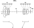
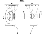
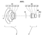
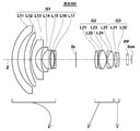
- Sectional drawing which shows the lens structure of the variable magnification optical system of Example 1 of this invention Sectional drawing which shows the lens structure of the variable magnification optical system of Example 2 of this invention
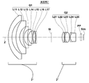
- Sectional drawing which shows the lens structure of the variable magnification optical system of Example 5 of this invention Sectional drawing which shows the lens structure of the variable magnification optical system of Example 6 of this invention.
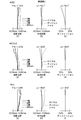
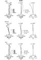
- FIGS. 9A to 9I are diagrams showing aberrations of the variable magnification optical system according to Example 1 of the present invention.
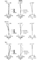
- FIGS. 10A to 10I are diagrams showing aberrations of the variable magnification optical system according to Example 2 of the present invention.
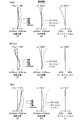
- 11A to 11I are diagrams showing aberrations of the variable magnification optical system according to Example 3 of the present invention.
- 12 (A) to 12 (I) are diagrams showing aberrations of the variable magnification optical system according to Example 4 of the present invention.
- FIGS. 13A to 13I are diagrams showing aberrations of the variable magnification optical system according to Example 5 of the present invention.
- FIGS. 14A to 14I show aberration diagrams of the variable magnification optical system according to Example 6 of the present invention.
- FIGS. 16A to 16I are diagrams showing aberrations of the variable magnification optical system according to Example 7 of the present invention.
- FIGS. 16A to 16I are diagrams showing aberrations of the variable magnification optical system according to Example 8 of the present invention.
- 1 is a schematic configuration diagram of an imaging apparatus according to an embodiment of the present invention.
- FIG. 1 is a cross-sectional view showing a configuration example of a variable magnification optical system according to an embodiment of the present invention, and corresponds to a variable magnification optical system of Example 1 described later.
- 2 to 8 are cross-sectional views showing other configuration examples according to the embodiment of the present invention, which respectively correspond to the variable magnification optical systems of Examples 2 to 8 described later. Since the basic configuration of the example shown in FIGS. 1 to 8 is the same and the method of illustration is also the same, here, the variable power optical system according to the embodiment of the present invention will be described mainly with reference to FIG. To do.
- This variable magnification optical system includes, in order from the object side, a first lens group G1 having negative refractive power, an aperture stop St, and a second lens group G2 having positive refractive power, and the first lens group G1.
- the magnification is changed by changing the distance between the first lens group G2 and the second lens group G2, and the correction of the image plane position accompanying the magnification is performed by moving the first lens group G1 in the optical axis direction. It is configured.
- the zoom optical system of the present invention performs zooming by moving the second lens group G2 in the optical axis direction, and moves the first lens group G1 in the optical axis direction to correct the image plane position accompanying the zooming. By doing so, a varifocal lens can be obtained.
- the zoom optical system of the present invention may be a zoom lens.
- the example shown in FIG. 1 is an example of a varifocal lens
- the second lens group G2 is configured to move toward the object side along the optical axis upon zooming from the wide-angle end to the telephoto end. .
- the aperture stop St is fixed with respect to the image plane Sim at the time of zooming.
- the aperture stop St shown in FIG. 1 does not necessarily indicate the size or shape, but indicates the position on the optical axis Z.
- the left side is the object side
- the right side is the image side.
- the lens configuration shown in FIG. 1 shows the lens arrangement when focusing on an object at infinity at the wide-angle end, and shows the movement locus of each lens group when zooming from the wide-angle end to the telephoto end. Are schematically indicated by arrows.
- FIG. 1 shows an example in which the parallel plate-like optical member PP that assumes these is arranged between the lens group closest to the image side and the image plane Sim.
- the first lens group G1 includes, in order from the object side, a lens L11 that is a negative meniscus lens having a convex surface facing the object side, and a lens L12 that is a negative meniscus lens having a convex surface facing the object side. And a lens L13 that is a negative lens, a lens L14 that is a positive lens, and a lens L15 that is a negative lens.
- a negative single lens (lens L15 in the example shown in FIG. 1) having a concave surface on the object side is disposed closest to the image side, and the second positive single lens from the image side (FIG. 1).
- the lens L14 is arranged.
- the positive single lens which is the second lens from the image side in the first lens group G1 has a convex surface facing the image side.
- axial chromatic aberration at the telephoto end is mainly reduced by the combination of the negative single lens and the positive single lens that are respectively disposed at the first and second positions from the image side of the first lens group G1. It becomes possible to correct well.
- the first lens group G1 includes at least one lens having a negative refractive power and having at least one aspheric surface.
- the first lens group G1 When the first lens group G1 places importance on miniaturization and cost reduction, it is preferable that the first lens group G1 has a five-lens configuration as in the examples shown in FIGS. However, in the case where higher optical performance and higher specifications are important, the first lens group G1 may have a six-lens configuration or a seven-lens configuration as in the examples shown in FIGS.
- the second lens group G2 includes, in order from the object side, a lens L21 that is a positive lens having at least one aspheric surface arranged closest to the object side, a lens L22 that is a negative lens, and a positive lens.
- a first cemented lens in which the lens L23 that is a lens is cemented in this order from the object side, and a second cemented lens in which the lens L24 that is a negative lens and the lens L25 that is a positive lens are cemented in this order from the object side. Configured.
- the positive lens L21 having at least one aspherical surface By disposing the positive lens L21 having at least one aspherical surface on the most object side of the second lens group G2, it becomes possible to obtain high optical performance while realizing a large aperture ratio and a high zoom ratio. . At the same time, it is possible to realize high optical performance from the visible region to the near infrared region by arranging two cemented lenses, the first and second cemented lenses having the above-described configuration, on the image side of the lens L21. .
- an optical system for use in a surveillance camera is desired to have a large aperture ratio, so that the degree of difficulty in correcting spherical aberration is higher than that of an optical system having a large F number.
- the present variable magnification optical system further aims to obtain good optical performance from the visible range to the near infrared range, and therefore the configuration of the cemented lens included in the second lens group G2 is important.
- the second lens group G2 preferably has a five-lens configuration including the lens L21 to the lens L25 having the above-mentioned configuration when importance is placed on size reduction and cost reduction.
- Both the image side surface of the negative lens L22 of the first cemented lens and the image side surface of the negative lens L24 of the second cemented lens of the second lens group G2 have a concave shape. These two surfaces are both cemented surfaces in which a negative lens and a positive lens are cemented. With this shape, chromatic aberration can be favorably corrected from the visible region to the near infrared region.
- first cemented lens and the second cemented lens of the second lens group G2 are preferably arranged adjacent to each other without interposing a lens member therebetween. Such an arrangement is advantageous for satisfactorily correcting chromatic aberration from the visible region to the near infrared region while reducing the size.
- the zoom optical system satisfies the following conditional expression (1). ⁇ 0.5 ⁇ (R23f + R23r) / (R23f ⁇ R23r) ⁇ 0.5 (1)
- R23f radius of curvature of object side surface of positive lens L23 constituting the first cemented lens
- R23r radius of curvature of image side surface of positive lens L23 constituting the first cemented lens
- Conditional expression (1) is an expression related to the shape of the positive lens L23 constituting the first cemented lens.
- the upper limit of conditional expression (1) is exceeded, the chromatic aberration correction effect of the first cemented lens is reduced, and it becomes difficult to achieve high optical performance from the visible range to the near infrared range.
- Below the lower limit of conditional expression (1) it becomes difficult to satisfactorily correct spherical aberration, particularly at the wide-angle end.
- conditional expression (1-1) ⁇ 0.25 ⁇ (R23f + R23r) / (R23f ⁇ R23r) ⁇ 0.25 (1-1)
- the zoom optical system satisfies the following conditional expressions (2) and (3). ⁇ d23> 70.0 (2) ⁇ d25> 70.0 (3)
- ⁇ d23 Abbe number at the d-line of the positive lens L23 constituting the first cemented lens
- ⁇ d25 Abbe number at the d-line of the positive lens L25 constituting the second cemented lens
- Conditional expressions (2) and (3) are expressions relating to the materials of the positive lens L23 constituting the first cemented lens and the positive lens L25 constituting the second cemented lens. Below the lower limit of conditional expressions (2) and (3), axial chromatic aberration increases from the wide-angle end to the entire telephoto end, and it becomes difficult to ensure good optical performance from the visible range to the near-infrared range.
- conditional expression (2-1) instead of the conditional expression (2)
- conditional expression (3-1) instead of the conditional expression (3)
- this zoom optical system satisfies the following conditional expression (4). -1 ⁇ R23r / R22f ⁇ 0 (4)
- R23r radius of curvature of image side surface of positive lens L23 constituting the first cemented lens
- R22f radius of curvature of object side surface of negative lens L22 constituting the first cemented lens
- Conditional expression (4) is an expression relating to the ratio of the radius of curvature of the object-side surface and the image-side surface of the first cemented lens as one lens. Since the variable magnification optical system has a configuration in which a first lens group G1 having a negative refractive power and a second lens group G2 having a positive refractive power are arranged in this order from the object side, normally, The first cemented lens included in the lens group G2 has a positive refractive power as a whole. If the upper limit of conditional expression (4) is exceeded, the first cemented lens has a meniscus shape, so the positive refractive power of the second lens group G2 becomes weak, and it becomes difficult to reduce the size and increase the magnification.
- the first cemented lens has a positive refractive power as a whole
- the first cemented lens has a biconvex shape within a range that satisfies the upper limit of the conditional expression (4). Therefore, the object side surface of the lens L22 is a convex surface.
- the lens L22 is a meniscus lens having a concave surface facing the image side within a range that satisfies the upper limit of the conditional expression (4).
- R22f becomes smaller and approaches the radius of curvature of the image side surface of the lens L22, so the negative refractive power of the lens L22 becomes weaker, and the chromatic aberration correction effect of the first cemented lens. It becomes difficult to realize high optical performance from the visible region to the near infrared region.
- conditional expression (4-1) is satisfied instead of conditional expression (4). ⁇ 0.7 ⁇ R23r / R22f ⁇ 0 (4-1)
- the zoom optical system satisfies the following conditional expression (5).
- R22r radius of curvature of the image side surface of the negative lens L22 constituting the first cemented lens
- R24r radius of curvature of the image side surface of the negative lens L24 constituting the second cemented lens
- Conditional expression (5) is an expression relating to the radius of curvature of the cemented surfaces of the two cemented lenses included in the second lens group G2. If the lower limit of conditional expression (5) is not reached, the chromatic aberration correction effect on the cemented surfaces of the lenses L22 and L24, which have a high axial chromatic aberration correction effect, will be reduced, and high optical performance will be realized from the visible range to the near infrared range. Becomes difficult.
- the zoom optical system satisfies the following conditional expression (6). 3.0 ⁇ fG2 / fw ⁇ 5.0 (6)
- fG2 focal length of the second lens group
- G2 focal length of the entire system at the wide angle end
- Conditional expression (6) is an expression relating to the ratio of the refractive power of the second lens group G2 to the entire system. If the upper limit of conditional expression (6) is exceeded, the amount of movement of the second lens group G2 accompanying zooming will increase, impeding downsizing of the optical system. If the lower limit of conditional expression (6) is not reached, the refractive power of the second lens group G2 becomes strong, and spherical aberration tends to be overcorrected, leading to performance degradation.
- variable magnification optical system further includes a third lens group having a positive refractive power fixed at the time of variable magnification on the image side of the second lens group G2, for example, as in the example shown in FIG. You may comprise.
- variable magnification optical system According to the variable magnification optical system according to the embodiment of the present invention described above, a high variable magnification ratio of about 2.6 to 4 times, while having a compact configuration with a minimum of two groups and a number of lenses of about 10. It becomes easy to realize a lens system having a large aperture ratio with an F number of about 1.3 to 1.6 at the wide angle end and a wide angle with a full angle of view of about 110 to 140 degrees at the wide angle end.
- the lens placed closest to the object is resistant to surface deterioration due to wind and rain, temperature changes due to direct sunlight, It is preferable to use a material resistant to chemicals such as detergents, that is, a material having high water resistance, weather resistance, acid resistance, chemical resistance, etc., and it is preferable to use a material that is hard and hard to break.
- the material of the lens arranged closest to the object side is preferably glass, or transparent ceramics may be used.
- variable magnification optical system when used in a harsh environment, a protective multilayer coating is preferably applied.
- an antireflection coating film for reducing ghost light during use may be applied.
- variable magnification optical system of the present invention The lens cross-sectional views of the variable magnification optical systems of Examples 1 to 8 are shown in FIGS. 1 to 8, respectively.
- the second lens group G2 moves toward the object side along the optical axis, thereby performing zooming from the wide-angle end to the telephoto end, and the image plane position associated with the zooming This correction is performed by moving the first lens group G1 in the optical axis direction.
- the first to fifth embodiments have a two-group configuration, and in order from the object side, the first lens group G1 has a five-lens configuration including lenses L11 to L15, and the second lens group has a five-lens configuration including lenses L21 to L25. .
- the sixth embodiment has a two-group configuration, and in order from the object side, the first lens group G1 has a six-lens configuration including lenses L11 to L16, and the second lens group G2 has a five-lens configuration including lenses L21 to L25.
- the seventh embodiment has a two-group configuration.
- the first lens group G1 has a seven-lens configuration including lenses L11 to L17
- the second lens group G2 has a five-lens configuration including lenses L21 to L25.
- the eighth embodiment has a three-group configuration.
- the first lens group G1 has a seven-lens configuration including lenses L11 to L17
- the second lens group G2 has a five-lens configuration including lenses L21 to L25.
- the lens group G3 has a two-lens configuration including lenses L31 to L32.
- the third lens group G3 of Example 8 is fixed at the time of zooming and has a positive refractive power. In all of Examples 1 to 8, an aperture stop St that is fixed at the time of zooming is disposed between the first lens group G1 and the second lens group G2.
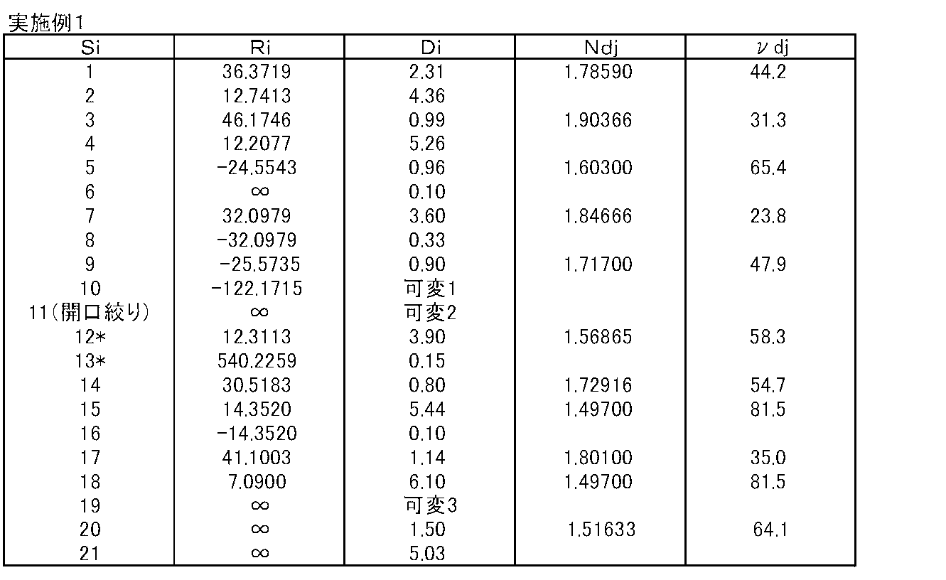
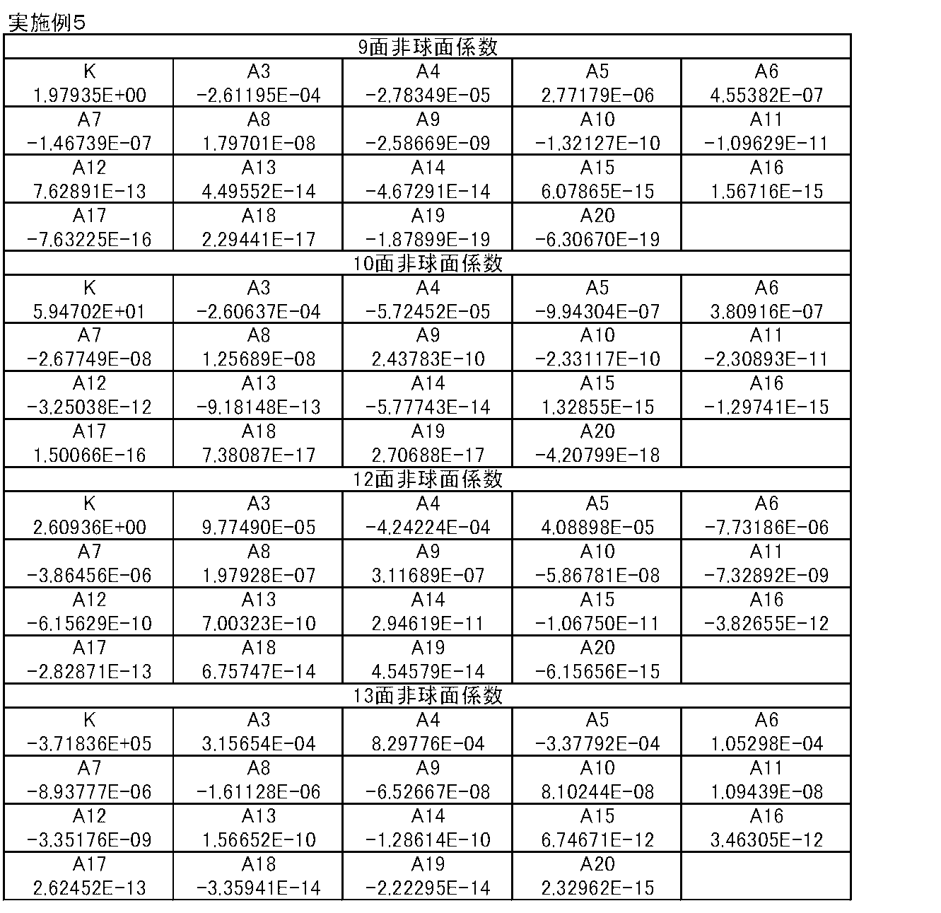
- Table 1 shows basic lens data of the variable magnification optical system of Example 1
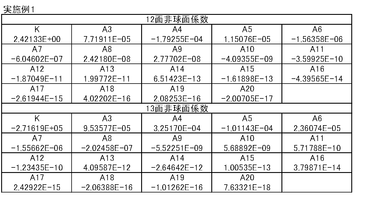
- Table 2 shows aspheric coefficients
- Table 3 shows data related to variable magnification.
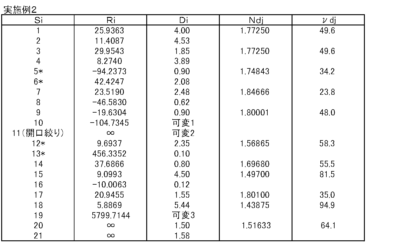
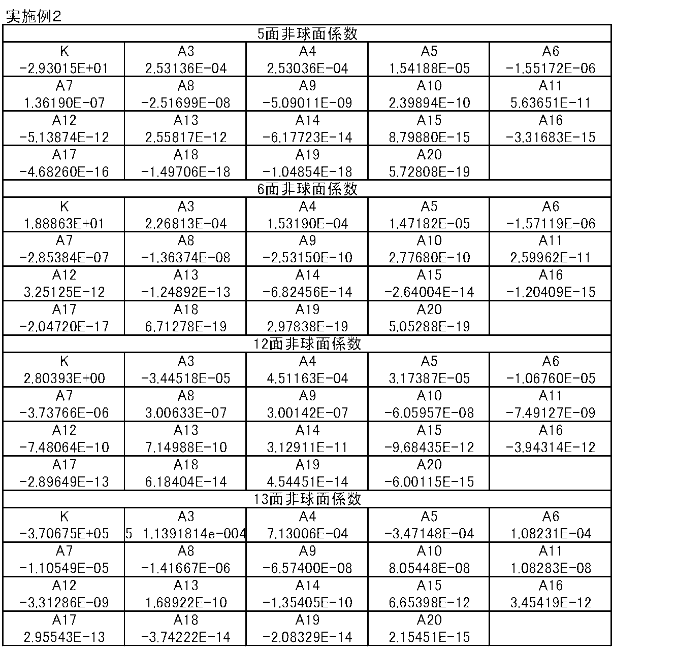
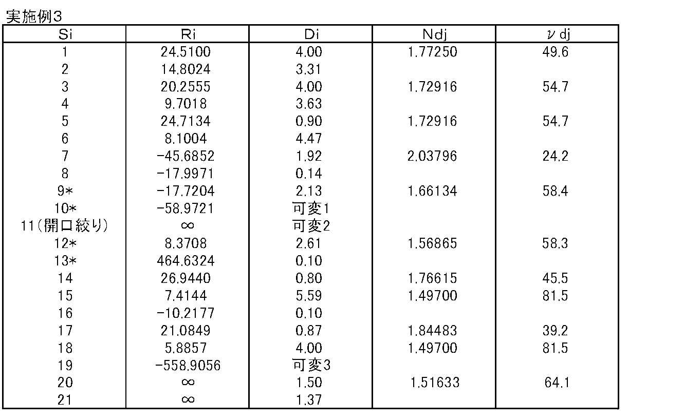
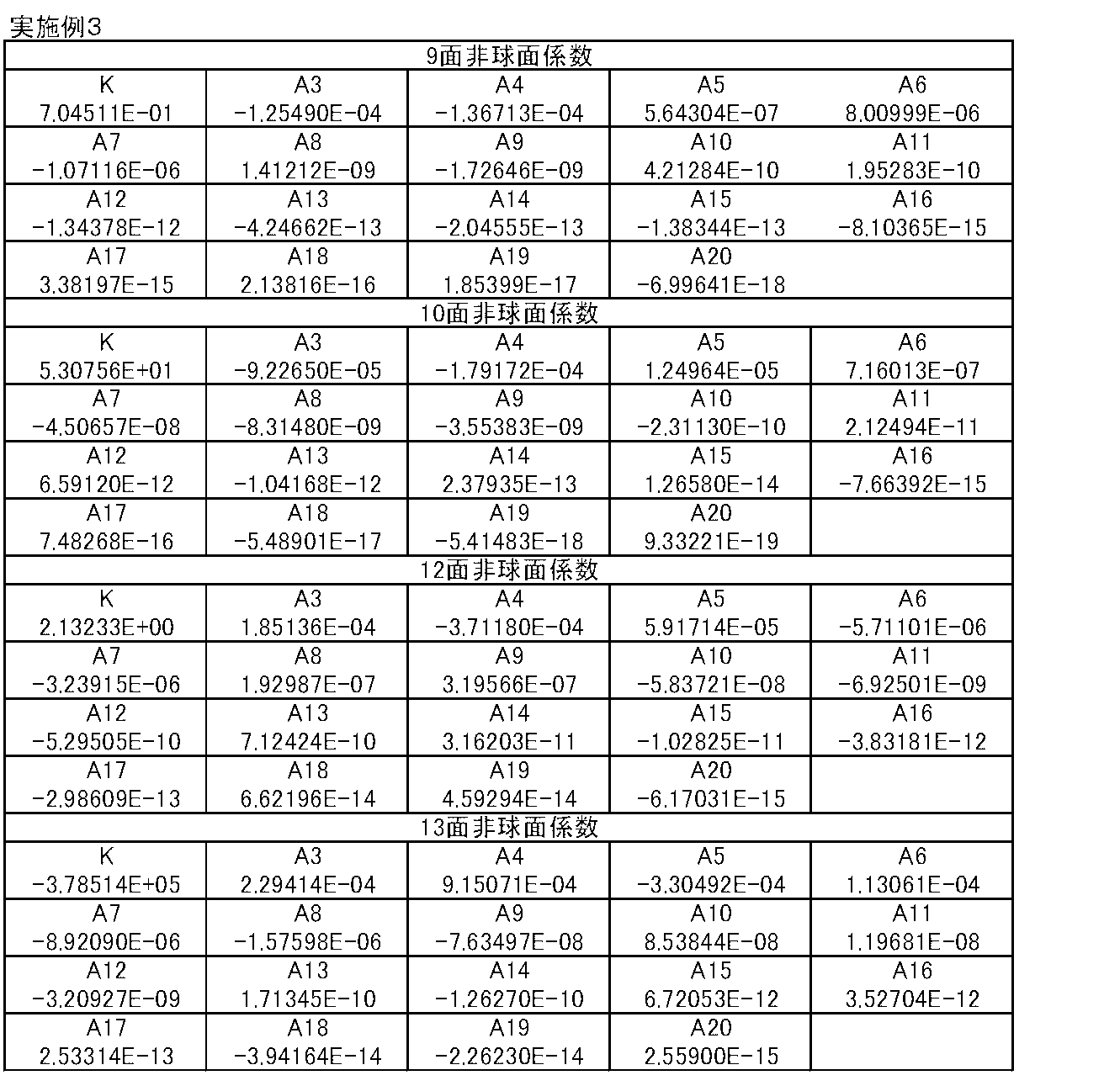
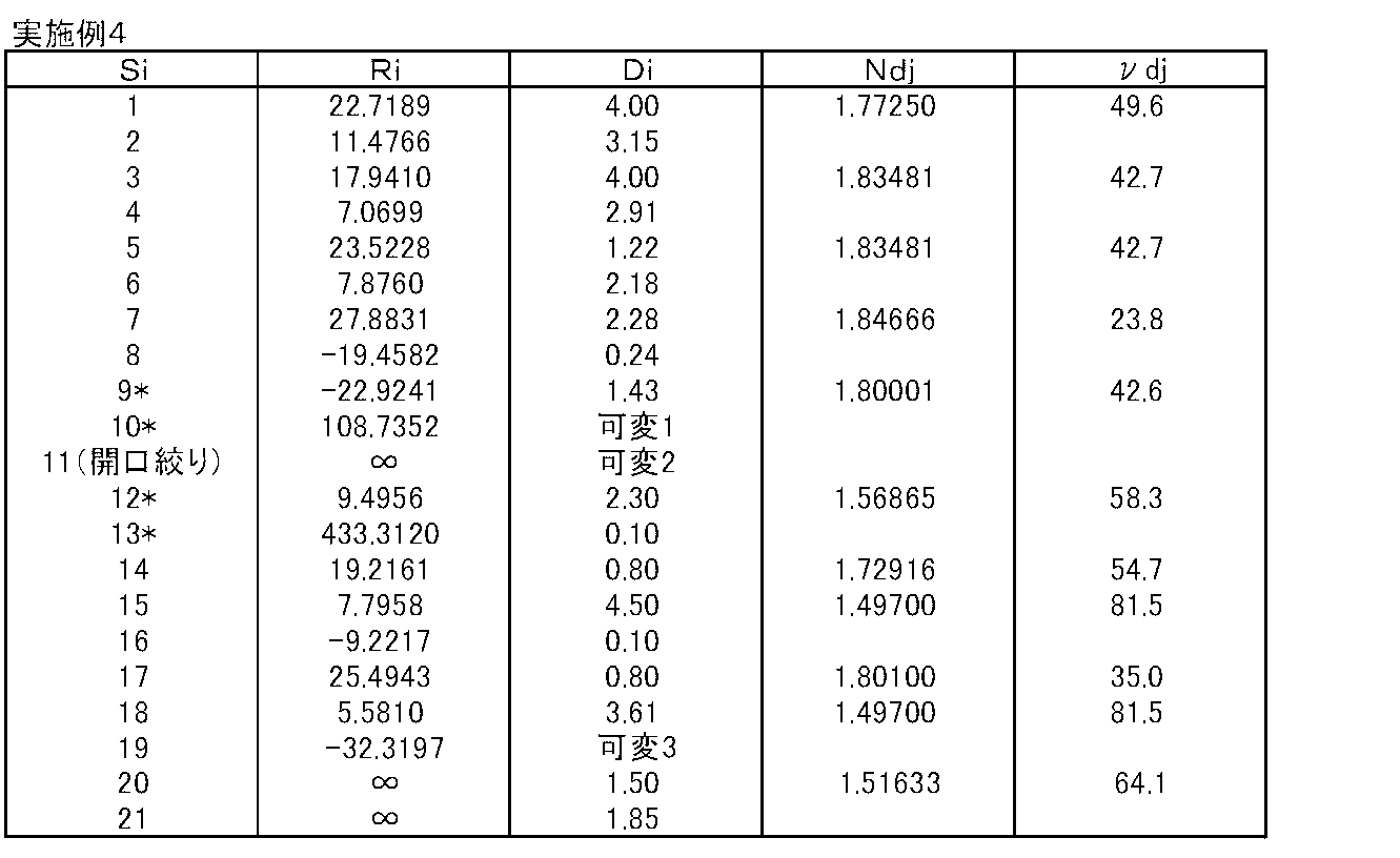
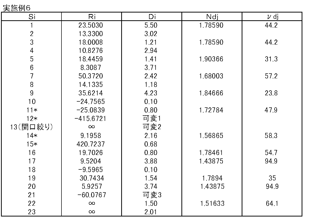
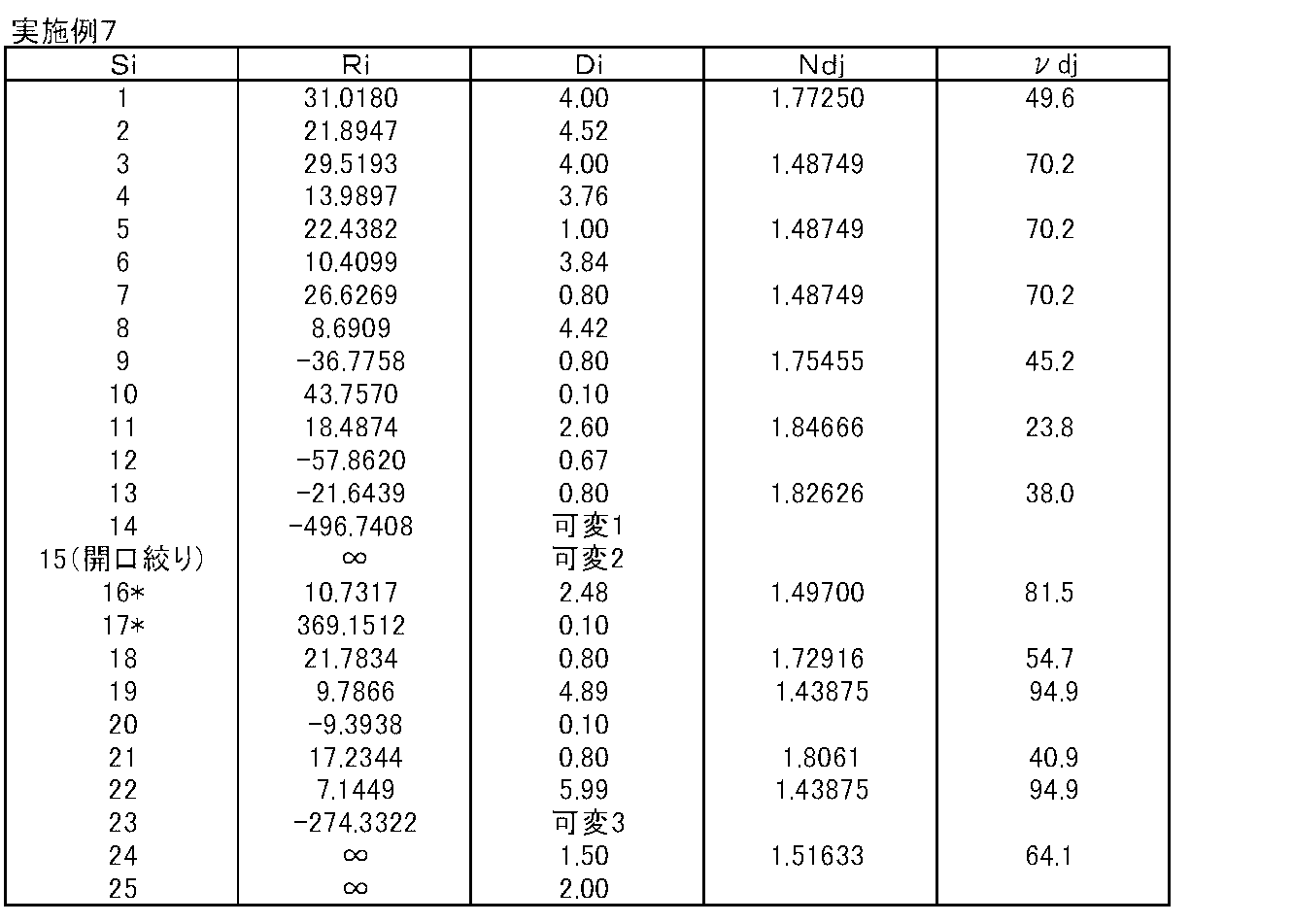
- Tables 3 to 24 show basic lens data and aspheric coefficients of the variable magnification optical systems of Examples 2 to 8, respectively.
- the meaning of the symbols in the table will be described by taking the example of Example 1 as an example. However, since the same applies to Examples 2 to 8, the tables of Examples 2 to 8 are duplicated. Description is omitted.
- the Di column indicates the surface spacing on the optical axis Z between the i-th surface and the i + 1-th surface.
- the numerical value in the bottom column of Di indicates the surface interval between the final surface in the table and the image surface Sim.
- the refractive index with respect to is shown
- the ⁇ dj column shows the Abbe number of the j-th optical element with respect to the d-line.
- the sign of the radius of curvature is positive when the surface shape is convex on the object side and negative when the surface shape is convex on the image side.
- the basic lens data table includes the aperture stop St and the optical member PP. In the surface number column of the surface corresponding to the aperture stop St, the word (aperture stop) is also described.
- variable 1 is the distance between the first lens group G1 and the aperture stop St
- variable 2 is the distance between the aperture stop St and the second lens group G2.
- the variable 3 is the distance between the second lens group G2 and the optical member PP in Examples 1 to 7, and the distance between the second lens group G2 and the third lens group G3 in Example 8.
- an aspherical surface has a surface number with an asterisk (*), and the paraxial radius of curvature is shown as the radius of curvature of the aspherical surface.
- Table 2 shows the aspheric coefficient of each aspheric surface.
- the numerical value “E ⁇ n” (n: integer) of the aspheric coefficient in Table 2 means “ ⁇ 10 ⁇ n”, and “E + n” means “ ⁇ 10n”.
- Zd Depth of aspheric surface (length of perpendicular drawn from a point on the aspherical surface at height Y to a plane perpendicular to the optical axis where the aspherical vertex contacts)
- Y Height (distance from the optical axis to the lens surface)
- C paraxial curvature K
- FIGS. 9A to 9C The spherical aberration, astigmatism, and distortion (distortion aberration) at the wide angle end of the variable magnification optical system of Example 1 are shown in FIGS. 9A to 9C, respectively, and spherical aberration and astigmatism at the intermediate focal position are shown.
- 9 (D) to FIG. 9 (F) show the distortion (distortion aberration)
- FIG. 9 (G) to FIG. 2 (I) show the spherical aberration, astigmatism, and distortion (distortion aberration) at the telephoto end, respectively.
- Each aberration diagram is based on the d-line, but the spherical aberration diagram also shows aberrations relating to the g-line (wavelength 435.8 nm), the C-line (wavelength 656.3 nm), and the wavelength 880 nm.
- the sagittal direction is indicated by a solid line, and the tangential direction is indicated by a dotted line.
- Fno Of spherical aberration diagram. Means F number, and ⁇ in other aberration diagrams means half angle of view.
- FIG. 16A to FIG. 16I show.
- Table 25 shows the corresponding values of conditional expressions (1) to (6) of the variable magnification optical systems of Examples 1 to 8. All the variable magnification optical systems of Examples 1 to 8 satisfy the conditional expressions (1) to (6).
- FIG. 17 shows a schematic configuration diagram of an imaging apparatus using the variable magnification optical system of the embodiment of the present invention as an example of the imaging apparatus of the embodiment of the present invention.
- the imaging device include a surveillance camera, a video camera, and an electronic still camera.
- An imaging apparatus 10 illustrated in FIG. 17 includes a variable magnification optical system 1, a filter 2 disposed on the image side of the variable magnification optical system 1, and an imaging element 3 that captures an image of a subject formed by the variable magnification optical system. And a signal processing unit 4 that performs arithmetic processing on an output signal from the image sensor 3.
- the variable magnification optical system 1 includes a negative first lens group G1, an aperture stop St, and a positive second lens group G2.
- FIG. 17 conceptually shows each lens group.
- the imaging device 3 converts an optical image formed by the variable magnification optical system 1 into an electric signal, and the imaging surface thereof is arranged so as to coincide with the image plane of the variable magnification optical system.
- a CCD or a CMOS can be used as the imaging element 3.
- the imaging apparatus 10 includes a zooming control unit 5 for zooming the zooming optical system 1, a focus control unit 6 for adjusting the focus of the zooming optical system 1, and the aperture diameter of the aperture stop St.
- a diaphragm control unit 7 is provided for changing. A configuration in which the aperture control unit 7 is omitted is also possible.
- the present invention has been described with reference to the embodiments and examples. However, the present invention is not limited to the above-described embodiments and examples, and various modifications can be made.
- the values of the radius of curvature, the surface interval, the refractive index, the Abbe number, the aspherical coefficient, etc. of each lens are not limited to the values shown in the above numerical examples, and can take other values.
Landscapes
- Physics & Mathematics (AREA)
- General Physics & Mathematics (AREA)
- Optics & Photonics (AREA)
- Nonlinear Science (AREA)
- Health & Medical Sciences (AREA)
- Toxicology (AREA)
- Lenses (AREA)
Abstract
変倍光学系において、小型でありながら、大口径比かつ高変倍比を有し、可視域から近赤外域にかけて高い光学性能を実現する。 変倍光学系は、物体側から順に、負の第1レンズ群(G1)、正の第2レンズ群(G2)を備え、変倍時にこれらの光軸方向の間隔が変化する。第1レンズ群(G1)の像側から1番目、2番目のレンズはそれぞれ、物体側に凹面を向けた負の単レンズ、正の単レンズである。第2レンズ群(G2)は、物体側から順に、最も物体側に配置された少なくとも1面の非球面を有する正レンズ、負レンズと正レンズからなる第1の接合レンズ、負レンズと正レンズからなる第2の接合レンズを含む。第1の接合レンズを構成する負レンズ、第2の接合レンズを構成する負レンズはともに像側の面が凹面である。 また、第1の接合レンズを構成する正レンズの面形状に関する条件式を満 たす。
Description
本発明は、ビデオカメラや電子スチルカメラ等に用いられる変倍光学系および撮像装置に関し、特に監視カメラ用途として好適で、可視域から近赤外域にわたる広い波長域で使用可能な変倍光学系および該変倍光学系を備えた撮像装置に関するものである。
従来、防犯や記録等の目的で監視カメラが用いられている。このような監視カメラ用の光学系としては、小型で安価に構成可能で、低照度の撮影条件下でも被写体を特定できるように大口径比であり、広い範囲を撮影可能な広角端から、より狭い範囲を拡大できる望遠端まで対応可能な高変倍比を有し、かつ、高い光学性能を有することが要求される。
また、昼夜兼用の監視カメラ用途では、無人の施設に設置し、昼間は可視光、夜間は近赤外光による撮影が行われることが多いため、可視域から近赤外域にわたる広い波長域で色収差が良好に補正され、高い光学性能を維持することが望まれている。
可視域から近赤外域にわたって色収差が良好に補正された変倍光学系としては、例えば、特許文献1に記載されたものが知られている。特許文献1に記載の光学系は、物体側から順に、負の第1レンズ群と正の第2レンズ群とを備え、第2レンズ群を光軸上で移動させることにより変倍を行い、この変倍に伴う像面位置の補正を第1レンズ群の移動により行うように構成されている。また、2つのレンズ群の間隔を変化させて変倍を行う2群構成の変倍光学系としては、例えば、下記特許文献2、3に記載のものがある。
しかしながら、特許文献2に記載の光学系は、一眼レフカメラ用のズームレンズであり、監視カメラに用いるにはFナンバーが大きすぎ、大口径比と言えない。特許文献3に記載の光学系は、投影レンズであり、監視カメラに用いるにはFナンバーが大きすぎる上に、変倍比が不足している。また、特許文献2、3に記載の光学系はともに、必ずしも可視域から近赤外域にわたる広い波長域での使用を想定したものではない。特許文献1に記載の光学系は、監視カメラ用として好適であるが、近年では、監視カメラ用途でも300万画素以上の撮像素子を有するカメラが現れ、これまで以上に高画質な映像を望む声が高まってきている。
本発明は、上記事情に鑑みてなされたもので、小型でありながら、大口径比かつ高変倍比を有し、可視域から近赤外域までの広い波長帯域にわたって高画質の画像を取得可能な高い光学性能を保持する変倍光学系および該変倍光学系を備えた撮像装置を提供することを目的とするものである。
本発明の第1の変倍光学系は、物体側から順に、負の屈折力を有する第1レンズ群と、絞りと、正の屈折力を有する第2レンズ群とを備え、第1レンズ群と第2レンズ群の光軸方向の間隔を変化させることにより変倍を行い、該変倍に伴う像面位置の補正を第1レンズ群を光軸方向に移動させることにより行うように構成された変倍光学系であって、第1レンズ群における、最も像側のレンズが物体側に凹面を向けた負の屈折力を有する単レンズであり、像側から2番目のレンズが正の屈折力を有する単レンズであり、第2レンズ群は、物体側から順に、最も物体側に配置された少なくとも1面の非球面を有する正レンズと、負レンズおよび正レンズを物体側からこの順に接合した第1の接合レンズと、負レンズおよび正レンズを物体側からこの順に接合した第2の接合レンズとを含み、第1の接合レンズを構成する負レンズおよび第2の接合レンズを構成する負レンズはともに像側の面が凹面であり、下記条件式(1)を満足することを特徴とするものである。
-0.5<(R23f+R23r)/(R23f-R23r)<0.5 … (1)
ただし、
R23f:第1の接合レンズを構成する正レンズの物体側の面の曲率半径
R23r:第1の接合レンズを構成する正レンズの像側の面の曲率半径
-0.5<(R23f+R23r)/(R23f-R23r)<0.5 … (1)
ただし、
R23f:第1の接合レンズを構成する正レンズの物体側の面の曲率半径
R23r:第1の接合レンズを構成する正レンズの像側の面の曲率半径
本発明の第2の変倍光学系は、物体側から順に、負の屈折力を有する第1レンズ群と、絞りと、正の屈折力を有する第2レンズ群とを備え、第1レンズ群と第2レンズ群の光軸方向の間隔を変化させることにより変倍を行い、該変倍に伴う像面位置の補正を第1レンズ群を光軸方向に移動させることにより行うように構成された変倍光学系であって、第1レンズ群における、最も像側のレンズが物体側に凹面を向けた負の屈折力を有する単レンズであり、像側から2番目のレンズが正の屈折力を有する単レンズであり、第2レンズ群は、物体側から順に、最も物体側に配置された少なくとも1面の非球面を有する正レンズと、負レンズおよび正レンズを物体側からこの順に接合した第1の接合レンズと、負レンズおよび正レンズを物体側からこの順に接合した第2の接合レンズとを含み、前記第1の接合レンズと前記第2の接合レンズとが隣接配置されており、前記第1の接合レンズを構成する前記負レンズおよび前記第2の接合レンズを構成する前記負レンズはともに像側の面が凹面であることを特徴とするものである。
本発明の第1、第2の変倍光学系においては、下記条件式(2)、(3)を満足することが好ましい。
νd23>70.0 … (2)
νd25>70.0 … (3)
ただし、
νd23:第1の接合レンズを構成する正レンズのd線におけるアッベ数
νd25:第2の接合レンズを構成する正レンズのd線におけるアッベ数
νd23>70.0 … (2)
νd25>70.0 … (3)
ただし、
νd23:第1の接合レンズを構成する正レンズのd線におけるアッベ数
νd25:第2の接合レンズを構成する正レンズのd線におけるアッベ数
また、本発明の第1、第2の変倍光学系においては、下記条件式(4)を満足することが好ましい。
-1<R23r/R22f<0 … (4)
ただし、
R23r:第1の接合レンズを構成する正レンズの像側の面の曲率半径
R22f:第1の接合レンズを構成する負レンズの物体側の面の曲率半径
-1<R23r/R22f<0 … (4)
ただし、
R23r:第1の接合レンズを構成する正レンズの像側の面の曲率半径
R22f:第1の接合レンズを構成する負レンズの物体側の面の曲率半径
また、本発明の第1、第2の変倍光学系においては、下記条件式(5)を満足することが好ましい。
|R22r|-|R24r|>0 … (5)
ただし、
R22r:第1の接合レンズを構成する負レンズの像側の面の曲率半径
R24r:第2の接合レンズを構成する負レンズの像側の面の曲率半径
|R22r|-|R24r|>0 … (5)
ただし、
R22r:第1の接合レンズを構成する負レンズの像側の面の曲率半径
R24r:第2の接合レンズを構成する負レンズの像側の面の曲率半径
また、本発明の第1、第2の変倍光学系においては、第1レンズ群における像側から2番目に配置されている正の屈折力を有する単レンズが、像側に凸面を向けた形状であることが好ましい。
また、本発明の第1、第2の変倍光学系においては、下記条件式(6)を満足することが好ましい。
3.0<fG2/fw<5.0 … (6)
ただし、
fG2:第2レンズ群の焦点距離
fw:広角端における全系の焦点距離
3.0<fG2/fw<5.0 … (6)
ただし、
fG2:第2レンズ群の焦点距離
fw:広角端における全系の焦点距離
なお、本発明の第1、第2の変倍光学系においては、レンズ群として、第1レンズ群および第2レンズ群のみを備える2群構成としてもよい。
あるいは、本発明の第1、第2の変倍光学系においては、第2レンズ群の像側に、変倍時に固定されている正の屈折力を有する第3レンズ群をさらに備えているように構成してもよい。その際、本発明の第1、第2の変倍光学系においては、レンズ群として、第1レンズ群、第2レンズ群、および第3レンズ群のみを備える3群構成としてもよい。
また、本発明の第1、第2の変倍光学系においては、第1レンズ群は、少なくとも1面が非球面の負の屈折力を有するレンズを少なくとも1つ含むように構成してもよい。
なお、上記本発明の変倍光学系におけるレンズの面形状、屈折力の符号は、非球面が含まれているものについては近軸領域で考えるものとする。
なお、「レンズ群」とは、必ずしも複数のレンズから構成されるものだけでなく、1枚のレンズのみで構成されるものも含むものとする。
なお、「単レンズ」とは、接合されていない1枚のレンズからなるものを意味する。
なお、曲率半径の符号は、物体側に凸面を向けた形状のものを正とし、像側に凸面を向けた形状のものを負とすることにする。
本発明の撮像装置は、上記記載の本発明の第1または第2の変倍光学系を備えたことを特徴とするものである。
本発明の第1の変倍光学系は、物体側から順に、負の第1レンズ群と、正の第2レンズ群とを備え、第1レンズ群と第2レンズ群の光軸方向の間隔を変化させることにより変倍を行い、該変倍に伴う像面位置の補正を第1レンズ群を光軸方向に移動させることにより行うように構成された変倍光学系において、第1レンズ群の像側から1番目、2番目に配置されるレンズの構成を好適に設定し、第2レンズ群のレンズ構成を詳細に好適に設定している。より詳しくは、第2レンズ群においては、最も物体側に配置された非球面レンズと2組の接合レンズを含み、2組の接合レンズの接合面の形状を好適に設定し、第1の接合レンズの要素である正レンズの形状を条件式(1)を満たすように設定している。したがって、本発明の第1の変倍光学系によれば、小型でありながら、大口径比かつ高変倍比を有し、可視域から近赤外域までの広い波長帯域にわたって高画質の画像を取得可能な高い光学性能を実現することができる。
本発明の第2の変倍光学系は、物体側から順に、負の第1レンズ群と、正の第2レンズ群とを備え、第1レンズ群と第2レンズ群の光軸方向の間隔を変化させることにより変倍を行い、該変倍に伴う像面位置の補正を第1レンズ群を光軸方向に移動させることにより行うように構成された変倍光学系において、第1レンズ群の像側から1番目、2番目に配置されるレンズの構成を好適に設定し、第2レンズ群のレンズ構成を詳細に好適に設定している。より詳しくは、第2レンズ群においては、最も物体側に配置された非球面レンズと2組の接合レンズを含み、2組の接合レンズの接合面の形状を好適に設定し、2組の接合レンズの配置関係を設定している。したがって、本発明の第2の変倍光学系によれば、小型でありながら、大口径比かつ高変倍比を有し、可視域から近赤外域までの広い波長帯域にわたって高画質の画像を取得可能な高い光学性能を実現することができる。
本発明の撮像装置は、本発明の第1または第2の変倍光学系を備えているため、小型に構成でき、低照度の条件下でも撮影可能で、高い倍率を有し、可視域から近赤外域までの広い波長帯域にわたって良好な映像を得ることができる。
以下、本発明の実施形態について図面を参照して詳細に説明する。図1は、本発明の実施形態にかかる変倍光学系の構成例を示す断面図であり、後述の実施例1の変倍光学系に対応している。また、図2~図8は、本発明の実施形態にかかる別の構成例を示す断面図であり、それぞれ後述の実施例2~8の変倍光学系に対応している。図1~図8に示す例の基本的な構成は同様であり、図示方法も同様であるため、ここでは主に図1を参照しながら、本発明の実施形態にかかる変倍光学系について説明する。
この変倍光学系は、物体側から順に、負の屈折力を有する第1レンズ群G1と、開口絞りStと、正の屈折力を有する第2レンズ群G2とを備え、第1レンズ群G1と第2レンズ群G2との光軸方向の間隔を変化させることにより変倍を行い、該変倍に伴う像面位置の補正を第1レンズ群G1を光軸方向に移動させることにより行うように構成されている。
本発明の変倍光学系は、第2レンズ群G2を光軸方向に移動させることにより変倍を行い、該変倍に伴う像面位置の補正を第1レンズ群G1を光軸方向に移動させることにより行うバリフォーカルレンズとすることができる。あるいは、本発明の変倍光学系は、ズームレンズとしてもよい。例えば、図1に示す例は、バリフォーカルレンズの例であり、広角端から望遠端への変倍に際して、第2レンズ群G2は光軸に沿って物体側に移動するように構成されている。
図1に示す例では、開口絞りStは変倍時に像面Simに対して固定されている。なお、図1に示す開口絞りStは必ずしも大きさや形状を表すものではなく、光軸Z上の位置を示すものである。図1では左側が物体側、右側が像側である。図1に示すレンズ構成は広角端において無限遠物体に合焦している時のレンズ配置を示したものであり、広角端から望遠端へ変倍するときの各レンズ群の移動軌跡をその下に模式的に矢印で示している。
変倍光学系が撮像装置に搭載される際には、撮像素子の撮像面を保護するカバーガラスや、撮像装置の仕様に応じた色分解プリズム等のプリズム、ローパスフィルタや赤外線カットフィルタ等の各種フィルタを備えるように撮像装置を構成することが好ましい。図1では、これらを想定した平行平板状の光学部材PPを最も像側のレンズ群と像面Simとの間に配置した例を示している。
第1レンズ群G1は、例えば図1に示すように、物体側から順に、物体側に凸面を向けた負メニスカスレンズであるレンズL11と、物体側に凸面を向けた負メニスカスレンズであるレンズL12と、負レンズであるレンズL13と、正レンズであるレンズL14と、負レンズであるレンズL15とが配列されてなる5枚構成とすることができる。
第1レンズ群G1は、最も像側に物体側の面が凹面である負の単レンズ(図1に示す例ではレンズL15)が配置され、像側から2番目に正の単レンズ(図1に示す例ではレンズL14)が配置されるように構成される。第1レンズ群G1の像側から1番目、2番目にこのようなレンズを配置することで、望遠端における球面収差と軸上色収差の良好な補正が可能になり、可視域から近赤外域にかけて良好な光学性能を確保することが可能になる。
第1レンズ群G1において像側から2番目のレンズとなる正の単レンズは、像側に凸面を向けた形状とすることが好ましい。このような構成とすることで、第1レンズ群G1の像側から1番目と2番目それぞれに配置される負の単レンズと正の単レンズの組み合わせによって、主に望遠端における軸上色収差を良好に補正することが可能になる。
また、第1レンズ群G1は、少なくとも1面が非球面の負の屈折力を有するレンズを少なくとも1つ含むことが好ましい。このように構成することで、広角端における非点収差を良好に保つことが可能となると同時に、望遠端における球面収差も良好に補正することが可能となる。
第1レンズ群G1は、小型化、低コスト化を重視する場合は、図1~図5に示す例のように、5枚構成とすることが好ましい。しかし、より高い光学性能や高諸元を重視する場合は、第1レンズ群G1は、図6~図8に示す例のように、6枚構成や7枚構成としてもよい。
第2レンズ群G2は、図1に示すように、物体側から順に、最も物体側に配置された少なくとも1面の非球面を有する正レンズであるレンズL21と、負レンズであるレンズL22および正レンズであるレンズL23を物体側からこの順に接合した第1の接合レンズと、負レンズであるレンズL24および正レンズであるレンズL25を物体側からこの順に接合した第2の接合レンズとを含むように構成される。
第2レンズ群G2の最も物体側に少なくとも1面の非球面を有する正のレンズL21を配置することで、大口径比と高変倍比を実現しながら高い光学性能を得ることが可能になる。そして同時に、レンズL21の像側に、上記構成の第1、第2の接合レンズという2つの接合レンズを配置することで、可視域から近赤外域にかけて高い光学性能を実現することが可能になる。
仮に、第1、第2の接合レンズを構成する正・負レンズの順番を上記構成と異ならせたものでは、色の球面収差を良好に補正することが困難になる。上述したように、監視カメラ用途の光学系は大口径比であることが望まれるため、Fナンバーの大きな光学系に比べて球面収差の補正の難度が高くなる。本変倍光学系はさらに、可視域から近赤外域まで良好な光学性能を得ることを目的としているため、第2レンズ群G2に含まれる接合レンズの構成は重要である。
第2レンズ群G2は、小型化や低コスト化を重視する場合は、上記構成のレンズL21~レンズL25からなる5枚構成とすることが好ましい。
第2レンズ群G2の第1の接合レンズの負のレンズL22の像側の面および第2の接合レンズの負のレンズL24の像側の面は、ともに凹面形状を有する。この2つの面はともに負レンズと正レンズが接合されている接合面であり、このような形状とすることで、可視域から近赤外域にかけて色収差を良好に補正することが可能になる。
なお、第2レンズ群G2の第1の接合レンズと第2の接合レンズとは、その間にレンズ部材を介在させることなく、隣り合うように配置されていることが好ましい。このように配置することで、小型化を図りつつ、可視域から近赤外域にかけて色収差を良好に補正することに有利となる。
また、本変倍光学系は、下記条件式(1)を満足することが好ましい。
-0.5<(R23f+R23r)/(R23f-R23r)<0.5 … (1)
ただし、
R23f:第1の接合レンズを構成する正のレンズL23の物体側の面の曲率半径
R23r:第1の接合レンズを構成する正のレンズL23の像側の面の曲率半径
-0.5<(R23f+R23r)/(R23f-R23r)<0.5 … (1)
ただし、
R23f:第1の接合レンズを構成する正のレンズL23の物体側の面の曲率半径
R23r:第1の接合レンズを構成する正のレンズL23の像側の面の曲率半径
条件式(1)は、第1の接合レンズを構成する正のレンズL23の形状に関する式である。条件式(1)の上限を上回ると、第1の接合レンズの色収差補正効果が低減し、可視域から近赤外域まで高い光学性能を実現することが困難になる。条件式(1)の下限を下回ると、特に広角端における球面収差を良好に補正することが困難になる。
上記事情から、条件式(1)に代えて下記条件式(1-1)を満足することがより好ましい。
-0.25<(R23f+R23r)/(R23f-R23r)<0.25 … (1-1)
-0.25<(R23f+R23r)/(R23f-R23r)<0.25 … (1-1)
また、本変倍光学系は、下記条件式(2)、(3)を満足することが好ましい。
νd23>70.0 … (2)
νd25>70.0 … (3)
ただし、
νd23:第1の接合レンズを構成する正のレンズL23のd線におけるアッベ数
νd25:第2の接合レンズを構成する正のレンズL25のd線におけるアッベ数
νd23>70.0 … (2)
νd25>70.0 … (3)
ただし、
νd23:第1の接合レンズを構成する正のレンズL23のd線におけるアッベ数
νd25:第2の接合レンズを構成する正のレンズL25のd線におけるアッベ数
条件式(2)、(3)は、第1の接合レンズを構成する正のレンズL23、第2の接合レンズを構成する正のレンズL25の材質に関する式である。条件式(2)、(3)の下限を下回ると、広角端から望遠端全域にかけて軸上色収差が増大し、可視域から近赤外域にかけて良好な光学性能を確保することが困難となる。
上記事情から、条件式(2)に代えて下記条件式(2-1)を満足することがより好ましく、条件式(3)に代えて下記条件式(3-1)を満足することがより好ましい。
νd23>80.0 … (2-1)
νd25>80.0 … (3-1)
νd23>80.0 … (2-1)
νd25>80.0 … (3-1)
また、本変倍光学系は、下記条件式(4)を満足することが好ましい。
-1<R23r/R22f<0 … (4)
ただし、
R23r:第1の接合レンズを構成する正のレンズL23の像側の面の曲率半径
R22f:第1の接合レンズを構成する負のレンズL22の物体側の面の曲率半径
-1<R23r/R22f<0 … (4)
ただし、
R23r:第1の接合レンズを構成する正のレンズL23の像側の面の曲率半径
R22f:第1の接合レンズを構成する負のレンズL22の物体側の面の曲率半径
条件式(4)は、第1の接合レンズを1つのレンズと見立てたとき、そのレンズの物体側の面と像側の面の曲率半径の比に関する式である。本変倍光学系が、物体側から順に、負の屈折力を有する第1レンズ群G1と、正の屈折力を有する第2レンズ群G2とを配列した構成であることから、通常、第2レンズ群G2に含まれる第1の接合レンズは全体として正の屈折力を持つことになる。条件式(4)の上限を上回ると、第1の接合レンズがメニスカス形状となるため、第2レンズ群G2の正の屈折力が弱くなり、小型化・高倍率化しにくくなる。
第1の接合レンズが全体として正の屈折力を持つ場合、条件式(4)の上限を満足する範囲では、第1の接合レンズは両凸形状となる。よって、レンズL22の物体側の面は凸面となる。上述したように、レンズL22の像側の面は凹面であるから、条件式(4)の上限を満足する範囲では、レンズL22は像側に凹面を向けたメニスカスレンズとなる。条件式(4)の下限を下回ると、R22fが小さくなり、レンズL22の像側の面の曲率半径に近づくため、レンズL22の負の屈折力が弱くなり、第1の接合レンズの色収差補正効果が低減し、可視域から近赤外域まで高い光学性能を実現することが困難になる。
上記事情から、条件式(4)に代えて下記条件式(4-1)を満足することがより好ましい。
-0.7<R23r/R22f<0 … (4-1)
-0.7<R23r/R22f<0 … (4-1)
また、本変倍光学系は、下記条件式(5)を満足することが好ましい。
|R22r|-|R24r|>0 … (5)
ただし、
R22r:第1の接合レンズを構成する負のレンズL22の像側の面の曲率半径
R24r:第2の接合レンズを構成する負のレンズL24の像側の面の曲率半径
|R22r|-|R24r|>0 … (5)
ただし、
R22r:第1の接合レンズを構成する負のレンズL22の像側の面の曲率半径
R24r:第2の接合レンズを構成する負のレンズL24の像側の面の曲率半径
条件式(5)は、第2レンズ群G2に含まれる2つの接合レンズの接合面の曲率半径に関する式である。条件式(5)の下限を下回ると、軸上色収差の補正効果が高いレンズL22、レンズL24の接合面での色収差補正効果が低減し、可視域から近赤外域まで高い光学性能を実現することが困難になる。
また、本変倍光学系は、下記条件式(6)を満足することが好ましい。
3.0<fG2/fw<5.0 … (6)
ただし、
fG2:第2レンズ群G2の焦点距離
fw:広角端における全系の焦点距離
3.0<fG2/fw<5.0 … (6)
ただし、
fG2:第2レンズ群G2の焦点距離
fw:広角端における全系の焦点距離
条件式(6)は、全系に対する第2レンズ群G2の屈折力の比に関する式である。条件式(6)の上限を上回ると、変倍に伴う第2レンズ群G2の移動量が増大し光学系の小型化を阻害する。条件式(6)の下限を下回ると、第2レンズ群G2の屈折力が強くなり、球面収差が補正過剰傾向となり性能の劣化を招く。
なお、本変倍光学系は、例えば図8に示す例のように、第2レンズ群G2の像側に、変倍時に固定されている正の屈折力を有する第3レンズ群をさらに備えるように構成してもよい。このように構成することで、変倍域の中間の位置で発生する球面収差の過剰補正傾向を改善し、広角端・望遠端のみならず中間域においても良好な光学性能を維持することが可能となる。
以上述べた本発明の実施形態にかかる変倍光学系によれば、最少2群構成でレンズ枚数が10枚程度というコンパクトな構成でありながら、2.6~4倍程度の高変倍比、広角端でのFナンバーが1.3~1.6程度の大口径比、広角端で全画角が110~140度程度の広角を同時に有するレンズ系を実現することが容易になる。
なお、本変倍光学系が例えば屋外等の厳しい環境において使用される場合には、最も物体側に配置されるレンズには、風雨による表面劣化、直射日光による温度変化に強く、さらには油脂・洗剤等の化学薬品に強い材料、すなわち耐水性、耐候性、耐酸性、耐薬品性等が高い材料を用いることが好ましく、堅く、割れにくい材質を用いることが好ましい。これらの要望を満たすことが重視される場合は最も物体側に配置されるレンズの材質はガラスとすることが好ましく、または透明なセラミックスを用いてもよい。
また、本変倍光学系が厳しい環境において使用される場合には、保護用の多層膜コートが施されることが好ましい。さらに、保護用コート以外にも、使用時のゴースト光低減等のための反射防止コート膜を施すようにしてもよい。
なお、図1に示す例では、最も像側のレンズのさらに像側に光学部材PPを配置した例を示したが、各種フィルタを各レンズの間に配置することも可能であり、あるいは、いずれかのレンズのレンズ面に、各種フィルタと同様の作用を有するコートを施してもよい。
次に、本発明の変倍光学系の数値実施例について説明する。実施例1~8の変倍光学系のレンズ断面図はそれぞれ図1~図8に示したものである。実施例1~8の変倍光学系は、第2レンズ群G2が光軸に沿って物体側に移動することにより広角端から望遠端への変倍を行い、該変倍に伴う像面位置の補正を第1レンズ群G1を光軸方向に移動させることにより行うように構成されている。
実施例1~5は、2群構成であり、物体側から順に、第1レンズ群G1がレンズL11~L15からなる5枚構成、第2レンズ群がレンズL21~L25からなる5枚構成である。実施例6は、2群構成であり、物体側から順に、第1レンズ群G1がレンズL11~L16からなる6枚構成、第2レンズ群G2がレンズL21~L25からなる5枚構成である。実施例7は、2群構成であり、物体側から順に、第1レンズ群G1がレンズL11~L17からなる7枚構成、第2レンズ群G2がレンズL21~L25からなる5枚構成である。実施例8は、3群構成であり、物体側から順に、第1レンズ群G1がレンズL11~L17からなる7枚構成、第2レンズ群G2がレンズL21~L25からなる5枚構成、第3レンズ群G3がレンズL31~L32からなる2枚構成である。実施例8の第3レンズ群G3は、変倍時に固定されており正の屈折力を有するものである。実施例1~8全て第1レンズ群G1と第2レンズ群G2の間に変倍時に固定されている開口絞りStが配置されている。
実施例1の変倍光学系の基本レンズデータを表1に、非球面係数を表2に、変倍に関するデータを表3に示す。同様に、実施例2~8の変倍光学系の基本レンズデータ、非球面係数をそれぞれ表3~表24に示す。以下では、表中の記号の意味について、実施例1のものを例にとり説明するが、実施例2~8のものについても基本的に同様であるため、実施例2~8の表については重複説明を省略する。
表1の基本レンズデータの表において、Siの欄には最も物体側の構成要素の物体側の面を1番目として像側に向かうに従い順次増加するi番目(i=1、2、3、…)の面番号を示し、Riの欄にはi番目の面の曲率半径を示し、Diの欄にはi番目の面とi+1番目の面との光軸Z上の面間隔を示している。ただし、Diの最下欄の数値は表中の最終面と像面Simとの面間隔を示している。また、Ndjの欄には最も物体側の光学要素を1番目として像側に向かうに従い順次増加するj番目(j=1、2、3、…)の光学要素のd線(波長587.6nm)に対する屈折率を示し、νdjの欄にはj番目の光学要素のd線に対するアッベ数を示している。
なお、曲率半径の符号は、面形状が物体側に凸の場合を正、像側に凸の場合を負としている。基本レンズデータの表には、開口絞りSt、光学部材PPも含めて示している。開口絞りStに相当する面の面番号の欄には(開口絞り)という語句も合わせて記載している。
基本レンズデータの表において、変倍時に間隔が変化する面間隔の欄には可変1、可変2、可変3と記載している。可変1は第1レンズ群G1と開口絞りStとの間隔であり、可変2は開口絞りStと第2レンズ群G2との間隔である。可変3は、実施例1~7については第2レンズ群G2と光学部材PPとの間隔であり、実施例8については第2レンズ群G2と第3レンズ群G3との間隔である。
基本レンズデータの表では、非球面は面番号に*印を付しており、非球面の曲率半径として近軸の曲率半径の数値を示している。表2に各非球面の非球面係数を示す。表2の非球面係数の数値の「E-n」(n:整数)は「×10-n」を意味し、「E+n」は「×10n」を意味する。非球面係数は、以下の式で表される非球面式における各係数K、Am(m=3、4、5、…20)の値である。

ただし、
Zd:非球面深さ(高さYの非球面上の点から、非球面頂点が接する光軸に垂直な平面に下ろした垂線の長さ)
Y:高さ(光軸からのレンズ面までの距離)
C:近軸曲率
K、Am:非球面係数(m=3、4、5、…20)
Zd:非球面深さ(高さYの非球面上の点から、非球面頂点が接する光軸に垂直な平面に下ろした垂線の長さ)
Y:高さ(光軸からのレンズ面までの距離)
C:近軸曲率
K、Am:非球面係数(m=3、4、5、…20)
表3の変倍に関するデータでは、広角端、中間焦点位置、望遠端の各位置における、全系の焦点距離、Fno.、全画角、可変1、可変2、可変3の値を示す。下記表では、角度の単位としては度を用い、長さの単位としてはmmを用いているが、光学系は比例拡大又は比例縮小して使用することが可能なため、他の適当な単位を用いることもできる。また、本明細書に記載する各表に示す数値は、所定の桁でまるめたものである。














実施例1の変倍光学系の広角端における球面収差、非点収差、ディストーション(歪曲収差)をそれぞれ図9(A)~図9(C)に示し、中間焦点位置における球面収差、非点収差、ディストーション(歪曲収差)をそれぞれ図9(D)~図9(F)に示し、望遠端における球面収差、非点収差、ディストーション(歪曲収差)をそれぞれ図9(G)~図2(I)に示す。各収差図はd線を基準としたものであるが、球面収差図ではg線(波長435.8nm)、C線(波長656.3nm)、波長880nmに関する収差も示す。非点収差図では、サジタル方向については実線で、タンジェンシャル方向については点線で示している。球面収差図のFno.はFナンバーを意味し、その他の収差図のωは半画角を意味する。
同様に、実施例2~8の変倍光学系の広角端、中間焦点位置、望遠端における各収差図を図10(A)~図10(I)、図11(A)~図11(I)、図12(A)~図12(I)、図13(A)~図13(I)、図14(A)~図14(I)、図15(A)~図15(I)、図16(A)~図16(I)に示す。
実施例1~8の変倍光学系の条件式(1)~(6)の対応値を表25に示す。実施例1~8の変倍光学系は全て、条件式(1)~(6)を満足している。

図17に、本発明の実施形態の撮像装置の一例として、本発明の実施形態の変倍光学系を用いた撮像装置の概略構成図を示す。撮像装置としては、例えば、監視カメラ、ビデオカメラ、電子スチルカメラ等を挙げることができる。
図17に示す撮像装置10は、変倍光学系1と、変倍光学系1の像側に配置されたフィルタ2と、変倍光学系によって結像される被写体の像を撮像する撮像素子3と、撮像素子3からの出力信号を演算処理する信号処理部4を備える。変倍光学系1は、負の第1レンズ群G1と、開口絞りStと、正の第2レンズ群G2を有するものであり、図17では各レンズ群を概念的に示している。撮像素子3は、変倍光学系1により形成される光学像を電気信号に変換するものであり、その撮像面は変倍光学系の像面に一致するように配置される。撮像素子3としては例えばCCDやCMOS等を用いることができる。
また、撮像装置10は、変倍光学系1の変倍を行うための変倍制御部5と、変倍光学系1のフォーカスを調整するためのフォーカス制御部6と、開口絞りStの絞り径を変更するための絞り制御部7を備える。なお、絞り制御部7を省略した構成も可能である。
以上、実施形態および実施例を挙げて本発明を説明したが、本発明は上記実施形態および実施例に限定されず、種々の変形が可能である。例えば、各レンズの曲率半径、面間隔、屈折率、アッベ数、非球面係数等の値は、上記各数値実施例で示した値に限定されず、他の値をとり得るものである。
Claims (16)
- 物体側から順に、負の屈折力を有する第1レンズ群と、絞りと、正の屈折力を有する第2レンズ群とを備え、前記第1レンズ群と前記第2レンズ群の光軸方向の間隔を変化させることにより変倍を行い、該変倍に伴う像面位置の補正を前記第1レンズ群を光軸方向に移動させることにより行うように構成された変倍光学系であって、
前記第1レンズ群における、最も像側のレンズが物体側に凹面を向けた負の屈折力を有する単レンズであり、像側から2番目のレンズが正の屈折力を有する単レンズであり、
前記第2レンズ群は、物体側から順に、最も物体側に配置された少なくとも1面の非球面を有する正レンズと、負レンズおよび正レンズを物体側からこの順に接合した第1の接合レンズと、負レンズおよび正レンズを物体側からこの順に接合した第2の接合レンズとを含み、
前記第1の接合レンズを構成する前記負レンズおよび前記第2の接合レンズを構成する前記負レンズはともに像側の面が凹面であり、
下記条件式(1)を満足することを特徴とする変倍光学系。
-0.5<(R23f+R23r)/(R23f-R23r)<0.5 … (1)
ただし、
R23f:前記第1の接合レンズを構成する前記正レンズの物体側の面の曲率半径
R23r:前記第1の接合レンズを構成する前記正レンズの像側の面の曲率半径 - 下記条件式(1-1)を満足することを特徴とする請求項1記載の変倍光学系。
-0.25<(R23f+R23r)/(R23f-R23r)<0.25 … (1-1) - 物体側から順に、負の屈折力を有する第1レンズ群と、絞りと、正の屈折力を有する第2レンズ群とを備え、前記第1レンズ群と前記第2レンズ群の光軸方向の間隔を変化させることにより変倍を行い、該変倍に伴う像面位置の補正を前記第1レンズ群を光軸方向に移動させることにより行うように構成された変倍光学系であって、
前記第1レンズ群における、最も像側のレンズが物体側に凹面を向けた負の屈折力を有する単レンズであり、像側から2番目のレンズが正の屈折力を有する単レンズであり、
前記第2レンズ群は、物体側から順に、最も物体側に配置された少なくとも1面の非球面を有する正レンズと、負レンズおよび正レンズを物体側からこの順に接合した第1の接合レンズと、負レンズおよび正レンズを物体側からこの順に接合した第2の接合レンズとを含み、
前記第1の接合レンズと前記第2の接合レンズとが隣接配置されており、
前記第1の接合レンズを構成する前記負レンズおよび前記第2の接合レンズを構成する前記負レンズはともに像側の面が凹面であることを特徴とする変倍光学系。 - 下記条件式(2)、(3)を満足することを特徴とする請求項1から3のいずれか1項に記載の変倍光学系。
νd23>70.0 … (2)
νd25>70.0 … (3)
ただし、
νd23:前記第1の接合レンズを構成する前記正レンズのd線におけるアッベ数
νd25:前記第2の接合レンズを構成する前記正レンズのd線におけるアッベ数 - 下記条件式(2-1)を満足することを特徴とする請求項4記載の変倍光学系。
νd23>80.0 … (2-1) - 下記条件式(3-1)を満足することを特徴とする請求項4または5記載の変倍光学系。
νd25>80.0 … (3-1) - 下記条件式(4)を満足することを特徴とする請求項1から6のいずれか1項に記載の変倍光学系。
-1<R23r/R22f<0 … (4)
ただし、
R23r:前記第1の接合レンズを構成する前記正レンズの像側の面の曲率半径
R22f:前記第1の接合レンズを構成する前記負レンズの物体側の面の曲率半径 - 下記条件式(4-1)を満足することを特徴とする請求項7記載の変倍光学系。
-0.7<R23r/R22f<0 … (4-1) - 下記条件式(5)を満足することを特徴とする請求項1から8のいずれか1項に記載の変倍光学系。
|R22r|-|R24r|>0 … (5)
ただし、
R22r:前記第1の接合レンズを構成する前記負レンズの像側の面の曲率半径
R24r:前記第2の接合レンズを構成する前記負レンズの像側の面の曲率半径 - 前記第1レンズ群における像側から2番目に配置されている正の屈折力を有する前記単レンズが、像側に凸面を向けた形状であることを特徴とする請求項1から9のいずれか1項に記載の変倍光学系。
- 下記条件式(6)を満足することを特徴とする請求項1から10のいずれか1項に記載の変倍光学系。
3.0<fG2/fw<5.0 … (6)
ただし、
fG2:前記第2レンズ群の焦点距離
fw:広角端における全系の焦点距離 - 前記変倍光学系が、レンズ群として、前記第1レンズ群および前記第2レンズ群のみを備えることを特徴とする請求項1から11のいずれか1項に記載の変倍光学系。
- 前記第2レンズ群の像側に、変倍時に固定されている正の屈折力を有する第3レンズ群をさらに備えていることを特徴とする請求項1から11のいずれか1項に記載の変倍光学系。
- 前記変倍光学系が、レンズ群として、前記第1レンズ群、前記第2レンズ群、および前記第3レンズ群のみを備えることを特徴とする請求項13に記載の変倍光学系。
- 前記第1レンズ群は、少なくとも1面が非球面の負の屈折力を有するレンズを少なくとも1つ含むことを特徴とする請求項1から14のいずれか1項に記載の変倍光学系。
- 請求項1から15のいずれか1項に記載の変倍光学系を備えたことを特徴とする撮像装置。
Priority Applications (3)
| Application Number | Priority Date | Filing Date | Title |
|---|---|---|---|
| JP2013513924A JP5806299B2 (ja) | 2011-05-09 | 2012-05-07 | 変倍光学系および撮像装置 |
| CN201280022232.6A CN103518153B (zh) | 2011-05-09 | 2012-05-07 | 可变放大倍率光学系统和成像设备 |
| US14/061,052 US8947786B2 (en) | 2011-05-09 | 2013-10-23 | Variable magnification optical system and imaging apparatus |
Applications Claiming Priority (2)
| Application Number | Priority Date | Filing Date | Title |
|---|---|---|---|
| JP2011104128 | 2011-05-09 | ||
| JP2011-104128 | 2011-05-09 |
Related Child Applications (1)
| Application Number | Title | Priority Date | Filing Date |
|---|---|---|---|
| US14/061,052 Continuation US8947786B2 (en) | 2011-05-09 | 2013-10-23 | Variable magnification optical system and imaging apparatus |
Publications (1)
| Publication Number | Publication Date |
|---|---|
| WO2012153505A1 true WO2012153505A1 (ja) | 2012-11-15 |
Family
ID=47138993
Family Applications (1)
| Application Number | Title | Priority Date | Filing Date |
|---|---|---|---|
| PCT/JP2012/002983 Ceased WO2012153505A1 (ja) | 2011-05-09 | 2012-05-07 | 変倍光学系および撮像装置 |
Country Status (4)
| Country | Link |
|---|---|
| US (1) | US8947786B2 (ja) |
| JP (1) | JP5806299B2 (ja) |
| CN (1) | CN103518153B (ja) |
| WO (1) | WO2012153505A1 (ja) |
Cited By (4)
| Publication number | Priority date | Publication date | Assignee | Title |
|---|---|---|---|---|
| US20150346467A1 (en) * | 2014-05-27 | 2015-12-03 | Fujifilm Corporation | Variable magnification optical system and imaging apparatus |
| WO2018150522A1 (ja) * | 2017-02-16 | 2018-08-23 | エスゼット ディージェイアイ テクノロジー カンパニー リミテッド | レンズ系、撮像装置、移動体及びシステム |
| JPWO2021065319A1 (ja) * | 2019-09-30 | 2021-04-08 | ||
| US11372219B2 (en) | 2019-09-27 | 2022-06-28 | Canon Kabushiki Kaisha | Zoom lens and image pickup apparatus having the same |
Families Citing this family (11)
| Publication number | Priority date | Publication date | Assignee | Title |
|---|---|---|---|---|
| CN103852874B (zh) * | 2014-03-14 | 2016-06-08 | 山东神戎电子股份有限公司 | 超大变倍比连续变焦红外镜头 |
| US9684153B2 (en) * | 2014-04-03 | 2017-06-20 | Seek Thermal, Inc. | System and method for producing an aperture on an optical element of an infrared optical system |
| JP6614790B2 (ja) | 2015-04-16 | 2019-12-04 | キヤノン株式会社 | ズームレンズ及びそれを有する撮像装置 |
| US10606046B2 (en) * | 2015-07-20 | 2020-03-31 | Young Optics Inc. | Zoom lens |
| TWI587067B (zh) * | 2015-08-04 | 2017-06-11 | 中強光電股份有限公司 | 投影裝置及投影鏡頭 |
| TWI699550B (zh) * | 2016-08-29 | 2020-07-21 | 揚明光學股份有限公司 | 光學鏡頭 |
| CN108535836B (zh) * | 2017-09-07 | 2024-03-19 | 安徽仁和光电科技有限公司 | 一种全高清投影镜头 |
| CN107800961A (zh) * | 2017-10-17 | 2018-03-13 | 珠海市魅族科技有限公司 | 一种无损放大图片方法及装置、终端及可读存储介质 |
| TWI806454B (zh) * | 2022-03-01 | 2023-06-21 | 光芒光學股份有限公司 | 定焦取像鏡頭 |
| CN116184641A (zh) * | 2023-03-31 | 2023-05-30 | 舜宇光学(中山)有限公司 | 广角镜头 |
| CN116449542B (zh) * | 2023-06-15 | 2023-09-15 | 武汉大学 | 大视场高精度紫外成像镜头 |
Citations (2)
| Publication number | Priority date | Publication date | Assignee | Title |
|---|---|---|---|---|
| JP2004271668A (ja) * | 2003-03-06 | 2004-09-30 | Casio Comput Co Ltd | 投影レンズ |
| JP2009230122A (ja) * | 2008-02-29 | 2009-10-08 | Fujinon Corp | 変倍光学系および撮像装置 |
Family Cites Families (11)
| Publication number | Priority date | Publication date | Assignee | Title |
|---|---|---|---|---|
| JP4686888B2 (ja) * | 2000-04-20 | 2011-05-25 | 株式会社ニコン | ズームレンズ及び該レンズを備える撮影装置 |
| US6771430B2 (en) * | 2001-09-28 | 2004-08-03 | Nikon Corporation | Zoom lens system |
| JP4632724B2 (ja) | 2004-09-07 | 2011-02-16 | オリンパス株式会社 | ズームレンズ |
| JP5158465B2 (ja) * | 2006-06-30 | 2013-03-06 | 株式会社リコー | ズームレンズ、カメラおよび携帯情報端末装置 |
| JP5023592B2 (ja) * | 2006-07-24 | 2012-09-12 | カシオ計算機株式会社 | ズームレンズ及びプロジェクタ装置 |
| JP4983126B2 (ja) * | 2006-07-24 | 2012-07-25 | カシオ計算機株式会社 | ズームレンズ及びプロジェクタ装置 |
| JP5009571B2 (ja) * | 2006-08-28 | 2012-08-22 | 富士フイルム株式会社 | ズームレンズ |
| US7535650B2 (en) * | 2006-11-27 | 2009-05-19 | Ricoh Company, Ltd. | Zoom lens, image pickup apparatus, and personal digital assistant |
| JP5263589B2 (ja) * | 2008-08-13 | 2013-08-14 | 株式会社ニコン | ズームレンズ系、このズームレンズ系を備えた光学機器、及び、ズームレンズ系を用いた変倍方法 |
| JP5506577B2 (ja) * | 2010-07-14 | 2014-05-28 | キヤノン株式会社 | 光学系および光学機器 |
| JP5273172B2 (ja) * | 2011-02-08 | 2013-08-28 | 株式会社ニコン | ズームレンズ、光学装置、ズームレンズの製造方法 |
-
2012
- 2012-05-07 JP JP2013513924A patent/JP5806299B2/ja not_active Expired - Fee Related
- 2012-05-07 WO PCT/JP2012/002983 patent/WO2012153505A1/ja not_active Ceased
- 2012-05-07 CN CN201280022232.6A patent/CN103518153B/zh not_active Expired - Fee Related
-
2013
- 2013-10-23 US US14/061,052 patent/US8947786B2/en not_active Expired - Fee Related
Patent Citations (2)
| Publication number | Priority date | Publication date | Assignee | Title |
|---|---|---|---|---|
| JP2004271668A (ja) * | 2003-03-06 | 2004-09-30 | Casio Comput Co Ltd | 投影レンズ |
| JP2009230122A (ja) * | 2008-02-29 | 2009-10-08 | Fujinon Corp | 変倍光学系および撮像装置 |
Cited By (9)
| Publication number | Priority date | Publication date | Assignee | Title |
|---|---|---|---|---|
| US20150346467A1 (en) * | 2014-05-27 | 2015-12-03 | Fujifilm Corporation | Variable magnification optical system and imaging apparatus |
| US9726867B2 (en) * | 2014-05-27 | 2017-08-08 | Fujifilm Corporation | Variable magnification optical system and imaging apparatus |
| WO2018150522A1 (ja) * | 2017-02-16 | 2018-08-23 | エスゼット ディージェイアイ テクノロジー カンパニー リミテッド | レンズ系、撮像装置、移動体及びシステム |
| JPWO2018150522A1 (ja) * | 2017-02-16 | 2019-02-21 | エスゼット ディージェイアイ テクノロジー カンパニー リミテッドSz Dji Technology Co.,Ltd | レンズ系、撮像装置、移動体及びシステム |
| US11372219B2 (en) | 2019-09-27 | 2022-06-28 | Canon Kabushiki Kaisha | Zoom lens and image pickup apparatus having the same |
| US11644654B2 (en) | 2019-09-27 | 2023-05-09 | Canon Kabushiki Kaisha | Zoom lens and image pickup apparatus having the same |
| US11914122B2 (en) | 2019-09-27 | 2024-02-27 | Canon Kabushiki Kaisha | Zoom lens and image pickup apparatus having the same |
| JPWO2021065319A1 (ja) * | 2019-09-30 | 2021-04-08 | ||
| JP7288617B2 (ja) | 2019-09-30 | 2023-06-08 | 株式会社ニコン | 光学系及び光学機器 |
Also Published As
| Publication number | Publication date |
|---|---|
| JP5806299B2 (ja) | 2015-11-10 |
| JPWO2012153505A1 (ja) | 2014-07-31 |
| US20140043691A1 (en) | 2014-02-13 |
| CN103518153B (zh) | 2015-09-09 |
| US8947786B2 (en) | 2015-02-03 |
| CN103518153A (zh) | 2014-01-15 |
Similar Documents
| Publication | Publication Date | Title |
|---|---|---|
| JP5806299B2 (ja) | 変倍光学系および撮像装置 | |
| JP5190997B2 (ja) | 変倍光学系および撮像装置 | |
| JP5663082B2 (ja) | 変倍光学系および撮像装置 | |
| JP5535761B2 (ja) | 変倍光学系および撮像装置 | |
| JP4672755B2 (ja) | 変倍光学系および撮像装置 | |
| JP5592159B2 (ja) | 変倍光学系および撮像装置 | |
| JP5280705B2 (ja) | 変倍光学系および撮像装置 | |
| WO2013118466A1 (ja) | 広角レンズおよび撮像装置 | |
| JP5771694B2 (ja) | 変倍光学系および撮像装置 | |
| JP2010008917A5 (ja) | ||
| JP5745188B2 (ja) | ズームレンズおよび撮像装置 | |
| WO2014006841A1 (ja) | ズームレンズおよび撮像装置 | |
| JP5860565B2 (ja) | ズームレンズおよび撮像装置 | |
| JP5363282B2 (ja) | ズームレンズおよび撮像装置 | |
| JP2009276505A (ja) | 変倍光学系および撮像装置 | |
| JP2010160298A (ja) | ズームレンズおよび撮像装置 | |
| JP2010066662A (ja) | ズームレンズおよび撮像装置 | |
| CN104395809A (zh) | 变焦透镜及摄像装置 | |
| CN101923208B (zh) | 变焦透镜以及摄像装置 | |
| JP5335373B2 (ja) | ズームレンズおよび撮像装置 | |
| JP5785333B2 (ja) | ズームレンズおよび撮像装置 | |
| JP5335352B2 (ja) | ズームレンズおよび撮像装置 | |
| JP5755745B2 (ja) | ズームレンズおよび撮像装置 | |
| WO2013021579A1 (ja) | ズームレンズおよび撮像装置 |
Legal Events
| Date | Code | Title | Description |
|---|---|---|---|
| 121 | Ep: the epo has been informed by wipo that ep was designated in this application |
Ref document number: 12781844 Country of ref document: EP Kind code of ref document: A1 |
|
| ENP | Entry into the national phase |
Ref document number: 2013513924 Country of ref document: JP Kind code of ref document: A |
|
| NENP | Non-entry into the national phase |
Ref country code: DE |
|
| 122 | Ep: pct application non-entry in european phase |
Ref document number: 12781844 Country of ref document: EP Kind code of ref document: A1 |