WO2012147932A1 - 中空糸膜モジュールのリーク部補修方法および中空糸膜モジュール - Google Patents
中空糸膜モジュールのリーク部補修方法および中空糸膜モジュール Download PDFInfo
- Publication number
- WO2012147932A1 WO2012147932A1 PCT/JP2012/061404 JP2012061404W WO2012147932A1 WO 2012147932 A1 WO2012147932 A1 WO 2012147932A1 JP 2012061404 W JP2012061404 W JP 2012061404W WO 2012147932 A1 WO2012147932 A1 WO 2012147932A1
- Authority
- WO
- WIPO (PCT)
- Prior art keywords
- hollow fiber
- fiber membrane
- leak
- membrane module
- sealing
- Prior art date
- Legal status (The legal status is an assumption and is not a legal conclusion. Google has not performed a legal analysis and makes no representation as to the accuracy of the status listed.)
- Ceased
Links
Images




Classifications
-
- B—PERFORMING OPERATIONS; TRANSPORTING
- B01—PHYSICAL OR CHEMICAL PROCESSES OR APPARATUS IN GENERAL
- B01D—SEPARATION
- B01D65/00—Accessories or auxiliary operations, in general, for separation processes or apparatus using semi-permeable membranes
- B01D65/10—Testing of membranes or membrane apparatus; Detecting or repairing leaks
- B01D65/106—Repairing membrane apparatus or modules
- B01D65/108—Repairing membranes
-
- B—PERFORMING OPERATIONS; TRANSPORTING
- B01—PHYSICAL OR CHEMICAL PROCESSES OR APPARATUS IN GENERAL
- B01D—SEPARATION
- B01D63/00—Apparatus in general for separation processes using semi-permeable membranes
- B01D63/02—Hollow fibre modules
Definitions
- the present invention relates to a leak repair method for a hollow fiber membrane module used for water treatment and the like, and a hollow fiber membrane module.
- hollow fiber membrane modules having a plurality of hollow fiber membranes are widely used.
- the hollow fiber membrane may be perforated or broken, and raw water may leak to the treated water side from there.
- a method of repairing the detected leak portion there is a method of repairing using a thermosetting resin such as urethane resin or epoxy resin.
- thermosetting resin when repairing a leaked part using a thermosetting resin in this way, the repaired part must be removed so that the thermosetting resin applied to the repaired part does not adhere to other hollow fiber membranes. It is necessary to keep away from the hollow fiber membrane, and workability is poor.
- a method for repairing a leak portion by using a hot melt adhesive that cools and solidifies in a short time has been studied.
- FIG. 3 of Patent Document 3 describes a method of embedding a molten hot melt adhesive in the end portion of a hollow fiber membrane in which a fracture has occurred.
- a housing for collecting water is usually attached to the end of the hollow fiber membrane in the hollow fiber membrane module, and the end of the hollow fiber membrane is not exposed. Therefore, as in Patent Document 3, the method of embedding the hot melt adhesive in the end portion of the hollow fiber membrane is provided with an openable / closable cover or the like on the housing, so that the end portion of the hollow fiber membrane can be exposed. Although it can be applied to the hollow fiber membrane module of the form, it cannot be applied to the hollow fiber membrane module of a form in which the end of the hollow fiber membrane cannot be exposed.
- the present invention has been made in view of the above circumstances, and a hollow fiber membrane capable of repairing a leak portion in a short time and without greatly reducing the effective membrane area with respect to various forms of hollow fiber membrane modules. It is an object to provide a method for repairing a leak portion of a module and a hollow fiber membrane module repaired by the leak portion repair method.
- the first aspect of the present invention has the following aspects.
- a leak repair method for a hollow fiber membrane module wherein the hollow fiber membrane module includes a plurality of hollow fiber membranes, and the hollow fiber membrane has a support therein
- a method for repairing a leak portion of a hollow fiber membrane module comprising a sealing step of sealing by forming a seal portion on an outer surface including the leak portion of the hollow fiber membrane.
- the leak portion can be repaired in a short time without significantly impairing the effective area. Further, the presence of the support makes it difficult for repair defects due to thermal shrinkage of the hollow fiber membrane to occur, and the hollow fiber membrane is easy to maintain the shape of the hollow fiber when heated and melted, and the membrane is not easily crushed.
- a hot melt adhesive is heated to 180 to 230 ° C. on the outer surface and the opening end surface near the opening end surface of the hollow fiber membrane opened by excision to form the sealing portion.
- the hollow fiber membrane is melted by the heat of the hot melt adhesive heated to 180 to 230 ° C., so that the adhesive force with the hot melt adhesive can be enhanced.
- the melting points of the polyolefin resin and the polyester resin are in the range of 100 to 180 ° C., respectively, which is close to the melting point range of a general hollow fiber membrane. For this reason, since the hollow fiber membrane can be melted and bonded without overheating above the melting point of the hot melt adhesive, adverse effects such as thermal decomposition of the hot melt adhesive can be suppressed.
- Polyolefin resins and polyester resins have a low elastic modulus and excellent flexibility, so that stress concentration does not easily occur at the repaired portion due to bending of the hollow fiber membrane, melt viscosity is good, adhesive strength is excellent, and resistance is high. Excellent chemical properties.
- the hollow fiber membrane module obtained by the above method is excellent in chemical resistance.
- the sealing portion is excellent in durability and is not easily caught by the adjacent hollow fiber membrane.
- the length y from the tip of the extending part to the position of the opening end face of the hollow fiber membrane is formed to be 0.1 to 0.5 times the outer diameter of the hollow fiber membrane.
- the sealing portion has excellent pressure resistance and does not consume excessive adhesive.
- the length z from the base end portion of the extending portion to the open end face of the hollow fiber membrane is formed to be 0.5 to 1.5 times the outer diameter of the hollow fiber membrane.
- the adhesive strength of the sealing portion can be improved and repair defects can be reduced.
- the second aspect of the present invention has the following aspects.
- a leakage portion repair method for a hollow fiber membrane module comprising: a cutting step for excision; and a sealing step for sealing an opening end surface of the hollow fiber membrane opened by excision with a hot melt adhesive to form a sealing portion.
- FIG. 1 is a perspective view showing an example of the hollow fiber membrane module of the present invention.
- the hollow fiber membrane module 10A includes a plurality of hollow fiber membranes 11 arranged in a sheet shape, and two water collecting housings 20a and 20b provided at both ends of the hollow fiber membrane 11 in the length direction. And. Both ends of each hollow fiber membrane 11 are opened and fixed in the housings 20a and 20b with urethane resin or the like, and the hollow fiber membrane 11 and the flow paths in the housings 20a and 20b communicate with each other.
- the hollow fiber membrane module 10A of this example includes two water conduits 30a and 30b communicating with the two housings 20a and 20b, and is in the length direction of one housing (upper housing) 20a.
- a water intake 21 for obtaining filtered water is formed at the end. Therefore, when the raw water is suction filtered with the hollow fiber membrane module 10A, the filtrate collected in the other housing (lower housing) 20b is collected into the upper housing 20a through the water conduits 30a and 30b. The filtered water collected in the upper housing 20a and the lower housing 20b can be taken out from the water intake 21.
- Examples of the material of the hollow fiber membrane 11 include polyolefins such as polyethylene (melting point: about 100 to 130 ° C.) and polypropylene (melting point: about 150 to 180 ° C.), and polyvinylidene fluoride (PVDF, melting point: about 150 to 210 ° C.). And fluorine resins such as polytetrafluoroethylene, polysulfone resins, polyacrylonitrile, cellulose derivatives, polyamides, polyesters, polymethacrylates, and polyacrylates. Resins containing one or more of these can be used. In addition, copolymers of these resins or those having a substituent introduced into a part thereof may be used. Of these, polyvinylidene fluoride is preferable because of its excellent chemical resistance.
- materials for the housings 20a and 20b and the water conduits 30a and 30b those having mechanical strength and durability are preferably used.
- polycarbonate, polysulfone, polyolefin, PVC (polyvinyl chloride), acrylic resin, ABS Resin, modified PPE (polyphenylene ether), etc. are mentioned, Resin containing 1 or more types among these can be used.
- corrosion resistant metals such as stainless steel and titanium may be used.
- the hollow fiber membrane module 10A shown in FIG. 1 is partially enlarged in the length direction of one of the many hollow fiber membranes 11 as shown in FIG. Two newly opened opening end faces 11 a and 11 b are sealed with a hot melt adhesive 50. Specifically, in this hollow fiber membrane module 10A, a leak hole (leak portion) is generated in one hollow fiber membrane 11, and a part of the length of the hollow fiber membrane 11 is cut so as to include this leak portion. The two open end faces 11a and 11b opened by excision are repaired with a leak portion in which the hot melt adhesive 50 is sealed.
- the leak part is specified by a leak inspection method in which the leak part can be specified, for example, a method in which a gas is sent into a film immersed in a liquid such as water or a surfactant, and the leak part is specified by the state of occurrence of bubbles.
- a leak inspection method in which the leak part can be specified, for example, a method in which a gas is sent into a film immersed in a liquid such as water or a surfactant, and the leak part is specified by the state of occurrence of bubbles.
- a method of pouring a colored fluid such as a colored liquid and specifying a leak portion based on the presence or absence of coloring.
- FIGS. 2A to 2E Such leak repair is performed, for example, as shown in FIGS. 2A to 2E.
- the first aspect of the present invention will be described below.
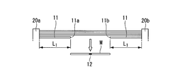
- ⁇ Repair method for leaking hollow fiber membrane module> Cutting process: First, as shown in FIG. 2A, a part of the length direction including the leak portion 12 is cut out from the hollow fiber membrane 11 in which the leak portion 12 is generated. In FIG. 2A, a hollow fiber membrane in which a symbol M is cut off. Thereby, two opening end surfaces 11a and 11b are generated. The hollow fiber membrane is preferably cut perpendicular to the length direction. Thereby, the adhesive strength of a sealing part improves and repair defect can be reduced. Sealing process: Following the cutting step, as shown in FIG.
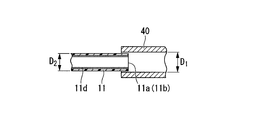
- a nozzle 40 having an inner diameter larger than the outer diameter of the hollow fiber membrane 11 is connected to a commercially available gun-type melt coating machine, and the tip of the nozzle 40 is connected.
- the opening end face 11a (11b) of the hollow fiber membrane 11 is inserted.
- a support 11d is formed inside the hollow fiber membrane.
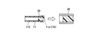
- a molten hot melt adhesive 50 is injected into the hollow fiber membrane 11 from the tip of the nozzle 40.
- FIG. 2D when the nozzle 40 is pulled out from the hollow fiber membrane 11, the injected hot melt adhesive 50 is cooled and solidified. Thereby, the opening end surface 11a (11b) of the hollow fiber membrane 11 is closed.
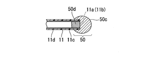
- the hot melt adhesive 50 is discharged and adhered to the outer peripheral surface 11c of the hollow fiber membrane 11 continuous with the closed open end surfaces 11a and 11b while making the tip of the nozzle 40 make one turn.
- the hot melt adhesive 50 not only covers the opening end surface 11a (11b), but also is provided so as to extend on the outer peripheral surface 11c of the hollow fiber membrane 11, thereby forming the sealing portion 50, Sealing is complete.
- the sealing portion includes an extending portion 50c provided so as to extend from the opening end surface onto the outer peripheral surface of the hollow fiber membrane, and a base portion 50d embedded in the hollow fiber membrane and bonded to the support. Is preferred. Such sealing is performed on each of the two open end faces 11a and 11b that are opened.
- the length L 1 of the hollow fiber membrane from the open end faces 11a and 11b newly opened by excision to the housings 20a and 20b is within a range of 10 to 100 mm. It is preferable that it is within a range of 5 to 50 mm.
- L 1 is 10 mm or more, during the operation of sealing the open end faces 11a and 11b with the hot melt adhesive 50, the hollow fiber membrane 11 can be repaired by suppressing the bending of the root thereof. Troubles such as damage to the base of 11 hardly occur.
- L 1 is less than 100 mm
- L 1 is in the range of 10 ⁇ 100 mm.
- the inner diameter D 1 of the nozzle 40 shown in Figure 2B preferably about 0.1 ⁇ 1 mm larger than the outer diameter D 2 of the hollow fiber membrane 11, and more preferably about 0.3 ⁇ 0.75 mm larger.
- the open end face of the hollow fiber membrane 11 can be smoothly inserted into the tip of the nozzle 40, and the hot melt adhesive 50 is unlikely to leak from the gap between the nozzle 40 and the hollow fiber membrane 11 during injection.
- the injection amount of the hot melt adhesive 50 may be an amount that the strength of the repaired portion is enough, the filling length L 2 from the opening end face 11a (11b) shown in FIG. 2C, the hollow fiber membranes 11 An amount that is 1 to 5 times the inner diameter of the is suitable.
- the hot melt adhesive 50 preferably has the same melting point as that of the resin constituting the support 11d and the resin constituting the hollow fiber membrane 11, specifically, about 100 to 250 ° C.
- a hot-melt adhesive 50 having a melting point is preferable, about 180 to 230 ° C. is more preferable, and about 120 to 200 ° C. is particularly preferable.
- Such a hot-melt adhesive 50 melts sufficiently without causing a high temperature so as to damage the support 11d and the hollow fiber membrane 11, and adheres well to the support 11d and the hollow fiber membrane 11. To do.
- the melting points of polyethylene, polypropylene, and polyvinylidene fluoride that are preferably used as the material of the hollow fiber membrane 11 are about 100 to 130 ° C., about 150 to 180 ° C., and about 150 to 210 ° C., respectively. Therefore, what is necessary is just to select the kind of hot-melt-adhesive 50 suitably according to melting
- the melt viscosity of the hot melt adhesive 50 is preferably 500 to 10,000 mPa ⁇ s.
- the pressure is 500 mPa ⁇ s or more, troubles such as the molten hot melt adhesive 50 dripping and adhering to an undesired portion hardly occur.
- it is 10000 mPa ⁇ s or less, the viscosity of the melted hot melt adhesive 50 is not too high, and therefore adheres as desired on the support 11d, the open end faces 11a and 11b of the hollow fiber membrane 11 and the outer peripheral face 11c. Can be made.
- melt viscosity means the viscosity in the molten state of a hot melt adhesive.
- EVA ethylene vinyl acetate copolymer
- PO polyolefin
- PA polyamide
- SR synthetic rubber
- ACR acrylic
- PUR polyurethane
- the leak repair method for a hollow fiber membrane in the first aspect of the present invention is preferably applied to a hollow fiber membrane having a support therein.
- the presence of the support makes it difficult for repair defects due to heat shrinkage of the hollow fiber membrane to occur, and when the hollow fiber membrane is heated and melted, the shape of the hollow fiber is easily maintained and the membrane is not easily crushed.
- the melting point of the support is preferably about the same as or lower than the melting point of the resin constituting the hollow fiber membrane 11.
- the material for the support include polyolefin resins such as polyethylene resin and polyester resin, polypropylene resin, and the like, and polyester resin is particularly preferable.
- the leak portion 12 can be repaired in a short time of several seconds to several minutes. it can. Further, since the hot melt adhesive 50 is solidified in such a short time, the sealing portion is prevented so that the hot melt adhesive 50 applied to the sealing portion does not adhere to other hollow fiber membranes 11. It takes only a short time to keep them away from the other hollow fiber membranes 11, and the workability is excellent.
- a leak part repairing method instead of sealing the end of the hollow fiber membrane in which the leak part has occurred, a part of the length of the hollow fiber membrane 11 is cut out so as to include the leak part 12 Thereafter, since the open end faces 11a and 11b opened by excision are sealed, the hollow fiber membrane 11 remaining after excision maintains the filtration function. Therefore, leak portions 12 occur in many of the hollow fiber membranes 11 constituting the hollow fiber membrane module 10A, and even if repairs are performed on each of them, the reduction in the effective membrane area as a whole of the hollow fiber membrane module 10A is suppressed to a small level. Can do.
- the hollow fiber membrane module in a form in which the end portion of the hollow fiber membrane cannot be exposed is not at all. It can be applied without problems.
- the sealing property Will be improved.
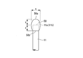
- the outer shape of the sealing portion formed of the hot melt adhesive 50 for example, as shown in FIG. 3A, the diameter gradually increases from the distal end portion 50a to the proximal end portion 50b, and then gradually decreases.
- the base end 50b side has a smaller diameter than the sealing tip end 50a side, and as shown in FIG. 3C, the sealing part tip end 50a side. Examples include a shape having a larger diameter on the base end 50b side.
- the maximum diameter x of the sealing portion is preferably at least one time as large as the outer diameter of the hollow fiber membrane 11, and more preferably 1 to 2 times. When it is 2 times or less, the sealing portion is not easily caught by other hollow fiber membranes 11, and damage to the hollow fiber membranes 11 caused by the catch can be prevented. On the other hand, when the ratio is 1 or more, the outer peripheral surface 11c of the hollow fiber membrane 11 is reinforced by the hot melt layer, so that the durability of the sealing portion is enhanced.
- the length y from the front end portion 50a of the sealing portion to the position of the open end surface 11a (11b) of the hollow fiber membrane 11 is not particularly limited. It is about the outer diameter of the film 11. Specifically, the length y from the tip of the extending portion to the position of the open end face of the hollow fiber membrane is preferably 0.1 to 0.5 times the outer diameter of the hollow fiber membrane, It is more preferably 15 to 0.35 times.
- the portion from the base end portion 50b of the sealing portion to the open end face 11a (11b) of the hollow fiber membrane 11 is formed by discharging a hot melt adhesive while the tip of the nozzle circulates around the outer periphery of the hollow fiber membrane.
- the length z substantially corresponds to the inner diameter of the nozzle 40.
- the length z from the base end portion of the extending portion to the open end surface of the hollow fiber membrane is preferably 0.5 to 1.5 times the outer diameter of the hollow fiber membrane, and 75 to 1.2 times is more preferable.
- the hot melt adhesive 50 may be applied so that the number of times of circulation is two or more and the length z is larger than the inner diameter of the nozzle 40, but in this case, the hot melt adhesive 50 in a molten state is applied. As a result, a large amount of heat is transmitted to the hollow fiber membrane 11, which may cause repair failures.
- a hollow fiber membrane in which a part of the hollow fiber membrane 11 including the leak portion 12 in the length direction is excised and the two open end faces 11a and 11b opened by the excision are sealed with the hot melt adhesive 50.
- the leak section 12 can be repaired in a short time and without a significant decrease in the effective membrane area with respect to various forms of hollow fiber membrane modules.
- the hollow fiber membrane module in the 1st side surface of this invention is a hollow fiber membrane module repaired with the above-mentioned leak part repair method, Comprising: It is a hollow fiber membrane module which has a sealing part.
- the sealing part is the same as the sealing part formed by the leak part repairing method described above.
- the leak repairing method for the hollow fiber membrane module according to the second aspect of the present invention is the same as the first aspect of the present invention except that the hollow fiber membrane does not have a support as shown in FIG. 2F. It is a method.
- the hollow fiber membrane module according to the second aspect of the present invention is the same hollow fiber membrane module as that of the first aspect of the present invention, except that the hollow fiber membrane does not have a support.
- the form of the hollow fiber membrane module to be repaired is not limited.
- only the filtered water collected in the upper housing 20 a is taken out from the water inlet 21 without having a water conduit.
- the hollow fiber membrane module 10B can also be illustrated.
- only the open end surface 11a that communicates with the upper housing 20a where the filtrate is collected may be sealed with the hot melt adhesive 50.
- the open end surface 11b on the lower housing 20b side that is not in communication with the upper housing 20a may not be sealed.
- the hollow fiber membrane module 10B of this form even if the opening end surface 11b is open, the raw water is not mixed into the treated water side. As long as the raw water is not mixed into the treated water side from the opening end face in this way, only one of the two opening end faces opened by excision may be sealed and the other may be opened. It can select suitably according to the form.
- the hollow fiber membrane is cut to expose the opening end face, and the outer surface near the tip and the sealing part are provided at the tip.
- the outer surface outer periphery of the hollow fiber membrane including the leak portion may be directly covered with a hot melt resin in a ring shape without cutting the yarn membrane.
- a hollow fiber membrane module 10A having the configuration shown in FIG. 1 was manufactured using 1560 PVDF hollow fiber membranes having a pore diameter of 0.1 ⁇ m, an outer diameter of 2.8 mm, and an inner diameter of 1.5 mm.
- the hollow fiber membrane 11 is fixed to each housing 20a, 20b with urethane resin.
- Square pipes were used for the water conduits 30a and 30b.
- the outer diameter dimensions of the hollow fiber membrane module 10A were a width W1250 mm, a height H2000 mm, and a depth D30 mm.
- the leak portion was repaired in accordance with the method shown in FIGS. 2A to 2F.
- the hollow fiber membrane module 10A of FIG. 1 that has been repaired in this manner is immersed in a 30% strength aqueous alcohol solution to perform a hydrophilic treatment, and then transferred into water, and the hollow fiber membrane module 10A of the hollow fiber membrane module 10A is removed from the water intake 21. Air was supplied so that the internal pressure was 100 kPa, and a leak test was performed. In the leak test, no air leakage was confirmed from the hollow fiber membrane module 10A, and it was confirmed that all the open end faces 11a and 11b of the hollow fiber membrane 11 were sealed.
- 10A, 10B Hollow fiber membrane module 11: Hollow fiber membrane 11a, 11b: Open end surface of hollow fiber membrane 11d: Support 11c: Outer peripheral surface of hollow fiber membrane 12: Leakage part 50: Hot melt adhesive (sealing part) 50a: distal end portion 50b: base end portion 50c: extension portion 50d: base portion
Landscapes
- Chemical & Material Sciences (AREA)
- Chemical Kinetics & Catalysis (AREA)
- Separation Using Semi-Permeable Membranes (AREA)
Abstract
本発明は、中空糸膜モジュールのリーク部補修方法であって、前記中空糸膜モジュールが、複数本の中空糸膜を備え、前記中空糸膜が、その内部に支持体を有しており、前記中空糸膜のリーク部を含む外表面に封止部を形成することにより封止する封止工程を含む、中空糸膜モジュールのリーク部補修方法、および前記リーク部補修方法により補修された中空糸膜モジュールであって、封止部を有する中空糸膜モジュールに関する。
Description
本発明は、水処理などに用いられる中空糸膜モジュールのリーク部補修方法および中空糸膜モジュールに関する。
本願は、2011年4月28日に、日本に出願された特願2011-102025号に基づき優先権を主張し、その内容をここに援用する。
本願は、2011年4月28日に、日本に出願された特願2011-102025号に基づき優先権を主張し、その内容をここに援用する。
各種水処理などには、複数本の中空糸膜を備えた中空糸膜モジュールが広く使用されている。中空糸膜モジュールにおいては、中空糸膜に穴が開いたり破断が生じたりして、そこから原水が処理水側に漏れてしまうことがある。そこで、例えば特許文献1や特許文献2に記載された中空糸膜のリーク検査方法を用いて、リークの有無及びリーク部の特定を行う方法が知られている。
一方、検知されたリーク部を補修する方法としては、ウレタン樹脂、エポキシ樹脂などの熱硬化性樹脂を用いて補修する方法がある。
一方、検知されたリーク部を補修する方法としては、ウレタン樹脂、エポキシ樹脂などの熱硬化性樹脂を用いて補修する方法がある。
ところが、このように熱硬化性樹脂を用いてリーク部を補修する場合には、補修部分に付与された熱硬化性樹脂が他の中空糸膜に付着してしまわないように、補修部分を他の中空糸膜から離しておく必要があり作業性が悪い。
そこで、短時間で冷却固化するホットメルト接着剤を用いて、リーク部を補修する方法が検討されている。
そこで、短時間で冷却固化するホットメルト接着剤を用いて、リーク部を補修する方法が検討されている。
例えば、特許文献3の図3には、破断が生じた中空糸膜の端部に、溶融したホットメルト接着剤を埋め込む方法が記載されている。
しかしながら、中空糸膜モジュールにおける中空糸膜の端部には、通常、集水用のハウジングが装着されていて、中空糸膜の端部は露出していない。そのため、特許文献3のように、中空糸膜の端部に対してホットメルト接着剤を埋め込む方法は、ハウジングに開閉自在なカバーなどが設けられていて、中空糸膜の端部を露出させ得る形態の中空糸膜モジュールに対しては適用できても、中空糸膜の端部を露出させることができない形態の中空糸膜モジュールには適用できない。
また、特許文献3に記載のように、中空糸膜の端部を閉塞する方法では、端部が閉塞された中空糸膜はその全長に亘って濾過機能を失ってしまう。そのため、このような方法で補修された中空糸膜の本数が多いと、中空糸膜モジュールとしての有効膜面積が大きく低下するという問題もある。
本発明は上記事情に鑑みてなされたもので、種々の形態の中空糸膜モジュールに対して、短時間で、かつ、有効膜面積の大きな低下を伴うことなく、リーク部を補修できる中空糸膜モジュールのリーク部補修方法の提供、および前記リーク部補修方法により補修された中空糸膜モジュールの提供を課題とする。
本発明の第一の側面は、以下の側面を有する。
[1]中空糸膜モジュールのリーク部補修方法であって、前記中空糸膜モジュールが、複数本の中空糸膜を備え、前記中空糸膜が、その内部に支持体を有しており、前記中空糸膜のリーク部を含む外表面に封止部を形成することにより封止する封止工程を含む、中空糸膜モジュールのリーク部補修方法。
[2]前記リーク部を含む前記中空糸膜の長さ方向の一部分を切除する切除工程と、切除により開口した前記中空糸膜の開口端面付近の外表面及び開口端面に封止部を形成することにより封止する封止工程とを含む、[1]に記載の中空糸膜モジュールのリーク部補修方法。
上記構成を有することにより、短時間で、有効面積を大きく損なうことなくリーク部を補修できる。また、支持体があることで中空糸膜の熱収縮に起因する補修不良が起こりにくく、中空糸膜が加熱溶融されるときに中空糸の形状を保持しやすく膜がつぶれにくい。
[3]前記封止工程が、切除により開口した前記中空糸膜の開口端面付近の外表面及び開口端面に、ホットメルト接着剤を、180~230℃に加熱して前記封止部を形成することにより行われる、[2]に記載の中空糸膜モジュールのリーク部補修方法。
上記構成を有することにより、180~230℃に加熱したホットメルト接着剤の熱により、中空糸膜が融解するため、ホットメルト接着剤との接着力を高めることができる。
[4]前記ホットメルト接着剤がポリオレフィン系樹脂からなり、前記支持体がポリエステル樹脂からなる、[3]に記載の中空糸膜モジュールのリーク部補修方法。
上記構成を有することにより、ポリオレフィン系樹脂およびポリエステル樹脂の融点はそれぞれ100~180℃の範囲であるため、一般的な中空糸膜の融点の範囲と近い。このため、ホットメルト接着剤の融点以上に過加熱しなくても、中空糸膜を融解して接着させることができるため、ホットメルト接着剤の熱分解等の弊害を抑制できる。また、ポリオレフィン系樹脂およびポリエステル樹脂は、弾性率が小さく柔軟性に優れているので、中空糸膜の屈曲による補修部への応力集中が起こり難く、溶融粘度も良好で、接着強度に優れ、耐薬品性にも優れる。
[5]前記封止部が、前記開口端面から前記中空糸膜の外周面上に延出するように設けられた延出部と、中空糸膜内部に埋設され前記支持体と接着する基部とから形成される、[2]~[4]のいずれか一項に記載の中空糸膜モジュールのリーク部補修方法。
上記構成を有することにより、基部において支持体と接着させることによって、接着面が形成しにくい開口端面においても強固な接着性を確保できる。
[6]前記中空糸膜がポリフッ化ビニリデンからなる、[2]~[5]のいずれか一項に記載の中空糸膜モジュールのリーク部補修方法。
上記構成を有することにより、ポリフッ化ビニリデンはフッ素系の樹脂であるため、上記方法により得られる中空糸膜モジュールは耐薬品性に優れている。
[7]前記延出部の最大径xが、前記中空糸膜の外径の1~2倍となるように形成される、[5]又は[6]に記載の中空糸膜モジュールのリーク部補修方法。
上記構成とすることにより、封止部が耐久性に優れるととに、隣接した中空糸膜に引っかかりにくい。
[8]前記延出部の先端部から前記中空糸膜の開口端面の位置までの長さyが、前記中空糸膜の外径の0.1~0.5倍となるように形成される、[5]~[7]のいずれか一項に記載の中空糸膜モジュールのリーク部補修方法。
上記構成とすることにより、封止部が耐圧性に優れるとともに、過剰に接着剤を消費しない。
[9]前記延出部の前記基端部から前記中空糸膜の開口端面までの長さzが、前記中空糸膜の外径の0.5~1.5倍となるように形成される、[5]~[8]のいずれか一項に記載の中空糸膜モジュールのリーク部補修方法。
上記構成とすることにより、封止部の接着強度が向上し、補修不良を低減させることができる。
[10][1]~[9]のいずれか1項に記載のリーク部補修方法により補修された中空糸膜モジュールであって、封止部を有する中空糸膜モジュール。
上記構成とすることにより、有効面積を大きく損なうことなくリーク部が補修された中空糸膜モジュールを提供することができる。
また、本発明の第二の側面は、以下の側面を有する。
[1]複数本の中空糸膜を備えた中空糸膜モジュールの前記中空糸膜に生じたリーク部を補修する方法であって、前記リーク部を含む前記中空糸膜の長さ方向の一部分を切除する切断工程と、切除により開口した前記中空糸膜の開口端面をホットメルト接着剤で封止して封止部を形成する封止工程とを含む、中空糸膜モジュールのリーク部補修方法。
[2]複数本の中空糸膜を備えた中空糸膜モジュールであって、少なくとも1本の中空糸膜の長さ方向の一部分が切除され、切除により開口した2つの開口端面のうち少なくとも一つがホットメルト接着剤で封止されている封止部を有する、中空糸膜モジュール。
[3]前記封止部は、前記開口端面から前記中空糸膜の外周面上に延出するように設けられている、[2]に記載の中空糸膜モジュール。
[1]複数本の中空糸膜を備えた中空糸膜モジュールの前記中空糸膜に生じたリーク部を補修する方法であって、前記リーク部を含む前記中空糸膜の長さ方向の一部分を切除する切断工程と、切除により開口した前記中空糸膜の開口端面をホットメルト接着剤で封止して封止部を形成する封止工程とを含む、中空糸膜モジュールのリーク部補修方法。
[2]複数本の中空糸膜を備えた中空糸膜モジュールであって、少なくとも1本の中空糸膜の長さ方向の一部分が切除され、切除により開口した2つの開口端面のうち少なくとも一つがホットメルト接着剤で封止されている封止部を有する、中空糸膜モジュール。
[3]前記封止部は、前記開口端面から前記中空糸膜の外周面上に延出するように設けられている、[2]に記載の中空糸膜モジュール。
本発明によれば、種々の形態の中空糸膜モジュールに対して、短時間で、かつ、有効膜面積の大きな低下を伴うことなく、リーク部を補修できる。
以下、本発明について詳細に説明する。
図1は、本発明の中空糸膜モジュールの一例を示す斜視図である。
この中空糸膜モジュール10Aは、シート状に配列された複数本の中空糸膜11と、中空糸膜11の長さ方向の両端部に設けられた2本の集水用のハウジング20a,および20bとを備えている。各中空糸膜11の両端部は開口した状態で、ウレタン樹脂などによりハウジング20a,および20b内に固定され、中空糸膜11とハウジング20a,および20b内の流路とが連通している。
図1は、本発明の中空糸膜モジュールの一例を示す斜視図である。
この中空糸膜モジュール10Aは、シート状に配列された複数本の中空糸膜11と、中空糸膜11の長さ方向の両端部に設けられた2本の集水用のハウジング20a,および20bとを備えている。各中空糸膜11の両端部は開口した状態で、ウレタン樹脂などによりハウジング20a,および20b内に固定され、中空糸膜11とハウジング20a,および20b内の流路とが連通している。
また、この例の中空糸膜モジュール10Aは、2本のハウジング20a,および20bを連通する2本の導水管30a,および30bを備えていて、一方のハウジング(上側ハウジング)20aの長さ方向の端部に、濾過水を得る取水口21が形成されている。そのため、この中空糸膜モジュール10Aで原水を吸引濾過した際には、他方のハウジング(下側ハウジング)20bに集められた濾過水が導水管30a,および30bを通って上側ハウジング20aへと集められ、取水口21からは、上側ハウジング20aと下側ハウジング20bに集められた濾過水が取り出せるようになっている。
中空糸膜11の材質としては、例えば、ポリエチレン(融点:100~130℃程度)やポリプロピレン(融点:150~180℃程度)などのポリオレフィン、ポリフッ化ビニリデン(PVDF、融点:150~210℃程度)やポリテトラフルオロエチレンなどのフッ素系樹脂、ポリスルホン系樹脂、ポリアクリロニトリル、セルロース誘導体、ポリアミド、ポリエステル、ポリメタクリレート、およびポリアクリレートなども挙げられる。これらのうち1種以上を含む樹脂を使用できる。また、これらの樹脂の共重合体や一部に置換基を導入したものであってもよい。なかでもポリフッ化ビニリデンが、耐薬品性に優れているため好ましい。
ハウジング20a,および20bおよび導水管30a,および30bの材質としては、機械的強度および耐久性を有するものが好適に用いられ、例えばポリカーボネート、ポリスルホン、ポリオレフィン、PVC(ポリ塩化ビニル)、アクリル樹脂、ABS樹脂、および変成PPE(ポリフェニレンエーテル)などが挙げられ、これらのうち1種以上を含む樹脂を使用できる。あるいは、ステンレス、およびチタンなどの耐腐食性金属を用いてもよい。
そして、図1の中空糸膜モジュール10Aは、図1中に拡大して示すように、多数の中空糸膜11のうちの1本において、長さ方向の一部分が切り取られ、このような切除により新たに開口した2つの開口端面11a,および11bがホットメルト接着剤50で封止されている。具体的には、この中空糸膜モジュール10Aは、1本の中空糸膜11においてリーク穴(リーク部)が生じ、このリーク部を含むように中空糸膜11の長さ方向の一部分が切除され、切除により開口した2つの開口端面11a,11bがホットメルト接着剤50で封止されるリーク部補修がなされたものである。
なお、リーク部の特定は、リーク部位が特定可能なリーク検査方法、例えば、水や界面活性剤などの液体中に浸漬した膜内部に気体を送り込み、気泡の発生状況によりリーク部を特定する方法や、着色液などの着色流体を流し込み、着色の有無でリーク部を特定する方法などを用いることができる。
なお、リーク部の特定は、リーク部位が特定可能なリーク検査方法、例えば、水や界面活性剤などの液体中に浸漬した膜内部に気体を送り込み、気泡の発生状況によりリーク部を特定する方法や、着色液などの着色流体を流し込み、着色の有無でリーク部を特定する方法などを用いることができる。
このようなリーク部補修は、例えば図2A~2Eに示すように行う。
以下、本発明の第一の側面について説明する。
<中空糸膜モジュールのリーク部補修方法>
切断工程:
まず、図2Aに示すように、リーク部12が生じた中空糸膜11から、リーク部12を含む長さ方向の一部分を切除する。図2A中、符号Mが切除された中空糸膜である。これにより2つの開口端面11a,および11bが生じる。
中空糸膜は、長さ方向に対して垂直に切断されることが好ましい。これにより、封止部の接着強度が向上し、補修不良を低減させることができる。
封止工程:
切断工程についで、図2Bに示すように、市販されているガンタイプの溶融塗布機に、中空糸膜11の外径よりも大きな内径を備えたノズル40を接続し、そのノズル40の先端に中空糸膜11の開口端面11a(11b)を挿入する。なお、中空糸膜の内側には支持体11dが形成されている。そして、図2Cに示すように、ノズル40の先端から中空糸膜11に、溶融したホットメルト接着剤50を注入する。注入後、図2Dに示すように、ノズル40を中空糸膜11から引き抜くと、注入されたホットメルト接着剤50は冷えて固化する。これにより、中空糸膜11の開口端面11a(11b)が閉塞される。その後、閉塞された開口端面11a,および11bに連続している中空糸膜11の外周面11c上にノズル40の先端を1周させつつホットメルト接着剤50を吐出し付着させることにより、図2Eに示すように、ホットメルト接着剤50は開口端面11a(11b)を覆うだけでなく、中空糸膜11の外周面11c上に延出するように設けられることにより封止部50を形成し、封止が完了する。封止部は、開口端面から中空糸膜の外周面上に延出するように設けられている延出部50cと、中空糸膜内部に埋設され前記支持体と接着する基部50dとからなることが好ましい。このような封止を開口した2つの開口端面11a,および11bに対してそれぞれ行う。
以下、本発明の第一の側面について説明する。
<中空糸膜モジュールのリーク部補修方法>
切断工程:
まず、図2Aに示すように、リーク部12が生じた中空糸膜11から、リーク部12を含む長さ方向の一部分を切除する。図2A中、符号Mが切除された中空糸膜である。これにより2つの開口端面11a,および11bが生じる。
中空糸膜は、長さ方向に対して垂直に切断されることが好ましい。これにより、封止部の接着強度が向上し、補修不良を低減させることができる。
封止工程:
切断工程についで、図2Bに示すように、市販されているガンタイプの溶融塗布機に、中空糸膜11の外径よりも大きな内径を備えたノズル40を接続し、そのノズル40の先端に中空糸膜11の開口端面11a(11b)を挿入する。なお、中空糸膜の内側には支持体11dが形成されている。そして、図2Cに示すように、ノズル40の先端から中空糸膜11に、溶融したホットメルト接着剤50を注入する。注入後、図2Dに示すように、ノズル40を中空糸膜11から引き抜くと、注入されたホットメルト接着剤50は冷えて固化する。これにより、中空糸膜11の開口端面11a(11b)が閉塞される。その後、閉塞された開口端面11a,および11bに連続している中空糸膜11の外周面11c上にノズル40の先端を1周させつつホットメルト接着剤50を吐出し付着させることにより、図2Eに示すように、ホットメルト接着剤50は開口端面11a(11b)を覆うだけでなく、中空糸膜11の外周面11c上に延出するように設けられることにより封止部50を形成し、封止が完了する。封止部は、開口端面から中空糸膜の外周面上に延出するように設けられている延出部50cと、中空糸膜内部に埋設され前記支持体と接着する基部50dとからなることが好ましい。このような封止を開口した2つの開口端面11a,および11bに対してそれぞれ行う。
ここで図2Aに示すように、切除により新たに開口した開口端面11a,および11bから、各ハウジング20a,および20bに至るまでの中空糸膜の長さL1は、10~100mmの範囲内であることが好ましく、より好ましくは5~50mmの範囲内である。L1が10mm以上であると、ホットメルト接着剤50で開口端面11a,および11bを封止する作業中に、この中空糸膜11の根元の屈曲を抑制して補修を行えるので、中空糸膜11の根元が損傷するなどのトラブルが起こりにくい。一方、L1が100mm未満であると、補修後の中空糸膜モジュール10Aを例えば被処理水槽に浸漬してエアスクラビング処理を行った際に、補修した中空糸膜11が過度に揺動しにくい。そのため、過度に揺動することによる他の中空糸膜11と擦れや、根元の大きな屈曲が抑制され、それによる中空糸膜11の損傷が防止される。リーク部12を含む長さ方向の一部分を切除する際には、以上の点を考慮して、L1が10~100mmの範囲内となるように切除位置を決定することが好ましい。
また、図2Bに示すノズル40の内径D1は、中空糸膜11の外径D2よりも0.1~1mm程度大きいことが好ましく、0.3~0.75mm程度大きいことがより好ましい。このような範囲であると、ノズル40の先端に中空糸膜11の開口端面をスムーズに挿入でき、かつ、注入時に、ノズル40と中空糸膜11の隙間からホットメルト接着剤50が漏れにくい。
また、ホットメルト接着剤50の注入量は、補修部分の強度が充分となる量であればよいが、図2Cに示す開口端面11a(11b)からの充填長さL2が、中空糸膜11の内径の1~5倍となる量が適当である。
また、ホットメルト接着剤50の注入量は、補修部分の強度が充分となる量であればよいが、図2Cに示す開口端面11a(11b)からの充填長さL2が、中空糸膜11の内径の1~5倍となる量が適当である。
ホットメルト接着剤50としては、支持体11dを構成している樹脂および中空糸膜11を構成している樹脂と同程度の融点を有するものが好ましく、具体的には、100~250℃程度の融点のホットメルト接着剤50が好ましく、180~230℃程度がより好ましく120~200℃程度のものが特に好ましい。このようなホットメルト接着剤50であると、支持体11dおよび中空糸膜11にダメージを与えるほどの高温にしなくても充分に溶融し、かつ、支持体11dおよび中空糸膜11に良好に付着する。
なお、上記したように、中空糸膜11の材料として好適に用いられるポリエチレン、ポリプロピレン、ポリフッ化ビニリデンの融点は、それぞれ100~130℃程度、150~180℃程度、150~210℃程度である。そのため、中空糸膜11を構成している樹脂の融点に応じて、ホットメルト接着剤50の種類も適宜選択すればよい。
なお、上記したように、中空糸膜11の材料として好適に用いられるポリエチレン、ポリプロピレン、ポリフッ化ビニリデンの融点は、それぞれ100~130℃程度、150~180℃程度、150~210℃程度である。そのため、中空糸膜11を構成している樹脂の融点に応じて、ホットメルト接着剤50の種類も適宜選択すればよい。
ホットメルト接着剤50の溶融粘度は、500~10000mPa・sであるものが好ましい。500mPa・s以上であると、溶融したホットメルト接着剤50が目的外の部分まで垂れて付着するなどのトラブルが生じにくい。また、10000mPa・s以下であると、溶融したホットメルト接着剤50の粘度が高すぎず、そのため、支持体11d、中空糸膜11の開口端面11a,および11bや外周面11c上に所望どおり付着させることができる。なお、溶融粘度とは、ホットメルト接着剤の溶融状態における粘度を意味する。
具体的には、ホットメルト接着剤50としては、EVA(エチレン酢酸ビニル共重合体)系樹脂、PO(ポリオレフィン)系樹脂、PA(ポリアミド)系樹脂、SR(合成ゴム)系樹脂、ACR(アクリル)系樹脂、PUR(ポリウレタン)系樹脂などが挙げられる。なかでも、耐薬品性に優れ、かつ、廃棄時に燃焼させたとしても、有害ガスが発生しにくいPO系樹脂が好ましい。
本発明の第一の側面における中空糸膜のリーク部補修方法は、その内部に支持体を有する中空糸膜に適用することが好ましい。支持体があることで中空糸膜の熱収縮に起因する補修不良が起こりにくく、中空糸膜が加熱溶融されるときに中空糸の形状を保持しやすく膜がつぶれにくい。支持体の融点としては、中空糸膜11を構成している樹脂の融点と同程度かそれ以下が好ましい。
支持体の材料としては、ポリエチレン樹脂やポリエステル樹脂等のポリオレフィン樹脂、ポリプロピレン樹脂等が挙げられ、なかでもポリエステル樹脂が好ましい。このような材料を用い、さらにホットメルト接着剤としてPO樹脂をもちいることにより、化学的接着性が良好な組む見合わせとなり接着性をより向上させるができる。
支持体の材料としては、ポリエチレン樹脂やポリエステル樹脂等のポリオレフィン樹脂、ポリプロピレン樹脂等が挙げられ、なかでもポリエステル樹脂が好ましい。このような材料を用い、さらにホットメルト接着剤としてPO樹脂をもちいることにより、化学的接着性が良好な組む見合わせとなり接着性をより向上させるができる。
このようなリーク部補修方法によれば、長時間を要せずに固化するホットメルト接着剤50を用いているため、例えば数秒間から数分間という短時間で、リーク部12を補修することができる。また、ホットメルト接着剤50は、このように短時間で固化するため、封止部に付与されたホットメルト接着剤50が他の中空糸膜11に付着してしまわないように、封止部を他の中空糸膜11から離しておく時間も短くてすみ、作業性に優れる。
また、このようなリーク部補修方法では、リーク部が生じた中空糸膜の端部を封止するのではなく、リーク部12を含むように中空糸膜11の長さ方向の一部分を切除した後、切除により開口した開口端面11a,および11bを封止しているため、切除後に残った中空糸膜11は濾過機能を維持する。そのため、中空糸膜モジュール10Aを構成する中空糸膜11の多数においてリーク部12が生じ、それぞれに対して補修をしたとしても、中空糸膜モジュール10A全体としての有効膜面積の低下を小さく抑えることができる。ここで仮に、リーク部が生じた中空糸膜の端部を封止する方法を採用すると、リーク部が生じた多数の中空糸膜のすべてが、その全長に亘って濾過機能を失うため、中空糸膜モジュールとしての有効膜面積が大きく低下してしまう。
また、このようなリーク部補修方法は、中空糸膜の端部を封止する方法ではないため、中空糸膜の端部を露出させることができない形態の中空糸膜モジュールに対しても、何ら問題なく適用できる。
また、この例のように、ホットメルト接着剤50を中空糸膜11の開口端面11a,11bだけでなく、中空糸膜11の外周面11c上にまで延出するように設けると、封止性がより向上する。
ホットメルト接着剤50で形成された封止部の外形としては、例えば、図3Aに示すように、封止部の先端部50aから基端部50bまで、径が漸次大きくなった後、漸次小さくなる形状、図3Bに示すように、封止部の先端部50a側よりも基端部50b側の方が径が小さい形状、図3Cに示すように、封止部の先端部50a側よりも基端部50b側の方が径が大きい形状などが挙げられる。
ホットメルト接着剤50で形成された封止部の外形としては、例えば、図3Aに示すように、封止部の先端部50aから基端部50bまで、径が漸次大きくなった後、漸次小さくなる形状、図3Bに示すように、封止部の先端部50a側よりも基端部50b側の方が径が小さい形状、図3Cに示すように、封止部の先端部50a側よりも基端部50b側の方が径が大きい形状などが挙げられる。
また、これらの各形状において、封止部の最大径xは、中空糸膜11の外径の1倍以上が好ましく、1~2倍がより好ましい。2倍以下であると、封止部が他の中空糸膜11に引っ掛かりにくく、引っ掛かりにより生じる中空糸膜11の損傷を防止できる。一方、1倍以上であると、中空糸膜11の外周面11cがホットメルトの層で補強されるので、封止部の耐久性が高まる。
封止部の先端部50aから中空糸膜11の開口端面11a(11b)の位置までの長さyは、特に制限はないが、ホットメルト接着剤50の溶融時の表面張力などから、中空糸膜11の外径程度である。具体的には、延出部の先端部から中空糸膜の開口端面の位置までの長さyが、中空糸膜の外径の0.1~0.5倍であることが好ましく、0.15~0.35倍であることがより好ましい。
封止部の基端部50bから中空糸膜11の開口端面11a(11b)までの部分は、ノズルの先端を中空糸膜の外周に周回させつつホットメルト接着剤を吐出することで形成される部分であるため、ノズル40を周回させる回数が1回である場合には、その長さzは、ノズル40の内径にほぼ相当する。具体的には、延出部の基端部から中空糸膜の開口端面までの長さzが、前記中空糸膜の外径の0.5~1.5倍であることが好ましく、0.75~1.2倍がより好ましい。周回させる回数を2回以上として、長さzがノズル40の内径よりも大きくなるようにホットメルト接着剤50を塗布してもよいが、その際には、溶融状態にあるホットメルト接着剤50の熱が中空糸膜11により多く伝わる結果、補修不良が生じる可能性がある。
封止部の基端部50bから中空糸膜11の開口端面11a(11b)までの部分は、ノズルの先端を中空糸膜の外周に周回させつつホットメルト接着剤を吐出することで形成される部分であるため、ノズル40を周回させる回数が1回である場合には、その長さzは、ノズル40の内径にほぼ相当する。具体的には、延出部の基端部から中空糸膜の開口端面までの長さzが、前記中空糸膜の外径の0.5~1.5倍であることが好ましく、0.75~1.2倍がより好ましい。周回させる回数を2回以上として、長さzがノズル40の内径よりも大きくなるようにホットメルト接着剤50を塗布してもよいが、その際には、溶融状態にあるホットメルト接着剤50の熱が中空糸膜11により多く伝わる結果、補修不良が生じる可能性がある。
以上説明したように、リーク部12を含む中空糸膜11の長さ方向の一部分を切除し、切除により開口した2つの開口端面11a,および11bをホットメルト接着剤50で封止する中空糸膜モジュール10Aのリーク部補修方法によれば、種々の形態の中空糸膜モジュールに対して、短時間で、かつ、有効膜面積の大きな低下を伴うことなく、リーク部12を補修できる。
<中空糸膜モジュール>
本発明の第一の側面における中空糸膜モジュールは、上述のリーク部補修方法により補修された中空糸膜モジュールであって、封止部を有する中空糸膜モジュールである。封止部は、上述のリーク部補修方法により形成された封止部と同様のものである。
本発明の第一の側面における中空糸膜モジュールは、上述のリーク部補修方法により補修された中空糸膜モジュールであって、封止部を有する中空糸膜モジュールである。封止部は、上述のリーク部補修方法により形成された封止部と同様のものである。
次に、本発明の第二の側面について詳細に説明する。
<中空糸膜モジュールのリーク部補修方法>
本発明の第二の側面における中空糸膜モジュールのリーク部補修方法では、図2Fに示すように、中空糸膜が支持体を有しないものを用いる以外は、本発明の第一の側面と同様の方法である。
<中空糸膜モジュール>
本発明の第二の側面における中空糸膜モジュールでは、中空糸膜が支持体を有しないものを用いる以外は、本発明の第一の側面と同様の中空糸膜モジュールである。
本発明の第二の側面における中空糸膜モジュールのリーク部補修方法では、図2Fに示すように、中空糸膜が支持体を有しないものを用いる以外は、本発明の第一の側面と同様の方法である。
<中空糸膜モジュール>
本発明の第二の側面における中空糸膜モジュールでは、中空糸膜が支持体を有しないものを用いる以外は、本発明の第一の側面と同様の中空糸膜モジュールである。
なお、補修対象の中空糸膜モジュールの形態には制限はなく、例えば、図4に示すように、導水管を具備せず、上側ハウジング20aに集められた濾過水のみを取水口21から取り出す形態の中空糸膜モジュール10Bも例示できる。この場合には、リーク部を含む長さ方向の一部分を切除した後、濾過水が集水される上側ハウジング20aに連通した方の開口端面11aのみをホットメルト接着剤50で封止すればよく、上側ハウジング20aに連通していない下側ハウジング20b側の開口端面11bは封止しなくてもよい。この形態の中空糸膜モジュール10Bの場合には、開口端面11bが開放していても、原水が処理水側に混入することはない。このように原水が開口端面から処理水側に混入しないかぎりは、切除により開口した2つの開口端面のうちの一方のみを封止して、他方を開放しておいてもよく、中空糸膜モジュールの形態に応じて適宜選択できる。
また、上記実施形態においては、中空糸膜を切断して開口端面を露出させ、その先端付近の外表面および先端に封止部を設けたが、リーク部が明確に断定できる場合などは、中空糸膜を切断せずに、リーク部を含む中空糸膜の外表面外周を、直接ホットメルト樹脂でリング状に覆ってもよい。
以下、実施例を挙げて本発明を具体的に説明する。
[実施例]
孔径0.1μm、外径2.8mm、内径1.5mmのPVDF製中空糸膜を1560本用いて、図1の構成の中空糸膜モジュール10Aを製造した。中空糸膜11は各ハウジング20a,20bにウレタン樹脂で固定されている。導水管30a,30bには、角パイプを用いた。中空糸膜モジュール10Aの外径寸法は、幅W1250mm、高さH2000mm、奥行きD30mmとした。
ついで、図2A~図2Fに示す方法に沿って、リーク部補修を行った。
すなわち、10本の中空糸膜11を無作為に抽出し、両側のハウジング20a,20bからの長さL1がそれぞれ50mmとなる2箇所で各中空糸膜11をカットし、中空糸膜11の長さ方向の一部分を取り除いた。
ついで、溶融塗布機「PolygunHP」(住友3M社製)に内径3mmのノズル40を接続し、これを用いて、ホットメルト接着剤「3748-Q」(材質:PP、融点:150~180℃、溶融粘度4000mPa・s、住友3M社製)により、10本の中空糸膜11における開口端面11a(11b)を封止した。合計20箇所の封止部の外形は、いずれも図3Aに示す形状であり、各部分の長さは、x=3.0~4.5mm、y=2.8~3.5mm、z=2.5~3.5mmの範囲内であった。
このようにリーク部補修を行った図1の中空糸膜モジュール10Aを30%濃度のアルコール水溶液に浸漬して親水化処理を行った後、水中に移し、取水口21から中空糸膜モジュール10Aの内圧が100kPaとなるように空気を供給し、リーク試験を行った。
リーク試験において、中空糸膜モジュール10Aからはエア漏れが確認されず、中空糸膜11の開口端面11a,および11bは全て確実に封止されていることが確認できた。
[実施例]
孔径0.1μm、外径2.8mm、内径1.5mmのPVDF製中空糸膜を1560本用いて、図1の構成の中空糸膜モジュール10Aを製造した。中空糸膜11は各ハウジング20a,20bにウレタン樹脂で固定されている。導水管30a,30bには、角パイプを用いた。中空糸膜モジュール10Aの外径寸法は、幅W1250mm、高さH2000mm、奥行きD30mmとした。
ついで、図2A~図2Fに示す方法に沿って、リーク部補修を行った。
すなわち、10本の中空糸膜11を無作為に抽出し、両側のハウジング20a,20bからの長さL1がそれぞれ50mmとなる2箇所で各中空糸膜11をカットし、中空糸膜11の長さ方向の一部分を取り除いた。
ついで、溶融塗布機「PolygunHP」(住友3M社製)に内径3mmのノズル40を接続し、これを用いて、ホットメルト接着剤「3748-Q」(材質:PP、融点:150~180℃、溶融粘度4000mPa・s、住友3M社製)により、10本の中空糸膜11における開口端面11a(11b)を封止した。合計20箇所の封止部の外形は、いずれも図3Aに示す形状であり、各部分の長さは、x=3.0~4.5mm、y=2.8~3.5mm、z=2.5~3.5mmの範囲内であった。
このようにリーク部補修を行った図1の中空糸膜モジュール10Aを30%濃度のアルコール水溶液に浸漬して親水化処理を行った後、水中に移し、取水口21から中空糸膜モジュール10Aの内圧が100kPaとなるように空気を供給し、リーク試験を行った。
リーク試験において、中空糸膜モジュール10Aからはエア漏れが確認されず、中空糸膜11の開口端面11a,および11bは全て確実に封止されていることが確認できた。
本発明によれば、種々の形態の中空糸膜モジュールに対して、短時間で、かつ、有効膜面積の大きな低下を伴うことなく、リーク部を補修できる。
10A,10B:中空糸膜モジュール
11:中空糸膜
11a,11b:中空糸膜の開口端面
11d:支持体
11c:中空糸膜の外周面
12:リーク部
50:ホットメルト接着剤(封止部)
50a:先端部
50b:基端部
50c:延出部
50d:基部
11:中空糸膜
11a,11b:中空糸膜の開口端面
11d:支持体
11c:中空糸膜の外周面
12:リーク部
50:ホットメルト接着剤(封止部)
50a:先端部
50b:基端部
50c:延出部
50d:基部
Claims (10)
- 中空糸膜モジュールのリーク部補修方法であって、
前記中空糸膜モジュールが、複数本の中空糸膜を備え、前記中空糸膜が、その内部に支持体を有しており、
前記中空糸膜のリーク部を含む外表面に封止部を形成することにより封止する封止工程を含む、中空糸膜モジュールのリーク部補修方法。 - 前記リーク部を含む前記中空糸膜の長さ方向の一部分を切除する切除工程と、
切除により開口した前記中空糸膜の開口端面付近の外表面及び開口端面に封止部を形成することにより封止する封止工程とを含む、請求項1に記載の中空糸膜モジュールのリーク部補修方法。 - 前記封止工程が、切除により開口した前記中空糸膜の開口端面付近の外表面及び開口端面に、ホットメルト接着剤を、180~230℃に加熱して前記封止部を形成することにより行われる、請求項2に記載の中空糸膜モジュールのリーク部補修方法。
- 前記ホットメルト接着剤がポリオレフィン系樹脂からなり、前記支持体がポリエステル樹脂からなる、請求項3に記載の中空糸膜モジュールのリーク部補修方法。
- 前記封止部が、前記開口端面から前記中空糸膜の外周面上に延出するように設けられた延出部と、
中空糸膜内部に埋設され前記支持体と接着する基部とから形成される、請求項2~4のいずれか一項に記載の中空糸膜モジュールのリーク部補修方法。 - 前記中空糸膜がポリフッ化ビニリデンからなる、請求項2~5のいずれか一項に記載の中空糸膜モジュールのリーク部補修方法。
- 前記延出部の最大径xが、前記中空糸膜の外径の1~2倍となるように形成される、請求項5又は6に記載の中空糸膜モジュールのリーク部補修方法。
- 前記延出部の先端部から前記中空糸膜の開口端面の位置までの長さyが、前記中空糸膜の外径の0.1~0.5倍となるように形成される、請求項5~7のいずれか一項に記載の中空糸膜モジュールのリーク部補修方法。
- 前記延出部の前記基端部から前記中空糸膜の開口端面までの長さzが、前記中空糸膜の外径の0.5~1.5倍となるように形成される、請求項5~8のいずれか一項に記載の中空糸膜モジュールのリーク部補修方法。
- 請求項1~9のいずれか1項に記載のリーク部補修方法により補修された中空糸膜モジュールであって、
封止部を有する中空糸膜モジュール。
Priority Applications (2)
| Application Number | Priority Date | Filing Date | Title |
|---|---|---|---|
| JP2012524800A JP5609975B2 (ja) | 2011-04-28 | 2012-04-27 | 中空糸膜モジュールのリーク部補修方法および中空糸膜モジュール |
| CN201280020098.6A CN103492055B (zh) | 2011-04-28 | 2012-04-27 | 中空纤维膜组件的泄漏部位修补方法及中空纤维膜组件 |
Applications Claiming Priority (2)
| Application Number | Priority Date | Filing Date | Title |
|---|---|---|---|
| JP2011-102025 | 2011-04-28 | ||
| JP2011102025 | 2011-04-28 |
Publications (1)
| Publication Number | Publication Date |
|---|---|
| WO2012147932A1 true WO2012147932A1 (ja) | 2012-11-01 |
Family
ID=47072444
Family Applications (1)
| Application Number | Title | Priority Date | Filing Date |
|---|---|---|---|
| PCT/JP2012/061404 Ceased WO2012147932A1 (ja) | 2011-04-28 | 2012-04-27 | 中空糸膜モジュールのリーク部補修方法および中空糸膜モジュール |
Country Status (3)
| Country | Link |
|---|---|
| JP (1) | JP5609975B2 (ja) |
| CN (1) | CN103492055B (ja) |
| WO (1) | WO2012147932A1 (ja) |
Cited By (6)
| Publication number | Priority date | Publication date | Assignee | Title |
|---|---|---|---|---|
| KR20150012706A (ko) * | 2013-07-26 | 2015-02-04 | 주식회사 오리온 | 염료감응형 태양전지의 봉지재 보수방법 |
| EP2825296A4 (en) * | 2012-03-15 | 2015-12-02 | Koch Membrane Systems Inc | METHOD FOR SEALING HOLLOW FIBER MEMBRANES |
| CN113351023A (zh) * | 2021-07-07 | 2021-09-07 | 内蒙古同创高科化学有限公司 | 用于污水处理车间的mbr膜离线清洗及修复方法 |
| CN115245747A (zh) * | 2021-04-28 | 2022-10-28 | 天津膜天膜科技股份有限公司 | 补漏剂及用于修补分离膜的方法 |
| WO2023078838A1 (de) | 2021-11-05 | 2023-05-11 | membion Gmbh | HOHLFASERMEMBRAN UND VERFAHREN ZUM VERSCHLIEßEN DERSELBEN |
| DE102024122825A1 (de) * | 2024-08-09 | 2026-02-12 | B.Braun Avitum Ag | Verfahren und Vorrichtung zum Verpotten eines Hohlfaserbündels |
Families Citing this family (1)
| Publication number | Priority date | Publication date | Assignee | Title |
|---|---|---|---|---|
| CN106178958B (zh) * | 2016-08-08 | 2019-04-16 | 杭州求是膜技术有限公司 | 一种片状帘式膜封装和堵漏工艺 |
Citations (4)
| Publication number | Priority date | Publication date | Assignee | Title |
|---|---|---|---|---|
| JPS53104577A (en) * | 1977-02-25 | 1978-09-11 | Kuraray Co Ltd | Liekage sealing method of hollow yarn film |
| JPH05168875A (ja) * | 1991-12-20 | 1993-07-02 | Kuraray Co Ltd | 中空糸膜モジュールのリーク箇所の補修方法および中空糸膜モジュール |
| JPH05212370A (ja) * | 1992-01-31 | 1993-08-24 | Toray Ind Inc | 脱気膜装置およびそれを用いた赤水防止方法 |
| JP2010155204A (ja) * | 2008-12-26 | 2010-07-15 | Kuraray Co Ltd | 複合中空糸膜の製造方法 |
Family Cites Families (2)
| Publication number | Priority date | Publication date | Assignee | Title |
|---|---|---|---|---|
| IL105875A (en) * | 1993-06-01 | 1998-04-05 | Aga Ab | Selective clogging of failed fibers |
| JP4852873B2 (ja) * | 2005-04-13 | 2012-01-11 | Nok株式会社 | 中空糸膜モジュールの製造方法 |
-
2012
- 2012-04-27 CN CN201280020098.6A patent/CN103492055B/zh active Active
- 2012-04-27 JP JP2012524800A patent/JP5609975B2/ja active Active
- 2012-04-27 WO PCT/JP2012/061404 patent/WO2012147932A1/ja not_active Ceased
Patent Citations (4)
| Publication number | Priority date | Publication date | Assignee | Title |
|---|---|---|---|---|
| JPS53104577A (en) * | 1977-02-25 | 1978-09-11 | Kuraray Co Ltd | Liekage sealing method of hollow yarn film |
| JPH05168875A (ja) * | 1991-12-20 | 1993-07-02 | Kuraray Co Ltd | 中空糸膜モジュールのリーク箇所の補修方法および中空糸膜モジュール |
| JPH05212370A (ja) * | 1992-01-31 | 1993-08-24 | Toray Ind Inc | 脱気膜装置およびそれを用いた赤水防止方法 |
| JP2010155204A (ja) * | 2008-12-26 | 2010-07-15 | Kuraray Co Ltd | 複合中空糸膜の製造方法 |
Cited By (12)
| Publication number | Priority date | Publication date | Assignee | Title |
|---|---|---|---|---|
| EP2825296A4 (en) * | 2012-03-15 | 2015-12-02 | Koch Membrane Systems Inc | METHOD FOR SEALING HOLLOW FIBER MEMBRANES |
| US9498753B2 (en) | 2012-03-15 | 2016-11-22 | Koch Membrane Systems, Inc. | Method for sealing hollow fiber membranes |
| US9968888B2 (en) | 2012-03-15 | 2018-05-15 | Koch Membrane Systems, Inc. | Method for sealing hollow fiber membranes |
| KR20150012706A (ko) * | 2013-07-26 | 2015-02-04 | 주식회사 오리온 | 염료감응형 태양전지의 봉지재 보수방법 |
| KR101880922B1 (ko) * | 2013-07-26 | 2018-07-23 | 주식회사 오리온 | 염료감응형 태양전지의 봉지재 보수방법 |
| CN115245747A (zh) * | 2021-04-28 | 2022-10-28 | 天津膜天膜科技股份有限公司 | 补漏剂及用于修补分离膜的方法 |
| CN115245747B (zh) * | 2021-04-28 | 2024-02-27 | 天津膜天膜科技股份有限公司 | 补漏剂及用于修补分离膜的方法 |
| CN113351023A (zh) * | 2021-07-07 | 2021-09-07 | 内蒙古同创高科化学有限公司 | 用于污水处理车间的mbr膜离线清洗及修复方法 |
| CN113351023B (zh) * | 2021-07-07 | 2023-04-21 | 内蒙古立威生物科技有限公司 | 用于污水处理车间的mbr膜离线清洗及修复方法 |
| WO2023078838A1 (de) | 2021-11-05 | 2023-05-11 | membion Gmbh | HOHLFASERMEMBRAN UND VERFAHREN ZUM VERSCHLIEßEN DERSELBEN |
| DE102021128878A1 (de) | 2021-11-05 | 2023-05-11 | membion Gmbh | Hohlfasermembran und Verfahren zum Verschließen derselben |
| DE102024122825A1 (de) * | 2024-08-09 | 2026-02-12 | B.Braun Avitum Ag | Verfahren und Vorrichtung zum Verpotten eines Hohlfaserbündels |
Also Published As
| Publication number | Publication date |
|---|---|
| CN103492055B (zh) | 2015-12-09 |
| CN103492055A (zh) | 2014-01-01 |
| JPWO2012147932A1 (ja) | 2014-07-28 |
| JP5609975B2 (ja) | 2014-10-22 |
Similar Documents
| Publication | Publication Date | Title |
|---|---|---|
| JP5609975B2 (ja) | 中空糸膜モジュールのリーク部補修方法および中空糸膜モジュール | |
| JP4167222B2 (ja) | 中空ファイバメンブランモジュールの完全性喪失影響を最小化するための方法 | |
| CN106714943B (zh) | 中空纤维膜组件及其制造方法 | |
| JPH11502771A (ja) | トラックのエッチングされた膜を有するフィルタカートリッジおよびその製造方法 | |
| JP5837928B2 (ja) | 硬質使い捨て流路 | |
| TWI630952B (zh) | 中空絲膜模組與中空絲膜模組之製造方法 | |
| CN111514759A (zh) | 中空纤维膜模块和用于制造中空纤维膜模块的方法 | |
| JP2006187897A (ja) | 複合材の欠損部修理方法 | |
| WO2016159375A1 (ja) | 中空糸膜型血液浄化器 | |
| JP5811738B2 (ja) | 中空糸膜モジュールの補修方法及び中空糸膜モジュール | |
| JP2009018283A (ja) | 中空糸膜モジュールおよびその製造方法 | |
| JP2000210539A (ja) | 体液処理器、中空糸膜組立体および体液処理器の製造方法 | |
| JP2018126677A (ja) | 繊維強化ポリフッ化ビニリデン多孔質中空糸膜の補修方法 | |
| JP3324900B2 (ja) | 中空糸膜モジュール | |
| JP5810094B2 (ja) | 2つの熱可塑性部品によって包囲された中空糸濾過装置を作成する方法 | |
| JP5674609B2 (ja) | 集塵装置及び集塵装置の洗浄方法 | |
| JP6834532B2 (ja) | 中空糸膜モジュールの補修方法及び中空糸膜モジュール | |
| JP2020138123A (ja) | 中空糸膜モジュールの補修方法、中空糸膜モジュール用補修針及び中空糸膜モジュール用補修針セット | |
| JP7544064B2 (ja) | 浸漬型平膜エレメントおよびその製造方法 | |
| JP2020182896A (ja) | 中空糸膜モジュールの補修方法 | |
| JPH08290043A (ja) | 中空糸膜モジュールの製造方法及び中空糸膜モジュール | |
| KR20090107233A (ko) | 정수 필터 | |
| JPH11319504A (ja) | 中空糸膜モジュールの製造方法 | |
| JP6192557B2 (ja) | 中空糸膜モジュールとその製造方法 | |
| JP2012210553A (ja) | 中空糸膜モジュール |
Legal Events
| Date | Code | Title | Description |
|---|---|---|---|
| ENP | Entry into the national phase |
Ref document number: 2012524800 Country of ref document: JP Kind code of ref document: A |
|
| 121 | Ep: the epo has been informed by wipo that ep was designated in this application |
Ref document number: 12776074 Country of ref document: EP Kind code of ref document: A1 |
|
| NENP | Non-entry into the national phase |
Ref country code: DE |
|
| 122 | Ep: pct application non-entry in european phase |
Ref document number: 12776074 Country of ref document: EP Kind code of ref document: A1 |