WO2012147921A1 - シャシフレーム - Google Patents
シャシフレーム Download PDFInfo
- Publication number
- WO2012147921A1 WO2012147921A1 PCT/JP2012/061375 JP2012061375W WO2012147921A1 WO 2012147921 A1 WO2012147921 A1 WO 2012147921A1 JP 2012061375 W JP2012061375 W JP 2012061375W WO 2012147921 A1 WO2012147921 A1 WO 2012147921A1
- Authority
- WO
- WIPO (PCT)
- Prior art keywords
- hole
- chassis frame
- pipe
- section
- opening
- Prior art date
- Legal status (The legal status is an assumption and is not a legal conclusion. Google has not performed a legal analysis and makes no representation as to the accuracy of the status listed.)
- Ceased
Links
Images






Classifications
-
- B—PERFORMING OPERATIONS; TRANSPORTING
- B62—LAND VEHICLES FOR TRAVELLING OTHERWISE THAN ON RAILS
- B62D—MOTOR VEHICLES; TRAILERS
- B62D21/00—Understructures, i.e. chassis frame on which a vehicle body may be mounted
- B62D21/11—Understructures, i.e. chassis frame on which a vehicle body may be mounted with resilient means for suspension, e.g. of wheels or engine; sub-frames for mounting engine or suspensions
-
- B—PERFORMING OPERATIONS; TRANSPORTING
- B60—VEHICLES IN GENERAL
- B60G—VEHICLE SUSPENSION ARRANGEMENTS
- B60G21/00—Interconnection systems for two or more resiliently-suspended wheels, e.g. for stabilising a vehicle body with respect to acceleration, deceleration or centrifugal forces
- B60G21/02—Interconnection systems for two or more resiliently-suspended wheels, e.g. for stabilising a vehicle body with respect to acceleration, deceleration or centrifugal forces permanently interconnected
- B60G21/04—Interconnection systems for two or more resiliently-suspended wheels, e.g. for stabilising a vehicle body with respect to acceleration, deceleration or centrifugal forces permanently interconnected mechanically
- B60G21/05—Interconnection systems for two or more resiliently-suspended wheels, e.g. for stabilising a vehicle body with respect to acceleration, deceleration or centrifugal forces permanently interconnected mechanically between wheels on the same axle but on different sides of the vehicle, i.e. the left and right wheel suspensions being interconnected
- B60G21/055—Stabiliser bars
- B60G21/0551—Mounting means therefor
-
- B—PERFORMING OPERATIONS; TRANSPORTING
- B62—LAND VEHICLES FOR TRAVELLING OTHERWISE THAN ON RAILS
- B62D—MOTOR VEHICLES; TRAILERS
- B62D21/00—Understructures, i.e. chassis frame on which a vehicle body may be mounted
- B62D21/02—Understructures, i.e. chassis frame on which a vehicle body may be mounted comprising longitudinally or transversely arranged frame members
-
- B—PERFORMING OPERATIONS; TRANSPORTING
- B62—LAND VEHICLES FOR TRAVELLING OTHERWISE THAN ON RAILS
- B62D—MOTOR VEHICLES; TRAILERS
- B62D24/00—Connections between vehicle body and vehicle frame
-
- B—PERFORMING OPERATIONS; TRANSPORTING
- B60—VEHICLES IN GENERAL
- B60G—VEHICLE SUSPENSION ARRANGEMENTS
- B60G2206/00—Indexing codes related to the manufacturing of suspensions: constructional features, the materials used, procedures or tools
- B60G2206/01—Constructional features of suspension elements, e.g. arms, dampers, springs
- B60G2206/50—Constructional features of wheel supports or knuckles, e.g. steering knuckles, spindle attachments
Definitions
- the present invention relates to a chassis frame provided with a connection member made of a metal pipe connected to a vehicle body frame.
- the chassis frame is required to be as light as possible while requiring high strength and rigidity. From this, for example, as seen in Patent Document 1, a cross structure and side members made of metal pipes are assembled in a cross beam shape, and a hollow structure is formed by combining an upper die and a lower die obtained by pressing a metal plate in the middle. Is done.
- Such a chassis frame is connected to the vehicle body frame by using a cross member, a side member, or an attachment arm made of a metal pipe separately provided on the upper die or the lower side as a connecting member, and bolting the connecting member.
- the chassis frame disclosed in Patent Document 1 includes a flat mounting surface at the center of the left and right of the laminated portion in which the end portion of the side member is crushed into a substantially gate-shaped cross section and the pipe surfaces (pipe peripheral surfaces) are overlapped.
- a mounting portion composed of vertical ribs bent from the surface toward the left and right sides of the laminated portion is provided at the end portion (Patent Documents 1 and [0006] [0008]).
- the mounting surface has a bolt hole at the center, and is bolted to the mounting portion of the corresponding body frame.
- the vertical rib increases the rigidity at the end of the side member, or restricts the width of the mounting surface to eliminate interference with other members (Patent Document 1, [0009]).
- the chassis frame disclosed in Patent Document 1 is formed with a through-hole that swells the folded edge of the laminated portion of the vertical ribs and communicates the inside and outside of the connecting member (see Patent Document 1 and FIG. 2).
- the through hole can be used as a discharge hole for the rust preventive paint poured into the chassis frame.
- the discharge hole cannot be made large in cross section, but tends to be long, and there is a problem that the discharge speed of the anticorrosive paint is slow.
- the pipe constituting the connecting member is limited in size, it is difficult to increase the cross-sectional shape of the through hole. Therefore, in addition to increasing the cross-sectional shape, the authors studied to increase the discharge speed of the rust preventive paint so that the through hole can be used more actively as the discharge hole of the rust preventive paint.
- a chassis frame with a metal pipe connection member that was connected to the body frame.
- a mounting portion composed of a flat mounting surface at the center of the left and right sides and a vertical rib bent from the mounting surface toward the left and right sides of the laminated portion is provided at the end, and the vertical rib has a folded edge of the laminated portion.
- a through-hole is formed which is inflated to communicate the inside and outside of the connection member, and the pipe surface surrounding the opening of the through-hole is cut away to shorten the through-hole.
- the connecting member varies depending on the chassis frame, but as described above, the cross member or side member of the chassis frame in which the cross member and side members made of metal pipe are assembled in a cross-beam shape, or the metal plate is pressed.
- the chassis frame in which the upper mold and the lower mold are combined in the middle is a mounting arm made of a pipe separately provided on the upper mold or the lower mold.
- “shortening the through-hole” means that the substantial length of the through-hole extending in the same cross section is shorter than when the pipe surface surrounding the opening of the through-hole is not cut.
- the opening of the through hole becomes three-dimensional depending on the shape of the cut end surface, and the length of the through hole varies depending on the opening portion. In this case, the longest length should just be shorter than the original through-hole.
- the pipe surface surrounding the opening is cut to shorten the through hole so that the through hole of the vertical rib that can be used as the discharge hole for the anticorrosive paint is shortened.
- the through-hole is shortened.
- the vertical rib is preferably cut out on the pipe surface surrounding the opening of the through hole outside a virtual circle that is concentric with the bolt hole provided on the mounting surface and is larger than the size of the bolt head passing through the bolt hole.
- the through-hole provided in the reinforcing vertical rib is made as short as possible among the attachment portions provided at the end of the connection member connected to the vehicle body frame, and the paint ( Increase the discharge speed of rust preventive paint.
- being able to increase the discharge speed of rust preventive paint means that the resistance to inflow and outflow of air is reduced to a small extent, and smooth inflow and outflow of air when rust preventive paint is poured into the chassis frame. The effect to do.
- the present invention shortens the work time for applying the anticorrosive paint to the inside of the chassis frame and contributes to the improvement of the production efficiency by shortening the manufacturing time as a whole.
- FIG. 6 is a plan view corresponding to FIG.
- FIG. 6 is a plan view corresponding to FIG.
- FIG. 6 is a plan view corresponding to FIG.
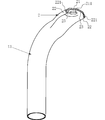
- the present invention is a metal pipe mounting arm separately provided on the upper mold 11 of a chassis frame 1 in which an upper mold 11 and a lower mold 12 formed by pressing a metal plate are joined together.
- (Connecting member) 13 is applied.
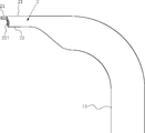
- the mounting arm 13 of this example is a metal pipe connecting member provided on the left and right edges of the upper mold 11 of the chassis frame 1 and protrudes upward, then bends horizontally to the left or right and ends.
- the attachment part 2 is provided in the part.
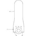
- the mounting portion 2 includes a flat mounting surface 21 at the center of the left and right of the laminated portion in which the end portions are crushed into a substantially gate-shaped cross section and the pipe surfaces are stacked, and the mounting surface It is comprised from the vertical ribs 22 and 22 bent toward the left and right both sides of the laminated part from 21.
- the vertical rib 22 has a teardrop shape in which the folded edge of the laminated portion is inflated, and the pipe surface is not in close contact with each other. Therefore, the vertical rib 22 forms a through hole 221 that communicates the inside and outside of the connection member.
- the through-hole 221 has a teardrop shape in front view following the outer shape of the vertical rib 22, but is slightly elongated because the pipe surface surrounding the opening of the through-hole 221 is cut out.
- the pipe surface surrounding the opening of the through hole 221 is concentric with the bolt hole 211 provided in the mounting surface 21 and is larger than the size of the bolt head passing through the bolt hole 211.
- a pair of left and right oblique end surfaces 23, 23 are formed by cutting symmetrically along the tangent line of the circle Cb.
- the pipe surface is cut symmetrically along the tangent of the virtual circle Cb inclined about 20 degrees from the end face before cutting, and the length Ls of the shortened left and right through holes is determined by the original length of the through hole.
- the length is about half of Lo.
- the present invention can also be configured as follows.
- the pipe surface surrounding the opening of the through hole 221 is concentric with the bolt hole 211 provided in the mounting surface 21 and is larger than the size of the bolt head passing through the bolt hole 211.
- a pair of left and right cut end surfaces 24, 24 are formed by cutting out symmetrically along the circumference of the virtual circle Cb and a line segment intersecting the virtual circle Cb. The cut end face 24 makes it easier to shorten the length of the through hole 221 than to form the oblique end face 23.
- the present invention may be applied only to either the left or right through hole 221.
- the second example is such that the pipe surface surrounding the opening of the through hole 221 is concentric with the bolt hole 211 provided in the mounting surface 21 and is larger than the size of the bolt head passing through the bolt hole 211. Only the right side is cut along the tangent line of the virtual circle Cb, and the oblique end face 23 is formed asymmetrically in the left-right direction. The obliquely end surface 23 may be formed by cutting away only the left side of the pipe surface surrounding the opening of the through hole 221.
- another example 3 is that the pipe surface surrounding the opening of the through hole 221 is concentric with the bolt hole 211 provided in the mounting surface 21 and is passed through the bolt hole 211. Only the right side is cut out along the circumference of the above-mentioned virtual circle Cb and the line segment intersecting the virtual circle Cb, and the cut-out end face 24 is formed asymmetrically in the left-right direction.
- the notch end surface 24 may be formed by asymmetrically cutting the pipe surface surrounding the opening of the through hole 221 only on the left side.
- Chassis frame 11 Upper mold 12 Lower mold 13 Mounting arm (connection member) 2 Mounting part 21 Mounting surface 211 Bolt hole 22 Vertical rib 221 Through hole 23 Diagonal end face 24 Notch end face Lo Original length of through hole Ls Shortened through hole length Cb Virtual circle concentric with bolt hole
Landscapes
- Engineering & Computer Science (AREA)
- Mechanical Engineering (AREA)
- Chemical & Material Sciences (AREA)
- Combustion & Propulsion (AREA)
- Transportation (AREA)
- Body Structure For Vehicles (AREA)
- Securing Of Glass Panes Or The Like (AREA)
- Joining Of Building Structures In Genera (AREA)
Abstract
Description
11 上型
12 下型
13 取付アーム(接続部材)
2 取付部
21 取付面
211 ボルト孔
22 縦リブ
221 貫通孔
23 斜め端面
24 切欠端面
Lo 貫通孔の元の長さ
Ls 短くなった貫通孔の長さ
Cb ボルト孔に同心の仮想円
Claims (2)
- 車体フレームに接続されるパイプからなる接続部材を備えたシャシフレームにおいて、
接続部材は、端部を断面略門型に押し潰して、パイプ面を重ねた積層部の左右中央の平坦な取付面と、前記取付面から積層部の左右両側に向けて折れ曲がった縦リブとから構成される取付部を前記端部に設け、
縦リブは、積層部の折り返し縁を膨らませて、接続部材の内外を連通させる貫通孔を形成し、前記貫通孔の開口を囲むパイプ面を切除して前記貫通孔を短くしたことを特徴とするシャシフレーム。 - 縦リブは、貫通孔の開口を囲むパイプ面を、取付面に設けたボルト孔と同心かつ前記ボルト孔に通すボルトの頭の大きさ以上の仮想円の外側で切除した請求項1記載のシャシフレーム。
Priority Applications (3)
| Application Number | Priority Date | Filing Date | Title |
|---|---|---|---|
| US14/113,643 US8770605B2 (en) | 2011-04-27 | 2012-04-27 | Chassis frame |
| CN201280020269.5A CN103562051B (zh) | 2011-04-27 | 2012-04-27 | 底盘框架 |
| JP2013512468A JP6097685B2 (ja) | 2011-04-27 | 2012-04-27 | シャシフレーム |
Applications Claiming Priority (2)
| Application Number | Priority Date | Filing Date | Title |
|---|---|---|---|
| JP2011099366 | 2011-04-27 | ||
| JP2011-099366 | 2011-04-27 |
Publications (1)
| Publication Number | Publication Date |
|---|---|
| WO2012147921A1 true WO2012147921A1 (ja) | 2012-11-01 |
Family
ID=47072433
Family Applications (1)
| Application Number | Title | Priority Date | Filing Date |
|---|---|---|---|
| PCT/JP2012/061375 Ceased WO2012147921A1 (ja) | 2011-04-27 | 2012-04-27 | シャシフレーム |
Country Status (4)
| Country | Link |
|---|---|
| US (1) | US8770605B2 (ja) |
| JP (1) | JP6097685B2 (ja) |
| CN (1) | CN103562051B (ja) |
| WO (1) | WO2012147921A1 (ja) |
Cited By (2)
| Publication number | Priority date | Publication date | Assignee | Title |
|---|---|---|---|---|
| JP2019135133A (ja) * | 2018-02-05 | 2019-08-15 | 本田技研工業株式会社 | 鞍乗り型車両の車体フレーム補強構造 |
| JP2020104650A (ja) * | 2018-12-27 | 2020-07-09 | 三菱自動車工業株式会社 | 自動車用クロスメンバ |
Families Citing this family (3)
| Publication number | Priority date | Publication date | Assignee | Title |
|---|---|---|---|---|
| JP6137144B2 (ja) * | 2014-11-27 | 2017-05-31 | トヨタ自動車株式会社 | サスペンションメンバ |
| US10676132B2 (en) * | 2016-07-06 | 2020-06-09 | Toyota Jidosha Kabushiki Kaisha | Suspension member |
| CN111137097B (zh) * | 2020-02-14 | 2020-09-25 | 江苏汤臣汽车零部件有限公司 | 平衡悬架组合结构 |
Citations (5)
| Publication number | Priority date | Publication date | Assignee | Title |
|---|---|---|---|---|
| JPS63194049A (ja) * | 1987-01-13 | 1988-08-11 | ハルフェン ゲゼルシャフト ミット ベシュレンクテル ハフツング ウント コンパニー コマンディートゲゼルシャフト | 建物外壁に被覆板を支持するための保持兼支持アンカー |
| JPH0361826U (ja) * | 1989-10-17 | 1991-06-18 | ||
| JPH10324269A (ja) * | 1997-05-23 | 1998-12-08 | Hiruta Kogyo Kk | フロントシャシフレーム |
| JP2004034815A (ja) * | 2002-07-02 | 2004-02-05 | Press Kogyo Co Ltd | サスペンションメンバー |
| JP2008143313A (ja) * | 2006-12-08 | 2008-06-26 | Mitsubishi Steel Mfg Co Ltd | 中空スタビライザ |
Family Cites Families (10)
| Publication number | Priority date | Publication date | Assignee | Title |
|---|---|---|---|---|
| US4138141A (en) * | 1977-02-23 | 1979-02-06 | General Signal Corporation | Force absorbing device and force transmission device |
| JPS6060081A (ja) * | 1983-09-13 | 1985-04-06 | 本田技研工業株式会社 | 鞍乗り型バギ−車 |
| JPH0361826A (ja) | 1989-07-31 | 1991-03-18 | Hitachi Ltd | 温度計測装置及びボイラ燃焼制御装置 |
| JPH09193634A (ja) * | 1996-01-22 | 1997-07-29 | Daihatsu Motor Co Ltd | 自動車用サスペンションアーム |
| JP4007774B2 (ja) * | 2001-06-15 | 2007-11-14 | 本田技研工業株式会社 | 自動車の車体フレーム構造 |
| JP4251832B2 (ja) * | 2002-08-09 | 2009-04-08 | ヒルタ工業株式会社 | シャシフレーム |
| US8496258B2 (en) * | 2003-10-20 | 2013-07-30 | Magna International Inc. | Hybrid component |
| JP4714252B2 (ja) * | 2008-09-25 | 2011-06-29 | 三菱製鋼株式会社 | 中空スタビライザ |
| JP2012025226A (ja) * | 2010-07-21 | 2012-02-09 | Kubota Corp | サスペンション用アーム |
| US8499882B2 (en) * | 2010-12-28 | 2013-08-06 | Kawasaki Jukogyo Kabushiki Kaisha | Utility vehicle |
-
2012
- 2012-04-27 CN CN201280020269.5A patent/CN103562051B/zh active Active
- 2012-04-27 US US14/113,643 patent/US8770605B2/en active Active
- 2012-04-27 JP JP2013512468A patent/JP6097685B2/ja active Active
- 2012-04-27 WO PCT/JP2012/061375 patent/WO2012147921A1/ja not_active Ceased
Patent Citations (5)
| Publication number | Priority date | Publication date | Assignee | Title |
|---|---|---|---|---|
| JPS63194049A (ja) * | 1987-01-13 | 1988-08-11 | ハルフェン ゲゼルシャフト ミット ベシュレンクテル ハフツング ウント コンパニー コマンディートゲゼルシャフト | 建物外壁に被覆板を支持するための保持兼支持アンカー |
| JPH0361826U (ja) * | 1989-10-17 | 1991-06-18 | ||
| JPH10324269A (ja) * | 1997-05-23 | 1998-12-08 | Hiruta Kogyo Kk | フロントシャシフレーム |
| JP2004034815A (ja) * | 2002-07-02 | 2004-02-05 | Press Kogyo Co Ltd | サスペンションメンバー |
| JP2008143313A (ja) * | 2006-12-08 | 2008-06-26 | Mitsubishi Steel Mfg Co Ltd | 中空スタビライザ |
Cited By (3)
| Publication number | Priority date | Publication date | Assignee | Title |
|---|---|---|---|---|
| JP2019135133A (ja) * | 2018-02-05 | 2019-08-15 | 本田技研工業株式会社 | 鞍乗り型車両の車体フレーム補強構造 |
| JP2020104650A (ja) * | 2018-12-27 | 2020-07-09 | 三菱自動車工業株式会社 | 自動車用クロスメンバ |
| JP7164871B2 (ja) | 2018-12-27 | 2022-11-02 | ヒルタ工業株式会社 | 自動車用クロスメンバ |
Also Published As
| Publication number | Publication date |
|---|---|
| US20140049032A1 (en) | 2014-02-20 |
| JPWO2012147921A1 (ja) | 2014-07-28 |
| JP6097685B2 (ja) | 2017-03-15 |
| CN103562051A (zh) | 2014-02-05 |
| US8770605B2 (en) | 2014-07-08 |
| CN103562051B (zh) | 2016-05-25 |
Similar Documents
| Publication | Publication Date | Title |
|---|---|---|
| JP5287927B2 (ja) | 車体構造 | |
| JP6097685B2 (ja) | シャシフレーム | |
| KR101599421B1 (ko) | 차량용 범퍼 | |
| JP6070656B2 (ja) | 車両用衝撃吸収ボックス | |
| CN203558028U (zh) | 用于车辆的前防撞梁及具有其的车辆 | |
| WO2014156065A1 (ja) | バンパ結合構造体及びクラッシュボックス | |
| JP2012232655A (ja) | クロスメンバ | |
| CN102791565A (zh) | 包括刚度得以改善的轮罩的车辆结构 | |
| JPWO2009101981A1 (ja) | バンパー構造 | |
| US20160347368A1 (en) | Sub-frame for vehicle | |
| KR101569825B1 (ko) | 마찰교반용접을 적용한 자동차용 프레임 및 그 제조방법 | |
| JP2014125172A (ja) | 車体前部構造 | |
| JP6624098B2 (ja) | 車両下部構造 | |
| CN104443042B (zh) | 连接板与汽车 | |
| WO2013171828A1 (ja) | トーションビーム式サスペンション | |
| JP5928353B2 (ja) | サスペンションメンバ及びこれを備えた車両前部構造 | |
| JP4938717B2 (ja) | 車体前部構造 | |
| CN204037506U (zh) | 汽车副驾驶位安全气囊的安装支架及相应的汽车 | |
| JP6380844B2 (ja) | 車両前部構造 | |
| JP2023007134A (ja) | 車両後部構造 | |
| CN206012742U (zh) | 汽车前罩锁销加强件总成及汽车前罩板 | |
| CN206220705U (zh) | 螺母板、车门限位器安装结构以及车辆 | |
| CN218949307U (zh) | 一种前顶横梁结构、车身结构及汽车 | |
| JP6247104B2 (ja) | サスペンションフレーム構造 | |
| KR101982872B1 (ko) | 펜더에이프런어퍼멤버와 프런트사이드멤버의 연결구조 |
Legal Events
| Date | Code | Title | Description |
|---|---|---|---|
| 121 | Ep: the epo has been informed by wipo that ep was designated in this application |
Ref document number: 12776912 Country of ref document: EP Kind code of ref document: A1 |
|
| ENP | Entry into the national phase |
Ref document number: 2013512468 Country of ref document: JP Kind code of ref document: A |
|
| WWE | Wipo information: entry into national phase |
Ref document number: 14113643 Country of ref document: US |
|
| NENP | Non-entry into the national phase |
Ref country code: DE |
|
| 122 | Ep: pct application non-entry in european phase |
Ref document number: 12776912 Country of ref document: EP Kind code of ref document: A1 |