WO2012147194A1 - ブラシレスモータ制御装置、およびブラシレスモータ制御方法 - Google Patents
ブラシレスモータ制御装置、およびブラシレスモータ制御方法 Download PDFInfo
- Publication number
- WO2012147194A1 WO2012147194A1 PCT/JP2011/060410 JP2011060410W WO2012147194A1 WO 2012147194 A1 WO2012147194 A1 WO 2012147194A1 JP 2011060410 W JP2011060410 W JP 2011060410W WO 2012147194 A1 WO2012147194 A1 WO 2012147194A1
- Authority
- WO
- WIPO (PCT)
- Prior art keywords
- phase
- zero
- cross point
- brushless motor
- voltage
- Prior art date
Links
Images


Classifications
-
- H—ELECTRICITY
- H02—GENERATION; CONVERSION OR DISTRIBUTION OF ELECTRIC POWER
- H02P—CONTROL OR REGULATION OF ELECTRIC MOTORS, ELECTRIC GENERATORS OR DYNAMO-ELECTRIC CONVERTERS; CONTROLLING TRANSFORMERS, REACTORS OR CHOKE COILS
- H02P6/00—Arrangements for controlling synchronous motors or other dynamo-electric motors using electronic commutation dependent on the rotor position; Electronic commutators therefor
- H02P6/14—Electronic commutators
- H02P6/16—Circuit arrangements for detecting position
- H02P6/18—Circuit arrangements for detecting position without separate position detecting elements
- H02P6/182—Circuit arrangements for detecting position without separate position detecting elements using back-emf in windings
-
- F—MECHANICAL ENGINEERING; LIGHTING; HEATING; WEAPONS; BLASTING
- F02—COMBUSTION ENGINES; HOT-GAS OR COMBUSTION-PRODUCT ENGINE PLANTS
- F02N—STARTING OF COMBUSTION ENGINES; STARTING AIDS FOR SUCH ENGINES, NOT OTHERWISE PROVIDED FOR
- F02N11/00—Starting of engines by means of electric motors
- F02N11/04—Starting of engines by means of electric motors the motors being associated with current generators
-
- H—ELECTRICITY
- H02—GENERATION; CONVERSION OR DISTRIBUTION OF ELECTRIC POWER
- H02P—CONTROL OR REGULATION OF ELECTRIC MOTORS, ELECTRIC GENERATORS OR DYNAMO-ELECTRIC CONVERTERS; CONTROLLING TRANSFORMERS, REACTORS OR CHOKE COILS
- H02P6/00—Arrangements for controlling synchronous motors or other dynamo-electric motors using electronic commutation dependent on the rotor position; Electronic commutators therefor
- H02P6/14—Electronic commutators
- H02P6/16—Circuit arrangements for detecting position
Definitions
- the present invention relates to a brushless motor control apparatus and a brushless motor control method for controlling a three-phase brushless motor used as a starter motor and an AC generator for an internal combustion engine (engine).
- a drive control system for a brushless motor used for a starter of an internal combustion engine (engine) a plurality of hall elements for detecting the position of the rotor (permanent magnet side) in the brushless motor are mounted around the rotor.
- a sensor-type drive control circuit is known (see Non-Patent Document 1).
- this sensor type drive control circuit it is necessary to provide a plurality of Hall elements in the motor, and if necessary, a magnet for detecting the rotor position must be mounted separately from the rotor. This is an obstacle to downsizing and cost reduction.
- the position detection accuracy varies depending on how the Hall elements are attached. Therefore, realization of a sensorless drive control circuit that detects the rotor position without using a sensor such as a Hall element is strongly desired.
- a sensorless type drive control circuit for example, 120 ° energization for detecting the rotor position by detecting the zero cross point of the phase voltage of the non-energized phase (energization is performed for a period of 120 ° out of 180 ° of the total phase period).
- a drive control system based on the system) is known.
- a subcoil Su (for example, refer to the subcoil Su in the three-phase brushless motor 1 in FIG. 1) for detecting any one phase voltage of the three-phase brushless motor is provided, and the one-phase induced in the subcoil Su is provided.
- a brushless motor control device that detects phase voltage (sine wave voltage) and performs 180 ° energization control (see Patent Document 1).
- the brushless motor control device disclosed in Patent Document 1 generates a rectangular wave synchronized with the phase voltage of one phase detected by the subcoil Su, and generates a triangular wave synchronized with the phase of 0 ° to 180 ° of the rectangular wave. To do. Further, a triangular wave synchronized with the phase of the rectangular wave from 180 ° to 360 ° is generated. Then, based on these triangular waves, a rectangular wave (rotor position detection waveform) synchronized with the other two phases is generated, the rotor position is estimated by these rectangular waves, and the three-phase brushless motor is energized by 180 °. Drive control is performed.
- phase of one phase induced in the sub-coil Su of the three-phase brushless motor (brushless motor operating as a three-phase AC generator)
- the phase of the other two-phase phase voltages can be determined.
- the rotation speed of the three-phase brushless motor that is, the frequency of the U-phase voltage (AC voltage) Vsu output from the subcoil Su does not change abruptly, so the waveform of the previous cycle is almost the same as the waveform of the current cycle.
- the waveform of the previous cycle is almost the same as the waveform of the current cycle.
- the half period T2 of the waveform 2 is almost the same as the half period T1 of the waveform 1 one cycle before.
- Step 1 As shown in FIG. 10A, in the cycle of waveform 1, a rectangular wave Ru is generated from the AC voltage Vsu output by the subcoil Su.
- the half cycle of the rectangular wave Ru corresponding to the waveform 1 coincides with the half cycle T1 of the AC voltage Vsu in the cycle of the waveform 1.
- Step 2 Subsequently, the time of the half cycle T1 of the rectangular wave Ru is counted.
- the resolution n is an amount that defines the smoothness of the slope of the triangular wave voltage VB.
- Step 5 Subsequently, as shown in FIG. 10B, the triangular wave voltage VB is increased by the voltage v1 at the rising timing of the waveform 2 of the next cycle (timing to start counting T2). Maintain only for time t1.
- Step 6 In the same waveform 2 cycle, the triangular wave voltage VB is further increased by the voltage v1 at the timing when the time t1 has elapsed, and when this is repeated n times in total, a stepped waveform as shown in FIG. 10B is obtained. And a step-like waveform corresponding to the slope portion of the triangular wave voltage corresponding to the cycle of waveform 2 is obtained. If the value of the resolution n is increased, the stepped waveform becomes smooth and a better triangular wave can be obtained.
- a triangular wave having a constant peak voltage Vp which is a triangular wave voltage corresponding to each cycle of the AC voltage Vsu, can be generated using the waveform of the AC voltage Vsu one cycle before.
- the first triangular wave S1 is generated in synchronization with the phase of the U-phase rectangular wave Ru from 0 ° to 180 °, and the first triangular wave S1 is synchronized with the phase of 180 ° to 360 °.
- Two triangular waves S2 are generated.
- a voltage detection circuit (comparison circuit) (not shown) inverts the level at a voltage point X2 that is 2/3 of the peak voltage Vp of the first triangular wave S1, and 2/3 of the peak voltage Vp of the second triangular wave S2.
- a V-phase rectangular wave Rv whose level is inverted at the voltage point Y2 is generated, the level is inverted at the voltage point X1 that is 1/3 of the peak voltage Vp of the first triangular wave S1, and the peak voltage Vp of the second triangular wave S2 is 1
- a W-phase rectangular wave Rw whose level is inverted at a voltage point Y1 of / 3 is generated.
- the rectangular waves Rv and Rw synchronized with the other two phases can be generated with reference to the rectangular wave Ru synchronized with the U-phase AC output voltage Vsu.
- the brushless motor control device estimates the rotor position from these rectangular waves Ru, Rv, and Rw, and performs 180 ° energization control on the brushless motor.
- the motor drive device described in Patent Document 3 is intended to provide a motor drive device and a rotor position detection method capable of accurately detecting rotor position information used for motor drive without using a rotation position sensor. .
- the brushless motor control device described in Patent Document 1 described above requires a triangular wave generation circuit for generating a triangular wave and a voltage detection circuit for detecting the voltage of the triangular wave. For this reason, the cost increase by providing the triangular wave generation circuit and the voltage detection circuit occurs. In addition, there is a problem that detection accuracy deteriorates due to variations in the characteristics of components used in the voltage detection circuit. This situation also applies to the battery charger described in Patent Document 2.
- the brushless motor control device is a brushless motor control device that drives and controls a three-phase brushless motor, and a phase voltage detection unit that detects any one phase voltage of the three-phase brushless motor;
- a zero-cross point detection circuit that detects a zero-cross point of the phase voltage of one phase detected by the phase voltage detection unit, and an interval time T between the zero-cross points detected by the zero-cross point detection circuit, Based on the interval time T, a zero cross point estimator that calculates the time T / 3 and 2T / 3 and estimates the zero cross point of the other two phases, and the zero cross point of the phase voltage of the one phase and the estimated other
- An energization control unit that estimates the rotational position of the rotor based on the two-phase zero-crossing point and controls energization of each phase winding of the three-phase brushless motor.
- the phase voltage of any one of the three-phase brushless motors is detected, the interval time T between the zero cross points is measured, and T / The time of 3 and 2T / 3 is calculated, and the zero cross point of the other two phases is estimated. Based on the estimated zero-cross point, the phase of the other two-phase voltages (and the rotor position based on the phase voltage of each phase) is estimated to control the energization of each phase winding. .
- the triangular wave generation circuit and the voltage detection circuit are not used based on the phase voltage of only one phase of the three-phase brushless motor.
- the phase of the other two phase voltages (and the rotor position based on the phase voltage phase of each phase) can be estimated. For this reason, it is possible to estimate the rotor position based on the phase voltage of only one phase of the three-phase brushless motor and to control the energization to each phase winding of the three-phase brushless motor.
- the zero-cross point estimation unit is configured such that the zero-cross point is generated before the zero-cross point interval time T elapses after the zero-cross point is generated in the one-phase phase voltage.
- the next zero-cross point occurs in the phase voltage of
- the other two-phase zero-cross points are re-estimated based on the next zero-cross point.
- the phase voltage of any one of the three-phase brushless motors is detected, the interval time T between the zero cross points is measured, and T / The time of 3 and 2T / 3 is calculated, and the zero cross point of the other two phases is estimated.
- the other two-phase zero-cross points are re-estimated.
- the other two-phase phases are changed based on the phase voltage of only one phase of the three-phase brushless motor according to the fluctuation of the motor rotation speed.
- the phase of the voltage can be estimated.
- the zero cross point estimation unit is configured such that the next zero cross point is generated in the phase voltage of the one phase before the estimated other two phase zero cross points. Based on the next zero-cross point, the other two-phase zero-cross points are re-estimated.
- the phase voltage of any one of the three-phase brushless motors is detected, the interval time T between the zero cross points is measured, and T / The time of 3 and 2T / 3 is calculated, and the zero cross point of the other two phases is estimated.
- next zero-cross point occurs in the one-phase phase voltage before the estimated other two-phase zero-cross point
- the other two-phase zero-cross points are again determined based on the next zero-cross point.
- the other two phases are changed based on the phase voltage of only one phase of the three-phase brushless motor according to the fluctuation of the motor rotation speed.
- the phase of the phase voltage can be estimated.
- the energization control unit when the energization control unit operates as a three-phase AC generator that charges the battery, the zero-cross point of the phase voltage of the one phase. And the estimated other two-phase zero-cross points, the phase of the other two-phase phase voltage is estimated, and the AC output voltage of each phase output from the three-phase brushless motor is rectified and phased.
- a phase control regulator unit that controls and charges the battery is provided.
- the zero-cross point estimation unit calculates the phase voltage of the one phase.
- the phase control regulator unit in the energization control unit includes the one-phase phase voltage zero-cross point and the estimated other two-phase zero-cross point. Based on this, the phase of the other two-phase phase voltage is estimated, the AC output voltage of each phase output from the three-phase brushless motor (three-phase AC generator) is rectified and phase controlled, and the battery is charged. .
- the three-phase brushless motor operates as a three-phase AC generator, based on the phase voltage of only one phase of the three-phase brushless motor, without using the triangular wave generation circuit and the voltage detection circuit, The phase of the two-phase phase voltage is estimated, and the battery can be charged by rectifying and phase controlling the AC output voltage of each phase output from the three-phase brushless motor (three-phase AC generator).
- the three-phase brushless motor is configured such that each of the U, V, and W phase coils on the stator side includes a plurality of poles, and the U, V, and W A phase voltage of one phase of the three-phase brushless motor is detected by a coil in which one pole of one of the phases is in a floating state.
- a three-phase brushless motor having a plurality of poles on the stator side is used, and a one-pole coil in any one of the phases is floated to form a subcoil.
- the phase time of the phase is detected, and at the same time, the interval time T between the zero cross points is measured, and the time of T / 3 and 2T / 3 is calculated to estimate the zero cross points of the other two phases To do.
- the decrease in the output of the three-phase brushless motor can be suppressed to one pole of one phase, and the subcoil can be formed without increasing the cost of the product.
- the three-phase brushless motor operates as a starter motor for starting the internal combustion engine and operates as a three-phase AC generator that is rotationally driven by the internal combustion engine. It is a motor.
- the three-phase brushless motor operates as a starter motor when the internal combustion engine is started, and is rotated by the internal combustion engine after the internal combustion engine is started.
- a rotational position sensorless three-phase brushless motor is operated as a starter motor and when it is operated as a three-phase AC generator, a triangular wave is generated based on the phase voltage of only one phase of the three-phase brushless motor. Without using the circuit and the voltage detection circuit, the phase of the other two-phase phase voltage (and the rotor position based on the phase voltage of each phase) can be estimated.
- the brushless motor control method is a brushless motor control method for driving and controlling a three-phase brushless motor, and a phase voltage detection procedure for detecting any one phase voltage of the three-phase brushless motor.
- a zero-cross point detection procedure for detecting a zero-cross point of the phase voltage of one phase detected by the phase voltage detection procedure, and an interval time T between the zero-cross points detected by the zero-cross point detection procedure. Based on the interval time T between the points, the time of T / 3 and 2T / 3 is calculated to estimate the zero cross point of the other two phases, and the zero cross point of the phase voltage of the one phase is estimated.
- Energization control for estimating the rotational position of the rotor based on the other two-phase zero-cross points and controlling the energization of each phase winding of the three-phase brushless motor Including a forward, a.
- the phase voltage of any one phase of the three-phase brushless motor is detected, the interval time T between the zero cross points is measured, and the interval time T between the zero cross points is measured. / 3 and 2T / 3 times are calculated and the other two-phase zero-cross points are estimated.
- the phase of the other two-phase voltages (and the rotor position based on the phase voltage of each phase) is estimated to control the energization of each phase winding.
- the triangular wave generation circuit and the voltage detection circuit are not used based on the phase voltage of only one phase of the three-phase brushless motor.
- the phase of the other two phase voltages (and the rotor position based on the phase voltage phase of each phase) can be estimated. For this reason, it is possible to estimate the rotor position based on the phase voltage of only one phase of the three-phase brushless motor and to control the energization to each phase winding of the three-phase brushless motor.
- the phase voltage of any one phase of the three-phase brushless motor is detected, the interval time T between the zero cross points is measured, and on the basis of the interval time T between the zero cross points, T / 3 and 2T / 3 times are calculated and the other two-phase zero-cross points are estimated. Based on the estimated zero-cross point, the phase of the other two-phase voltages (and the rotor position based on the phase voltage of each phase) is estimated to control the energization of each phase winding. .
- FIG. 3A It is a figure which shows the structure of the brushless motor control apparatus concerning embodiment of this invention. It is a figure which shows the example of 1 structure of a subcoil. It is a figure which shows the other structural example of a subcoil. It is a figure for demonstrating operation
- FIG. 1 is a diagram showing a configuration of a brushless motor control apparatus according to an embodiment of the present invention.
- a brushless motor control device 10 shown in FIG. 1 is a control device that drives a three-phase brushless motor 1 by using a battery 4 as a DC power source and converting a DC voltage of the battery 4 into an AC voltage.
- a three-phase brushless motor (hereinafter also simply referred to as “motor”) 1 is a motor for a starter of the engine 5 and also a three-phase AC generator that is rotationally driven by the engine 5.
- the three-phase brushless motor 1 includes a stator 2 having U, V, and W phase coils (coils wound around an iron core) and a neutral wire N of the coils, and a four-pole permanent magnet (two pairs of N , S pole).
- Three-phase (U, V, W) windings (coils) are wound around the stator 2 in order in the circumferential direction.
- the U-phase coil of the stator 2 is provided with a sub-coil (Su) 2a in parallel.
- the sub-coil Su induces a voltage induced in the U-phase (more precisely, induced in the sub-coil Su by the permanent magnet of the rotor 3). Sine wave AC voltage) Vsu.
- the subcoil Su may be provided in another phase (V phase or W phase).
- a three-phase bridge circuit including switching elements Q1 to Q6 of an Nch type FET (Field Effect Transistor) is provided.
- the drain terminals of the switching elements Q1 to Q3 on the upper arm side are commonly connected to the + side terminal of the battery 4 serving as a DC power source.
- the source terminals of the switching elements Q4 to Q6 on the lower arm side are commonly connected to the negative terminal of the battery 4 serving as a DC power source.
- the source terminal of the switching element Q1 on the upper arm side and the drain terminal of the switching element Q4 on the lower arm side are connected, and the connection point between the switching elements Q1 and Q4 is the U-phase coil terminal of the three-phase brushless motor 1 It is connected to the.
- the source terminal of the switching element Q2 on the upper arm side and the drain terminal of the switching element Q5 on the lower arm side are connected, and the connection point of the switching elements Q2 and Q5 is the V-phase coil terminal of the three-phase brushless motor 1 It is connected to the.
- the source terminal of the switching element Q3 on the upper arm side and the drain terminal of the switching element Q6 on the lower arm side are connected, and the connection point between the switching elements Q3 and Q6 is the W-phase coil terminal of the three-phase brushless motor 1 It is connected to the.
- a flywheel diode Dx is connected in parallel to each of the switching elements Q1 to Q6 so that the cathode is in the positive terminal direction of the battery 4 and the anode is in the negative terminal direction of the battery 4 as shown in the figure.
- the switching elements Q1 to Q6 may be IGBTs (Insulated Gate Bipolar Transistors) or bipolar transistors.
- the brushless motor control apparatus 10 includes a Hi (high) pre-driver circuit 11 that drives the upper arm side switching elements (FETs) Q1 to Q3 on / off, and a lower arm side switching element (FET).
- FET) Q4 to Q6 have a Lo (low) side pre-driver circuit 12, a zero-cross point detection circuit 13, and a control unit 20.
- the switching elements Q1 to Q6 are driven by gate drive signals output from the Hi-side predriver circuit 11 and the Lo-side predriver circuit 12. This gate drive signal is generated in the pre-driver circuits 11 and 12 based on the FET drive signal output from the control unit (control unit configured by a CPU or the like) 20.
- the zero-cross point detection circuit 13 is provided for each phase coil (U-phase coil, V-phase coil, W-phase coil). ) To detect the zero cross points of the voltages Vu, Vv, Vw induced.
- the zero-cross point detection circuit is induced in the subcoil Su attached to the U-phase coil of the three-phase brushless motor 1 when the three-phase brushless motor 1 is rotating at high speed (when 180 ° energization described later is performed).
- the zero cross point is detected from the applied voltage (U-phase voltage) Vsu.
- the zero cross point generated in the AC voltage induced in each phase coil (U-phase coil, V-phase coil, W-phase coil) at 120 ° energization and the zero cross point generated in the AC voltage induced in the subcoil Su are: This occurs when the midpoint (boundary point between N and S poles) of the magnetic pole of the rotor 3 coincides with the position of the coil.
- the control unit 20 includes a zero cross point estimation unit 21 and an energization control unit 22.
- the energization control unit 22 includes a 120 ° energization control unit 23 that energizes the three-phase brushless motor 1 by 120 ° and a 180 ° energization control unit 24 that energizes the three-phase brushless motor 1 by 180 °. Have.
- the 120 ° energization control unit 22 controls the three-phase brushless motor 1 to be driven by 120 ° energization (energization of two phases among the three phases).
- the 180 ° energization control unit 22 controls the three-phase brushless motor 1 to be driven by 180 ° energization (all-phase energization) when the three-phase brushless motor 1 rotates at a high speed.
- the zero cross point estimation unit 21 in the control unit 20 receives information on the zero cross point of the voltage Vsu induced in the subcoil Su from the zero cross point detection circuit 13 when energizing the three-phase brushless motor 1 by 180 °. . Then, the zero cross point estimation unit 21 measures an interval time T between zero cross points (adjacent zero cross points) of the voltage Vsu induced in the subcoil Su. For example, the interval time T between the zero cross points is measured by counting the time from when the zero cross point occurs in the output voltage Vsu of the subcoil Su until the next time the zero cross point occurs in the output voltage Vsu by a timer or the like. .
- the zero cross point estimation unit 21 calculates the time of “T / 3” and “2T / 3” based on the interval time T between the zero cross points, and zero cross points of the other two phases (V phase and W phase). (Phase) is estimated. Then, the zero-cross point estimation unit 21 obtains information on the zero-cross point (U-phase zero-cross point) of the voltage Vsu induced in the subcoil Su and information on the estimated zero-cross points of the other two phases (V and W phases). To the energization control unit 22. The details of the other two-phase (V-phase, W-phase) zero-cross point estimation operations in the zero-cross point estimation unit 21 will be described later.
- the subcoil Su may be provided in either the V phase or the W phase instead of the U phase.
- the zero-cross point estimation unit 21 estimates another two-phase zero-cross point where the sub-coil Su is not provided, based on the voltage Vsu induced in the sub-coil Su.
- a microcomputer (or a microcontroller) is mounted in the brushless motor control device 10, and the control unit 20, the zero cross point estimation unit 21, the energization control unit 22, and other components in the brushless motor control device 10 are provided.
- a circuit that can realize its processing function by executing a software program may be realized by software processing. Of course, it may be configured by hardware.
- the sub-coil Su provided in the three-phase brushless motor 1 is provided with a sub-coil Su in parallel to the U-phase coil of the stator, and this sub-coil Su induces a U-phase induced voltage (induced to the sub-coil Su by rotor rotation).
- the subcoil Su can also be configured by the method shown in FIG.
- a three-phase brushless motor having a plurality of poles (six poles in the example in the figure) on the stator side is used, and the one-pole coil 6 in any one of the phases (U phase in the example in the figure) is used.
- the subcoil Su is formed by floating. That is, one of the six U-phase coils 6 is removed (floating), and the terminals SUB1 and SUB2 are pulled out from the removed coil 6, and the U-phase voltage is applied to the terminals SUB1 and SUB2. (AC voltage induced in the coil 6 by the rotor 3) Vsu is obtained.
- the zero cross point estimation unit 21 receives information on the zero cross point of the voltage Vsu induced in the floating coil 6 from the zero cross detection circuit 13. Then, the zero cross point estimation unit 21 detects the phase of the voltage Vsu induced in the subcoil Su, and at the same time, measures the time T between adjacent zero cross points, and zero cross points of the other two phases (V and W phases). Is estimated.
- FIG. 3A shows an example in which the one-pole coil 6 of the U-phase coil is separated from the other windings to be in a floating state, and the coil 6 in this floating state is used as a subcoil Su. It is the same figure as the figure shown.
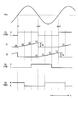
- FIG. 3B shows the time t in the horizontal direction, the voltage (U phase voltage) Vsu induced in the subcoil Su, the zero cross point of this voltage Vsu, and the estimated zero cross points of the V and W phase voltages. And V and W phase waveforms (virtual V and W phase induced voltage waveforms that are not actually detected) having this estimated zero-cross point.
- the zero-cross point estimation unit 21 divides this interval time T into three (divided at a phase of 60 °) based on the interval time T (phase of 180 °) between the adjacent zero-cross points a1 and a2.
- the time of 1 / 3T and 2 / 3T is calculated.
- the time “1 / 3T” calculated by the zero cross point estimator 21 is the time when the zero-cross point b1 of the W-phase voltage is generated from the time t1 when the zero-cross point a2 of the V-phase is generated. This corresponds to the time until t2.
- the time “2 / 3T” calculated by the zero cross point estimation unit 21 is the time from time t1 when the V phase zero cross point a2 occurs to time t3 when the V phase zero cross point c1 occurs. Equivalent to.
- the zero-cross point estimation unit 21 can estimate the W-phase and V-phase zero-cross points to be generated next based on the interval time T between adjacent zero-cross points of the output voltage Vsu of the subcoil Su. This zero cross point is generated when the position of each phase coil coincides with the midpoint of the rotor magnetic pole (boundary point between N and S poles), and the rotor position can be estimated by estimating this zero cross point. become.
- the energization control unit 22 can energize each phase winding of the three-phase brushless motor 1 by selecting an energization pattern and energization timing according to the rotor position.
- the zero-cross point estimation unit 21 measures the interval time T ′ between the adjacent zero-cross points a2 and a3. Based on the interval time T ′, the times “1 / 3T ′” and “2 / 3T ′” are calculated again.
- the time “1 / 3T ′” calculated by the zero cross point estimation unit 21 corresponds to the time when the W phase zero cross point b2 occurs at time t5, as shown in FIG. 3B.
- the time “2 / 3T ′” calculated by the zero cross point estimation unit 21 corresponds to the time at which the V-phase zero cross point c2 occurs at time t6.
- the zero cross point estimating unit 21 repeats the measurement of the interval time T between the zero cross points of the output voltage of the subcoil Su and the estimation process of the W and V phase zero cross points by calculating the times of 1 / 3T and 2 / 3T.
- the brushless motor control device 10 performs positive and negative operations between the two-phase coils of the U, V, and W phase coils by, for example, the method described in Patent Document 1 described above.
- the rotor stop position can be detected from the rising characteristics of the current.
- the energization control unit 22 starts the motor by selecting the energization phase of the motor winding that can generate the maximum torque at the rotor stop position.
- the energization control unit 22 detects the zero cross point of the voltage Vsu induced in the subcoil Su and the zero cross point of the W and V phases estimated by the zero cross point estimation unit 21. Based on the above, energization to each phase winding of the three-phase brushless motor 1 is controlled. The control of the three-phase brushless motor 1 based on the zero cross point estimation is performed by the 180 ° energization control unit 22 in the energization control unit 22. When the three-phase brushless motor 1 is driven at a low speed, 120 ° energization can be performed instead of 180 ° energization. This 120 ° energization will be described later.
- FIG. 4 is a diagram for explaining the control operation of the three-phase brushless motor based on the zero cross point estimation.
- FIG. 4 takes time t in the horizontal direction, and has the output voltage Vsu of the subcoil Su, the zero cross point of the voltage Vsu, the estimated zero cross point of the V and W phases, and the estimated zero cross point. It is the figure which showed V, W phase waveform (virtual V, W phase induced voltage waveform which is not actually detected).
- FIG. 4 shows a waveform (rotor) in which a rectangular wave Ru synchronized with the U phase generated based on the zero cross point, a rectangular wave Rw synchronized with the W phase, and a rectangular wave Rv synchronized with the V phase are arranged side by side. (Position detection waveform).
- the rectangular wave Ru is a waveform whose level is inverted at each zero-cross point (for example, a2, a3, a4) of the U-phase voltage waveform (more precisely, the output voltage waveform of the subcoil Su). .
- the rectangular wave Ru changes from the H level (high level) to the L level (low level) at the zero cross point a2, changes from the L level to the H level at the zero cross point a3, and from the H level at the zero cross point a4. Changes to L level.
- the W-phase rectangular wave Rw is a waveform whose level is inverted at each zero-cross point (for example, b1, b2, b3) of the W-phase voltage waveform (virtual voltage waveform that is not actually detected).
- the W-phase rectangular wave Rw changes from the L level to the H level at the zero cross point b1, changes from the H level to the L level at the zero cross point b2, and changes from the L level to the H level at the zero cross point b3.
- the V-phase rectangular wave Rv is a waveform whose level is inverted at each zero-cross point (for example, c1, c2, c3) of the V-phase voltage waveform (virtual voltage waveform that is not actually detected).
- the V-phase rectangular wave Rv changes from the H level to the L level at the zero cross point c1, changes from the L level to the H level at the zero cross point c2, and changes from the H level to the L level at the zero cross point c3. .
- each rectangular waveform Ru shown in FIG. 4 synchronized with the W, U, and V phases.
- Rv, and Rw can be detected at the H level and L level to detect rotor position information by zero-cross point detection. For example, as shown in FIG. 4, it is possible to detect 6 sections from 0 to 5 every 60 degrees. For example, in one rotation cycle from time t1 to time t7 (U phase 360 ° period), the 0th stage ST0 from time t1 to t2, the first stage ST1 from time t2 to t3, and the second stage from time t3 to t4.
- stage ST2 The rotor position is detected every 60 ° by six sections: stage ST2, third stage ST3 from time t4 to t5, fourth stage ST4 from time t5 to t6, and fifth stage ST5 from time t6 to t7.
- the switching point of the stage (the stage of the phase voltage every 60 degrees applied to the U, V, and W phase coils) can be used.
- the brushless motor control device 10 detects the zero cross point of the voltage Vsu induced only in one subcoil Su, and based on the zero cross point of the voltage Vsu, the zero cross point of the other two phases (V and W phases). Is estimated (rotor position is estimated). Then, the energization control unit 22 switches the stage based on the zero-cross point of the output voltage (U-phase voltage) Vsu of the subcoil Su and the estimated zero-cross point of the other two phases (V and W phases). Thus, switching of energized phases and energization timing for the U, V, and W phase coils can be controlled.
- the zero cross point is estimated by the zero cross point estimation unit 21, thereby selecting the energization pattern and the energization timing according to the rotor position and energizing the motor windings. it can.
- the voltage (U-phase voltage) Vsu induced in the subcoil Su is detected and the zero cross point is estimated.
- the 180-degree energization is performed, but when the motor is rotating at a low rotation, the motor may be driven by the 120-degree energization method.
- the 120 ° energization method itself is a well-known general method, and the 120 ° energization will be briefly described below.
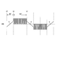
- FIG. 5 is a diagram for explaining 120 ° energization. This 120 ° energization is performed by a 120 ° energization control unit 23 in the energization control unit 22.
- the coil is energized only during the period of 120 degrees during the entire period of 180 degrees. Therefore, a non-energized phase is generated in each of the U, V, and W phases, and the rotor position can be detected by detecting the zero cross points a, b, and c of the non-energized phase.
- the U-phase coil becomes a non-energized phase from time t0 to t1 (between phases 60 °) and becomes a conducting phase from time t1 to t2 (between phases 120 °).
- an induced voltage is generated by the rotor magnetic pole in the U-phase coil, and the rotor position is detected by detecting the zero cross point a. be able to.
- the rotor position can be detected by detecting the zero-cross point b in the section where the non-energized phase is set.
- the rotor position can be detected by detecting the zero-cross point c in the section where the non-energized phase is set.
- the rotor position (rotor magnetic pole switching point) can be detected every 60 °, and the energization phase and energization timing for the U, V, and W phase coils are determined according to the rotor position, and the three-phase brushless The motor 1 can be driven.
- the zero cross point detection by the voltage (U phase voltage) Vsu induced in the sub-coil Su and the other two phases by the zero cross point estimation unit 21 (instead of the 120-degree energization)
- the three-phase brushless motor 1 can be controlled by 180 ° energization.
- the ON / OFF duty ratio can be controlled during the ON period of each of the switching elements Q1 to Q6.
- the on / off duty ratio can be changed.
- the voltage applied to the motor winding can be changed according to the rotation speed of the three-phase brushless motor 1.
- the voltage applied to the motor winding can be changed by controlling the on / off duty ratio in the same manner.
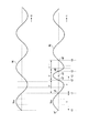
- FIG. 7 is a diagram showing an example in which the rotation speed of the three-phase brushless motor varies.
- the waveforms (W2) of the voltage Vsu induced in the subcoil Su are shown side by side.
- the motor rotation speed fluctuates, and the position of the originally expected zero cross point a3 (position at time t2) at time t2 ′. If the next zero cross point a3 ′ occurs in the output voltage Vsu of the subcoil Su earlier than the other, the other two-phase zero cross points are estimated again based on the next zero cross point a3 ′.
- the zero-cross point estimation unit 21 determines the interval between the zero-cross points a1 and a2 based on the zero-cross point a1 at the time t0 and the zero-cross point a2 at the time t1 of the output voltage Vsu of the subcoil Su.
- Calculate the time of “T / 3” and “2T / 3” when the interval time T between the adjacent zero cross points is divided into three (divided at 60 ° phase), and the other two phases (V, W phase) Estimate the zero-cross point of.
- the zero cross point estimation unit 21 updates the interval time T of the zero cross points. That is, the zero cross point estimation unit 21 at this time (time t2 ′), based on the zero cross point a3 ′ at the time t2 ′ and the zero cross point a2 at the time t1, is the interval time T ′ (t2 ′) of the zero cross points. -T1) is calculated again and updated.
- the zero-cross point estimation unit 21 calculates “T ′ / 3” and “2T ′ / 3” based on the updated interval time T ′ of the zero-cross points, and calculates the other two phases (V, W phase). ) Re-estimate the zero-crossing point. Then, the energization control unit 22 controls energization to the three-phase brushless motor 1 based on the information of the other two-phase (V, W phase) zero-cross points re-estimated by the zero-cross point estimation unit 21.
- the energization control unit 22 controls energization to the three-phase brushless motor 1 based on the information of the other two-phase (V, W phase) zero-cross points re-estimated by the zero-cross point estimation unit 21.
- the zero cross point estimation unit 21 performs zero crossing based on the zero cross point a5 at time t4 and the zero cross point a4 at time t3.
- the energization control unit 22 controls energization to the three-phase brushless motor 1 based on the information of the other two-phase (V, W phase) zero-cross points re-estimated by the zero-cross point estimation unit 21.
- the motor rotation speed fluctuates, and the zero cross point occurs earlier in the voltage (U-phase voltage) Vsu induced in the subcoil Su than the originally expected time of the zero cross point.
- the interval time T between the zero cross points is updated based on the zero cross point detected at that time and the previously detected zero cross point.
- the zero cross point estimation unit 21 calculates “T / 3” and “2T / 3” based on the updated interval time T of the zero cross points, and zero crosses of the other two phases (W and V phases). Reestimate the points.
- the energization control unit 22 controls energization to the three-phase brushless motor 1 based on the re-estimated zero cross point of the other two phases (W and V phases). Thereby, even when the motor rotation speed fluctuates, it is possible to appropriately control the energization of the three-phase brushless motor 1.
- the zero cross point a3 ′ is reached at the time t2 ′ earlier than the time t2 of the originally expected zero cross point a3.
- the next zero cross point is generated in the voltage Vsu induced in the subcoil Su before, for example, “2T / 3” time elapses before the other two-phase zero cross points estimated by the zero cross point estimation unit 21.
- the other two-phase zero-cross points can be estimated again based on the next zero-cross point.
- the three-phase brushless motor 1 is driven as a motor (for example, when driven as a starter motor) has been described above.
- the three-phase brushless motor 1 is rotationally driven by the engine 5 and three-phase AC power generation is performed.
- An example in the case of operating as a machine will be described. (Description of the case where the three-phase brushless motor 1 operates as a three-phase AC generator)
- the three-phase brushless motor 1 becomes a three-phase AC generator.
- the brushless motor control device converts (forward-converts) the three-phase AC output voltage output from the three-phase brushless motor 1 into a DC voltage. It operates so that the charging current flows through the battery 4 by the voltage.
- the brushless motor control device performs advance / retard control for controlling the power generation amount of the three-phase brushless motor 1 in order to charge the battery 4 efficiently. Since the advance / retard angle control method itself is not directly related to the present invention, the advance / retard angle control will be briefly described below (see Patent Document 2 for details). reference).
- the advance angle / retard angle control is performed by setting the energization timing of the switching elements Q1 to Q6 constituting the rectifier in the brushless motor control device with respect to the phase of the AC output voltage of the three-phase brushless motor 1.
- the power generation amount of the three-phase brushless motor 1 is controlled by moving to the advance side or the retard side.
- this advance / retard control when the voltage of the battery 4 is lower than the reference voltage and needs to be charged, the brushless motor control device is retarded to enter the battery charge state, and the voltage of the battery 4 is set to the reference voltage. If charging is not required higher than that, the brushless motor control device can be advanced so that energy is discharged from the battery to the three-phase brushless motor 1.
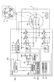
- FIG. 9 is a diagram illustrating a configuration example when the brushless motor control device is operated as a battery charging device, and is a configuration example when the brushless motor control device 10a operates as a battery charging device and a motor driving device.
- the brushless motor control device 10a shown in FIG. 9 includes a phase control regulator unit 25 (an advance / retard angle control unit 25a) in the energization control unit 22a. ) Is added.
- a resistance voltage dividing circuit (a circuit constituted by resistors R1 and R2) for detecting the battery voltage Vbat in the control unit 20a, a reference voltage circuit 31 for generating the reference voltage Vref, the battery voltage Vbat and the reference voltage
- an error amplifier (amplifier) 32 for comparing Vref is newly added.
- Other configurations are the same as those of the brushless motor control apparatus 10 shown in FIG. For this reason, the same code
- the error amplifier 32 compares the feedback signal Vfb from the actual battery voltage Vbat and the set value (target value) Vref of the battery charging voltage, amplifies the difference signal, and outputs it as an error amplifier output Vc.
- the error amplifier output Vc is “Vc> 0” when the battery voltage Vbat is low and “Vfb ⁇ Vref”, and “Vc ⁇ 0” when the battery voltage Vbat is high and “Vfb> Vref”. It becomes.
- Vc> 0 the battery 4 is charged (retard angle control), and when “Vc ⁇ 0”, the battery 4 is discharged (advance angle control).
- the advance / retard angle control unit 25a in the phase control regulator unit 25 receives a signal of the error amplifier output Vc from the error amplifier output Vc, determines an advance angle / retard angle amount, and according to the advance angle / retard angle amount. On / off signals of the switching elements Q1 to Q6 are generated and output to the Hi-side predriver circuit 11 and the Lo-side predriver circuit 12.
- the zero-cross point detection circuit 13 detects the zero-cross point of the output voltage Vsu of any one phase of the three-phase AC generator, for example, the U-phase sub-coil Su described above. . Then, the zero cross point estimator 21 estimates the other two-phase (V, W phase) zero cross points. Then, a three-phase brushless motor includes a zero-cross point of the voltage (U-phase voltage) Vsu induced in the subcoil Su and the other two-phase (V-phase and W-phase) zero-cross points estimated by the zero-cross point estimation unit 21. The phase of the AC output voltage of each phase of 1 is estimated.
- the phase control regulator unit 25 determines the advance / retard amount based on the output voltage Vc of the error amplifier 32 with respect to the estimated phase of the AC output voltage of the three-phase brushless motor 1, and
- the advance / retard angle control unit 25a controls the energization timing of the switching elements Q1 to Q6 to the advance side or the retard side.
- the brushless motor control device 10a does not include a rotor position detection sensor in each phase of the three-phase brushless motor (three-phase AC generator) 1, and the above-described triangular wave generation circuit or Without providing a voltage detection circuit, advance / retard control can be performed on the AC output voltage of the three-phase brushless motor 1 to control charging of the battery 4.
- a sub-coil for detecting an AC output voltage
- any one of the three-phase AC generators including the U, V, and W phases.
- Auxiliary winding is provided, and the zero-cross point of the AC output voltage of the one-phase sub-coil is detected to estimate the other two-phase zero-cross point (phase).
- the three-phase brushless motor 1 can be controlled without providing the above-described triangular wave generation circuit and voltage detection circuit. For this reason, the configuration of the brushless motor control devices 10 and 10a can be simplified, and the cost can be reduced.
- the embodiment of the present invention can be applied to a control device for a three-phase brushless motor and a control method for a three-phase brushless motor.
- this brushless motor control device and brushless motor control method when a three-phase brushless motor without a rotational position sensor is controlled by 180 ° energization, the phase voltage of only one phase of the three-phase brushless motor is detected, When estimating the phase of the other two-phase phase voltages from this one-phase phase voltage, the phases of the other two-phase phase voltages can be estimated without using the triangular wave generation circuit and the voltage detection circuit.
Abstract
Description
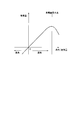
(工程2) 続いて、矩形波Ruの半周期T1の時間をカウントする。
(工程3) 続いて、半周期T1の時間のカウント数を所定の分解能nで除算して、時間t1(=T1/n)を得る。ここで、分解能nは、三角波電圧VBのスロープの滑らかさを規定する量であり、分解能nが高い程、三角波電圧VBのスロープが滑らかになる。
(工程4) 続いて、三角波電圧VBのピーク電圧Vpを所定の分解能nで除算して、電圧v1(=Vp/n)を得る。
(工程5) 続いて、図10Bに示すように、次のサイクルの波形2の立ち上がりタイミング(T2をカウントし始めるタイミング)で、上記電圧v1だけ三角波電圧VBを上昇させ、この三角波電圧VBを上記時間t1の間だけ維持する。
(工程6) 同じ波形2のサイクルにおいて、上記時間t1が経過したタイミングで上記電圧v1だけ三角波電圧VBを更に上昇させ、これを全部でn回繰り返すと、図10Bに示すような階段状の波形が得られ、波形2のサイクルに対応する三角波電圧のスロープ部分に相当する階段状の波形が得られる。分解能nの値を大きくすれば、階段状の波形が滑らかになり、一層良好な三角波を得ることができる。以上の工程により、1サイクル前の交流電圧Vsuの波形を用いて、交流電圧Vsuの各周期に対応した三角波電圧であって、ピーク電圧Vpが一定の三角波を生成することができる。
さらに、本発明の態様の目的は、回転位置センサレスの3相ブラシレスモータを180°通電により駆動制御する場合に、3相ブラシレスモータのいずれか1相だけの相電圧を検出し、この1相の相電圧から他の2相の相電圧の位相を推定する際に、上記の三角波生成回路および電圧検出回路を用いることなく、いずれか1相のみの相電圧の検出により、他の2相の相電圧の位相(及び各相の相電圧の位相に基づくロータ位置)を推定することができる、ブラシレスモータ制御装置、及びブラシレスモータ制御方法を提供することにある。
上記構成のブラシレスモータ制御装置では、3相ブラシレスモータのいずれか1相の相電圧を検出し、そのゼロクロス点の間隔時間Tを計測するとともに、このゼロクロス点の間隔時間Tを基に、T/3と2T/3の時間を算出し他の2相のゼロクロス点を推定する。そして、この推定されたゼロクロス点を基に他の2相の相電圧の位相(及び各相の相電圧の位相に基づくロータ位置)を推定することにより、各相巻線への通電を制御する。
これにより、回転位置センサレスの3相ブラシレスモータを180°通電により駆動制御する場合に、3相ブラシレスモータのいずれか1相だけの相電圧を基に、三角波生成回路および電圧検出回路を用いることなく、他の2相の相電圧の位相(及び各相の相電圧の位相に基づくロータ位置)を推定することができる。このため、3相ブラシレスモータのいずれか1相だけの相電圧を基に、ロータ位置を推定して、3相ブラシレスモータの各相巻線への通電を制御することができる。
上記構成のブラシレスモータ制御装置では、3相ブラシレスモータのいずれか1相の相電圧を検出し、そのゼロクロス点の間隔時間Tを計測するとともに、このゼロクロス点の間隔時間Tを基に、T/3と2T/3の時間を算出し他の2相のゼロクロス点を推定する。そして、上記1相の相電圧おいてゼロクロス点が発生した後、上記ゼロクロス点の間隔時間Tの経過前に、当該1相の相電圧に次のゼロクロス点が発生した場合は、当該次のゼロクロス点を基に、他の2相のゼロクロス点を再推定する。
これにより、3相ブラシレスモータの回転数が変動する場合においても、このモータ回転数の変動に応じて、3相ブラシレスモータのいずれか1相だけの相電圧を基に、他の2相の相電圧の位相を推定することができる。
上記構成のブラシレスモータ制御装置では、3相ブラシレスモータのいずれか1相の相電圧を検出し、そのゼロクロス点の間隔時間Tを計測するとともに、このゼロクロス点の間隔時間Tを基に、T/3と2T/3の時間を算出し他の2相のゼロクロス点を推定する。そして、上記推定した他の2相のゼロクロス点より前に、上記1相の相電圧に次のゼロクロス点が発生した場合は、当該次のゼロクロス点を基に他の2相のゼロクロス点を再度推定する。
これにより、3相ブラシレスモータの回転数が急激に変動する場合においても、このモータ回転数の変動に応じて、3相ブラシレスモータのいずれか1相だけの相電圧を基に、他の2相の相電圧の位相を推定することができる。
このような構成のブラシレスモータ制御装置では、3相ブラシレスモータが内燃機関(エンジン)により回転駆動される3相交流発電機として動作する場合に、ゼロクロス点推定部は、上記1相の相電圧のゼロクロス点を基に、他の2相のゼロクロス点を推定し、通電制御部内の位相制御レギュレータ部は、上記1相の相電圧のゼロクロス点と、上記推定された他の2相のゼロクロス点とを基に、他の2相の相電圧の位相を推定し、3相ブラシレスモータ(3相交流発電機)から出力される各相の交流出力電圧を整流及び位相制御して、バッテリを充電する。
これにより、3相ブラシレスモータが3相交流発電機として動作する場合に、3相ブラシレスモータのいずれか1相だけの相電圧を基に、三角波生成回路および電圧検出回路を用いることなく、他の2相の相電圧の位相を推定し、3相ブラシレスモータ(3相交流発電機)から出力される各相の交流出力電圧を整流及び位相制御して、バッテリを充電することができる。
上記構成のブラシレスモータ制御装置では、ステータ側に複数の極を有する3相ブラシレスモータを用い、そのいずれかの相における1極のコイルをフロ-ティングさせてサブコイルとし、このフロ-ティングにしたサブコイルから相電圧を得ることにより、その相の位相を検出すると同時に、ゼロクロス点の間隔時間Tを測定し、T/3と、2T/3の時間を算出して他の2相のゼロクロス点を推定する。
これにより、3相ブラシレスモータの出力の減少を1相の1極分にだけ抑え、製品のコストアップなしに、サブコイルを形成することができる。
上記構成のブラシレスモータ制御装置では、3相ブラシレスモータは、内燃機関の始動の際には、スタータモータとして動作し、内燃機関の始動後は、この内燃機関により回転駆動される3相交流発電機として動作する。
これにより、回転位置センサレスの3相ブラシレスモータをスタータモータとして動作させる場合、及び3相交流発電機として動作させる場合において、3相ブラシレスモータのいずれか1相だけの相電圧を基に、三角波生成回路および電圧検出回路を用いることなく、他の2相の相電圧の位相(及び各相の相電圧の位相に基づくロータ位置)を推定することができる。
上記手順を含むブラシレスモータ制御方法では、3相ブラシレスモータのいずれか1相の相電圧を検出し、そのゼロクロス点の間隔時間Tを計測するとともに、このゼロクロス点の間隔時間Tを基に、T/3と2T/3の時間を算出し他の2相のゼロクロス点を推定する。そして、この推定されたゼロクロス点を基に他の2相の相電圧の位相(及び各相の相電圧の位相に基づくロータ位置)を推定することにより、各相巻線への通電を制御する。
これにより、回転位置センサレスの3相ブラシレスモータを180°通電により駆動制御する場合に、3相ブラシレスモータのいずれか1相だけの相電圧を基に、三角波生成回路および電圧検出回路を用いることなく、他の2相の相電圧の位相(及び各相の相電圧の位相に基づくロータ位置)を推定することができる。このため、3相ブラシレスモータのいずれか1相だけの相電圧を基に、ロータ位置を推定して、3相ブラシレスモータの各相巻線への通電を制御することができる。
これにより、位置センサレスの3相ブラシレスモータを180°通電により駆動制御する場合に、3相ブラシレスモータのいずれか1相だけの相電圧を基に、三角波生成回路および電圧検出回路を用いることなく、他の2相の相電圧の位相(及び各相の相電圧の位相に基づくロータ位置)を推定することができる。このため、3相ブラシレスモータのいずれか1相だけの相電圧を基に、ロータ位置を推定して、3相ブラシレスモータの各相巻線への通電を制御することができる。
図1は、本発明の実施の形態に係わるブラシレスモータ制御装置の構成を示す図である。図1に示すブラシレスモータ制御装置10は、バッテリ4を直流電源とし、このバッテリ4の直流電圧を交流電圧に変換して3相ブラシレスモータ1を駆動する制御装置である。
図3Aおよび図3Bは、ゼロクロス点推定部21の動作を説明するための図である。図3Aは、U相コイルの1極のコイル6を他の巻線から切り離してフロ-ティング状態にし、このフロ-ティング状態にしたコイル6をサブコイルSuとした例を示しており、図2に示した図と同じ図である。
ブラシレスモータ制御装置10は、モータが停止している場合は、例えば、前述の特許献1に記載された方法により、U、V、Wの各相コイルの内の2相のコイル間に正および負の直流電圧を印加し、電流の立ち上がり特性からロータ停止位置を検出することができる。そして、通電制御部22では、ロータ停止位置において最大トルクを発生可能なモータ巻線の通電相を選択することにより、モータを始動する。
なお、モータ低速回転時においても、上記の120度通電に替えて、上述したサブコイルSuに誘起される電圧(U相電圧)Vsuによるゼロクロス点検出と、ゼロクロス点推定部21による他の2相(V、W相)のゼロクロス点推定とを行うことにより、180°通電により3相ブラシレスモータ1を制御することができる。
(3相ブラシレスモータ1が3相交流発電機として動作する場合についての説明)
3相ブラシレスモータ1がエンジン5側から回転駆動される場合、3相ブラシレスモータ1は3相交流発電機となる。この3相ブラシレスモータ1が3相交流発電機となる場合に、ブラシレスモータ制御装置は、3相ブラシレスモータ1から出力される3相交流出力電圧を直流電圧に変換(順変換)し、この直流電圧によりバッテリ4に充電電流を流すように動作する。この場合において、ブラシレスモータ制御装置は、バッテリ4への充電を効率良く行うために、3相ブラシレスモータ1の発電量を制御する進角/遅角制御を行う。なお、進角/遅角制御の制御方法自体については、本発明とは直接には関係しないため、以下、この進角/遅角制御については、簡単に説明する(詳細については特許文献2を参照)。
2…ステータ
2a…サブコイルSu
3…ロータ
4…バッテリ
5…エンジン
6…サブコイル
10,10a…ブラシレスモータ制御装置
11…Hi側プリドライバ回路
12…Lo側プリドライバ回路
13…ゼロクロス点検出回路
20,20a…制御部
21…ゼロクロス点推定部
22,22a…通電制御部
23…120°通電制御部
24…180°通電制御部
25…位相制御レギュレータ部
25a…進角/遅角制御部
31…基準電圧回路
32…誤差アンプ
Q1~Q6…スイッチング素子
Su…サブコイル
Claims (7)
- 3相ブラシレスモータを駆動制御するブラシレスモータ制御装置であって、
前記3相ブラシレスモータのいずれか1相の相電圧を検出する相電圧検出部と、
前記相電圧検出部により検出された1相の相電圧のゼロクロス点を検出するゼロクロス点検出回路と、
前記ゼロクロス点検出回路により検出されたゼロクロス点の間隔時間Tを計測するとともに、前記ゼロクロス点の間隔時間Tを基に、T/3と2T/3の時間を算出し他の2相のゼロクロス点を推定するゼロクロス点推定部と、
前記1相の相電圧のゼロクロス点と前記推定された他の2相のゼロクロス点とを基に、前記ロータの回転位置を推定し、前記3相ブラシレスモータの各相巻線への通電を制御する通電制御部と、
を備えるブラシレスモータ制御装置。 - 前記ゼロクロス点推定部は、
前記1相の相電圧おいてゼロクロス点が発生した後、前記ゼロクロス点の間隔時間Tの経過前に前記1相の相電圧に次のゼロクロス点が発生した場合は、当該次のゼロクロス点を基に前記他の2相のゼロクロス点を再推定する
請求項1に記載のブラシレスモータ制御装置。 - 前記ゼロクロス点推定部は、
前記推定した他の2相のゼロクロス点より前に前記1相の相電圧に次のゼロクロス点が発生した場合は、当該次のゼロクロス点を基に前記他の2相のゼロクロス点を再推定する
請求項1または請求項2に記載のブラシレスモータ制御装置。 - 前記通電制御部は、
前記3相ブラシレスモータがバッテリを充電する3相交流発電機として動作する場合に、
前記1相の相電圧のゼロクロス点と前記推定された他の2相のゼロクロス点とを基に、前記他の2相の相電圧の位相を推定し、前記3相ブラシレスモータから出力される各相の交流出力電圧を整流及び位相制御して、前記バッテリを充電する位相制御レギュレータ部を備える
請求項1から3のいずれか1項に記載のブラシレスモータ制御装置。 - 前記3相ブラシレスモータは、ステータ側のU、V、W相のそれぞれのコイルが複数の極により構成されると共に、前記U、V、W相のいずれか1相における1極のコイルをフロ-ティング状態にしたコイルにより、前記3相ブラシレスモータの1相の相電圧を検出する
請求項1から4のいずれか1項に記載のブラシレスモータ制御装置。 - 前記3相ブラシレスモータは、内燃機関の始動用のスタータモータとして動作するとともに、前記内燃機関により回転駆動される3相交流発電機として動作するモータである
請求項1から5のいずれか1項に記載のブラシレスモータ制御装置。 - 3相ブラシレスモータを駆動制御するブラシレスモータ制御方法であって、
前記3相ブラシレスモータのいずれか1相の相電圧を検出する相電圧検出手順と、
前記相電圧検出手順により検出された1相の相電圧のゼロクロス点を検出するゼロクロス点検出手順と、
前記ゼロクロス点検出手順により検出されたゼロクロス点の間隔時間Tを計測するとともに、前記ゼロクロス点の間隔時間Tを基に、T/3と2T/3の時間を算出し他の2相のゼロクロス点を推定するゼロクロス点推定手順と、
前記1相の相電圧のゼロクロス点と前記推定された他の2相のゼロクロス点とを基に、前記ロータの回転位置を推定し、前記3相ブラシレスモータの各相巻線への通電を制御する通電制御手順と、
を含むブラシレスモータ制御方法。
Priority Applications (5)
| Application Number | Priority Date | Filing Date | Title |
|---|---|---|---|
| EP11864511.8A EP2704307B1 (en) | 2011-04-28 | 2011-04-28 | Brushless motor control device and brushless motor control method |
| JP2013511848A JP5610651B2 (ja) | 2011-04-28 | 2011-04-28 | ブラシレスモータ制御装置、およびブラシレスモータ制御方法 |
| CN201180070377.9A CN103563241B (zh) | 2011-04-28 | 2011-04-28 | 无刷电机控制装置以及无刷电机控制方法 |
| PCT/JP2011/060410 WO2012147194A1 (ja) | 2011-04-28 | 2011-04-28 | ブラシレスモータ制御装置、およびブラシレスモータ制御方法 |
| US14/111,953 US20140035501A1 (en) | 2011-04-28 | 2011-04-28 | Brushless motor control device and brushless motor control method |
Applications Claiming Priority (1)
| Application Number | Priority Date | Filing Date | Title |
|---|---|---|---|
| PCT/JP2011/060410 WO2012147194A1 (ja) | 2011-04-28 | 2011-04-28 | ブラシレスモータ制御装置、およびブラシレスモータ制御方法 |
Publications (1)
| Publication Number | Publication Date |
|---|---|
| WO2012147194A1 true WO2012147194A1 (ja) | 2012-11-01 |
Family
ID=47071735
Family Applications (1)
| Application Number | Title | Priority Date | Filing Date |
|---|---|---|---|
| PCT/JP2011/060410 WO2012147194A1 (ja) | 2011-04-28 | 2011-04-28 | ブラシレスモータ制御装置、およびブラシレスモータ制御方法 |
Country Status (5)
| Country | Link |
|---|---|
| US (1) | US20140035501A1 (ja) |
| EP (1) | EP2704307B1 (ja) |
| JP (1) | JP5610651B2 (ja) |
| CN (1) | CN103563241B (ja) |
| WO (1) | WO2012147194A1 (ja) |
Families Citing this family (12)
| Publication number | Priority date | Publication date | Assignee | Title |
|---|---|---|---|---|
| WO2012153637A1 (ja) * | 2011-05-06 | 2012-11-15 | 新電元工業株式会社 | ブラシレスモータ制御装置、およびブラシレスモータ制御方法 |
| US9291169B2 (en) * | 2013-12-11 | 2016-03-22 | Asia Vital Components Co., Ltd. | Fan motor control device |
| JP6484720B2 (ja) | 2015-10-01 | 2019-03-20 | 新電元工業株式会社 | 始動発電装置および始動発電方法 |
| JP6484544B2 (ja) * | 2015-10-29 | 2019-03-13 | ルネサスエレクトロニクス株式会社 | モータ駆動装置およびモータシステム |
| WO2018066065A1 (ja) * | 2016-10-04 | 2018-04-12 | 新電元工業株式会社 | 始動発電装置および始動発電方法 |
| JP6810421B2 (ja) * | 2017-03-21 | 2021-01-06 | 株式会社東芝 | 同期電動機の回転位置推定装置及び同期電動機の回転位置推定方法 |
| DE102017217113A1 (de) * | 2017-09-26 | 2019-03-28 | Robert Bosch Gmbh | Verfahren zum Betreiben eines Verbrennungsmotors und elektronisches Steuergerät für einen Verbrennungsmotor |
| CN109873578B (zh) * | 2017-12-04 | 2023-03-24 | 南京泉峰科技有限公司 | 电动工具及电动工具的控制方法 |
| US10815954B2 (en) * | 2018-05-01 | 2020-10-27 | GM Global Technology Operations LLC | Starter for an internal combustion engine |
| CN110518840B (zh) * | 2019-08-29 | 2021-06-11 | 沈阳工业大学 | 一种car-bldcm的无位置传感器控制系统及方法 |
| CN112653336A (zh) * | 2020-12-23 | 2021-04-13 | 南京理工大学 | 一种基于双重分区的静止变频系统初始导通方法 |
| GB2618358A (en) * | 2022-05-05 | 2023-11-08 | Dyson Technology Ltd | A method of determining a position of a rotor of a brushless permanent magnet motor |
Citations (4)
| Publication number | Priority date | Publication date | Assignee | Title |
|---|---|---|---|---|
| JPH07303391A (ja) * | 1994-05-09 | 1995-11-14 | Fujitsu General Ltd | ブラシレスモータの制御方法およびその装置 |
| JP2003164190A (ja) | 2001-11-28 | 2003-06-06 | Matsushita Electric Ind Co Ltd | モータ駆動装置及びモータ回転子位置検出方法 |
| WO2007114272A1 (ja) | 2006-03-30 | 2007-10-11 | Shindengen Electric Manufacturing Co., Ltd. | バッテリ充電装置、3相電圧生成回路、3相電圧生成方法、および遅角制御方法 |
| WO2008120734A1 (ja) | 2007-03-30 | 2008-10-09 | Shindengen Electric Manufacturing Co., Ltd. | ブラシレスモータ制御装置、およびブラシレスモータ制御方法 |
Family Cites Families (12)
| Publication number | Priority date | Publication date | Assignee | Title |
|---|---|---|---|---|
| US5493200A (en) * | 1993-05-12 | 1996-02-20 | Sundstrand Corporation | Control for a brushless generator |
| US5929577A (en) * | 1995-10-13 | 1999-07-27 | Unitrode Corporation | Brushless DC motor controller |
| DE69831776T2 (de) * | 1997-07-15 | 2006-08-17 | Stmicroelectronics S.R.L., Agrate Brianza | Messung der momentanen Stellung des Rotors eines, im tripolaren Modus getriebenen bürstenlosen Gleichstrommotors |
| JP2000245125A (ja) * | 1999-02-22 | 2000-09-08 | Mitsumi Electric Co Ltd | Ddモータの駆動制御方法 |
| US6081084A (en) * | 1999-05-12 | 2000-06-27 | Delco Remy America, Inc. | Sensorless power angle control for a vehicle alternator |
| NZ530370A (en) * | 2003-12-22 | 2005-06-24 | Fisher & Paykel Appliances Ltd | Single winding BEMF sensing brushless DC motor |
| JP4811145B2 (ja) * | 2005-06-14 | 2011-11-09 | 日産自動車株式会社 | 多相電動機の回転角検出装置 |
| EP1958324A2 (en) * | 2005-12-01 | 2008-08-20 | Nxp B.V. | Driver for a brushless motor, system comprising a driver and a brushless motor and a method for driving a motor |
| DE102006032491A1 (de) * | 2006-07-13 | 2008-01-17 | Siemens Ag | Verfahren und Vorrichtung zur Bestimmung der Rotorposition bei einem bürstenlosen und sensorlosen Elektromotor |
| US7489097B2 (en) * | 2006-11-02 | 2009-02-10 | Chrysler Llc | Sensorless position detection for a brushless direct current motor during inverter standby |
| JP5233239B2 (ja) * | 2007-10-19 | 2013-07-10 | 国産電機株式会社 | 発電装置 |
| CN101599732B (zh) * | 2009-06-01 | 2011-05-18 | 南京航空航天大学 | 反电势过零点重构的bldc位置信号相位误差的控制方法 |
-
2011
- 2011-04-28 EP EP11864511.8A patent/EP2704307B1/en active Active
- 2011-04-28 JP JP2013511848A patent/JP5610651B2/ja active Active
- 2011-04-28 WO PCT/JP2011/060410 patent/WO2012147194A1/ja active Application Filing
- 2011-04-28 CN CN201180070377.9A patent/CN103563241B/zh active Active
- 2011-04-28 US US14/111,953 patent/US20140035501A1/en not_active Abandoned
Patent Citations (4)
| Publication number | Priority date | Publication date | Assignee | Title |
|---|---|---|---|---|
| JPH07303391A (ja) * | 1994-05-09 | 1995-11-14 | Fujitsu General Ltd | ブラシレスモータの制御方法およびその装置 |
| JP2003164190A (ja) | 2001-11-28 | 2003-06-06 | Matsushita Electric Ind Co Ltd | モータ駆動装置及びモータ回転子位置検出方法 |
| WO2007114272A1 (ja) | 2006-03-30 | 2007-10-11 | Shindengen Electric Manufacturing Co., Ltd. | バッテリ充電装置、3相電圧生成回路、3相電圧生成方法、および遅角制御方法 |
| WO2008120734A1 (ja) | 2007-03-30 | 2008-10-09 | Shindengen Electric Manufacturing Co., Ltd. | ブラシレスモータ制御装置、およびブラシレスモータ制御方法 |
Non-Patent Citations (1)
| Title |
|---|
| SHUICHI KONDO: "Transistor Technology", February 2000, CQ PUBLISHING CO., LTD., article "Design of Brushless DC Motor Control Circuit", pages: 212 - 220 |
Also Published As
| Publication number | Publication date |
|---|---|
| US20140035501A1 (en) | 2014-02-06 |
| CN103563241A (zh) | 2014-02-05 |
| JPWO2012147194A1 (ja) | 2014-07-28 |
| CN103563241B (zh) | 2016-03-16 |
| EP2704307B1 (en) | 2021-10-13 |
| EP2704307A1 (en) | 2014-03-05 |
| EP2704307A4 (en) | 2015-11-25 |
| JP5610651B2 (ja) | 2014-10-22 |
Similar Documents
| Publication | Publication Date | Title |
|---|---|---|
| JP5610651B2 (ja) | ブラシレスモータ制御装置、およびブラシレスモータ制御方法 | |
| WO2012153637A1 (ja) | ブラシレスモータ制御装置、およびブラシレスモータ制御方法 | |
| US20160233812A1 (en) | Motor driving apparatus | |
| JPWO2008120734A1 (ja) | ブラシレスモータ制御装置、およびブラシレスモータ制御方法 | |
| US6850022B2 (en) | Method and system for determining electronic commutation in brushless DC machines irrespective of the placement of rotor position sensors | |
| JP2007028886A (ja) | センサレスbldcモータの制御方法 | |
| US11183955B2 (en) | Method for correcting magnetic field position error in electric motor | |
| JP2005020918A (ja) | 交流電動機の制御装置及び交流電動機システム | |
| JP2016213988A (ja) | モータ駆動制御装置 | |
| JP6474331B2 (ja) | モータ制御方法及びモータ制御装置 | |
| Dianov et al. | Sensorless starting of direct drive horizontal axis washing machines | |
| JP5405224B2 (ja) | モータ駆動装置、及びモータに備えられたロータの相対位置の判別方法 | |
| KR20180082128A (ko) | 상전압 검출을 이용한 브러시리스 직류모터 기동 제어방법 및 장치 | |
| US20140055066A1 (en) | Brushless motor control device and brushless motor control method | |
| US20150069943A1 (en) | Motor driving control apparatus, motor driving control method, and motor system using the same | |
| JP2012186911A (ja) | モータ制御装置 | |
| JP2011211832A (ja) | ブラシレスdcモータの駆動装置および駆動方法 | |
| JP2010284013A (ja) | インバータ制御装置と電動圧縮機および家庭用電気機器 | |
| KR101910012B1 (ko) | 센서리스 bldc 모터의 재기동 장치 및 방법 | |
| JP5614908B2 (ja) | ブラシレスモータ制御装置、およびブラシレスモータ制御方法 | |
| JP2012239303A (ja) | ブラシレスdcモータの駆動装置および駆動制御方法 | |
| De Viaene et al. | Quantifying the commutation error of a BLDC machine using sensorless load angle estimation | |
| JP2003274688A (ja) | インバータ制御方法およびその装置 | |
| TWI446706B (zh) | 無刷電動機控制裝置、及無刷電動機控制方法 | |
| JP2021164192A (ja) | モータ制御装置、モータシステム及びモータ制御方法 |
Legal Events
| Date | Code | Title | Description |
|---|---|---|---|
| WWE | Wipo information: entry into national phase |
Ref document number: 201180070377.9 Country of ref document: CN |
|
| 121 | Ep: the epo has been informed by wipo that ep was designated in this application |
Ref document number: 11864511 Country of ref document: EP Kind code of ref document: A1 |
|
| WWE | Wipo information: entry into national phase |
Ref document number: 2011864511 Country of ref document: EP |
|
| ENP | Entry into the national phase |
Ref document number: 2013511848 Country of ref document: JP Kind code of ref document: A |
|
| WWE | Wipo information: entry into national phase |
Ref document number: 14111953 Country of ref document: US |
|
| NENP | Non-entry into the national phase |
Ref country code: DE |