WO2012144315A1 - 入浴装置 - Google Patents
入浴装置 Download PDFInfo
- Publication number
- WO2012144315A1 WO2012144315A1 PCT/JP2012/058976 JP2012058976W WO2012144315A1 WO 2012144315 A1 WO2012144315 A1 WO 2012144315A1 JP 2012058976 W JP2012058976 W JP 2012058976W WO 2012144315 A1 WO2012144315 A1 WO 2012144315A1
- Authority
- WO
- WIPO (PCT)
- Prior art keywords
- hot water
- bathtub
- layer
- wall portion
- bathing
- Prior art date
- Legal status (The legal status is an assumption and is not a legal conclusion. Google has not performed a legal analysis and makes no representation as to the accuracy of the status listed.)
- Ceased
Links
Images




Classifications
-
- A—HUMAN NECESSITIES
- A47—FURNITURE; DOMESTIC ARTICLES OR APPLIANCES; COFFEE MILLS; SPICE MILLS; SUCTION CLEANERS IN GENERAL
- A47K—SANITARY EQUIPMENT; ACCESSORIES THEREFOR, e.g. TOILET ACCESSORIES
- A47K3/00—Baths; Showers; Appurtenances therefor
-
- A—HUMAN NECESSITIES
- A61—MEDICAL OR VETERINARY SCIENCE; HYGIENE
- A61H—PHYSICAL THERAPY APPARATUS, e.g. DEVICES FOR LOCATING OR STIMULATING REFLEX POINTS IN THE BODY; ARTIFICIAL RESPIRATION; MASSAGE; BATHING DEVICES FOR SPECIAL THERAPEUTIC OR HYGIENIC PURPOSES OR SPECIFIC PARTS OF THE BODY
- A61H33/00—Bathing devices for special therapeutic or hygienic purposes
- A61H33/60—Components specifically designed for the therapeutic baths of groups A61H33/00
- A61H33/6005—Special constructive structural details of the bathtub, e.g. of the walls or supporting structure
-
- A—HUMAN NECESSITIES
- A61—MEDICAL OR VETERINARY SCIENCE; HYGIENE
- A61H—PHYSICAL THERAPY APPARATUS, e.g. DEVICES FOR LOCATING OR STIMULATING REFLEX POINTS IN THE BODY; ARTIFICIAL RESPIRATION; MASSAGE; BATHING DEVICES FOR SPECIAL THERAPEUTIC OR HYGIENIC PURPOSES OR SPECIFIC PARTS OF THE BODY
- A61H33/00—Bathing devices for special therapeutic or hygienic purposes
- A61H33/005—Electrical circuits therefor
- A61H2033/0054—Electrical circuits therefor with liquid level detectors
-
- A—HUMAN NECESSITIES
- A61—MEDICAL OR VETERINARY SCIENCE; HYGIENE
- A61H—PHYSICAL THERAPY APPARATUS, e.g. DEVICES FOR LOCATING OR STIMULATING REFLEX POINTS IN THE BODY; ARTIFICIAL RESPIRATION; MASSAGE; BATHING DEVICES FOR SPECIAL THERAPEUTIC OR HYGIENIC PURPOSES OR SPECIFIC PARTS OF THE BODY
- A61H33/00—Bathing devices for special therapeutic or hygienic purposes
- A61H33/04—Appliances for sand, mud, wax or foam baths; Appliances for metal baths, e.g. using metal salt solutions
- A61H2033/043—Foam baths
Definitions
- the present invention relates to a bathing apparatus.
- Patent Document 1 discloses a conventional bathing apparatus. This bathing apparatus puts bubbles into a bathtub in which hot water is stored, and covers the surface of the hot water with the bubbles. This bathing device is intended to wash away body dirt in the bathtub. For this reason, this bathing apparatus uses foam containing a detergent component.
- the bathing apparatus is sometimes used not only for washing the body but also for a half-body bath for refreshing effects such as fatigue recovery and stress-relieving.
- a half bath for the purpose of refreshing it is effective to wrap the body with the foam described in Patent Document 1.
- the present invention has been completed based on the above circumstances, and an object of the present invention is to provide a bathing apparatus with a high refreshing effect that enables bathing for a long time.
- the bathing device of the present invention includes a bathtub whose inner surface is deformed by including a cushion layer, It is provided with the bubble supply apparatus which supplies the bubble for forming a foam layer on the upper surface of the hot water layer in the said bathtub.
- This bathing device forms a foam layer on the hot water layer in the bathtub by the bubble supply device. For this reason, a refreshing effect can be obtained by immersing the body in the hot water layer and the foam layer.
- the inner surface of the bathtub can be deformed by the cushion layer. For this reason, even if it immerses in a bathtub for a long time, it does not need to learn pain and discomfort. Furthermore, the temperature drop of the hot water layer is suppressed by the heat insulating effect of the foam layer.
- the bathing apparatus of the present invention can continue bathing for a long time in a state of being wrapped in foam, and can obtain a high refreshing effect.
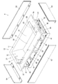
- FIG. 1 is a perspective view showing a bathing apparatus of Example 1.
- FIG. It is a perspective view which shows the state which removed the panel (panel) from the bathing apparatus of Example 1.
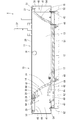
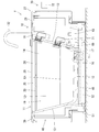
- FIG. It is sectional drawing which shows the state which cut
- It is sectional drawing which shows the state which cut
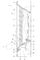
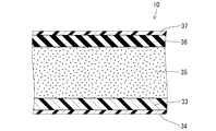
- FIG. It is a schematic sectional drawing which shows the use condition of the bathing apparatus of Example 1. It is a partial expanded sectional view which shows typically the laminated structure of the bathtub of Example 1.
- FIG. It is sectional drawing which shows the state which cut
- the bathing device of the present invention includes a frame that supports the bathtub, and at least a part of the bubble supply device can be attached to the frame.
- this bathing apparatus can support the bathtub by the frame. For this reason, even if the thickness of the bathtub is reduced, the bathtub can be maintained in a predetermined shape.
- this bathing apparatus can attach at least one part of a bubble supply apparatus to a flame
- the cushion layer of the present invention may be made of urethane foam
- the bathtub may include a rubber waterproof layer laminated on the cushion layer surface.
- the cushion layer of the bathtub is made of urethane foam.
- this bathing apparatus has covered the surface side of the cushion layer of the bathtub with the rubber-made waterproof layer. For this reason, the malfunction resulting from the water immersion to a cushion layer can be avoided.
- favorable cushioning properties can be obtained by appropriately setting and combining the elasticity of the rubber of the waterproof layer and the elasticity of the urethane foam of the cushion layer.
- the bathing device may include a hot water storage device that stores hot water in the bathtub so that the water level of the hot water layer does not exceed a predetermined water level.
- the water level of the hot water layer in the bathtub can be made constant by the hot water storage device. For this reason, this bathing apparatus can prevent the height of the foam layer from varying.
- the hot water storage device may include an overflow port formed in the side wall of the bathtub and a hot water supply device that supplies hot water to the bathtub.
- a hot water supply device that supplies hot water to the bathtub.
- the hot water storage device may include a water level sensor that detects the water level of the hot water layer, and a hot water supply device that supplies and stops hot water to the bathtub based on the detection result of the water level sensor.
- a hot water supply device that supplies and stops hot water to the bathtub based on the detection result of the water level sensor.
- the hot water supply from the hot water supply device to the bathtub is continued based on the detection result of the water level sensor.
- the water level of a hot water layer reaches a predetermined water level, supply of the hot water from a hot water supply apparatus to a bathtub will be stopped based on the detection result of a water level sensor. For this reason, in this bathing apparatus, the water level of the hot water layer does not become higher than the predetermined water level.
- the bathing apparatus X of the first embodiment is mainly intended for half-body bathing to obtain a refreshing effect such as a relaxing effect on the mind and body and recovery from fatigue and stress relief.
- this bathing apparatus X can perform a comfortable half-body bath for a long time by the bathtub 10 having a characteristic form and the foam layer Lb formed in the bathtub 10. it can.
- this bathing apparatus X can wash the body in the bathtub 10.
- the bathing apparatus X includes a bathtub 10, a frame 40, and a bubble supply device 60.
- positioned the pillow 26 of the bathtub 10 be a front side.
- the bathtub 10 is obtained by integrating a hot water storage section 11 and a flange section 27.
- the hot water storage section 11 has a box shape with the upper surface opened.
- the flange portion 27 projects outward from the opening edge of the upper surface of the hot water storage portion 11.
- the hot water storage part 11 includes a bottom wall part 12, a pair of left and right symmetrical side wall parts 13, a front wall part 14, and a rear wall part 15.
- the bottom wall portion 12 has a substantially rectangular shape that is long in the front-rear direction.
- the pair of side wall portions 13 rises diagonally outward from the left and right edges of the bottom wall portion 12.
- the front wall portion 14 rises obliquely forward from the front edge portion of the bottom wall portion 12.
- the rear wall portion 15 rises obliquely rearward and upward from the rear edge portion of the bottom wall portion 12.
- Each of the portions where these wall portions are connected is configured by a smooth curved surface.
- the bottom wall 12 has a drainage gradient over the entire region and is substantially horizontal.
- the bottom wall portion 12 has a drain port 16 that is an edge on the right side in the width direction and opens at a substantially central position in the front-rear direction.
- the bottom wall portion 12 has a constant thickness except for the vicinity of the drain port 16.
- the side wall portion 13 has a planar shape over the entire region.
- the side wall portion 13 has a constant thickness over the entire region. Further, the side wall 13 is thinner than the bottom wall 12.
- the right side wall 13 has a water intake port 17 which is an edge at the lower end and opens at a position close to the front end.
- the right side wall portion 13 is an upper end portion and has an overflow port 18 that opens at a substantially central portion in the front-rear direction.
- the front wall portion 14 includes a steeply inclined portion 19 that continues to the bottom wall portion 12 and a gently inclined portion 20 that protrudes forward from the upper edge of the steeply inclined portion 19 at an angle close to the horizontal.
- the steeply inclined portion 19 is curved so as to slightly swell toward the inner surface side of the hot water storage portion 11.
- the steeply inclined portion 19 has the maximum thickness at the lower edge (the edge continuous with the bottom wall portion 12).
- the maximum thickness of the steeply inclined portion 19 is the same as the thickness of the bottom wall portion 12.
- the steeply inclined portion 19 gradually decreases in thickness toward the upper side, and becomes the minimum at the edge of the upper end.
- the minimum thickness dimension of the steeply inclined portion 19 is the same as the thickness of the side wall portion 13.
- the gentle slope 20 has a slight downward slope toward the rear (steep slope 19).
- the gently inclined portion 20 has a constant thickness over the entire region.
- the thickness of the gently inclined portion 20 is the same as the thickness of the upper end of the steeply inclined portion 19.
- the gently inclined portion 20 has a mounting hole 21 penetrating vertically at a central position in the width direction.
- the foaming member 22 has a cylindrical mounting portion 23 whose axis is directed in the up-down direction, and a main body portion 24 that forms a horizontal plate connected to the upper end of the cylindrical mounting portion 23.
- the main body portion 24 communicates with the hollow of the cylindrical attachment portion 23.
- the main body 24 has a foaming opening 25 that opens in a slit-form in the rear end face.
- the foaming member 22 is attached to the bathtub 10 with the cylindrical attachment portion 23 fitted into the attachment hole 21 and the main body portion 24 placed on the gently inclined portion 20.
- a pillow 26 having a plate shape with substantially the same width as that of the gently inclined portion 20 is attached to the gently inclined portion 20 so as to cover the main body portion 24 of the foaming member 22 from above.
- the rear wall portion 15 is curved so as to slightly swell toward the inner surface side of the hot water storage portion 11.
- the rear wall portion 15 has the maximum thickness at the lower edge (the edge continuous with the bottom wall 12).
- the maximum thickness dimension of the rear wall portion 15 is the same as the thickness of the bottom wall portion 12.
- the rear wall portion 15 gradually decreases in thickness toward the upper side, and is minimized at the upper end edge portion.
- the minimum thickness dimension of the rear wall portion 15 is the same as the thickness of the side wall portion 13.
- the flange portion 27 protrudes substantially horizontally outward from the opening edge of the upper surface of the hot water storage portion 11 over the entire circumference.
- the flange part 27 is a rectangle whose outer peripheral shape is long in the front-rear direction.
- the flange portion 27 is substantially horizontal, but is slightly inclined so as to have a downward slope toward the inner side (the hot water storage portion 11 side) over the entire circumference.
- the flange portion 27 has a constant thickness over the entire region, and has the same thickness as the side wall portion 13, the upper end portion of the steeply inclined portion 19, the gently inclined portion 20, and the upper end portion of the rear wall portion 15. is there.
- the right flange 28 protruding rightward from the upper end edge of the right side wall portion 13, and the gently inclined portion from the front end edge of the gently inclined portion 20 of the front wall portion 14.
- Each of the front flanges 29 projecting forward at a position slightly higher than 20 has a relatively large projecting dimension.
- the left flange 30 projecting to the left from the upper end edge of the left side wall portion 13 and the rear flange 31 projecting rearward from the upper end edge of the rear wall portion 15 both project. Is smaller than the right flange 28 and the front flange 29.
- the right flange 28 and the front flange 29 are wide, and the left flange 30 and the rear flange 31 are narrow.
- the right flange 28 is provided with a faucet fitting 32 at a position on the left edge (edge near the hot water storage section 11) and near the rear end.
- the faucet fitting 32 is connected to a hot water supply device (not shown).
- the bathtub 10 has a laminated structure over the entire region.
- the shape of the bathtub 10 is held by a substrate 33 made of FRP (fiber reinforced plastic) (fiber reinforced plastic).
- the substrate 33 has a back surface coating layer 34 formed on the back surface (the outer surface of the hot water storage section 11 and the lower surface of the flange section 27).
- the substrate 33 has a cushion layer 35 made of urethane foam laminated on the surface side.
- the cushion layer 35 has a rubber waterproof layer 36 laminated on the surface side.
- the waterproof layer 36 has a surface coating layer 37 formed on the surface.
- the thickness of the substrate 33, the thickness of the back surface coating layer 34, the thickness of the waterproof layer 36, and the thickness of the front surface coating layer 37 are all uniform over the entire region of the bathtub 10.
- the thickness of the cushion layer 35 differs depending on the part.
- the bathtub 10 including the cushion layer 35 and the rubber waterproof layer 36 is elastically deformed so that the inner surface of the hot water storage section 11 is recessed.
- the bathtub 10 is elastically deformed so that the upper surface of the flange portion 27 is also recessed.
- the frame 40 has four support columns 41 arranged at positions substantially corresponding to the four corners of the bathtub 10.
- the four columns 41 have lower ends connected to each other by two long beams 42 that are long in the front-rear direction and two short beams 43 that are long in the width direction (left-right direction).
- the four support columns 41 are connected at their upper ends by a rectangular frame 45 having a rectangular shape via an extension beam 44 protruding outward in the width direction.
- the pair of left and right reinforcing columns 47 connect a substantially central portion in the length direction of the left and right long beams 42 and a substantially central portion in the length direction of the left and right long side beams 46 of the rectangular frame 45.
- the support beam 48 that is long in the width direction is passed between the left and right long beams 42 at a position slightly behind the front end of the long beam 42 and at a position close to the rear end of the long beam 42.
- the long beams 42 are connected to each other.
- a long ladder beam 49 is extended in the left-right direction at the front end of the long beam 42.
- the frame 40 has a bathtub 10 attached thereto.
- the bottom wall portion 12 is placed on the pair of front and rear support beams 48 at the front and rear edge portions, and the hot water storage portion 11 is fixed.
- the front flange 29 of the flange portion 27 is fixed in a state where it is placed on the short side beam 50 on the front side of the rectangular frame 45.
- the rear flange 31 of the flange portion 27 is fixed in a state where it is placed on the short side beam 50 on the rear side of the square frame 45.
- the right flange 28 of the flange portion 27 is fixed while being placed on the long side beam 46 on the right side of the rectangular frame 45.
- the left flange 30 of the flange portion 27 is fixed in a state where it is placed on the long side beam 46 on the left side of the rectangular frame 45.
- the frame 40 includes two long indentations 51, two short indentations 52, two long aprons 53, and two short aprons 54. And are attached.
- the long indentation 51 is arranged so as to cover a range from the front support column 41 to the rear support column 41 in the front-rear direction, and to cover a range from the lower end of the frame 40 to the upper end of the long beam 42 in the vertical direction. ing.
- the long recess 51 is fixed to the upper surface of the long beam 42 at the upper edge.
- the short dent 52 is arranged so as to cover a range from the right column 41 to the left column 41 in the width direction and to cover a range from the lower end of the frame 40 to the upper end of the short beam 43 in the vertical direction.
- the short dent 52 is fixed to the upper surface of the short beam 43 at the edge of the upper end thereof. These four dents surround the lower end of the frame 40 over the entire circumference.
- the long apron 53 covers a range from the front end to the rear end of the long side beam 46 in the front-rear direction, and extends from the upper end of the long beam 42 to the upper end of the long side beam 46 in the vertical direction. It is arranged so as to cover the range.
- the long apron 53 is fixed to the metal fitting at the upper end portion of the long dent 51 via the metal fitting provided at the lower end portion thereof.
- the long apron 53 has an upper end locked in a gap between the long side beam 46 and the outer edge of the left flange 30 or a gap between the long side beam 46 and the outer edge of the right flange 28. As shown in FIG.
- the short apron 54 covers a range from the right end to the left end of the short side beam 50 in the width direction, and covers a range from the upper end of the short beam 43 to the upper end of the short side beam 50 in the vertical direction.
- the short apron 54 is fixed to the metal fitting at the upper end of the short dent 52 through the metal fitting provided at the lower end thereof.
- the short apron 54 has an upper end locked in a gap between the short side beam 50 and the outer edge portion of the front flange 29 or a gap between the short side beam 50 and the outer edge portion of the rear flange 31.
- These four aprons surround the outer region of the hot water storage section 11 in the region above the depression and the bathtub 10 in the frame 40 over the entire circumference.
- the bubble supply device 60 includes a bubble generation device 61 and a circulation path 64.
- the bubble generating device 61 includes an inflow part 62, an outflow part 63, a foaming path (not shown) from the inflow part 62 to the outflow part 63, and a compressor (not shown) connected to the foaming path.
- the foaming path is provided with a stirring device (not shown) using a mechanism for rotating the stirring blade in the foaming path.
- the circulation path 64 includes an internal space (hot water storage space) of the hot water storage section 11, an inflow path 65 from the intake port 17 of the bathtub 10 to the inflow section 62, and the bubble generator 61.
- the foaming path, the outflow path 66 from the outflow part 63 to the cylindrical mounting part 23 of the foaming member 22, and the foaming member 22 are configured.
- the hot water storage unit 11 pours a predetermined amount of hot water from the faucet fitting 32.
- the hot water storage section 11 stores the foaming liquid (hot water mixed with the foaming agent) up to a predetermined water level by introducing the foaming agent into the poured hot water, thereby forming the hot water layer Lh.
- the foaming liquid stored in the hot water storage section 11 passes through the water intake port 17, the inflow path 65, the foaming path, the outflow path 66, and the foaming member 22 in this order, and passes through the front wall section 14 from the foaming port 25 to the hot water storage section 11. It circulates through the path that flows down.
- the bubble generating device 61 is accommodated in a space formed by the frame 40 (that is, a space surrounded by the aprons 53 and 54) and fixed in a state where it is placed on the ladder beam 49.
- the inflow path 65 and the outflow path 66 constituting the circulation path 64 are also housed in the space formed by the frame 40 (that is, the space surrounded by the aprons 53 and 54), similarly to the bubble generating device 61.
- the hot water storage section 11 and the bubble generating device 61 that constitute the circulation path 64 are also attached to the frame 40.
- the foam member 22 is also attached to the frame 40 via the bathtub 10. Therefore, the bubble supply device 60 is attached to the frame 40 as a whole.
- the circulating foaming liquid is agitated and mixed with the air supplied from the compressor when passing through the foaming path.
- the foaming liquid agent contains air bubbles, and is discharged from the foam outlet 25 into the hot water storage section 11.
- the bubbles contained in the foaming liquid float on the upper surface of the hot water layer Lh to form the foam layer Lb.
- the bubble supply device 60 is stopped.
- the supply of bubbles to the hot water storage unit 11 is completed.
- the bubble state of the foam layer Lb changes with time. That is, the bubbles just supplied to the hot water storage section 11 are in a fine cream shape with a bubble diameter of several tens to several hundreds ⁇ m, but as time passes, the bubbles gradually collapse and the bubble diameter increases. . Further, as the bubble diameter increases, the fluidity of the bubbles decreases due to the separation of moisture from the bubbles. During this time, the bubbles have a meringue state. Eventually, it becomes a light bubble like a cloud that does not feel the weight of flying when you blow. Therefore, as shown in FIG. 6, if bathing in the hot water storage part 11 and taking a half body bath, it is possible to enjoy bubbles in various states, and the bather P can obtain a relaxing effect and a refreshing effect.
- This bathing apparatus X has the following characteristics. (1) When taking a half-body bath, the upper level of the bather P is exposed by lowering the water level of the hot water layer Lh. For this reason, it is necessary to suppress the temperature drop of the hot water in the bathtub 10. In this regard, in this bathing apparatus X, the foam layer Lb that covers the upper surface of the hot water layer Lh functions as a heat insulating layer, so that the temperature drop of the hot water layer Lh can be suppressed.
- the cushion layer 35 constituting the bathtub 10 is made of urethane foam, and this urethane foam also functions as a heat insulating layer. For this reason, the temperature fall of the hot water layer Lh can be suppressed. Furthermore, the urethane foam has a low thermal conductivity. For this reason, the temperature fall of the inner surface of the hot water storage part 11 is suppressed, and when the body of the bather P touches the inner surface of the hot water storage part 11, it does not feel cold.
- this bathing apparatus X covers the upper surface of the hot water layer Lh with the foam layer Lb, generation of steam can be suppressed. Therefore, this bathtub 10 (bathing apparatus X) is suitable not only for a dedicated bathroom but also for installation in a living room or the like.
- the foaming agent is selected from materials that are less irritating to human skin and in which bubbles do not disappear easily. Thereby, half-body bathing for a long time is possible.
- the buoyancy received by the bather P is small because the water level in the bath is relatively low. Therefore, when the half-body bathing is continued for a long time, the body weight is supported by hitting the inner surface of the hot water storage part 11 (particularly, the bottom wall part 12, the steep slope part 19 of the front wall part 14, and the rear wall part 15) of the body. There is a concern that the bather P may feel pain, discomfort, etc. in the part (particularly the buttocks and back).
- the bathtub 10 has a cushion layer 35 and a rubber waterproof layer 36.
- the inner surface of the bathtub 10 is dented so as to become familiar with the body of the bather P according to the weight.
- the contact area between the body and the inner surface of the bathtub 10 is increased, the reaction force per unit area acting on the body side from the bathtub 10 side is reduced, and pain, discomfort, and the like can be reduced.
- the surface of the bathtub 10 is easily dented elastically by the cushion layer 35 and the rubber waterproof layer 36. Because of this elasticity, even if the bather P loses his balance and hits his hand or body against the bathtub 10, the shock is absorbed, so the bather P is less likely to feel uncomfortable.
- the bubble generating device 61 generates vibration accompanying the driving of the compressor, and this vibration is transmitted to the bathtub 10 via the frame 40.
- the bathtub 10 has a cushion layer 35 made of urethane foam. For this reason, vibration transmitted to the outer surface (substrate 33) of the bathtub 10 is absorbed by the cushion layer 35. Therefore, even if the bather P touches the inner surface of the hot water storage part 11 or the upper surface of the flange part 27, it is hard to feel vibration.
- the bathing apparatus X of the first embodiment supplies the bubble 10 for forming the foam layer Lb on the upper surface of the bathtub 10 whose inner surface is deformed by including the cushion layer 35 and the hot water layer Lh in the bathtub 10.
- a bubble supply device 60 is provided. According to this structure, a refreshing effect can be acquired by immersing a body in the hot water layer Lh formed in the bathtub 10, and the foam layer Lb formed on it. Further, the inner surface of the bathtub 10 can be deformed by the cushion layer 35. For this reason, even if it is immersed in the bathtub 10 for a long time, it does not need to memorize pain and discomfort. Furthermore, the temperature drop of the hot water layer Lh is suppressed by the heat insulating effect of the foam layer Lb.
- the bathing apparatus X of Example 1 can continue bathing for a long time in a state of being wrapped in foam, and can obtain a high refreshing effect.
- the bathing apparatus X includes a frame 40 that supports the bathtub 10, and the bubble supply device 60 is attached to the frame 40. Since the bathtub 10 is supported by the frame 40 as described above, the bathtub 10 can be maintained in a predetermined shape even if the thickness of the bathtub 10 is reduced. Further, since the bubble supply device 60 is attached to the frame 40, the frame 40, the bathtub 10, and the bubble supply device 60 are realized as a unit. Thereby, the bathing apparatus X can be installed not only in a dedicated bathroom but also in a living room or the like.
- the bathtub 10 includes a rubber waterproof layer 36 in which the cushion layer 35 is made of urethane foam and is laminated on the surface side of the cushion layer 35.
- the cushion layer 35 is made of urethane foam and is laminated on the surface side of the cushion layer 35.
- the bathing apparatus Y of the second embodiment includes a hot water storage apparatus 70 that stores hot water in the bathtub 10 so that the water level of the hot water layer Lh does not exceed a predetermined water level.
- the hot water storage device 70 With this hot water storage device 70, the water level of the hot water layer Lh in the bathtub 10 can be made constant. For this reason, the bathing apparatus Y can prevent the height of the foam layer Lb from varying. Since other configurations are the same as those in the first embodiment, the same configurations are denoted by the same reference numerals, and descriptions of the structure, operation, and effects are omitted.
- the hot water storage device 70 of the second embodiment includes a low water level overflow port 71 formed in the side wall portion 13 of the hot water storage portion 11 and a hot water supply device 72 for supplying hot water to the bathtub 10.
- the low water level overflow port 71 is disposed at a position lower than the overflow port 18 provided at a high position of the hot water storage section 11 (upper end portion of the side wall section 13).
- the hot water supply device 72 is connected to the faucet fitting 32. When hot water is supplied from the hot water supply device 72 to the hot water storage section 11 through the faucet fitting 32, the water level of the hot water layer Lh in the hot water storage section 11 rises.
- the hot water is discharged from the low water level overflow port 71 to the outside of the hot water storage unit 11 even if hot water continues to be supplied into the hot water storage unit 11 thereafter. For this reason, the hot water layer Lh in the hot water storage part 11 can be kept at a predetermined water level.
- the low water level overflow port 71 can be selected when enjoying bubble bathing, and the upper overflow port 18 can be selected during normal bathing.
- the bathing apparatus Z of the third embodiment includes a hot water storage apparatus 80 that stores hot water in the bathtub 10 so that the water level of the hot water layer Lh does not exceed a predetermined water level.
- the hot water storage device 80 With this hot water storage device 80, the water level of the hot water layer Lh in the bathtub can be made constant. For this reason, it can prevent that the height of the foam layer Lb varies. Since other configurations are the same as those in the first embodiment, the same configurations are denoted by the same reference numerals, and descriptions of the structure, operation, and effects are omitted.
- the hot water storage device 80 includes a water level sensor 81 that detects the water level in the hot water storage unit 11, and a hot water supply device 82 that supplies and stops hot water to the hot water storage unit 11 based on the detection result of the water level sensor 81. ing.
- the hot water supply device 82 is connected to the faucet fitting 32. When hot water is supplied from the hot water supply device 82 to the hot water storage section 11 through the faucet fitting 32, the water level of the hot water layer Lh in the hot water storage section 11 rises. During this time, the water level of the hot water layer Lh is continuously detected by the water level sensor 81. Detection information of the water level sensor 81 is input to a control unit (not shown) of the hot water supply device 82.
- the hot water supply from the hot water supply device 82 to the hot water storage unit 11 is continued based on the detection result of the water level sensor 81. Then, when the water level of the hot water layer Lh reaches a predetermined water level, the supply of hot water from the hot water supply device 82 to the bathtub 10 is stopped based on the detection result of the water level sensor 81. For this reason, it can prevent that the hot water layer Lh water level in the hot water storage part 11 becomes higher than a predetermined water level.
- the present invention is not limited to the first to third embodiments described with reference to the above description and drawings.
- the following embodiments are also included in the technical scope of the present invention.
- the cushioning properties (elasticity and deformation amount) of the bathtub can be changed by changing the composition of the urethane foam constituting the bathtub cushion layer.
- the cushion layer is made of a urethane foam, but the cushion layer may be made of a material other than the urethane foam. By changing the material of the cushion layer, the cushioning properties (elasticity and deformation amount) of the inner surface of the bathtub can be changed.
- the entire bubble supply device is attached to the frame, but only a part of the bubble supply device may be attached to the frame.
- the cushioning properties (elasticity and deformation amount) of the bathtub can be changed by increasing or decreasing the thickness of the cushion layer of the bathtub.
- the thickness of the cushion layer on the bottom wall of the bathtub may be locally varied or may gradually change. In this way, the cushioning properties (elasticity and deformation amount) of the bottom wall can be locally changed or gradually changed.
- the thickness of the cushion layer on the side wall of the bathtub may be locally varied or may gradually change. If it does in this way, the cushioning property (elasticity and deformation amount) of a side wall part can be changed locally, or can be changed gradually.
- the thickness of the cushion layer on the front wall portion and the rear wall portion of the bathtub may be uniform throughout, or may be locally thickened or thinned. .
- the thickness of the cushion layer of the flange portion of the bathtub may be locally varied or may be gradually changed. In this way, the cushioning properties (elasticity and deformation amount) of the flange portion can be locally changed or gradually changed.
- the thickness of the cushion layer on the side wall portion may be the same as the cushion layer on the bottom wall portion, or may be thicker than the cushion layer on the bottom wall portion.
- the thickness of the cushion layer on the side wall portion may be thicker than that of the flange portion, and conversely, it may be thinner than that of the flange portion.
- the thickness of the cushion layer on the side wall portion may be larger than the minimum thickness of the cushion layer on the front wall portion and the rear wall portion.
- the left side wall and the right side wall may be asymmetrical.
- the thickness of the front wall portion may be constant over the entire region of the front wall portion.
- the thickness of the front wall portion may be the same as any of the bottom wall portion, the side wall portion, and the flange portion, or may be different from any of the bottom wall portion, the side wall portion, and the flange portion.
- the thickness of the rear wall portion may be constant over the entire region of the rear wall portion. In this case, the thickness of the rear wall portion may be the same as any of the bottom wall portion, the side wall portion, and the flange portion, or may be different from any of the bottom wall portion, the side wall portion, and the flange portion. .
- the front wall portion and the rear wall portion may be asymmetrical in the front-rear direction.
- the cushion layer of the flange portion may have the same thickness as the cushion layer of the bottom wall portion, or may be thicker than the cushion layer of the bottom wall portion.
- the cushion layer is provided in the entire region of the hot water storage section. However, the cushion layer may be provided only in a part of the hot water storage section.
- the cushion layer is provided in the entire region of the flange portion, but the cushion layer may be provided only in a partial region of the flange portion.
- the cushion layer is provided on both the hot water storage portion and the flange portion, but the cushion layer may be provided only on the hot water storage portion.
- the inner surface (upper surface) of the bottom wall portion has no large unevenness, but the inner surface of the bottom wall portion may have unevenness.
- the concave portion or the convex portion may be configured to be continuous with the side wall portion, the front wall portion, or the rear wall portion, or may be configured not to be continuous with these wall portions.
- a large unevenness is not present on the inner surface of the side wall, but the unevenness may be present on the inner surface of the side wall.
- the concave portion or the convex portion may be connected to the bottom wall portion, the front wall portion, the rear wall portion, or the flange portion, or may not be connected to the bottom wall portion, the front wall portion, the rear wall portion, or the flange portion. Also good. (22) In Examples 1 to 3, the inner surface of the front wall portion has no large unevenness, but the inner surface of the front wall portion may have unevenness. In this case, the concave portion or the convex portion may be configured to be continuous with the bottom wall portion, the side wall, or the flange portion, or may be configured not to be continuous with the bottom wall portion, the side wall, or the flange portion.
- the inner surface of the rear wall portion has no large unevenness, but the inner surface of the rear wall portion may have unevenness.
- the concave portion or the convex portion may be configured to be continuous with the bottom wall portion, the side wall portion, or the flange portion, or may be configured not to be continuous with the bottom wall portion, the side wall portion, or the flange portion.
- the foaming liquid stored in the bathtub was circulated through the path through the foaming device to supply the bubbles to the bathtub, but the hot water stored in the bathtub was circulated. Alternatively, air bubbles obtained by mixing hot water supplied from clean water and a blowing agent may be supplied to the bathtub.
Landscapes
- Health & Medical Sciences (AREA)
- Public Health (AREA)
- Epidemiology (AREA)
- General Health & Medical Sciences (AREA)
- Pain & Pain Management (AREA)
- Physical Education & Sports Medicine (AREA)
- Rehabilitation Therapy (AREA)
- Life Sciences & Earth Sciences (AREA)
- Animal Behavior & Ethology (AREA)
- Veterinary Medicine (AREA)
- Bathtubs, Showers, And Their Attachments (AREA)
- Devices For Medical Bathing And Washing (AREA)
Abstract
長時間の入浴を可能としたリフレッシュ効果の高い入浴装置を提供する。 入浴装置(X)は、クッション層(35)を備えることで内面が変形する浴槽(10)と、浴槽(10)内の湯層(Lh)の上面に泡層(Lb)を形成するための気泡を供給する気泡供給装置(60)とを備えている。
Description
本発明は、入浴装置に関するものである。
特許文献1は従来の入浴装置を開示している。この入浴装置は、お湯が貯められている浴槽に泡を投入し、その泡でお湯の表面を覆い隠す。この入浴装置は浴槽内で身体の汚れを洗い流すことを目的としている。このため、この入浴装置は洗剤成分を含む泡を用いている。
ところで、入浴装置は、単に身体を洗うためだけではなく、疲労回復やストレス解消(stress-relieving)等のリフレッシュ効果(refreshing effect)を目的とした半身浴に使用することがある。このようなリフレッシュ効果を目的とした半身浴において、特許文献1に記載の泡で身体を包み込むことは、効果的である。
リフレッシュ効果を目的とした半身浴は、浴槽のお湯に浸かっている時間が長時間に亘ることが多い。ところが、特許文献1に記載された入浴装置は、半身浴を目的としたものではなく、身体の汚れを洗い流すことを目的としている。また、一般的な浴槽は表面の硬い樹脂製である。しかも、半身浴をする際、浴槽内に溜めるお湯の量は少ない。このため、入浴者の身体に働く浮力が小さい。よって、長時間に亘って半身浴を続けると、身体のうち浴槽に当たっているお尻や背中等に痛みや不快感を覚えることが懸念される。したがって、特許文献1に記載された入浴装置は、リフレッシュ効果のために長時間に亘って入浴するには適していない。
本発明は上記のような事情に基づいて完成されたものであって、長時間の入浴を可能としたリフレッシュ効果の高い入浴装置を提供することを目的とする。
本発明の入浴装置は、クッション層(cushion layer)を備えることで内面が変形する浴槽と、
前記浴槽内の湯層の上面に泡層を形成するための気泡を供給する気泡供給装置とを備えていることを特徴とする。
前記浴槽内の湯層の上面に泡層を形成するための気泡を供給する気泡供給装置とを備えていることを特徴とする。
この入浴装置は、気泡供給装置によって浴槽内の湯層の上に泡層を形成する。このため、この湯層と泡層に身体を浸けることによってリフレッシュ効果を得ることができる。また、浴槽は内面がクッション層によって変形し得る。このため、長時間に亘って浴槽内に浸かっても、痛みや不快感を覚えずに済む。さらに、泡層の断熱効果によって湯層の温度低下が抑えられる。
したがって、本発明の入浴装置は、泡に包まれた状態で長時間に亘って入浴を続けることが可能となり、高いリフレッシュ効果を得ることができる。
本発明の入浴装置における好ましい実施の形態を説明する。
本発明の入浴装置は、前記浴槽を支持するフレーム(frame)を備えており、フレームに気泡供給装置の少なくとも一部が取り付けられ得る。この場合、この入浴装置は浴槽をフレームによって支持することができる。このため、浴槽の肉厚を薄くしても、浴槽を所定の形状に保つことができる。また、この入浴装置はフレームに気泡供給装置の少なくとも一部を取り付けることができる。このため、フレーム、浴槽、及び気泡供給装置の少なくとも一部をユニット(unit)化することができる。
本発明のクッション層はウレタン発泡体(urethane foam)によって構成され、浴槽はクッション層の表面側に積層されたゴム(rubber)製の防水層を備え得る。この場合、この入浴装置は浴槽のクッション層がウレタン発泡体によって構成されている。このため、このウレタン発泡体の断熱効果によって、浴槽内の温度低下を抑えることができる。また、この入浴装置は浴槽のクッション層の表面側をゴム製の防水層で覆っている。このため、クッション層への浸水に起因する不具合を回避できる。また、防水層のゴムの弾性とクッション層のウレタン発泡体の弾性とを適宜に設定して組み合わせることによって、良好なクッション性を得ることができる。
入浴装置は、湯層の水位が所定水位を超えないように浴槽内に湯を貯める貯湯装置を備え得る。この場合、貯湯装置によって浴槽内の湯層の水位を一定にすることができる。このため、この入浴装置は泡層の高さがばらつくのを防止することができる。
貯湯装置は、浴槽の側壁部に形成したオーバーフロー口(overflow port)と、浴槽に湯を供給する給湯装置とを備え得る。この場合、給湯装置から浴槽内に湯を供給して湯層の水位が所定高さになると、それ以降は、浴槽内に供給される湯がオーバーフロー口から浴槽外へ排出される。このため、この入浴装置は湯層の水位が所定水位よりも高くなることはない。
貯湯装置は、湯層の水位を検知する水位センサ(water level sensor)、水位センサの検知結果に基づいて浴槽への湯の供給及び停止を行う給湯装置とを備え得る。この場合、湯層の水位が所定高さよりも低いと、水位センサの検知結果に基づいて給湯装置から浴槽へ湯の供給を続ける。そして、湯層の水位が所定水位に達すると、水位センサの検知結果に基づいて給湯装置から浴槽への湯の供給を停止する。このため、この入浴装置は湯層の水位が所定水位よりも高くなることはない。
次に、本発明の入浴装置を具体化した実施例1~3について、図面を参照しつつ説明する。
<実施例1>
実施例1の入浴装置Xは心身のリラックス効果(relaxing effect)や疲労回復やストレス解消等のリフレッシュ効果を得るための半身浴を主たる目的としている。図1~図7に示すように、この入浴装置Xは、特徴的な形態の浴槽10と、浴槽10内に形成する泡層Lbとによって、快適な半身浴を長時間に亘って行うことができる。勿論、この入浴装置Xは浴槽10内で身体を洗うこともできる。入浴装置Xは、図3,5,6に示すように、浴槽10と、フレーム40と、気泡供給装置60とを備えている。尚、以下の説明における入浴装置X(浴槽10)の前後方向については、浴槽10の枕26を配置している側を前側とする。
実施例1の入浴装置Xは心身のリラックス効果(relaxing effect)や疲労回復やストレス解消等のリフレッシュ効果を得るための半身浴を主たる目的としている。図1~図7に示すように、この入浴装置Xは、特徴的な形態の浴槽10と、浴槽10内に形成する泡層Lbとによって、快適な半身浴を長時間に亘って行うことができる。勿論、この入浴装置Xは浴槽10内で身体を洗うこともできる。入浴装置Xは、図3,5,6に示すように、浴槽10と、フレーム40と、気泡供給装置60とを備えている。尚、以下の説明における入浴装置X(浴槽10)の前後方向については、浴槽10の枕26を配置している側を前側とする。
<浴槽10>
図1~4に示すように、浴槽10は貯湯部11とフランジ部(flange)27とを一体化したものである。貯湯部11は上面を開放した箱形である。フランジ部27は貯湯部11の上面の開口縁から外方へ張り出している。貯湯部11は、底壁部12、左右対称な一対の側壁部13、前壁部14、及び後壁部15を備えている。底壁部12は前後方向に長い略長方形である。一対の側壁部13は底壁部12左右両側の縁部から斜め外側上方へ立ちあがっている。前壁部14は底壁部12の前縁部から斜め前側上方へ立ち上がっている。後壁部15は底壁部12の後縁部から斜め後側上方へ立ち上がっている。これらの壁部が連なる部分は、いずれも、滑らかな曲面で構成されている。
図1~4に示すように、浴槽10は貯湯部11とフランジ部(flange)27とを一体化したものである。貯湯部11は上面を開放した箱形である。フランジ部27は貯湯部11の上面の開口縁から外方へ張り出している。貯湯部11は、底壁部12、左右対称な一対の側壁部13、前壁部14、及び後壁部15を備えている。底壁部12は前後方向に長い略長方形である。一対の側壁部13は底壁部12左右両側の縁部から斜め外側上方へ立ちあがっている。前壁部14は底壁部12の前縁部から斜め前側上方へ立ち上がっている。後壁部15は底壁部12の後縁部から斜め後側上方へ立ち上がっている。これらの壁部が連なる部分は、いずれも、滑らかな曲面で構成されている。
図3~6に示すように、底壁部12は、全領域に亘り排水勾配を持たせ、略水平である。図1に示すように、底壁部12は幅方向における右側の縁部であって前後方向における略中央位置に開口する排水口16を有している。底壁部12は厚さが排水口16の近傍を除いて一定である。側壁部13はその全領域に亘って平面状をなしている。側壁部13は厚さが全領域に亘って一定である。また、側壁部13は厚さが底壁部12よりも薄い。図1,3に示すように、右側の側壁部13は下端の縁部であって前端に近い位置に開口する取水口17を有している。右側の側壁部13は上端部であって前後方向における略中央部に開口するオーバーフロー口18を有している。
図5に示すように、前壁部14は、底壁部12に連なる急傾斜部19と、急傾斜部19の上端縁から前方へ水平に近い角度で張り出す緩傾斜部20とからなる。急傾斜部19は貯湯部11の内面側に向かって僅かに膨らむように湾曲している。急傾斜部19は厚さがその下端の縁部(底壁部12に連なる縁部)において最大である。急傾斜部19の最大厚さ寸法は底壁部12の厚さと同じである。急傾斜部19は、厚さが上方に向かって次第に薄くなり、上端の縁部において最小となる。急傾斜部19の最小厚さ寸法は、側壁部13の厚さと同じである。緩傾斜部20は、後方(急傾斜部19)に向かって僅かに下り勾配となっている。緩傾斜部20は厚さが全領域に亘って一定である。緩傾斜部20の厚さ寸法は急傾斜部19の上端部の厚さと同じである。
図5に示すように、緩傾斜部20は幅方向の中央位置に上下に貫通した取付孔21を有している。吐泡部材22は、軸線を上下方向に向けた筒状取付部23と、筒状取付部23の上端に連なる水平な板状をなす本体部24とを有している。本体部24は筒状取付部23の中空に連通している。また、本体部24は後端面において水平なスリット状(slit-form)に開口する吐泡口25を有している。この吐泡部材22は、筒状取付部23を取付孔21に嵌入するとともに、本体部24を緩傾斜部20に載置した状態で、浴槽10に取り付けている。さらに、緩傾斜部20には、吐泡部材22の本体部24を上から覆い隠すようにして、緩傾斜部20とほぼ同じ幅寸法の板状をなす枕26が取り付けられている。
図3に示すように、後壁部15は貯湯部11の内面側に向かって僅かに膨らむように湾曲している。後壁部15は厚さが下端の縁部(底壁部12に連なる縁部)において最大である。後壁部15の最大厚さ寸法は底壁部12の厚さと同じである。後壁部15は、厚さが上方に向かって次第に薄くなり、上端縁部において最小となる。後壁部15の最小厚さ寸法は側壁部13の厚さと同じである。
図3~6に示すように、フランジ部27は貯湯部11の上面の開口縁から全周に亘って略水平外向きに張り出している。フランジ部27は外周形状が前後方向に長い長方形である。フランジ部27は、概ね水平であるが、全周に亘り内側(貯湯部11側)に向かって下り勾配となるように僅かに傾斜している。また、フランジ部27は、厚さ寸法が全領域に亘って一定であり、側壁部13、急傾斜部19の上端部、緩傾斜部20、及び後壁部15の上端部と同じ厚さである。
図1,2に示すように、フランジ部27のうち、右側の側壁部13の上端縁から右方へ張り出す右フランジ28、及び前壁部14の緩傾斜部20の前端縁から緩傾斜部20より少し高い位置で前方へ張り出す前フランジ29は、いずれも張り出し寸法が比較的大きい。これに対し、フランジ部27のうち、左側の側壁部13の上端縁から左方へ張り出す左フランジ30、及び後壁部15の上端縁から後方へ張り出す後フランジ31は、いずれも張り出し寸法が右フランジ28及び前フランジ29よりも小さい。つまり、右フランジ28及び前フランジ29は幅広で、左フランジ30及び後フランジ31は幅狭である。右フランジ28は、左側の縁部(貯湯部11に近い縁部)であって後端部に近い位置に水栓金具32を設けている。水栓金具32は給湯装置(図示省略)に接続している。
図7に示すように、浴槽10は、その全領域に亘って積層構造をなしている。浴槽10は、FRP(fiber reinforced plastic)(繊維強化プラスチック)からなる基板33によって形状が保持されている。基板33は裏面(貯湯部11の外面、及びフランジ部27の下面)に裏面用塗膜層34を形成している。基板33は表面側にウレタン発泡体からなるクッション層35を積層している。クッション層35は表面側にゴム製の防水層36を積層している。防水層36は表面に表面用塗膜層37を形成している。基板33の厚さ、裏面用塗膜層34の厚さ、防水層36の厚さ、及び表面用塗膜層37の厚さは、いずれも、浴槽10の全領域に亘って均一である。一方、クッション層35は部位によって厚さが異なっている。このようなクッション層35とゴム製の防水層36とを備えた浴槽10は、貯湯部11の内面が凹むように弾性変形する。また、この浴槽10はフランジ部27の上面も凹むように弾性変形する。
<フレーム40>
図2~4に示すように、フレーム40は、浴槽10の四隅とほぼ対応する位置に配置された4本の支柱41を有している。4本の支柱41は、前後方向に長い2本の長尺梁42と、幅方向(左右方向)に長い2本の短尺梁43とによって、下端部同士を連結している。また、4本の支柱41は、幅方向外向きに突出する拡張梁44を介して、長方形をなす方形枠45によって、上端部を連結している。左右一対の補強柱47は、左右の長尺梁42の長さ方向における略中央部と、方形枠45の左右の長辺梁46の長さ方向における略中央部とを連結している。幅方向に長い支持梁48は、長尺梁42の前端よりも少し後方の位置、及び長尺梁42の後端に近い位置において、左右の長尺梁42の間に差し渡され、左右の長尺梁42同士を連結している。長尺梁42の前端部において、左右方向に長い梯子梁49が差し渡されている。
図2~4に示すように、フレーム40は、浴槽10の四隅とほぼ対応する位置に配置された4本の支柱41を有している。4本の支柱41は、前後方向に長い2本の長尺梁42と、幅方向(左右方向)に長い2本の短尺梁43とによって、下端部同士を連結している。また、4本の支柱41は、幅方向外向きに突出する拡張梁44を介して、長方形をなす方形枠45によって、上端部を連結している。左右一対の補強柱47は、左右の長尺梁42の長さ方向における略中央部と、方形枠45の左右の長辺梁46の長さ方向における略中央部とを連結している。幅方向に長い支持梁48は、長尺梁42の前端よりも少し後方の位置、及び長尺梁42の後端に近い位置において、左右の長尺梁42の間に差し渡され、左右の長尺梁42同士を連結している。長尺梁42の前端部において、左右方向に長い梯子梁49が差し渡されている。
図2~4に示すように、このフレーム40は浴槽10を取り付けている。浴槽10をフレーム40に取り付けると、底壁部12がその前後両端の縁部において、前後一対の支持梁48に載置された状態になり、貯湯部11が固定される。フランジ部27の前フランジ29は方形枠45の前側の短辺梁50に載置された状態で固定される。フランジ部27の後フランジ31は方形枠45の後側の短辺梁50に載置された状態で固定される。フランジ部27の右フランジ28は方形枠45の右側の長辺梁46に載置された状態で固定される。フランジ部27の左フランジ30は方形枠45の左側の長辺梁46に載置された状態で固定される。
図1~5に示すように、フレーム40は、2枚の長尺けこみ51と、2枚の短尺けこみ52と、2枚の長尺エプロン(aprons)53と、2枚の短尺エプロン54とを取り付けている。長尺けこみ51は、前後方向において前側の支柱41から後側の支柱41に亘る範囲を覆い、上下方向においてはフレーム40の下端から長尺梁42の上端に亘る範囲を覆うように配置されている。長尺けこみ51は、その上端の縁部において長尺梁42の上面に固定されている。短尺けこみ52は、幅方向において右側の支柱41から左側の支柱41に亘る範囲を覆い、上下方向においてはフレーム40の下端から短尺梁43の上端に亘る範囲を覆うように配置されている。短尺けこみ52は、その上端の縁部において短尺梁43の上面に固定されている。これら4枚のけこみは、フレーム40の下端部を全周に亘って包囲している。
図4に示すように、長尺エプロン53は、前後方向において長辺梁46の前端から後端に亘る範囲を覆い、上下方向においては長尺梁42の上端から長辺梁46の上端に亘る範囲を覆うように配置されている。長尺エプロン53は、その下端部に設けた金具を介して長尺けこみ51の上端部の金具に固定されている。長尺エプロン53は、長辺梁46と左フランジ30の外縁部との隙間又は長辺梁46と右フランジ28の外縁部との隙間に上端部を係止している。図3に示すように、短尺エプロン54は、幅方向において短辺梁50の右端から左端に亘る範囲を覆い、上下方向においては短尺梁43の上端から短辺梁50の上端に亘る範囲を覆うように配置されている。短尺エプロン54は、その下端部に設けた金具を介して短尺けこみ52の上端部の金具に固定されている。短尺エプロン54は、短辺梁50と前フランジ29の外縁部との隙間又は短辺梁50と後フランジ31の外縁部との隙間に上端部を係止している。これらの4枚のエプロンは、フレーム40のうち、けこみよりも上方の領域及び浴槽10のうち貯湯部11の外面を全周に亘って包囲している。
<気泡供給装置60>
図5,6に示すように、気泡供給装置60は、気泡発生装置61と循環路64とを備えている。気泡発生装置61は、流入部62と、流出部63と、流入部62から流出部63に至る製泡路(図示省略)と、製泡路に接続されたコンプレッサ(compressor)(図示省略)とを有している。また、製泡路は製泡路内で撹拌翼を回転させる機構を用いた撹拌装置(図示省略)を途中に設けている。
図5,6に示すように、気泡供給装置60は、気泡発生装置61と循環路64とを備えている。気泡発生装置61は、流入部62と、流出部63と、流入部62から流出部63に至る製泡路(図示省略)と、製泡路に接続されたコンプレッサ(compressor)(図示省略)とを有している。また、製泡路は製泡路内で撹拌翼を回転させる機構を用いた撹拌装置(図示省略)を途中に設けている。
図3,5,6に示すように、循環路64は、貯湯部11の内部空間(貯湯空間)と、浴槽10の取水口17から流入部62に至る流入路65と、気泡発生装置61内の製泡路と、流出部63から吐泡部材22の筒状取付部23に至る流出路66と、吐泡部材22とによって構成している。貯湯部11は所定量の湯を水栓金具32から流しこむ。貯湯部11は流しこまれた湯内に発泡剤を投入することによって、所定水位まで発泡用液剤(発泡剤が混入された湯)を貯めて、湯層Lhを形成する。貯湯部11に貯めた発泡用液剤は、取水口17、流入路65、製泡路、流出路66及び吐泡部材22を順に通り、吐泡口25から前壁部14を伝って貯湯部11内に流れ落ちる経路を循環する。
気泡発生装置61は、フレーム40によって構成する空間(つまり、エプロン53,54によって囲まれた空間)内に収容し、梯子梁49に載置した状態で固定している。循環路64を構成する流入路65及び流出路66も、気泡発生装置61と同様に、フレーム40によって構成する空間(つまり、エプロン53,54によって囲まれた空間)内に収容している。循環路64を構成する貯湯部11、及び気泡発生装置61も、フレーム40に取り付けている。吐泡部材22も、浴槽10を介してフレーム40に取り付けている。したがって、気泡供給装置60は、その全体をフレーム40に取り付けている。
<作用>
この入浴装置Xの使用方法を説明する。半身浴をする際には、まず、水栓金具32から貯湯部11内へ適量の湯を入れ、その湯の中に発泡剤を投入して発泡用液剤を作る。これによって、貯湯部11内に所定水位の湯層Lh(発泡用液剤の層)を形成する。次に、気泡供給装置60を起動する。すると、貯湯部11内の発泡用液剤が、取水口17、流入路65、気泡発生装置61内の製泡路、流出路66、吐泡部材22を順に通過して貯湯部11に戻る経路を循環する。
この入浴装置Xの使用方法を説明する。半身浴をする際には、まず、水栓金具32から貯湯部11内へ適量の湯を入れ、その湯の中に発泡剤を投入して発泡用液剤を作る。これによって、貯湯部11内に所定水位の湯層Lh(発泡用液剤の層)を形成する。次に、気泡供給装置60を起動する。すると、貯湯部11内の発泡用液剤が、取水口17、流入路65、気泡発生装置61内の製泡路、流出路66、吐泡部材22を順に通過して貯湯部11に戻る経路を循環する。
循環する発泡用液剤は、製泡路を通過する際に、コンプレッサから供給した空気が混入するともに撹拌される。これによって、発泡用液剤は、気泡を含んだ状態になり、吐泡口25から貯湯部11内へ吐出される。発泡用液剤が貯湯部11に戻ると、発泡用液剤に含まれていた気泡は、湯層Lhの上面に浮かんで泡層Lbを形成する。泡層Lbが所定の厚さになったところで、気泡供給装置60を停止する。以上により、貯湯部11への気泡の供給が完了する。
この後、時間の経過に伴い、泡層Lbの気泡の状態が変化する。即ち、貯湯部11に供給されたばかりの気泡は、泡径が数10~数100μmの微細なクリーム状のものであるが、時間が経過すると、気泡が徐々に崩れ、泡径が大きくなっていく。また、泡径が大きくなるのに伴い、気泡から水分が分離することによって気泡の流動性が低くなっていく。この間に、気泡はメレンゲ状(meringue state)となる。そして、最終的には、息を吹きかけると飛んでいくような重さを感じない雲のような軽い泡となる。よって、図6に示すように、この貯湯部11に浸かって半身浴をすれば、様々な状態の気泡を楽しむことができ、入浴者Pは、リラックス効果とリフレッシュ効果を得ることができる。
入浴中、幅広の右フランジ28及び前フランジ29に、飲み物、雑誌、テレビ、携帯電話等、リラックス・リフレッシュするのに必要なものを濡らさずに置いておくことができる。また、入浴者Pは、脚を貯湯部11内に漬けた状態でフランジ部27に坐ることもできる。さらに、入浴者P以外の人も、フランジ部27に坐ることができる。
この入浴装置Xは、次のような特徴を有する。
(1)半身浴をする場合、湯層Lhの水位を低くして入浴者Pの上半身が露出する。このため、浴槽10内の湯の温度低下を抑えることが必要である。この点に関して、この入浴装置Xは、湯層Lhの上面を覆う泡層Lbが断熱層として機能するので、湯層Lhの温度低下を抑えることができる。
(1)半身浴をする場合、湯層Lhの水位を低くして入浴者Pの上半身が露出する。このため、浴槽10内の湯の温度低下を抑えることが必要である。この点に関して、この入浴装置Xは、湯層Lhの上面を覆う泡層Lbが断熱層として機能するので、湯層Lhの温度低下を抑えることができる。
(2)浴槽10を構成するクッション層35はウレタン発泡体からなり、このウレタン発泡体も断熱層として機能する。このため、湯層Lhの温度低下を抑えることができる。さらに、ウレタン発泡体は熱伝導率が低い。このため、貯湯部11の内面の温度低下を抑え、入浴者Pの身体が貯湯部11の内面に触れたときに冷たさを感じることもない。
(3)湯層Lhの温度が浴槽10近傍の雰囲気温度より高いと、湯層Lhから生じた湯気による湿度上昇が懸念される。しかし、この入浴装置Xは、湯層Lhの上面を泡層Lbで覆っているので、湯気の発生を抑えることができる。したがって、この浴槽10(入浴装置X)は、専用の浴室に限らず、リビングルーム等への設置にも適している。
(4)発泡剤として、人の肌への刺激が少なく、気泡が消滅し難い材料のものを選択している。これにより、長時間に亘る半身浴が可能になっている。
(5)半身浴をする場合、湯槽の水位が比較的低いため、入浴者Pが受ける浮力は小さい。このため、半身浴を長時間に亘って続けた場合、身体のうち貯湯部11の内面(特に、底壁部12、前壁部14の急傾斜部19、後壁部15)に当たって体重を支えている部分(特に、臀部や背中)において、入浴者Pが痛みや不快感等を覚えることが懸念される。しかし、この入浴装置Xは、浴槽10がクッション層35及びゴム製の防水層36を有している。このため、入浴者Pの体重が浴槽10の内面に作用すると、浴槽10の内面が、体重に応じて入浴者Pの身体に馴染むように凹む。これによって、身体と浴槽10の内面との接触面積が大きくなり、浴槽10側から身体側に作用する単位面積当たりの反力が低減し、痛みや不快感等を軽減することができる。
(6)貯湯部11は、入浴者Pの体重により、底壁部12のうち臀部が当たっている部分が凹むように変形すると、その凹み形状が臀部の滑り防止効果を発揮する。したがって、入浴者Pの身体が底壁部12上で滑る虞がなく、入浴者Pの位置と姿勢が安定する。
(7)入浴者Pが、貯湯部11内に脚を入れた状態でフランジ部27に腰掛けると、入浴者Pの体重によって、フランジ部27のうち臀部が当たっている部分が凹むように変形する。この場合も、凹み形状が臀部の滑り防止効果を発揮するので、入浴者Pがフランジ部27上で滑り難い。
(8)浴槽10は、表面がクッション層35とゴム製の防水層36とによって弾性的に凹み易くなっている。この弾力性によって、入浴者Pがバランスを崩す等して浴槽10に手や身体をぶつけても、その衝撃を吸収するので、入浴者Pが不快感を覚え難い。
(9)気泡発生装置61はコンプレッサの駆動に伴う振動を発生し、この振動はフレーム40を介して浴槽10に伝わる。しかし、浴槽10はウレタン発泡体からなるクッション層35を有している。このため、浴槽10の外面(基板33)に伝わった振動はクッション層35で吸収される。したがって、入浴者Pが貯湯部11の内面やフランジ部27の上面に触れても、振動を感じ難い。
(10)貯湯部11を構成する前壁部14の急傾斜部19や後壁部15は、入浴者Pの背もたれとして利用される。このため、入浴者Pからの繰り返し荷重によって凹むように変形したままになることが懸念される。しかし、この入浴装置Xは、前壁部14と後壁部15に傾斜を付けているので、通常の浴槽のように垂直に近い角度で立ち上がっているものに比べて体重の負荷が分散され、入浴者Pが背もたれとして利用しても、急傾斜部19や後壁部15が凹むように変形したままになる虞はない。
上述のように実施例1の入浴装置Xは、クッション層35を備えることで内面が変形する浴槽10と、浴槽10内の湯層Lhの上面に泡層Lbを形成するための気泡を供給する気泡供給装置60とを備えている。この構成によれば、浴槽10内に形成された湯層Lhとその上に形成された泡層Lbに身体を浸けることによって、リフレッシュ効果を得ることができる。また、浴槽10は内面がクッション層35によって変形し得るようになっている。このため、長時間に亘って浴槽10内に浸かっても、痛みや不快感を覚えずに済む。さらに、泡層Lbの断熱効果によって湯層Lhの温度低下が抑えられる。
したがって、実施例1の入浴装置Xは、泡に包まれた状態で長時間に亘って入浴を続けることが可能となり、高いリフレッシュ効果を得ることができる。
また、入浴装置Xは、浴槽10を支持するフレーム40を備えており、フレーム40に気泡供給装置60を取り付けている。このように浴槽10をフレーム40によって支持したことにより、浴槽10の肉厚を薄くしても、浴槽10を所定の形状に保つことができる。また、フレーム40に気泡供給装置60を取り付けたので、フレーム40と浴槽10と気泡供給装置60をユニット化することを実現している。これによって、入浴装置Xは、専用の浴室に限らず、リビング等に設置することが可能となっている。
また、浴槽10は、クッション層35をウレタン発泡体によって構成し、クッション層35の表面側に積層されたゴム製の防水層36を備えている。このように、クッション層35をウレタン発泡体としたことにより、ウレタン発泡体の断熱効果によって、浴槽10内の温度低下を抑えることができる。また、クッション層35の表面側をゴム製の防水層36で覆っているので、クッション層35への浸水に起因する不具合を回避できる。また、防水層36のゴムの弾性、及びクッション層35のウレタン発泡体の弾性を適宜に設定して組み合わせることによって、良好なクッション性を得ることができる。
<実施例2>
実施例2の入浴装置Yは、図8に示すように、湯層Lhの水位が所定水位を超えないように浴槽10内に湯を貯める貯湯装置70を備えている。この貯湯装置70によって浴槽10内の湯層Lhの水位を一定にすることができる。このため、入浴装置Yは泡層Lbの高さがばらつくことを防止することができる。他の構成については実施例1と同じであるため、同じ構成については、同一符号を付し、構造、作用及び効果の説明は省略する。
実施例2の入浴装置Yは、図8に示すように、湯層Lhの水位が所定水位を超えないように浴槽10内に湯を貯める貯湯装置70を備えている。この貯湯装置70によって浴槽10内の湯層Lhの水位を一定にすることができる。このため、入浴装置Yは泡層Lbの高さがばらつくことを防止することができる。他の構成については実施例1と同じであるため、同じ構成については、同一符号を付し、構造、作用及び効果の説明は省略する。
実施例2の貯湯装置70は、貯湯部11の側壁部13に形成した低水位用オーバーフロー口71と、浴槽10に湯を供給する給湯装置72とを備えている。低水位用オーバーフロー口71は、貯湯部11の高い位置(側壁部13の上端部)に設けられているオーバーフロー口18よりも低い位置に配置している。給湯装置72は水栓金具32に接続している。給湯装置72から水栓金具32を経て貯湯部11に湯を供給すると、貯湯部11内の湯層Lhの水位が上昇する。そして、その水位が低水位用オーバーフロー口71に達すると、これ以降は、貯湯部11内に湯を供給し続けても、低水位用オーバーフロー口71から湯が貯湯部11外へ排出される。このため、貯湯部11内の湯層Lhを所定の水位に保つことができる。このように、泡入浴を楽しむ際は低水位用オーバーフロー口71を選択し、通常の入浴の際は上部のオーバーフロー口18を選択することができる。
<実施例3>
実施例3の入浴装置Zは、図9に示すように、湯層Lhの水位が所定水位を超えないように浴槽10内に湯を貯める貯湯装置80を備えている。この貯湯装置80によって浴槽内の湯層Lhの水位を一定にすることができる。このため、泡層Lbの高さがばらつくのを防止することができる。他の構成については実施例1と同じであるため、同じ構成については、同一符号を付し、構造、作用及び効果の説明は省略する。
実施例3の入浴装置Zは、図9に示すように、湯層Lhの水位が所定水位を超えないように浴槽10内に湯を貯める貯湯装置80を備えている。この貯湯装置80によって浴槽内の湯層Lhの水位を一定にすることができる。このため、泡層Lbの高さがばらつくのを防止することができる。他の構成については実施例1と同じであるため、同じ構成については、同一符号を付し、構造、作用及び効果の説明は省略する。
実施例3の貯湯装置80は、貯湯部11内の水位を検知する水位センサ81と、水位センサ81の検知結果に基づいて貯湯部11への湯の供給及び停止を行う給湯装置82とを備えている。給湯装置82は水栓金具32に接続している。給湯装置82から水栓金具32を経て貯湯部11に湯を供給すると、貯湯部11内の湯層Lhの水位が上昇する。この間、湯層Lhの水位を水位センサ81によって検知し続ける。水位センサ81の検知情報は給湯装置82の制御部(図示省略)に入力される。湯層Lhの水位が所定高さよりも低いと、水位センサ81の検知結果に基づいて、給湯装置82から貯湯部11へ湯の供給を続ける。そして、湯層Lhの水位が所定水位に達すると、水位センサ81の検知結果に基づいて給湯装置82から浴槽10への湯の供給を停止する。このため、貯湯部11内の湯層Lh水位が所定水位よりも高くなることを防止することができる。
<他の実施例>
本発明は上記記述及び図面によって説明した実施例1~3に限定されるものではなく、例えば次のような実施例も本発明の技術的範囲に含まれる。
(1)実施例1~3において、浴槽のクッション層を構成するウレタン発泡体の組成を変えることにより、浴槽のクッション性(弾力や変形量)を変えることができる。
(2)実施例1~3では、クッション層をウレタン発泡体で構成したが、クッション層はウレタン発泡体以外の材質で構成してもよい。クッション層の材質を変えることによって、浴槽の内面のクッション性(弾力や変形量)を変えることができる。
(3)実施例1~3では、気泡供給装置の全体をフレームに取り付けたが、フレームに取り付けるのは気泡供給装置の一部のみであってもよい。
(4)実施例1~3において、浴槽のクッション層の厚さを厚くしたり、薄くしたりすれば、浴槽のクッション性(弾力や変形量)を変えることができる。
(5)実施例1~3において、浴槽の底壁部のクッション層の厚さを、局部的に異ならせてもよく、次第に変化するようにしてもよい。このようにすれば、底壁部のクッション性(弾力や変形量)を局部的に変えたり、次第に変化させたりすることができる。
(6)実施例1~3において、浴槽の側壁部のクッション層の厚さを、局部的に異ならせてもよく、次第に変化するようにしてもよい。このようにすれば、側壁部のクッション性(弾力や変形量)を局部的に変えたり、次第に変化させたりすることができる。
(7)実施例1~3において、浴槽の前壁部や後壁部のクッション層の厚さは、全体に亘って均一にしてもよく、局部的に厚くしたり薄くしたりしてもよい。
(8)実施例1~3において、浴槽のフランジ部のクッション層の厚さを、局部的に異ならせてもよく、次第に変化するようにしてもよい。このようにすれば、フランジ部のクッション性(弾力や変形量)を局部的に変えたり、次第に変化させたりすることができる。
(9)実施例1~3において、側壁部のクッション層の厚さは、底壁部のクッション層と同じ厚さにしてもよく、底壁部のクッション層より厚くしてもよい。
(10)実施例1~3において、側壁部のクッション層の厚さは、フランジ部のクッション層より厚くしてもよく、逆に、フランジ部のクッション層より薄くしてもよい。
(11)実施例1~3において、側壁部のクッション層の厚さは、前壁部及び後壁部のクッション層の最小厚さより大きくしてもよい。
(12)実施例1~3において、左側の側壁部と右側の側壁部は、左右非対称な形態であってもよい。
(13)実施例1~3において、前壁部の厚さを前壁部の全領域に亘って一定にしてもよい。この場合、前壁部の厚さは、底壁部、側壁部、フランジ部のいずれかと同じ厚さにしてもよく、底壁部、側壁部、フランジ部のいずれとも異なる厚さにしてもよい。
(14)実施例1~3において、後壁部の厚さを後壁部の全領域に亘って一定にしてもよい。この場合、後壁部の厚さは、底壁部、側壁部、フランジ部のいずれかと同じ厚さにしてもよく、底壁部、側壁部、フランジ部のいずれとも異なる厚さにしてもよい。
(15)実施例1~3において、前壁部と後壁部は、前後非対称な形態であってもよい。
(16)実施例1~3において、フランジ部のクッション層の厚さは、底壁部のクッション層と同じ厚さにしてもよく、底壁部のクッション層より厚くしてもよい。
(17)実施例1~3においては、貯湯部の全領域にクッション層を設けたが、クッション層を設けるのは貯湯部の一部の領域だけでもよい。
(18)実施例1~3においては、フランジ部の全領域にクッション層を設けたが、クッション層を設けるのはフランジ部の一部の領域だけであってもよい。
(19)実施例1~3においては、貯湯部とフランジ部の両方にクッション層を設けたが、クッション層は貯湯部だけに設けてもよい。
(20)実施例1~3では、底壁部の内面(上面)に大きな凹凸が存在しない形態としたが、底壁部の内面に凹凸が存在していてもよい。この場合の凹部や凸部は、側壁部や前壁部や後壁部に連なる形態としてもよく、これらの壁部と連なっていない形態としてもよい。
(21)実施例1~3では、側壁部の内面に大きな凹凸が存在しない形態としたが、側壁部の内面に凹凸が存在していてもよい。この場合の凹部や凸部は、底壁部や前壁部や後壁部やフランジ部に連なる形態としてもよく、底壁部や前壁部や後壁部やフランジ部と連なっていない形態としてもよい。
(22)実施例1~3では、前壁部の内面に大きな凹凸が存在しない形態としたが、前壁部の内面に凹凸が存在していてもよい。この場合の凹部や凸部は、底壁部や側壁やフランジ部に連なる形態としてもよく、底壁部や側壁やフランジ部と連なっていない形態としてもよい。
(23)実施例1~3では、後壁部の内面に大きな凹凸が存在しない形態としたが、後壁部の内面に凹凸が存在していてもよい。この場合の凹部や凸部は、底壁部や側壁部やフランジ部に連なる形態としてもよく、底壁部や側壁部やフランジ部と連なっていない形態としてもよい。
(24)実施例1~3では、浴槽内に貯めた発泡用液剤を発泡装置を経由する経路で循環させることによって、気泡を浴槽に供給するようにしたが、浴槽に貯めた湯を循環せず、上水から供給された湯と発泡剤とを混合して得られた気泡を浴槽に供給してもよい。
(25)実施例1~3では、撹拌手段として、製泡路内で撹拌翼を回転する機構を用いたが、撹拌手段としては、製泡路内に螺旋状の撹拌板を固定して設けるスタティックミキサ(static mixer)を用いる方法や、単に製泡路を長くして製泡路を流れる間に発泡用液剤を撹拌・混合させる方法等を用いることができる。
本発明は上記記述及び図面によって説明した実施例1~3に限定されるものではなく、例えば次のような実施例も本発明の技術的範囲に含まれる。
(1)実施例1~3において、浴槽のクッション層を構成するウレタン発泡体の組成を変えることにより、浴槽のクッション性(弾力や変形量)を変えることができる。
(2)実施例1~3では、クッション層をウレタン発泡体で構成したが、クッション層はウレタン発泡体以外の材質で構成してもよい。クッション層の材質を変えることによって、浴槽の内面のクッション性(弾力や変形量)を変えることができる。
(3)実施例1~3では、気泡供給装置の全体をフレームに取り付けたが、フレームに取り付けるのは気泡供給装置の一部のみであってもよい。
(4)実施例1~3において、浴槽のクッション層の厚さを厚くしたり、薄くしたりすれば、浴槽のクッション性(弾力や変形量)を変えることができる。
(5)実施例1~3において、浴槽の底壁部のクッション層の厚さを、局部的に異ならせてもよく、次第に変化するようにしてもよい。このようにすれば、底壁部のクッション性(弾力や変形量)を局部的に変えたり、次第に変化させたりすることができる。
(6)実施例1~3において、浴槽の側壁部のクッション層の厚さを、局部的に異ならせてもよく、次第に変化するようにしてもよい。このようにすれば、側壁部のクッション性(弾力や変形量)を局部的に変えたり、次第に変化させたりすることができる。
(7)実施例1~3において、浴槽の前壁部や後壁部のクッション層の厚さは、全体に亘って均一にしてもよく、局部的に厚くしたり薄くしたりしてもよい。
(8)実施例1~3において、浴槽のフランジ部のクッション層の厚さを、局部的に異ならせてもよく、次第に変化するようにしてもよい。このようにすれば、フランジ部のクッション性(弾力や変形量)を局部的に変えたり、次第に変化させたりすることができる。
(9)実施例1~3において、側壁部のクッション層の厚さは、底壁部のクッション層と同じ厚さにしてもよく、底壁部のクッション層より厚くしてもよい。
(10)実施例1~3において、側壁部のクッション層の厚さは、フランジ部のクッション層より厚くしてもよく、逆に、フランジ部のクッション層より薄くしてもよい。
(11)実施例1~3において、側壁部のクッション層の厚さは、前壁部及び後壁部のクッション層の最小厚さより大きくしてもよい。
(12)実施例1~3において、左側の側壁部と右側の側壁部は、左右非対称な形態であってもよい。
(13)実施例1~3において、前壁部の厚さを前壁部の全領域に亘って一定にしてもよい。この場合、前壁部の厚さは、底壁部、側壁部、フランジ部のいずれかと同じ厚さにしてもよく、底壁部、側壁部、フランジ部のいずれとも異なる厚さにしてもよい。
(14)実施例1~3において、後壁部の厚さを後壁部の全領域に亘って一定にしてもよい。この場合、後壁部の厚さは、底壁部、側壁部、フランジ部のいずれかと同じ厚さにしてもよく、底壁部、側壁部、フランジ部のいずれとも異なる厚さにしてもよい。
(15)実施例1~3において、前壁部と後壁部は、前後非対称な形態であってもよい。
(16)実施例1~3において、フランジ部のクッション層の厚さは、底壁部のクッション層と同じ厚さにしてもよく、底壁部のクッション層より厚くしてもよい。
(17)実施例1~3においては、貯湯部の全領域にクッション層を設けたが、クッション層を設けるのは貯湯部の一部の領域だけでもよい。
(18)実施例1~3においては、フランジ部の全領域にクッション層を設けたが、クッション層を設けるのはフランジ部の一部の領域だけであってもよい。
(19)実施例1~3においては、貯湯部とフランジ部の両方にクッション層を設けたが、クッション層は貯湯部だけに設けてもよい。
(20)実施例1~3では、底壁部の内面(上面)に大きな凹凸が存在しない形態としたが、底壁部の内面に凹凸が存在していてもよい。この場合の凹部や凸部は、側壁部や前壁部や後壁部に連なる形態としてもよく、これらの壁部と連なっていない形態としてもよい。
(21)実施例1~3では、側壁部の内面に大きな凹凸が存在しない形態としたが、側壁部の内面に凹凸が存在していてもよい。この場合の凹部や凸部は、底壁部や前壁部や後壁部やフランジ部に連なる形態としてもよく、底壁部や前壁部や後壁部やフランジ部と連なっていない形態としてもよい。
(22)実施例1~3では、前壁部の内面に大きな凹凸が存在しない形態としたが、前壁部の内面に凹凸が存在していてもよい。この場合の凹部や凸部は、底壁部や側壁やフランジ部に連なる形態としてもよく、底壁部や側壁やフランジ部と連なっていない形態としてもよい。
(23)実施例1~3では、後壁部の内面に大きな凹凸が存在しない形態としたが、後壁部の内面に凹凸が存在していてもよい。この場合の凹部や凸部は、底壁部や側壁部やフランジ部に連なる形態としてもよく、底壁部や側壁部やフランジ部と連なっていない形態としてもよい。
(24)実施例1~3では、浴槽内に貯めた発泡用液剤を発泡装置を経由する経路で循環させることによって、気泡を浴槽に供給するようにしたが、浴槽に貯めた湯を循環せず、上水から供給された湯と発泡剤とを混合して得られた気泡を浴槽に供給してもよい。
(25)実施例1~3では、撹拌手段として、製泡路内で撹拌翼を回転する機構を用いたが、撹拌手段としては、製泡路内に螺旋状の撹拌板を固定して設けるスタティックミキサ(static mixer)を用いる方法や、単に製泡路を長くして製泡路を流れる間に発泡用液剤を撹拌・混合させる方法等を用いることができる。
X…入浴装置
Lb…泡層
Lh…湯層
10…浴槽
35…クッション層
36…防水層
40…フレーム
60…気泡供給装置
Y…入浴装置
13…浴槽の側壁部
70…貯湯装置
71…低水位オーバーフロー口(オーバーフロー口)
72…給湯装置
Z…入浴装置
80…貯湯装置
81…水位センサ
82…給湯装置
Lb…泡層
Lh…湯層
10…浴槽
35…クッション層
36…防水層
40…フレーム
60…気泡供給装置
Y…入浴装置
13…浴槽の側壁部
70…貯湯装置
71…低水位オーバーフロー口(オーバーフロー口)
72…給湯装置
Z…入浴装置
80…貯湯装置
81…水位センサ
82…給湯装置
Claims (6)
- クッション層を備えることで内面が変形する浴槽と、
前記浴槽内の湯層の上面に泡層を形成するための気泡を供給する気泡供給装置とを備えていることを特徴とする入浴装置。 - 前記浴槽を支持するフレームを備えており、
前記フレームに、前記気泡供給装置の少なくとも一部が取り付けられていることを特徴とする請求項1記載の入浴装置。 - 前記クッション層はウレタン発泡体によって構成され、
前記浴槽は、前記クッション層の表面側に積層されたゴム製の防水層を備えていることを特徴とする請求項1又は2記載の入浴装置。 - 前記湯層の水位が所定水位を超えないように前記浴槽内に湯を貯める貯湯装置を備えていることを特徴とする請求項1又は2記載の入浴装置。
- 前記貯湯装置は、
前記浴槽の側壁部に形成したオーバーフロー口と、
前記浴槽に湯を供給する給湯装置とを備えていることを特徴とする請求項4記載の入浴装置。 - 前記貯湯装置は、
前記湯層の水位を検知する水位センサと、
前記水位センサの検知結果に基づいて前記浴槽への湯の供給及び停止を行う給湯装置とを備えていることを特徴とする請求項4記載の入浴装置。
Priority Applications (1)
| Application Number | Priority Date | Filing Date | Title |
|---|---|---|---|
| CN2012800154846A CN103458750A (zh) | 2011-04-22 | 2012-04-02 | 沐浴装置 |
Applications Claiming Priority (2)
| Application Number | Priority Date | Filing Date | Title |
|---|---|---|---|
| JP2011096435A JP5828543B2 (ja) | 2011-04-22 | 2011-04-22 | 入浴装置 |
| JP2011-096435 | 2011-04-22 |
Publications (1)
| Publication Number | Publication Date |
|---|---|
| WO2012144315A1 true WO2012144315A1 (ja) | 2012-10-26 |
Family
ID=47041430
Family Applications (1)
| Application Number | Title | Priority Date | Filing Date |
|---|---|---|---|
| PCT/JP2012/058976 Ceased WO2012144315A1 (ja) | 2011-04-22 | 2012-04-02 | 入浴装置 |
Country Status (3)
| Country | Link |
|---|---|
| JP (1) | JP5828543B2 (ja) |
| CN (1) | CN103458750A (ja) |
| WO (1) | WO2012144315A1 (ja) |
Cited By (3)
| Publication number | Priority date | Publication date | Assignee | Title |
|---|---|---|---|---|
| EP3349711A4 (en) * | 2015-09-17 | 2019-05-01 | Sundance Spas, Inc. | ATTACHMENT DESIGN |
| CN110123620A (zh) * | 2019-05-25 | 2019-08-16 | 吉林大学 | 一种便携式女性清洗坐浴器 |
| USD1060619S1 (en) * | 2024-08-14 | 2025-02-04 | Yaxin Wang | Inflatable ice bath tub |
Families Citing this family (14)
| Publication number | Priority date | Publication date | Assignee | Title |
|---|---|---|---|---|
| JPH077015B2 (ja) | 1987-05-20 | 1995-01-30 | 日立電子株式会社 | 傾斜波形発生器用自動校正装置 |
| JP5756445B2 (ja) | 2012-01-26 | 2015-07-29 | オークマ株式会社 | リニアモータの制御方法 |
| CN105266689B (zh) * | 2014-05-29 | 2020-01-10 | 酒井医疗株式会社 | 沐浴装置 |
| CN105326423B (zh) * | 2015-12-04 | 2019-03-08 | 甄艳 | 一种泡沫浴缸 |
| CN105662211A (zh) * | 2016-02-23 | 2016-06-15 | 苏州黄章妹族工业设计有限公司 | 一种含有微气泡水功能的淋浴木桶 |
| CN105534358A (zh) * | 2016-02-23 | 2016-05-04 | 苏州黄章妹族工业设计有限公司 | 一种微气泡水功能的浴缸 |
| CN105852701B (zh) * | 2016-05-30 | 2018-12-28 | 浙江埃飞灵洁具有限公司 | 一种防溢水安全型洗浴装置 |
| CN105852702B (zh) * | 2016-05-30 | 2019-01-01 | 浙江埃飞灵洁具有限公司 | 一种基于弹簧机构的改进型洗浴装置 |
| CN105832216B (zh) * | 2016-05-30 | 2018-12-04 | 管仙福 | 一种具有保护结构的改进型浴缸 |
| CN105996854B (zh) * | 2016-05-30 | 2018-12-28 | 浙江埃飞灵洁具有限公司 | 一种改进型恒温式除毛发洗浴装置 |
| CN105996853B (zh) * | 2016-05-30 | 2019-04-30 | 成都陶玛斯卫浴有限责任公司 | 一种带辅助板的弹簧洗浴装置 |
| CN109124431B (zh) * | 2018-11-08 | 2020-11-10 | 林美云 | 一种家居智能浴缸沐浴装置 |
| US20220133588A1 (en) * | 2020-10-30 | 2022-05-05 | Jason LeMay | Hot tub with varied water levels |
| CN115715647A (zh) * | 2022-11-14 | 2023-02-28 | 箭牌家居集团股份有限公司 | 发泡控制方法及沐浴装置 |
Citations (3)
| Publication number | Priority date | Publication date | Assignee | Title |
|---|---|---|---|---|
| JP2001245805A (ja) * | 2000-03-08 | 2001-09-11 | Matsushita Electric Ind Co Ltd | 浴槽とその製造法 |
| JP2007167573A (ja) * | 2005-12-26 | 2007-07-05 | Matsushita Denko Bath & Life Kk | 浴槽の機器収納構造 |
| JP2008161294A (ja) * | 2006-12-27 | 2008-07-17 | Toto Ltd | 浴槽装置 |
Family Cites Families (9)
| Publication number | Priority date | Publication date | Assignee | Title |
|---|---|---|---|---|
| JPH0244745Y2 (ja) * | 1985-09-06 | 1990-11-28 | ||
| JP3223611B2 (ja) * | 1992-11-30 | 2001-10-29 | アイシン精機株式会社 | 浴槽洗浄装置 |
| JPH1080958A (ja) * | 1996-09-07 | 1998-03-31 | Inax Corp | 軟質浴槽とその製造方法 |
| JP2002223972A (ja) * | 2001-02-06 | 2002-08-13 | Wako Seisakusho:Kk | 浴 槽 |
| JP2004090571A (ja) * | 2002-09-03 | 2004-03-25 | Rp Topla Ltd | ユニットバスの製造方法および該製造方法によって製造されたユニットバス |
| JP2004290245A (ja) * | 2003-03-25 | 2004-10-21 | Aisin Seiki Co Ltd | 温泡式入浴バスシステム |
| JP2008110074A (ja) * | 2006-10-30 | 2008-05-15 | Cleanup Corp | 浴槽 |
| JP5032905B2 (ja) * | 2007-07-23 | 2012-09-26 | パナソニック株式会社 | 浴槽における泡蓋装置 |
| CN101433442A (zh) * | 2007-11-16 | 2009-05-20 | 宣城市银河洁具有限责任公司 | 一种复合浴缸 |
-
2011
- 2011-04-22 JP JP2011096435A patent/JP5828543B2/ja active Active
-
2012
- 2012-04-02 CN CN2012800154846A patent/CN103458750A/zh active Pending
- 2012-04-02 WO PCT/JP2012/058976 patent/WO2012144315A1/ja not_active Ceased
Patent Citations (3)
| Publication number | Priority date | Publication date | Assignee | Title |
|---|---|---|---|---|
| JP2001245805A (ja) * | 2000-03-08 | 2001-09-11 | Matsushita Electric Ind Co Ltd | 浴槽とその製造法 |
| JP2007167573A (ja) * | 2005-12-26 | 2007-07-05 | Matsushita Denko Bath & Life Kk | 浴槽の機器収納構造 |
| JP2008161294A (ja) * | 2006-12-27 | 2008-07-17 | Toto Ltd | 浴槽装置 |
Cited By (3)
| Publication number | Priority date | Publication date | Assignee | Title |
|---|---|---|---|---|
| EP3349711A4 (en) * | 2015-09-17 | 2019-05-01 | Sundance Spas, Inc. | ATTACHMENT DESIGN |
| CN110123620A (zh) * | 2019-05-25 | 2019-08-16 | 吉林大学 | 一种便携式女性清洗坐浴器 |
| USD1060619S1 (en) * | 2024-08-14 | 2025-02-04 | Yaxin Wang | Inflatable ice bath tub |
Also Published As
| Publication number | Publication date |
|---|---|
| CN103458750A (zh) | 2013-12-18 |
| JP5828543B2 (ja) | 2015-12-09 |
| JP2012223520A (ja) | 2012-11-15 |
Similar Documents
| Publication | Publication Date | Title |
|---|---|---|
| JP5828543B2 (ja) | 入浴装置 | |
| JP5828544B2 (ja) | 入浴装置 | |
| US5365619A (en) | Bathtub shield arrangement | |
| JP5709637B2 (ja) | 入浴装置 | |
| WO2018037571A1 (ja) | 入浴装置 | |
| JP2016501569A (ja) | シャワーヘッド用ホルダー | |
| KR101475728B1 (ko) | 샤워기 헤드 홀더 | |
| WO2008110950A1 (en) | Baby bath | |
| JPH1156662A (ja) | 浴 槽 | |
| CN202682321U (zh) | 一种用于盐浴的溢出型浴盐雾化装置 | |
| JP2002085512A (ja) | 泡式入浴バスシステム | |
| JP2006218066A (ja) | 浴室用椅子 | |
| JP3190521U (ja) | 入浴用身体浮揚保持具及び入浴用身体浮揚保持具用の浴槽 | |
| JP6524576B2 (ja) | 浴室用手すりおよびこれを備えた浴室 | |
| JP4473758B2 (ja) | シャワー装置 | |
| JPH0739673U (ja) | シャワー使用の際腰掛として利用できる浴槽の蓋 | |
| JP2004167068A (ja) | 被介護者用簡易気泡浴槽 | |
| KR200355436Y1 (ko) | 욕조에 장착되는 어린이용 튜브 | |
| JPH0716164A (ja) | 半身浴用浴槽 | |
| JP2016010735A (ja) | 被介護者用の浴槽 | |
| JP3201257U (ja) | 冷ショックを受けない断熱マット | |
| JP2025132549A (ja) | 浴室用背もたれ | |
| JP3173639U (ja) | 移動式浴槽 | |
| JP3173639U6 (ja) | 移動式浴槽 | |
| JP2007135638A (ja) | 浴槽及び浴室ユニット |
Legal Events
| Date | Code | Title | Description |
|---|---|---|---|
| 121 | Ep: the epo has been informed by wipo that ep was designated in this application |
Ref document number: 12774673 Country of ref document: EP Kind code of ref document: A1 |
|
| NENP | Non-entry into the national phase |
Ref country code: DE |
|
| 122 | Ep: pct application non-entry in european phase |
Ref document number: 12774673 Country of ref document: EP Kind code of ref document: A1 |