WO2012144042A1 - 内燃機関の制御装置 - Google Patents
内燃機関の制御装置 Download PDFInfo
- Publication number
- WO2012144042A1 WO2012144042A1 PCT/JP2011/059801 JP2011059801W WO2012144042A1 WO 2012144042 A1 WO2012144042 A1 WO 2012144042A1 JP 2011059801 W JP2011059801 W JP 2011059801W WO 2012144042 A1 WO2012144042 A1 WO 2012144042A1
- Authority
- WO
- WIPO (PCT)
- Prior art keywords
- combustion chamber
- internal combustion
- combustion engine
- piston
- egr gas
- Prior art date
- Legal status (The legal status is an assumption and is not a legal conclusion. Google has not performed a legal analysis and makes no representation as to the accuracy of the status listed.)
- Ceased
Links
Images





Classifications
-
- F—MECHANICAL ENGINEERING; LIGHTING; HEATING; WEAPONS; BLASTING
- F02—COMBUSTION ENGINES; HOT-GAS OR COMBUSTION-PRODUCT ENGINE PLANTS
- F02M—SUPPLYING COMBUSTION ENGINES IN GENERAL WITH COMBUSTIBLE MIXTURES OR CONSTITUENTS THEREOF
- F02M35/00—Combustion-air cleaners, air intakes, intake silencers, or induction systems specially adapted for, or arranged on, internal-combustion engines
- F02M35/10—Air intakes; Induction systems
- F02M35/10209—Fluid connections to the air intake system; their arrangement of pipes, valves or the like
- F02M35/10222—Exhaust gas recirculation [EGR]; Positive crankcase ventilation [PCV]; Additional air admission, lubricant or fuel vapour admission
-
- F—MECHANICAL ENGINEERING; LIGHTING; HEATING; WEAPONS; BLASTING
- F02—COMBUSTION ENGINES; HOT-GAS OR COMBUSTION-PRODUCT ENGINE PLANTS
- F02B—INTERNAL-COMBUSTION PISTON ENGINES; COMBUSTION ENGINES IN GENERAL
- F02B31/00—Modifying induction systems for imparting a rotation to the charge in the cylinder
- F02B31/08—Modifying induction systems for imparting a rotation to the charge in the cylinder having multiple air inlets
- F02B31/085—Modifying induction systems for imparting a rotation to the charge in the cylinder having multiple air inlets having two inlet valves
-
- F—MECHANICAL ENGINEERING; LIGHTING; HEATING; WEAPONS; BLASTING
- F02—COMBUSTION ENGINES; HOT-GAS OR COMBUSTION-PRODUCT ENGINE PLANTS
- F02B—INTERNAL-COMBUSTION PISTON ENGINES; COMBUSTION ENGINES IN GENERAL
- F02B17/00—Engines characterised by means for effecting stratification of charge in cylinders
- F02B17/005—Engines characterised by means for effecting stratification of charge in cylinders having direct injection in the combustion chamber
-
- F—MECHANICAL ENGINEERING; LIGHTING; HEATING; WEAPONS; BLASTING
- F02—COMBUSTION ENGINES; HOT-GAS OR COMBUSTION-PRODUCT ENGINE PLANTS
- F02B—INTERNAL-COMBUSTION PISTON ENGINES; COMBUSTION ENGINES IN GENERAL
- F02B23/00—Other engines characterised by special shape or construction of combustion chambers to improve operation
- F02B23/08—Other engines characterised by special shape or construction of combustion chambers to improve operation with positive ignition
- F02B23/10—Other engines characterised by special shape or construction of combustion chambers to improve operation with positive ignition with separate admission of air and fuel into cylinder
- F02B2023/106—Tumble flow, i.e. the axis of rotation of the main charge flow motion is horizontal
-
- F—MECHANICAL ENGINEERING; LIGHTING; HEATING; WEAPONS; BLASTING
- F02—COMBUSTION ENGINES; HOT-GAS OR COMBUSTION-PRODUCT ENGINE PLANTS
- F02M—SUPPLYING COMBUSTION ENGINES IN GENERAL WITH COMBUSTIBLE MIXTURES OR CONSTITUENTS THEREOF
- F02M23/00—Apparatus for adding secondary air to fuel-air mixture
- F02M23/04—Apparatus for adding secondary air to fuel-air mixture with automatic control
-
- F—MECHANICAL ENGINEERING; LIGHTING; HEATING; WEAPONS; BLASTING
- F02—COMBUSTION ENGINES; HOT-GAS OR COMBUSTION-PRODUCT ENGINE PLANTS
- F02M—SUPPLYING COMBUSTION ENGINES IN GENERAL WITH COMBUSTIBLE MIXTURES OR CONSTITUENTS THEREOF
- F02M23/00—Apparatus for adding secondary air to fuel-air mixture
- F02M23/14—Apparatus for adding secondary air to fuel-air mixture characterised by adding hot secondary air
-
- F—MECHANICAL ENGINEERING; LIGHTING; HEATING; WEAPONS; BLASTING
- F02—COMBUSTION ENGINES; HOT-GAS OR COMBUSTION-PRODUCT ENGINE PLANTS
- F02M—SUPPLYING COMBUSTION ENGINES IN GENERAL WITH COMBUSTIBLE MIXTURES OR CONSTITUENTS THEREOF
- F02M26/00—Engine-pertinent apparatus for adding exhaust gases to combustion-air, main fuel or fuel-air mixture, e.g. by exhaust gas recirculation [EGR] systems
- F02M26/13—Arrangement or layout of EGR passages, e.g. in relation to specific engine parts or for incorporation of accessories
- F02M26/17—Arrangement or layout of EGR passages, e.g. in relation to specific engine parts or for incorporation of accessories in relation to the intake system
- F02M26/19—Means for improving the mixing of air and recirculated exhaust gases, e.g. venturis or multiple openings to the intake system
-
- F—MECHANICAL ENGINEERING; LIGHTING; HEATING; WEAPONS; BLASTING
- F02—COMBUSTION ENGINES; HOT-GAS OR COMBUSTION-PRODUCT ENGINE PLANTS
- F02M—SUPPLYING COMBUSTION ENGINES IN GENERAL WITH COMBUSTIBLE MIXTURES OR CONSTITUENTS THEREOF
- F02M35/00—Combustion-air cleaners, air intakes, intake silencers, or induction systems specially adapted for, or arranged on, internal-combustion engines
- F02M35/10—Air intakes; Induction systems
- F02M35/10242—Devices or means connected to or integrated into air intakes; Air intakes combined with other engine or vehicle parts
- F02M35/10275—Means to avoid a change in direction of incoming fluid, e.g. all intake ducts diverging from plenum chamber at acute angles; Check valves; Flame arrestors for backfire prevention
-
- Y—GENERAL TAGGING OF NEW TECHNOLOGICAL DEVELOPMENTS; GENERAL TAGGING OF CROSS-SECTIONAL TECHNOLOGIES SPANNING OVER SEVERAL SECTIONS OF THE IPC; TECHNICAL SUBJECTS COVERED BY FORMER USPC CROSS-REFERENCE ART COLLECTIONS [XRACs] AND DIGESTS
- Y02—TECHNOLOGIES OR APPLICATIONS FOR MITIGATION OR ADAPTATION AGAINST CLIMATE CHANGE
- Y02T—CLIMATE CHANGE MITIGATION TECHNOLOGIES RELATED TO TRANSPORTATION
- Y02T10/00—Road transport of goods or passengers
- Y02T10/10—Internal combustion engine [ICE] based vehicles
- Y02T10/12—Improving ICE efficiencies
Definitions
- the present invention relates to a control device for an internal combustion engine.
- Patent Document 1 discloses a technique in which a cylinder head is insulated from a combustion chamber by disposing a heat insulating member on the cylinder head of an internal combustion engine. According to this technique, it is possible to suppress the occurrence of cooling loss in the cylinder head.
- the cooling loss of the internal combustion engine is reduced by the amount that the generation of the cooling loss in the cylinder head is suppressed.
- An object of the present invention is to provide a control device for an internal combustion engine capable of reducing the cooling loss in an internal combustion engine having a structure in which generation of cooling loss in the cylinder head is suppressed by heat insulation of the cylinder head.
- the control device for an internal combustion engine is divided by a piston, a cylinder block, and a cylinder head, a combustion chamber for burning an air-fuel mixture in which fuel and air are mixed, and generation of cooling loss in the cylinder head.
- a combustion chamber for burning an air-fuel mixture in which fuel and air are mixed, and generation of cooling loss in the cylinder head.
- a control unit is provided for controlling the EGR device so that the EGR gas flows into the combustion chamber at a predetermined time, and the EGR gas that has flowed into the combustion chamber at the predetermined time is compressed by the internal combustion engine. This is the time when the piston is located between the piston and the air-fuel mixture when the piston is at top dead center in the stroke.
- the EGR gas can be positioned between the piston and the air-fuel mixture when the piston is at the top dead center in the compression stroke.
- the flame generated in the combustion chamber and the piston can be insulated by the EGR gas.
- the piston is insulated from the combustion chamber by the EGR gas, so that the occurrence of cooling loss in the piston can be suppressed.
- the piston is thermally insulated from the combustion chamber by the EGR gas, it is possible to suppress the occurrence of cooling loss in the cylinder block arranged around the piston.
- control apparatus for an internal combustion engine According to the control apparatus for an internal combustion engine according to the present invention, it is possible to reduce the cooling loss in the internal combustion engine having a structure in which the generation of the cooling loss in the cylinder head is suppressed by the heat insulation of the cylinder head.
- control unit may set the predetermined time as a time when the EGR gas that has flowed into the combustion chamber during the intake stroke is placed on the top surface of the piston during the intake stroke.
- the EGR gas that flows into the combustion chamber during the intake stroke and rests on the top surface of the piston also rests on the top surface of the piston during the compression stroke, and as a result, when the piston is at top dead center during the compression stroke.
- the EGR gas can be positioned between the piston and the air-fuel mixture.
- the internal combustion engine may have a structure in which a tumble flow is generated in the combustion chamber during the intake stroke.
- combustion of the air-fuel mixture can be promoted by the tumble flow.
- the amount of heat released from the combustion chamber to the cylinder block increases.
- the amount of heat released from the combustion chamber to the cylinder head is reduced by the amount of heat released from the combustion chamber to the cylinder block.
- the cooling loss in the cylinder head can be reduced.
- the wall surface facing the combustion chamber of the cylinder block can be cooled by the tumble flow. Thereby, an increase in cooling loss in the cylinder block can be suppressed.
- a storage unit that stores a plurality of maps that define the inflow timing of the EGR gas into the combustion chamber in the intake stroke as placed on a surface in association with the rotational speed of the tumble flow; and the control unit includes: The rotational speed of the tumble flow may be acquired, the inflow time corresponding to the acquired rotational speed of the tumble flow may be acquired from the storage unit, and the acquired inflow time may be set as the predetermined time.
- the EGR gas flowing into the combustion chamber at a predetermined time in the intake stroke can be positioned between the piston and the air-fuel mixture when the piston is at the top dead center in the compression stroke.
- the time when the EGR gas flows into the combustion chamber is not limited to the time when the EGR gas that has flowed into the combustion chamber is placed on the top surface of the piston during the intake stroke.
- the selection range can be widened.
- the control unit may control the EGR device such that the EGR gas flows into the combustion chamber when the operation state of the internal combustion engine is an operation state in which knocking does not occur.
- knocking of the internal combustion engine can be prevented even when the temperature of the combustion chamber rises as a result of the piston being insulated from the combustion chamber by the EGR gas.
- the said structure WHEREIN: The said control part may determine whether the driving
- a control device for an internal combustion engine that can reduce the cooling loss in an internal combustion engine having a structure in which generation of cooling loss in the cylinder head is suppressed by heat insulation of the cylinder head.
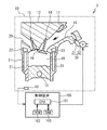
- FIG. 1 is a schematic diagram of an internal combustion engine system including a control device and an internal combustion engine according to a first embodiment.
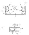
- FIG. 2A is an enlarged view of the vicinity of the ceiling of the combustion chamber of the internal combustion engine.
- FIG. 2B is a block diagram illustrating functions of a control device that controls the EGR device.
- FIG. 3A to FIG. 3C are diagrams for explaining control of the EGR device by the control device according to the first embodiment.
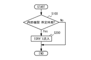
- FIG. 4 is a diagram illustrating an example of a flowchart when the control device according to the first embodiment controls the EGR device.
- FIG. 5 is a diagram illustrating an example of a flowchart when the control device according to the first modification of the first embodiment controls the EGR device.
- FIG. 1 is a schematic diagram of an internal combustion engine system including a control device and an internal combustion engine according to a first embodiment.
- FIG. 2A is an enlarged view of the vicinity of the ceiling of the combustion chamber of the internal combustion engine.
- FIG. 2B
- FIG. 6 is a schematic diagram of an internal combustion engine system including a control device and an internal combustion engine according to the second embodiment.
- FIG. 7A is a diagram showing the tip position of the tumble flow and the tip position of the EGR gas in the combustion chamber when the rotational speed (T R ) of the tumble flow is 0.8.
- FIG. 7B is a diagram showing the tip position of the tumble flow and the tip position of the EGR gas in the combustion chamber when the rotational speed (T R ) of the tumble flow is 1.7.
- FIGS. 8A to 8J are diagrams for explaining the control results of the control device when the tumble flow rotation speed is 0.8.
- 9 (a) to 9 (l) are diagrams for explaining the control results of the control device when the tumble flow rotation speed is 1.7.
- FIG. 7A is a diagram showing the tip position of the tumble flow and the tip position of the EGR gas in the combustion chamber when the rotational speed (T R ) of the tumble flow is 0.8.
- FIGS. 8A to 8J are diagram
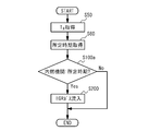
- FIG. 10 is a diagram illustrating an example of a flowchart when the control device according to the second embodiment controls the EGR device.
- FIG. 11 is a diagram illustrating an example of a flowchart when the control device according to the first modification of the second embodiment controls the EGR device.
- FIG. 1 is a schematic diagram of an internal combustion engine system 5 including a control device 100 and an internal combustion engine 10 according to the present embodiment.
- the internal combustion engine 10 includes a cylinder block 11, a cylinder head 12, a piston 13, an intake valve 14, an exhaust valve 15, an ignition plug 16, an injector 17, an EGR (Exhaust Gas Recirculation) device 30, and a crank position sensor 40.
- EGR exhaust Gas Recirculation
- the cylinder head 12 is disposed above the cylinder block 11.
- the piston 13 is disposed in the cylinder of the cylinder block 11.
- the piston 13 is connected to the crankshaft of the internal combustion engine 10 via a connecting rod. As the piston 13 moves up and down in the cylinder, the crankshaft rotates.
- a combustion chamber 18 is formed in a region surrounded by the cylinder block 11, the cylinder head 12, and the piston 13.
- the combustion chamber 18 is a space for burning an air-fuel mixture in which fuel and air are mixed.
- the upper and lower parts do not necessarily need to coincide with the upper and lower parts in the direction of gravity.
- the upper and lower sides in the present embodiment may be in the horizontal direction.
- the cylinder head 12 is formed with an intake passage 19 for guiding intake air to the combustion chamber 18 and an exhaust passage 20 for discharging exhaust gas from the combustion chamber 18.
- the intake valve 14 is a valve that opens and closes the intake passage 19.
- the exhaust valve 15 is a valve that opens and closes the exhaust passage 20.
- the spark plug 16 is a device for igniting a spark. That is, the internal combustion engine 10 is a spark ignition type internal combustion engine. In the present embodiment, the spark plug 16 is disposed in the center of the combustion chamber 18. However, the location of the spark plug 16 is not limited to this.
- the injector 17 is a device that injects fuel.
- the injector 17 is disposed in the intake passage 19.
- the arrangement location of the injector 17 is not limited to this.
- the injector 17 may be arranged in the internal combustion engine 10 so as to spray the fuel directly into the combustion chamber 18. That is, the internal combustion engine 10 may be an in-cylinder fuel injection internal combustion engine.
- the cylinder block 11 is formed with a cooling medium passage 21 through which the cooling medium passes.
- a cooling medium passage 22 through which the cooling medium passes is formed in the cylinder head 12. As the cooling medium passes through the cooling medium passage 21, the cylinder block 11 is cooled by the cooling medium. As the cooling medium passes through the cooling medium passage 22, the cylinder head 12 is cooled by the cooling medium.
- the EGR device 30 is a device that recirculates a part of the exhaust discharged from the combustion chamber 18 to the combustion chamber 18.
- the configuration of the EGR device 30 is not particularly limited.
- the EGR device 30 according to the present embodiment includes an EGR passage 31 and an EGR valve 32 as an example.
- the EGR passage 31 communicates the exhaust flow direction downstream side of the exhaust passage 20 with respect to the exhaust passage 20 and the intake passage 19 upstream of the intake valve 14 with respect to the intake flow direction.
- the EGR valve 32 is disposed in the EGR passage 31.
- the EGR valve 32 is controlled by the control device 100 to open and close the EGR passage 31.
- the EGR valve 32 opens the EGR passage 31 while the intake valve 14 opens the intake passage 19 in the intake stroke, a part of the exhaust gas existing in the exhaust passage 20 passes through the EGR passage 31 and the intake passage 19. And flows into the combustion chamber 18.
- EGR gas the gas that passes through the EGR passage 31 and flows into the combustion chamber 18 is referred to as EGR gas. That is, in the present embodiment, the EGR gas is a gas containing exhaust gas, and the EGR device 30 is a device that causes the EGR gas to flow into the combustion chamber 18.
- the crank position sensor 40 detects the position of the crankshaft of the internal combustion engine 10 and transmits the detection result to the control device 100.
- the control device 100 acquires the crank angle of the internal combustion engine 10 based on the detection result of the crank position sensor 40. That is, the crank position sensor 40 functions as a sensor that detects the crank angle of the internal combustion engine 10.
- the index indicating the operation state of the internal combustion engine 10 such as each stroke such as the intake stroke, the compression stroke, the fuel injection timing, the ignition timing, the position of the intake valve 14 and the exhaust valve 15 and the position of the piston 13 of the internal combustion engine 10 is a crank.
- the corner is the reference unit. Therefore, the control device 100 can acquire the operating state of the internal combustion engine 10 by acquiring the crank angle.
- an electronic control unit (Electronic Control Unit) can be used.
- an electronic control device including a CPU (Central Processing Unit) 101, a ROM (Read Only Memory) 102, and a RAM (Random Access Memory) 103 is used as an example of the control device 100.
- the control device 100 controls the fuel injection timing, ignition timing, and the like of the internal combustion engine 10 based on the detection result of the crank position sensor 40, and also controls the EGR device 30.
- FIG. 2 (a) is an enlarged view of the vicinity of the ceiling of the combustion chamber 18 of the internal combustion engine 10.
- illustration of the ignition plug 16 is abbreviate
- the internal combustion engine 10 has a structure in which generation of cooling loss in the cylinder head 12 is suppressed by heat insulation of the cylinder head 12.
- a structure having a heat insulating member 23 is used as an example of this structure.
- the heat insulating member 23 is disposed in a portion of the cylinder head 12 facing the combustion chamber 18. Specifically, the heat insulating member 23 is disposed on the ceiling surface portion of the combustion chamber 18 in the cylinder head 12.
- the heat insulating member 23 for example, a member having a lower thermal conductivity than the metal that is a material constituting the cylinder head 12 can be used.
- the heat insulating member 23 is disposed in the combustion chamber 18, whereby the cylinder head 12 can be insulated from the combustion chamber 18 by the heat insulating member 23. Thereby, generation
- the cooling of the cylinder block 11 is ensured by the cooling medium in the cooling medium passage 21. Therefore, the internal combustion engine 10 has a structure in which the cooling of the cylinder head 12 is suppressed by the heat insulation of the cylinder head 12 while ensuring the cooling of the cylinder block 11.
- FIG. 2B illustrates the functions of the control device 100 that controls the EGR device 30 in blocks.
- the function of the control device 100 that controls the EGR device 30 can be realized by the control unit 104 and the storage unit 105.
- the control unit 104 has a function of controlling the EGR device 30. Specifically, the control unit 104 has a function of controlling the EGR valve 32 of the EGR device 30.
- the storage unit 105 has a function of storing data necessary for the control of the control unit 104.
- the function of the control unit 104 is executed by the CPU 101, and the function of the storage unit 105 is executed by the ROM 102 and the RAM 103.
- the hardware that executes the function of the control unit 104 is not limited to the CPU 101, and the hardware that executes the function of the storage unit 105 is not limited to the ROM 102 and the RAM 103.
- the control unit 104 controls the EGR device 30 so that the EGR gas flows into the combustion chamber 18 at a predetermined time in the intake stroke of the internal combustion engine 10.
- the predetermined time is a time when EGR gas that has flowed into the combustion chamber 18 at a predetermined time in the intake stroke is located between the piston 13 and the air-fuel mixture when the piston 13 is at the top dead center in the compression stroke.
- the specific acquisition method of the predetermined time by the control part 104 is not specifically limited, The control part 104 which concerns on a present Example, as an example, the EGR gas which flowed into the combustion chamber 18 in the intake stroke is in an intake stroke.
- the time when it is placed on the top surface of the piston 13 is defined as a predetermined time.
- the timing when the EGR gas that has flowed into the combustion chamber 18 is placed on the top surface of the piston 13 during the intake stroke is specifically at the beginning of the intake stroke, more specifically, near the top dead center of the piston 13 during the intake stroke.
- the time of position can be used.
- the vicinity of the top dead center in the intake stroke means that the piston 13 includes a range where the piston 13 is lowered from the top dead center to a predetermined distance.
- the predetermined range is not particularly limited as long as the EGR gas that has flowed into the combustion chamber 18 is within a range where the EGR gas is placed on the top surface of the piston 13 in the intake stroke.
- the storage unit 105 stores the predetermined time in association with the crank angle.
- the control unit 104 acquires the crank angle based on the detection result of the crank position sensor 40, and EGR gas flows into the combustion chamber 18 when the acquired crank angle coincides with a predetermined time in the storage unit 105.
- the valve 32 is controlled.
- FIG. 3A to FIG. 3C are diagrams for explaining the control of the EGR device 30 by the control device 100.
- FIG. 3A shows the internal combustion engine 10 when the piston 13 is at top dead center (TDC) in the intake stroke.
- FIG. 3B shows the internal combustion engine 10 when the piston 13 is at bottom dead center (BDC) in the intake stroke.
- FIG. 3C shows the internal combustion engine 10 when the piston is at top dead center (TDC) in the compression stroke.
- the control unit 104 determines that the piston 13, which is an example of the timing when the EGR gas 200 flowing into the combustion chamber 18 is placed on the top surface of the piston 13 in the intake stroke, is near the top dead center.
- the EGR valve 32 is controlled so that the flow of the EGR gas 200 into the combustion chamber 18 starts at the timing.
- the control unit 104 controls the EGR valve 32 so that the inflow of the EGR gas 200 into the combustion chamber 18 is stopped after a predetermined period has elapsed since the inflow of the EGR gas 200 into the combustion chamber 18 was started. Note that the storage unit 105 stores the predetermined period. After the flow of the EGR valve 32 into the combustion chamber 18 stops, the air-fuel mixture 201 flows into the combustion chamber 18.
- the control unit 104 starts the inflow of the EGR gas 200 into the combustion chamber 18 when the piston 13 is near the top dead center in the intake stroke, and the inflow of the EGR gas 200 into the combustion chamber 18 in the intake stroke.
- the EGR device 30 is controlled so that the air-fuel mixture 201 starts to flow into the combustion chamber 18 after the engine stops.
- the EGR gas 200 is disposed on the top surface of the piston 13 and mixed on the EGR gas 200.
- Qi 201 is arranged.
- the EGR gas 200 flows into the combustion chamber 18 at a predetermined time in the intake stroke (when the EGR gas 200 that has flowed into the combustion chamber 18 is placed on the top surface of the piston 13 in the intake stroke).
- the EGR gas 200 that flows into the combustion chamber 18 in the intake stroke and rests on the top surface of the piston 13 also rests on the top surface of the piston 13 in the compression stroke.
- the EGR gas 200 can be positioned between the piston 13 and the air-fuel mixture 201 when is at the top dead center.
- FIG. 4 is a diagram illustrating an example of a flowchart when the control device 100 controls the EGR device 30.
- the control device 100 repeatedly executes the flowchart of FIG. 4 at a predetermined cycle.
- the control unit 104 of the control device 100 determines whether or not the internal combustion engine 10 is at a predetermined time in the intake stroke (step S100). Specifically, the control unit 104 acquires a crank angle based on the detection result of the crank position sensor 40, and determines whether or not the acquired crank angle matches a predetermined time stored in the storage unit 105. Thus, it is determined whether or not the internal combustion engine 10 is at a predetermined time in the intake stroke.
- step S100 When it is determined in step S100 that the internal combustion engine 10 is at the predetermined time in the intake stroke, the control unit 104 controls the EGR valve 32 so that the EGR gas 200 flows into the combustion chamber 18 for a predetermined period (step S200). Next, the control unit 104 ends the execution of the flowchart. If it is not determined in step S100 that the internal combustion engine 10 is at the predetermined time in the intake stroke, the control unit 104 ends the execution of the flowchart.
- the EGR device 30 is controlled so that the EGR gas 200 flows into the combustion chamber 18 at a predetermined time in the intake stroke.
- the inflowing EGR gas 200 can be positioned between the piston 13 and the air-fuel mixture 201 when the piston 13 is at the top dead center in the compression stroke.
- the flame generated when the air-fuel mixture 201 burns in the combustion chamber 18 and the piston 13 can be insulated by the EGR gas 200.
- the piston 13 is thermally insulated from the combustion chamber 18 by the EGR gas 200, so that the occurrence of cooling loss in the piston 13 can be suppressed.
- the piston 13 is thermally insulated from the combustion chamber 18 by the EGR gas 200, it is possible to suppress the occurrence of cooling loss in the cylinder block 11 disposed around the piston 13.
- the control device 100 it is possible to reduce the cooling loss in the internal combustion engine 10 having a structure in which the generation of the cooling loss in the cylinder head 12 is suppressed by the heat insulation of the cylinder head 12. As a result, the fuel efficiency of the internal combustion engine 10 can be improved.
- the control unit 104 of the control device 100 determines whether or not the operation state of the internal combustion engine 10 is an operation state in which knocking does not occur (hereinafter referred to as a non-knock operation state), and the operation state of the internal combustion engine 10 is non-knocking.
- the EGR device 30 may be controlled so that the EGR gas 200 flows into the combustion chamber 18 when it is determined to be in the operating state.
- a specific method for determining whether or not the operating state of the internal combustion engine 10 is the non-knocking operating state is not particularly limited.
- the control unit 104 according to the present modification determines whether or not the operation state of the internal combustion engine 10 is a non-knocking operation state based on the load of the internal combustion engine 10.
- the control unit 104 determines that the operation state of the internal combustion engine 10 is a non-knocking operation state when the load of the internal combustion engine 10 is a low load that is smaller than a predetermined load, and the internal combustion engine 10 When the load is a high load that is equal to or higher than a predetermined load, it is determined that the operating state of the internal combustion engine 10 is not the non-knocking operating state.
- the storage unit 105 stores the predetermined load, and the control unit 104 refers to the predetermined load in the storage unit 105 to determine whether or not the operating state of the internal combustion engine 10 is a non-knocking operation state.
- the load of the internal combustion engine 10 is acquired using, for example, the accelerator opening of the vehicle on which the internal combustion engine 10 is mounted, the amount of fuel injected from the injector 17, the amount of air sucked into the internal combustion engine 10, the rotational speed of the internal combustion engine 10, and the like. can do.
- FIG. 5 is a diagram illustrating an example of a flowchart when the control device 100 according to this modification controls the EGR device 30.
- the control device 100 repeatedly executes the flowchart of FIG. 5 at a predetermined cycle.
- the flowchart of FIG. 5 differs from the flowchart of FIG. 4 in that step S10 is executed before step S100.
- step S10 the control unit 104 determines whether the operation state of the internal combustion engine 10 is a non-knocking operation state based on the load of the internal combustion engine 10.
- the control unit 104 executes step S100.
- Step S ⁇ b> 100 and step S ⁇ b> 200 executed when an affirmative determination is made in step S ⁇ b> 100 are the same as the flowchart of FIG. If it is not determined in step S10 that the operation state of the internal combustion engine 10 is the non-knocking operation state, the control unit 104 ends the execution of the flowchart.
- the EGR gas 200 flows into the combustion chamber 18 when the operation state of the internal combustion engine 10 is the non-knocking operation state. Even if the temperature of the combustion chamber 18 rises as a result of being insulated from the combustion chamber 18, it is possible to prevent knocking from occurring in the internal combustion engine 10.
- the non-knocking operation state is not limited to a case where the load of the internal combustion engine 10 is a low load state.
- the internal combustion engine 10 includes a supercharger
- knocking does not occur even when supercharging is performed by the supercharger. Therefore, when the internal combustion engine 10 includes a supercharger as described above, a state in which supercharging by the supercharger is performed can be used as the non-knocking operation state.
- FIG. 6 is a schematic diagram of an internal combustion engine system 5a including the control device 100a and the internal combustion engine 10a according to the present embodiment.
- the internal combustion engine 10a is different from the internal combustion engine 10 according to the first embodiment in that it has a structure in which a swirling airflow is generated in the combustion chamber 18 in the intake stroke. Since the other structure of the internal combustion engine 10a is the same as that of the internal combustion engine 10 according to the first embodiment, the description thereof is omitted.
- the internal combustion engine 10a has a structure including an airflow control valve 24 as an example of a structure in which a swirling airflow is generated in the combustion chamber 18 in the intake stroke.
- the airflow control valve 24 is a valve that controls the flow direction of the airflow flowing into the combustion chamber 18.
- a tumble control valve, a swirl control valve, or the like can be used as the airflow control valve 24.
- a tumble control valve is generated as the swirling airflow. Therefore, a tumble control valve is used as the airflow control valve 24.
- the structure in which the swirling airflow is generated in the combustion chamber 18 in the intake stroke is not limited to the structure provided with the airflow control valve 24.
- a swirling airflow can be formed in the combustion chamber 18 during the intake stroke by appropriately setting the shape of the intake passage 19. Therefore, the internal combustion engine 10a swirls into the combustion chamber 18 in the intake stroke in place of the structure including the air flow control valve 24 or together with the structure including the air flow control valve 24 as a structure in which the swirling air flow is generated in the combustion chamber 18 in the intake stroke.
- the control device 100a is different from the control device 100 according to the first embodiment in that a control unit 104a is provided instead of the control unit 104.
- the control unit 104a is configured to control the airflow control valve 24 so that a tumble flow is generated in the combustion chamber 18 in the intake stroke, and to control the EGR device 30 based on the rotational speed of the tumble flow.
- 1 is different from the control unit 104 according to 1.
- the rotational speed of the tumble flow refers to the rotational speed of the tumble flow per predetermined period of the internal combustion engine 10a.
- the rotational speed of the tumble flow according to the present embodiment is the rotational speed of the tumble flow per cycle of the internal combustion engine 10a.
- the rotational speed of the tumble flow is one index indicating the strength of the tumble flow.
- the specific control method of the airflow control valve 24 by the control unit 104a is not particularly limited.
- the control part 104a which concerns on a present Example controls the airflow control valve 24 according to the load of the internal combustion engine 10a as an example.
- the storage unit 105 stores a map in which the opening degree of the airflow control valve 24 is defined in association with the load of the internal combustion engine 10a.
- the control unit 104a acquires the opening degree of the airflow control valve 24 corresponding to the load of the internal combustion engine 10a from the map, and controls the airflow control valve 24 so that the acquired opening degree is obtained.
- the control unit 104a controls the air flow control valve 24 according to the load of the internal combustion engine 10a, so that a tumble flow having an appropriate rotation speed with respect to the load of the internal combustion engine 10a can be generated in the combustion chamber 18. it can.
- the storage unit 105 is configured so that the EGR gas that has flowed into the combustion chamber 18 in the intake stroke moves on the tumble flow and moves through the combustion chamber 18, and the piston 13 is at the top dead center in the compression stroke.
- a map is stored that defines a plurality of timings of inflow of EGR gas into the combustion chamber 18 during the intake stroke as placed on the top surface of the engine 13 in association with the rotational speed of the tumble flow.
- the control unit 104a acquires the rotation speed of the tumble flow, acquires the inflow timing of the EGR gas into the combustion chamber 18 corresponding to the acquired rotation speed of the tumble flow from the storage unit 105, and sets the acquired inflow timing to a predetermined value.
- the EGR valve 32 is controlled so that the EGR gas flows into the combustion chamber 18 at this predetermined timing.
- the acquisition method of the rotation speed of the tumble flow by the control unit 104a is not particularly limited.
- the control unit 104a can acquire the rotational speed of the tumble flow based on a sensor that detects the rotational speed of the tumble flow, a parameter having a correlation with the rotational speed of the tumble flow, and the like.
- the rotational speed of the tumble flow has a correlation with the opening degree of the airflow control valve 24. Therefore, the control unit 104a can acquire the rotational speed of the tumble flow based on the opening degree of the airflow control valve 24.
- the storage unit 105 stores a map in which the rotational speed of the tumble flow is defined in association with the opening degree of the airflow control valve 24, and the control unit 104a stores the tumble flow corresponding to the opening degree of the airflow control valve 24.
- the rotation number of the tumble flow can be acquired by acquiring the rotation number of the tumble flow from the map of the storage unit 105.
- the rotational speed of the tumble flow has a correlation with the flow velocity of the intake air flowing into the combustion chamber 18. Therefore, for example, when the structure in which the tumble flow is generated in the combustion chamber 18 does not include the air flow control valve 24, the control unit 104a determines the rotation speed of the tumble flow based on the flow velocity of the intake air flowing into the combustion chamber 18. You may get it.
- the flow velocity of the intake air flowing into the combustion chamber 18 can be acquired based on the detection result of a sensor such as an air flow meter.
- the map stored in the storage unit 105 (a map in which a plurality of inflow timings of the EGR gas into the combustion chamber 18 in the intake stroke are associated with the rotational speed of the tumble flow) is an example of data.
- the rotational speed of the tumble flow is 0.8
- the inflow timing of the EGR gas into the combustion chamber 18 in the intake stroke is defined as 130 °.
- the map defines that the time when the EGR gas flows into the combustion chamber 18 in the intake stroke is 40 ° when the rotational speed of the tumble flow is 1.7.
- FIG. 7A is a diagram showing the tip position of the tumble flow and the tip position of the EGR gas in the combustion chamber 18 when the tumble flow rotation speed (T R ) is 0.8.
- FIG. 7B is a diagram showing the tip position of the tumble flow and the tip position of the EGR gas in the combustion chamber 18 when the rotational speed (T R ) of the tumble flow is 1.7.
- the upper side indicates the cylinder head 12 side of the combustion chamber 18, and the lower side indicates the piston 13 side of the combustion chamber 18.
- the horizontal axis is the crank angle.
- crank angle 0 ° is the crank angle when the piston 13 is at the top dead center in the intake stroke
- crank angle 360 ° is the crank angle when the piston 13 is at the top dead center in the compression stroke.
- the control unit 104a determines the inflow timing (crank angle 130 °) of the EGR gas into the combustion chamber 18 in the intake stroke corresponding to the rotational speed 0.8 of the tumble flow.
- the EGR device 30 is controlled so that EGR gas flows from the storage unit 105 and flows into the combustion chamber 18 at the acquired crank angle of 130 °.
- the control unit 104a determines the inflow timing (crank angle 40 °) of the EGR gas into the combustion chamber 18 in the intake stroke corresponding to the rotational speed 1.7 of the tumble flow.
- the EGR device 30 is controlled so that the EGR gas is acquired from the storage unit 105 and flows into the combustion chamber 18 at the acquired crank angle of 40 °. As a result, the EGR gas that has flowed into the combustion chamber 18 moves in the combustion chamber 18 as shown in FIG.
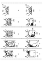
- FIGS. 8 (a) to 8 (j) are diagrams for explaining the control results of the control device 100a when the tumble flow speed is 0.8.
- FIGS. 8A to 8E schematically show the flow states of gases other than the EGR gas 200.
- FIG. 8 (f) to 8 (j) schematically show the flow states of the EGR gas 200 and the tumble flow 202.
- FIG. The crank angle in FIGS. 8 (a) and 8 (f) is 130 °
- the crank angle in FIGS. 8 (b) and 8 (g) is 180 °
- FIGS. 8 (c) and 8 (h) ) Is 240 °
- the crank angle in FIGS. 8 (d) and 8 (i) is 300 °
- the crank angle in FIGS. 8 (e) and 8 (j) is 360 °.
- the EGR gas 200 flowing into the combustion chamber 18 at a crank angle of 130 ° moves on the tumble flow 202 and moves through the combustion chamber 18 so that the piston 13 moves in the compression stroke. It is on the top surface of the piston 13 when it is at the top dead center (when the crank angle is 360 °).
- an air-fuel mixture is disposed above the EGR gas 200. Therefore, the EGR gas 200 is located between the piston 13 and the air-fuel mixture when the piston 13 is at the top dead center in the compression stroke.
- FIGS. 9 (a) to 9 (l) are diagrams for explaining the control results of the control device 100a when the tumble flow speed is 1.7.
- FIGS. 9A to 9F schematically show the flow states of gases other than the EGR gas 200.
- FIG. 9 (g) to 9 (l) schematically show the flow states of the EGR gas 200 and the tumble flow 202.
- FIG. The crank angle in FIGS. 9 (a) and 9 (g) is 40 °
- the crank angle in FIGS. 9 (b) and 9 (h) is 120 °
- FIGS. 9 (c) and 9 (i). ) Is 180 °
- the crank angle in FIGS. 9 (d) and 9 (j) is 240 °
- the crank angle in FIGS. 9 (e) and 9 (k) is 300 °
- the crank angle in FIGS. 9 (f) and 9 (l) is 360 °.
- the EGR gas 200 flowing into the combustion chamber 18 at a crank angle of 40 ° moves on the tumble flow 202 and moves through the combustion chamber 18, and the piston 13 moves in the compression stroke. It is on the top surface of the piston 13 when it is at the top dead center (when the crank angle is 360 °).
- an air-fuel mixture is disposed above the EGR gas 200. Therefore, the EGR gas 200 is located between the piston 13 and the air-fuel mixture when the piston 13 is at the top dead center in the compression stroke.
- FIG. 10 is a diagram illustrating an example of a flowchart when the control device 100 a controls the EGR device 30.
- the control device 100a repeatedly executes the flowchart of FIG. 10 at a predetermined cycle.
- the control unit 104a of the control device 100a acquires the rotation speed (T R ) of the tumble flow 202 (step S50).
- the control unit 104a acquires a predetermined time based on the rotational speed of the tumble flow 202 acquired in step S50 (step S60).
- the control unit 104a acquires the inflow timing of the EGR gas into the combustion chamber 18 corresponding to the rotation speed of the tumble flow 202 acquired in step S50 from the storage unit 105, and the acquired inflow timing is a predetermined time.
- step S100a determines whether or not the internal combustion engine 10 is at the predetermined time acquired in step S60 (step S100a). Specifically, in step S100a, the control unit 104a acquires the crank angle based on the detection result of the crank position sensor 40, and determines whether or not the acquired crank angle matches the predetermined time acquired in step S60. By determining, it is determined whether or not the internal combustion engine 10 is at the predetermined time acquired in step S60.
- step S200 is the same as step S200 in FIG. If it is not determined in step S100a that the internal combustion engine 10 is at the predetermined time acquired in step S60, the control unit 104a ends the execution of the flowchart.
- the control unit 104a controls the EGR device 30 based on the rotational speed of the tumble flow. Specifically, the control unit 104a acquires the rotation speed of the tumble flow 202, acquires the inflow timing of the EGR gas 200 into the combustion chamber 18 corresponding to the acquired rotation speed of the tumble flow 202 from the storage unit 105, The EGR device 30 is controlled so that the EGR gas 200 flows into the combustion chamber 18 at the acquired inflow timing.
- the EGR gas 200 that has flowed into the combustion chamber 18 in the intake stroke is positioned between the piston 13 and the air-fuel mixture when the piston 13 is at the top dead center in the compression stroke.
- the flame generated when the air-fuel mixture burns in the combustion chamber 18 and the piston 13 can be insulated from each other by the EGR gas 200, so that the occurrence of cooling loss in the piston 13 can be suppressed.
- the piston 13 is thermally insulated from the combustion chamber 18 by the EGR gas 200, it is possible to suppress the occurrence of cooling loss in the cylinder block 11 disposed around the piston 13. Therefore, it is possible to reduce the cooling loss in the internal combustion engine 10 a having a structure in which the generation of the cooling loss in the cylinder head 12 is suppressed by the heat insulation of the cylinder head 12. As a result, the fuel consumption of the internal combustion engine 10a can be improved.
- the time when the EGR gas 200 flows into the combustion chamber 18 is not limited to the time when the EGR gas 200 that flows into the combustion chamber 18 rests on the top surface of the piston 13 in the intake stroke. As a result, it is possible to widen the selection range of the timing when the EGR gas 200 flows into the combustion chamber 18 in the intake stroke.
- the internal combustion engine 10a has a structure in which a tumble flow is generated in the combustion chamber 18 in the intake stroke, the combustion of the air-fuel mixture can be promoted by the tumble flow 202.
- the amount of heat released from the combustion chamber 18 to the cylinder block 11 increases.
- the amount of heat released from the combustion chamber 18 to the cylinder block 11 increases, the amount of heat released from the combustion chamber 18 to the cylinder head 12 decreases. Thereby, the cooling loss in the cylinder head 12 can be reduced.
- the tumble flow 202 faces the combustion chamber 18 of the cylinder block 11 as shown in FIGS. 8B and 9B, for example. By hitting the wall surface, the wall surface facing the combustion chamber 18 of the cylinder block 11 can be cooled by the tumble flow 202. Thereby, an increase in cooling loss in the cylinder block 11 is suppressed.
- the control unit 104a determines whether or not the operation state of the internal combustion engine 10a is a non-knocking operation state, and the operation state of the internal combustion engine 10a.
- the EGR device 30 may be controlled so that the EGR gas 200 flows into the combustion chamber 18 when it is determined that the engine is in the non-knocking operation state.
- the non-knocking operation state for example, a state where the load of the internal combustion engine 10 is low, a state where supercharging by the supercharger is performed, and the like can be used as in the case of the first modification of the first embodiment. .
- FIG. 11 is a diagram illustrating an example of a flowchart when the control device 100a according to the present modification controls the EGR device 30.
- the control device 100a according to the present modification repeatedly executes the flowchart of FIG. 11 at a predetermined cycle.
- the flowchart of FIG. 11 differs from the flowchart of FIG. 10 in that step S10 is executed before step S50.
- the control unit 104a determines whether or not the operation state of the internal combustion engine 10a is a non-knocking operation state. Since step S10 in FIG. 11 is the same as step S10 in FIG. 5, detailed description thereof is omitted.
- step S50 When it is determined in step S10 of FIG. 11 that the operating state of the internal combustion engine 10a is the non-knocking operating state, the control unit 104a executes step S50.
- Step S50, step S60, step S100a, and step S200 are the same as step S50, step S60, step S100a, and step S200 in FIG. If it is not determined in step S10 in FIG. 11 that the operation state of the internal combustion engine 10a is the non-knocking operation state, the control unit 104a ends the execution of the flowchart.
- the EGR gas 200 flows into the combustion chamber 18 when the operation state of the internal combustion engine 10a is in the non-knocking operation state. Even if the temperature of the combustion chamber 18 rises by being insulated from the chamber 18, it is possible to prevent knocking from occurring in the internal combustion engine 10a.
Landscapes
- Engineering & Computer Science (AREA)
- Chemical & Material Sciences (AREA)
- Combustion & Propulsion (AREA)
- Mechanical Engineering (AREA)
- General Engineering & Computer Science (AREA)
- Output Control And Ontrol Of Special Type Engine (AREA)
- Combustion Methods Of Internal-Combustion Engines (AREA)
- Combined Controls Of Internal Combustion Engines (AREA)
Abstract
内燃機関10の制御装置100は、燃焼室18と、シリンダヘッド12における冷却損失の発生がシリンダヘッドの断熱によって抑制された構造と、燃焼室から排出された排気の一部を含んだガスであるEGRガス200を燃焼室に流入させるEGR装置30と、を備える内燃機関の吸気行程における所定時期にEGRガスが燃焼室へ流入するようにEGR装置を制御する制御部104を備え、所定時期は、所定時期に燃焼室に流入したEGRガスが内燃機関の圧縮行程においてピストン13が上死点にあるときにピストンと混合気201との間に位置する時期である。
Description
本発明は、内燃機関の制御装置に関する。
従来、内燃機関の正味仕事に用いられない損失として、ポンプ損失、排気損失、冷却損失、機械損失等がある。これらの損失のうち冷却損失は大きなウエイトを占めることから、冷却損失の発生を抑制して燃費向上を図るための技術が考案されている。例えば特許文献1には、内燃機関のシリンダヘッドに断熱部材を配置することでシリンダヘッドを燃焼室から断熱した技術が開示されている。この技術によれば、シリンダヘッドにおける冷却損失の発生を抑制することができる。
特許文献1に係る技術では、シリンダヘッドにおける冷却損失の発生が抑制された分、内燃機関の冷却損失が低減している。しかしながら、内燃機関における燃費向上のためには、内燃機関の冷却損失をさらに低減させることが望まれる。
本発明は、シリンダヘッドにおける冷却損失の発生がシリンダヘッドの断熱によって抑制された構造を有する内燃機関における冷却損失の低減を図ることができる内燃機関の制御装置を提供することを目的とする。
本発明に係る内燃機関の制御装置は、ピストンとシリンダブロックとシリンダヘッドとによって区画され、燃料と空気とが混合した混合気が燃焼するための燃焼室と、前記シリンダヘッドにおける冷却損失の発生が前記シリンダヘッドの断熱によって抑制された構造と、前記燃焼室から排出された排気の一部を含んだガスであるEGRガスを前記燃焼室に流入させるEGR装置と、を備える内燃機関の吸気行程における所定時期に前記EGRガスが前記燃焼室へ流入するように前記EGR装置を制御する制御部を備え、前記所定時期は、前記所定時期に前記燃焼室に流入した前記EGRガスが前記内燃機関の圧縮行程において前記ピストンが上死点にあるときに前記ピストンと前記混合気との間に位置する時期である。
本発明に係る内燃機関の制御装置よれば、圧縮行程においてピストンが上死点にあるときにピストンと混合気との間にEGRガスを位置させることができる。この場合、燃焼室において発生する火炎とピストンとをEGRガスによって断熱することができる。このようにピストンがEGRガスによって燃焼室から断熱されることで、ピストンにおける冷却損失の発生を抑制することができる。また、ピストンがEGRガスによって燃焼室から断熱されることで、ピストンの周囲に配置されているシリンダブロックにおける冷却損失の発生も抑制することができる。以上のように本発明に係る内燃機関の制御装置によれば、シリンダヘッドにおける冷却損失の発生がシリンダヘッドの断熱によって抑制された構造を有する内燃機関における冷却損失の低減を図ることができる。
上記構成において、前記制御部は、前記吸気行程において前記燃焼室に流入した前記EGRガスが前記吸気行程において前記ピストンの頂面に載る時期を前記所定時期としてもよい。この構成によれば、吸気行程において燃焼室に流入してピストンの頂面に載ったEGRガスは圧縮行程においてもピストンの頂面に載り、その結果、圧縮行程においてピストンが上死点にあるときにEGRガスをピストンと混合気との間に位置させることができる。
上記構成において、前記内燃機関は、前記吸気行程において前記燃焼室にタンブル流が生成される構造を有していてもよい。この構成によれば、タンブル流によって混合気の燃焼を促進させることができる。その結果、燃焼室からシリンダブロックへの放熱量が増加する。燃焼室からシリンダブロックへの放熱量が増加する分、燃焼室からシリンダヘッドへの放熱量は低減する。それにより、シリンダヘッドにおける冷却損失の低減を図ることができる。一方、燃焼室からシリンダブロックへの放熱量が増加しても、タンブル流によってシリンダブロックの燃焼室に面した壁面を冷却することができる。それによりシリンダブロックにおける冷却損失の増加を抑制することができる。
上記構成は、前記吸気行程において前記燃焼室に流入した前記EGRガスが前記タンブル流に乗って前記燃焼室を移動して前記圧縮行程において前記ピストンが前記上死点にあるときに前記ピストンの頂面に載るような前記吸気行程における前記EGRガスの前記燃焼室への流入時期を、前記タンブル流の回転数に関連付けて複数規定したマップを記憶する記憶部をさらに備え、前記制御部は、前記タンブル流の回転数を取得し、取得された前記タンブル流の回転数に対応する前記流入時期を前記記憶部から取得し、取得された前記流入時期を前記所定時期としてもよい。
この構成によれば、吸気行程における所定時期に燃焼室に流入したEGRガスを圧縮行程においてピストンが上死点にあるときにピストンと混合気との間に位置させることができる。この場合、EGRガスを燃焼室に流入させる時期が、燃焼室に流入したEGRガスが吸気行程においてピストンの頂面に載る時期に限定されないことから、吸気行程においてEGRガスを燃焼室に流入させる時期の選択の幅を広くすることができる。
上記構成において、前記制御部は、前記内燃機関の運転状態がノッキングの発生しない運転状態の場合に前記EGRガスの前記燃焼室への流入が行なわれるように前記EGR装置を制御してもよい。この構成によれば、EGRガスによってピストンが燃焼室から断熱された結果、燃焼室の温度が上昇した場合であっても、内燃機関にノッキングが発生することを阻止することができる。上記構成において、前記制御部は、前記内燃機関の負荷に基づいて前記内燃機関の運転状態が前記ノッキングの発生しない運転状態であるか否かを判定してもよい。
本発明によれば、シリンダヘッドにおける冷却損失の発生がシリンダヘッドの断熱によって抑制された構造を有する内燃機関における冷却損失の低減を図ることができる内燃機関の制御装置を提供することができる。
以下、本発明を実施するための形態を説明する。
本発明の実施例1に係る内燃機関10の制御装置100(以下、制御装置100と略称する)について説明する。図1は、本実施例に係る制御装置100および内燃機関10を備える内燃機関システム5の模式図である。内燃機関10は、シリンダブロック11、シリンダヘッド12、ピストン13、吸気弁14、排気弁15、点火プラグ16、インジェクタ17、EGR(Exhaust Gas Recirculation)装置30およびクランクポジションセンサ40を備えている。
シリンダヘッド12は、シリンダブロック11の上方に配置されている。ピストン13は、シリンダブロック11の気筒内に配置されている。ピストン13は、内燃機関10のクランク軸にコンロッドを介して接続されている。ピストン13が気筒内を上下動することで、クランク軸は回転する。シリンダブロック11とシリンダヘッド12とピストン13とによって囲まれた領域に、燃焼室18が形成されている。燃焼室18は、燃料と空気とが混合した混合気が燃焼するための空間である。なお、本実施例において上方および下方は、必ずしも重力方向における上方および下方と一致している必要はない。例えば、本実施例における上方および下方は水平方向であってもよい。
シリンダヘッド12には、燃焼室18に吸気を導くための吸気通路19と燃焼室18から排気を排出するための排気通路20とが形成されている。吸気弁14は、吸気通路19を開閉する弁である。排気弁15は、排気通路20を開閉する弁である。点火プラグ16は、火花を点火するための装置である。すなわち、内燃機関10は火花点火式の内燃機関である。本実施例において点火プラグ16は、燃焼室18の中央に配置されている。但し、点火プラグ16の配置箇所はこれに限定されるものではない。
インジェクタ17は、燃料を噴射する装置である。本実施例においてインジェクタ17は、吸気通路19に配置されている。但し、インジェクタ17の配置箇所はこれに限定されるものではない。例えばインジェクタ17は、燃料を燃焼室18に直接噴霧するように内燃機関10に配置されていてもよい。すなわち、内燃機関10は筒内燃料噴射式の内燃機関であってもよい。
シリンダブロック11には、冷却媒体が通過するための冷却媒体通路21が形成されている。シリンダヘッド12には、冷却媒体が通過するための冷却媒体通路22が形成されている。冷却媒体が冷却媒体通路21を通過することで、シリンダブロック11は冷却媒体によって冷却される。冷却媒体が冷却媒体通路22を通過することで、シリンダヘッド12は冷却媒体によって冷却される。
EGR装置30は、燃焼室18から排出された排気の一部を燃焼室18に再循環させる装置である。EGR装置30の構成は特に限定されるものではない。本実施例に係るEGR装置30は、一例として、EGR通路31およびEGR弁32を備えている。
EGR通路31は、排気通路20の排気弁15よりも排気の流動方向下流側と、吸気通路19の吸気弁14よりも吸気の流動方向上流側とを連通している。EGR弁32は、EGR通路31に配置されている。EGR弁32は、制御装置100に制御されてEGR通路31を開閉する。吸気行程において吸気弁14が吸気通路19を開にした状態でEGR弁32がEGR通路31を開にした場合、排気通路20に存在する排気の一部はEGR通路31および吸気通路19を通過して燃焼室18に流入する。これ以降、EGR通路31を通過して燃焼室18に流入するガスをEGRガスと称する。すなわち、本実施例において、EGRガスは排気を含んだガスであり、EGR装置30はEGRガスを燃焼室18に流入させる装置である。
クランクポジションセンサ40は、内燃機関10のクランク軸の位置を検出し、検出結果を制御装置100に伝える。制御装置100は、クランクポジションセンサ40の検出結果に基づいて、内燃機関10のクランク角を取得する。すなわち、クランクポジションセンサ40は、内燃機関10のクランク角を検出するセンサとしての機能を有している。なお、内燃機関10の吸気行程、圧縮行程等の各行程、燃料噴射時期、点火時期、吸気弁14および排気弁15の位置、ピストン13の位置等の内燃機関10の運転状態を示す指標はクランク角を基準単位としている。したがって、制御装置100は、クランク角を取得することで、内燃機関10の運転状態を取得することができる。
制御装置100としては、電子制御装置(Electronic Control Unit)を用いることができる。本実施例においては、制御装置100の一例として、CPU(Central Processing Unit)101、ROM(Read Only Memory)102およびRAM(Random Access Memory)103を備える電子制御装置を用いる。制御装置100は、クランクポジションセンサ40の検出結果に基づいて内燃機関10の燃料噴射時期、点火時期等を制御するとともに、EGR装置30を制御する。
図2(a)は、内燃機関10の燃焼室18の天井部付近の拡大図である。なお、図2(a)において点火プラグ16の図示は省略されている。内燃機関10は、シリンダヘッド12における冷却損失の発生がシリンダヘッド12の断熱によって抑制された構造を有している。本実施例においては、この構造の一例として、断熱部材23を有する構造が用いられている。断熱部材23は、シリンダヘッド12の燃焼室18に面した部分に配置されている。具体的には、断熱部材23はシリンダヘッド12における燃焼室18の天井面の部分に配置されている。断熱部材23としては、例えば、シリンダヘッド12を構成する材料である金属よりも熱伝導率の小さい部材を用いることができる。
このように燃焼室18に断熱部材23が配置されていることで、断熱部材23によってシリンダヘッド12を燃焼室18から断熱することができる。それにより、シリンダヘッド12における冷却損失の発生を抑制することができる。その結果、内燃機関10の燃費を向上させることができる。なお、本実施例に係る内燃機関10において、シリンダブロック11の冷却は、冷却媒体通路21の冷却媒体によって確保されている。したがって、内燃機関10は、シリンダブロック11の冷却を確保しつつ、シリンダヘッド12における冷却損失の発生がシリンダヘッド12の断熱によって抑制された構造を有している。
続いて制御装置100によるEGR装置30の制御について説明する。図2(b)は、EGR装置30を制御する制御装置100の機能をブロックで図示したものである。EGR装置30を制御する制御装置100の機能は、制御部104および記憶部105によって実現することができる。
制御部104は、EGR装置30を制御する機能を有している。具体的には制御部104は、EGR装置30のEGR弁32を制御する機能を有している。記憶部105は、制御部104の制御に必要なデータ等を記憶する機能を有している。制御部104の機能はCPU101によって実行され、記憶部105の機能はROM102およびRAM103によって実行される。但し、制御部104の機能を実行するハードウエアはCPU101に限定されるものではなく、記憶部105の機能を実行するハードウエアはROM102およびRAM103に限定されるものではない。
制御部104は、内燃機関10の吸気行程における所定時期にEGRガスが燃焼室18へ流入するようにEGR装置30を制御する。ここで、所定時期は、吸気行程の所定時期に燃焼室18に流入したEGRガスが圧縮行程においてピストン13が上死点にある場合にピストン13と混合気との間に位置する時期である。
制御部104による所定時期の具体的な取得手法は特に限定されるものではないが、本実施例に係る制御部104は、一例として、吸気行程において燃焼室18に流入したEGRガスが吸気行程においてピストン13の頂面に載る時期を所定時期とする。なお、燃焼室18に流入したEGRガスが吸気行程においてピストン13の頂面に載る時期は、具体的には吸気行程の初期、より具体的にはピストン13が吸気行程における上死点の近傍に位置する時期を用いることができる。この吸気行程における上死点の近傍とは、ピストン13が上死点から所定距離まで下がった範囲を含むという意味である。この所定範囲は、燃焼室18に流入したEGRガスが吸気行程においてピストン13の頂面に載る範囲内であれば、特に限定されるものではない。
記憶部105は、所定時期をクランク角に関連付けて記憶しておく。制御部104は、クランクポジションセンサ40の検出結果に基づいてクランク角を取得し、取得されたクランク角が記憶部105の所定時期に合致した場合にEGRガスが燃焼室18に流入するようにEGR弁32を制御する。
制御装置100によるEGR装置30の制御の一例を、図を用いてさらに詳細に説明する。図3(a)~図3(c)は、制御装置100によるEGR装置30の制御を説明するための図である。図3(a)は、吸気行程においてピストン13が上死点(TDC)にある場合の内燃機関10を示している。図3(b)は、吸気行程においてピストン13が下死点(BDC)にある場合の内燃機関10を示している。図3(c)は、圧縮行程においてピストンが上死点(TDC)にある場合の内燃機関10を示している。
図3(a)に示すように、制御部104は、燃焼室18に流入したEGRガス200が吸気行程においてピストン13の頂面に載る時期の一例であるピストン13が上死点の近傍にある時期にEGRガス200の燃焼室18への流入が開始するように、EGR弁32を制御する。
制御部104は、EGRガス200の燃焼室18への流入が開始されてから所定期間経過後にEGRガス200の燃焼室18への流入が停止するように、EGR弁32を制御する。なお、所定期間は記憶部105が記憶しておく。EGR弁32の燃焼室18への流入が停止した後には、燃焼室18には混合気201が流入する。
このように制御部104は、吸気行程においてピストン13が上死点の近傍にある時期にEGRガス200の燃焼室18への流入が開始し、吸気行程においてEGRガス200の燃焼室18への流入が停止した後に混合気201の燃焼室18への流入が開始するように、EGR装置30を制御している。この制御が行われる結果、図3(b)に示すように、ピストン13が下死点にあるときにおいて、ピストン13の頂面の上にEGRガス200が配置され、EGRガス200の上に混合気201が配置されることになる。
図3(b)に示すEGRガス200および混合気201の配置形態は、圧縮行程中、維持される。その結果、図3(c)に示すように圧縮行程においてピストン13が上死点にあるとき、EGRガス200はピストン13と混合気201との間に位置する。この状態で点火プラグ16によって混合気201に火花が点火される。
以上のように制御部104が吸気行程における所定時期(燃焼室18に流入したEGRガス200が吸気行程においてピストン13の頂面に載る時期)にEGRガス200が燃焼室18へ流入するようにEGR装置30を制御することで、吸気行程において燃焼室18に流入してピストン13の頂面に載ったEGRガス200は圧縮行程においてもピストン13の頂面に載り、その結果、圧縮行程においてピストン13が上死点にあるときにEGRガス200をピストン13と混合気201との間に位置させることができる。それにより、圧縮行程においてピストン13が上死点にあるときの燃焼室18において、ピストン13側にEGRガス200が配置され、シリンダヘッド12側に混合気201が配置されたEGRガス200と混合気201との2層構造が得られる。
図4は、制御装置100がEGR装置30を制御するときのフローチャートの一例を示す図である。制御装置100は、図4のフローチャートを所定の周期で繰り返し実行する。まず制御装置100の制御部104は、内燃機関10が吸気行程における所定時期であるか否かを判定する(ステップS100)。具体的には制御部104は、クランクポジションセンサ40の検出結果に基づいてクランク角を取得し、取得されたクランク角が記憶部105に記憶された所定時期に合致するか否かを判定することで、内燃機関10が吸気行程における所定時期であるか否かを判定する。
ステップS100において内燃機関10が吸気行程における所定時期であると判定された場合、制御部104は、EGRガス200が燃焼室18に所定期間流入するようにEGR弁32を制御する(ステップS200)。次いで制御部104はフローチャートの実行を終了する。ステップS100において内燃機関10が吸気行程における所定時期であると判定されなかった場合、制御部104はフローチャートの実行を終了する。
以上のように本実施例に係る制御装置100によれば、吸気行程における所定時期にEGRガス200が燃焼室18へ流入するようにEGR装置30を制御することで、吸気行程において燃焼室18に流入したEGRガス200を圧縮行程においてピストン13が上死点にあるときにピストン13と混合気201との間に位置させることができる。この場合、燃焼室18において混合気201の燃焼時に発生する火炎とピストン13とをEGRガス200によって断熱することができる。このようにピストン13がEGRガス200によって燃焼室18から断熱されることで、ピストン13における冷却損失の発生を抑制することができる。また、ピストン13がEGRガス200によって燃焼室18から断熱されることで、ピストン13の周囲に配置されているシリンダブロック11における冷却損失の発生も抑制することができる。このように本実施例に係る制御装置100によれば、シリンダヘッド12における冷却損失の発生がシリンダヘッド12の断熱によって抑制された構造を有する内燃機関10における冷却損失の低減を図ることができる。その結果、内燃機関10の燃費を向上させることができる。
(変形例1)
制御装置100の制御部104は、内燃機関10の運転状態がノッキングの発生しない運転状態(以下、非ノッキング運転状態と称する)であるか否かを判定し、内燃機関10の運転状態が非ノッキング運転状態であると判定された場合にEGRガス200の燃焼室18への流入が行なわれるようにEGR装置30を制御してもよい。内燃機関10の運転状態が非ノッキング運転状態であるか否かの具体的な判定手法は、特に限定されるものではない。本変形例に係る制御部104は、一例として、内燃機関10の負荷に基づいて内燃機関10の運転状態が非ノッキング運転状態であるか否かを判定する。
制御装置100の制御部104は、内燃機関10の運転状態がノッキングの発生しない運転状態(以下、非ノッキング運転状態と称する)であるか否かを判定し、内燃機関10の運転状態が非ノッキング運転状態であると判定された場合にEGRガス200の燃焼室18への流入が行なわれるようにEGR装置30を制御してもよい。内燃機関10の運転状態が非ノッキング運転状態であるか否かの具体的な判定手法は、特に限定されるものではない。本変形例に係る制御部104は、一例として、内燃機関10の負荷に基づいて内燃機関10の運転状態が非ノッキング運転状態であるか否かを判定する。
具体的には制御部104は、内燃機関10の負荷が所定負荷よりも小さい負荷である低負荷の場合に、内燃機関10の運転状態が非ノッキング運転状態であると判定し、内燃機関10の負荷が所定負荷以上の負荷である高負荷の場合に、内燃機関10の運転状態が非ノッキング運転状態でないと判定する。所定負荷は記憶部105が記憶しておき、制御部104は記憶部105の所定負荷を参照することで内燃機関10の運転状態が非ノッキング運転状態であるか否かの判定を行う。内燃機関10の負荷は、例えば内燃機関10が搭載された車両のアクセル開度、インジェクタ17からの燃料噴射量、内燃機関10に吸入される空気量、内燃機関10の回転数等を用いて取得することができる。
図5は、本変形例に係る制御装置100がEGR装置30を制御するときのフローチャートの一例を示す図である。制御装置100は、図5のフローチャートを所定の周期で繰り返し実行する。図5のフローチャートは、ステップS100の前にステップS10が実行される点において、図4のフローチャートと異なっている。
ステップS10において制御部104は、内燃機関10の負荷に基づいて内燃機関10の運転状態が非ノッキング運転状態であるか否かを判定する。ステップS10において内燃機関10の運転状態が非ノッキング運転状態であると判定された場合、制御部104はステップS100を実行する。ステップS100およびステップS100において肯定判定された場合に実行されるステップS200は、図4のフローチャートと同様のため、説明を省略する。ステップS10において内燃機関10の運転状態が非ノッキング運転状態であると判定されなかった場合、制御部104はフローチャートの実行を終了する。
本変形例に係る制御装置100によれば、内燃機関10の運転状態が非ノッキング運転状態である場合にEGRガス200の燃焼室18への流入が行なわれることから、EGRガス200によってピストン13が燃焼室18から断熱された結果、燃焼室18の温度が上昇した場合であっても、内燃機関10にノッキングが発生することを阻止することができる。
なお、非ノッキング運転状態は、内燃機関10の負荷が低負荷の状態の場合に限定されるものではない。例えば、内燃機関10が過給機を備えている場合、過給機によって過給が行われている場合にもノッキングは発生しない。したがってこのように内燃機関10が過給機を備えている場合には、非ノッキング運転状態として、過給機による過給が行われている状態を用いることもできる。
続いて本発明の実施例2に係る内燃機関10aの制御装置100a(以下、制御装置100aと略称する)について説明する。図6は、本実施例に係る制御装置100aおよび内燃機関10aを備える内燃機関システム5aの模式図である。内燃機関10aは、吸気行程において燃焼室18に旋回気流が生成される構造を有している点において、実施例1に係る内燃機関10と異なっている。内燃機関10aの他の構成は実施例1に係る内燃機関10と同様のため、説明を省略する。
本実施例に係る内燃機関10aは、吸気行程において燃焼室18に旋回気流が生成される構造の一例として、気流制御弁24を備えた構造を有している。気流制御弁24は、燃焼室18に流入する気流の流動方向を制御する弁である。気流制御弁24としては、タンブルコントロールバルブ、スワールコントロールバルブ等を用いることができる。例えば吸気行程において燃焼室18にスワール流が生成される場合、気流制御弁24としてスワールコントロールバルブを用いればよい。本実施例においては、旋回気流としてタンブル流が生成される。そのため、気流制御弁24としてタンブルコントロールバルブを用いる。
なお、吸気行程において燃焼室18に旋回気流が生成される構造は、気流制御弁24を備えた構造に限定されるものではない。例えば、吸気通路19の形状を適切に設定することによっても、吸気行程において燃焼室18に旋回気流を形成することができる。したがって内燃機関10aは、吸気行程において燃焼室18に旋回気流が生成される構造として、気流制御弁24を備える構造に代えてまたは気流制御弁24を備える構造とともに、吸気行程において燃焼室18に旋回気流が生成されるような形状を有する吸気通路を備える構造を有していてもよい。
制御装置100aは、制御部104に代えて制御部104aを備えている点において実施例1に係る制御装置100と異なっている。制御部104aは、吸気行程において燃焼室18にタンブル流が生成されるように気流制御弁24を制御する点と、タンブル流の回転数に基づいてEGR装置30を制御する点とにおいて、実施例1に係る制御部104と異なっている。なお、本実施例において、タンブル流の回転数とは、内燃機関10aの所定の期間当たりにおけるタンブル流の回転数をいう。具体的には、本実施例に係るタンブル流の回転数は内燃機関10aの1サイクル当たりにおけるタンブル流の回転数である。タンブル流の回転数は、タンブル流の強さを示す指標の一つである。
制御部104aによる気流制御弁24の具体的な制御手法は、特に限定されるものではない。本実施例に係る制御部104aは、一例として、内燃機関10aの負荷に応じて気流制御弁24を制御する。この場合、例えば記憶部105は気流制御弁24の開度が内燃機関10aの負荷に関連付けて規定されたマップを記憶しておく。制御部104aは、内燃機関10aの負荷に対応する気流制御弁24の開度をマップから取得し、取得された開度が得られるように気流制御弁24を制御する。このように制御部104aが内燃機関10aの負荷に応じて気流制御弁24を制御することで、内燃機関10aの負荷に対して適切な回転数を有するタンブル流を燃焼室18に生成することができる。
制御装置100aによるEGR装置30の制御について説明する。まず、本実施例に係る記憶部105は、吸気行程において燃焼室18に流入したEGRガスがタンブル流に乗って燃焼室18を移動して圧縮行程においてピストン13が上死点にあるときにピストン13の頂面に載るような吸気行程におけるEGRガスの燃焼室18への流入時期を、タンブル流の回転数に関連付けて複数規定したマップを記憶しておく。
制御部104aは、タンブル流の回転数を取得し、取得されたタンブル流の回転数に対応するEGRガスの燃焼室18への流入時期を記憶部105から取得し、取得された流入時期を所定時期(吸気行程においてEGRガスが燃焼室18に流入する時期)とし、この所定時期にEGRガスが燃焼室18に流入するようにEGR弁32を制御する。
なお、制御部104aによるタンブル流の回転数の取得手法は、特に限定されるものではない。例えば制御部104aは、タンブル流の回転数を検出するセンサ、タンブル流の回転数と相関関係を有するパラメータ等に基づいてタンブル流の回転数を取得することができる。
具体的には、タンブル流の回転数は、気流制御弁24の開度と相関関係を有している。したがって、制御部104aは、気流制御弁24の開度に基づいてタンブル流の回転数を取得することができる。この場合、例えば記憶部105はタンブル流の回転数が気流制御弁24の開度に関連付けて規定されたマップを記憶しておき、制御部104aは気流制御弁24の開度に対応したタンブル流の回転数を記憶部105のマップから取得することで、タンブル流の回転数を取得することができる。
また、タンブル流の回転数は、燃焼室18に流入する吸気の流速と相関関係を有している。そのため、例えば燃焼室18にタンブル流が生成される構造が気流制御弁24を備えていない場合には、制御部104aは、燃焼室18に流入する吸気の流速に基づいてタンブル流の回転数を取得してもよい。燃焼室18に流入する吸気の流速は、例えばエアフロメータ等のセンサの検出結果に基づいて取得することができる。
続いて、本実施例に係る制御装置100aによるEGR装置30の制御の一例を、具体的な数値を用いて説明する。本実施例において、記憶部105に記憶されているマップ(吸気行程におけるEGRガスの燃焼室18への流入時期がタンブル流の回転数に関連付けて複数規定されたマップ)には、データの一例として、タンブル流の回転数が0.8のとき、吸気行程におけるEGRガスの燃焼室18への流入時期は130°と規定されている。また、マップには、タンブル流の回転数が1.7のとき、吸気行程におけるEGRガスの燃焼室18への流入時期は40°と規定されている。
図7(a)は、タンブル流の回転数(TR)が0.8の場合におけるタンブル流の先端位置と燃焼室18におけるEGRガスの先端位置とを示す図である。図7(b)は、タンブル流の回転数(TR)が1.7の場合におけるタンブル流の先端位置と燃焼室18におけるEGRガスの先端位置とを示す図である。図7(a)および図7(b)の縦軸のうち上方側は燃焼室18のシリンダヘッド12側を示し、下方側は燃焼室18のピストン13側を示している。図7(a)および図7(b)において、横軸はクランク角である。横軸のうちクランク角0°は、吸気行程においてピストン13が上死点にあるときのクランク角であり、クランク角360°は、圧縮行程においてピストン13が上死点にあるときのクランク角である。すなわち、図7(a)および図7(b)は、吸気行程の開始から圧縮行程の終了までの期間を示している。
制御部104aは、取得したタンブル流の回転数が0.8の場合、タンブル流の回転数0.8に対応する吸気行程におけるEGRガスの燃焼室18への流入時期(クランク角130°)を記憶部105から取得し、取得されたクランク角130°においてEGRガスが燃焼室18に流入するようにEGR装置30を制御する。その結果、燃焼室18に流入したEGRガスは、タンブル流に載って燃焼室18を図7(a)に示すように移動する。制御部104aは、取得したタンブル流の回転数が1.7の場合、タンブル流の回転数1.7に対応する吸気行程におけるEGRガスの燃焼室18への流入時期(クランク角40°)を記憶部105から取得し、取得されたクランク角40°においてEGRガスが燃焼室18に流入するようにEGR装置30を制御する。その結果、燃焼室18に流入したEGRガスは、タンブル流に載って燃焼室18を図7(b)に示すように移動する。
図8(a)~図8(j)は、タンブル流の回転数が0.8の場合における制御装置100aの制御結果を説明するための図である。図8(a)~図8(e)は、EGRガス200以外の気体の流動状態を模式的に示している。図8(f)~図8(j)は、EGRガス200およびタンブル流202の流動状態を模式的に示している。図8(a)および図8(f)におけるクランク角は130°であり、図8(b)および図8(g)におけるクランク角は180°であり、図8(c)および図8(h)におけるクランク角は240°であり、図8(d)および図8(i)におけるクランク角は300°であり、図8(e)および図8(j)におけるクランク角は360°である。
図8(a)~図8(j)示すように、クランク角130°において燃焼室18に流入したEGRガス200は、タンブル流202に乗って燃焼室18を移動して圧縮行程においてピストン13が上死点にあるとき(クランク角が360°のとき)にピストン13の頂面に載っている。なお、図8(j)において図示はされていないが、EGRガス200の上部には混合気が配置されている。したがって、EGRガス200は、圧縮行程においてピストン13が上死点にあるときにピストン13と混合気との間に位置している。
図9(a)~図9(l)は、タンブル流の回転数が1.7の場合における制御装置100aの制御結果を説明するための図である。図9(a)~図9(f)は、EGRガス200以外の気体の流動状態を模式的に示している。図9(g)~図9(l)は、EGRガス200およびタンブル流202の流動状態を模式的に示している。図9(a)および図9(g)におけるクランク角は40°であり、図9(b)および図9(h)におけるクランク角は120°であり、図9(c)および図9(i)におけるクランク角は180°であり、図9(d)および図9(j)におけるクランク角は240°であり、図9(e)および図9(k)におけるクランク角は300°であり、図9(f)および図9(l)におけるクランク角は360°である。
図9(a)~図9(l)示すように、クランク角40°において燃焼室18に流入したEGRガス200は、タンブル流202に乗って燃焼室18を移動して圧縮行程においてピストン13が上死点にあるとき(クランク角が360°のとき)にピストン13の頂面に載っている。なお、図9(l)において図示はされていないが、EGRガス200の上部には混合気が配置されている。したがって、EGRガス200は、圧縮行程においてピストン13が上死点にあるときにピストン13と混合気との間に位置している。
図10は、制御装置100aがEGR装置30を制御するときのフローチャートの一例を示す図である。制御装置100aは、図10のフローチャートを所定の周期で繰り返し実行する。まず、制御装置100aの制御部104aは、タンブル流202の回転数(TR)を取得する(ステップS50)。次いで制御部104aは、ステップS50において取得されたタンブル流202の回転数に基づいて所定時期を取得する(ステップS60)。具体的には制御部104aは、ステップS50において取得されたタンブル流202の回転数に対応するEGRガスの燃焼室18への流入時期を記憶部105から取得し、取得された流入時期を所定時期とする。
次いで制御部104aは、内燃機関10がステップS60において取得された所定時期であるか否かを判定する(ステップS100a)。具体的には、ステップS100aにおいて制御部104aは、クランクポジションセンサ40の検出結果に基づいてクランク角を取得し、取得されたクランク角がステップS60において取得された所定時期に合致するか否かを判定することで、内燃機関10がステップS60において取得された所定時期であるか否かを判定する。
ステップS100aにおいて内燃機関10が所定時期であると判定された場合、制御部104aはステップS200を実行する。ステップS200は図4のステップS200と同様のため説明を省略する。ステップS100aにおいて内燃機関10がステップS60において取得された所定時期であると判定されなかった場合、制御部104aはフローチャートの実行を終了する。
以上のように本実施例に係る制御装置100aによれば、制御部104aは、タンブル流の回転数に基づいてEGR装置30を制御している。具体的には、制御部104aはタンブル流202の回転数を取得し、取得されたタンブル流202の回転数に対応するEGRガス200の燃焼室18への流入時期を記憶部105から取得し、取得された流入時期にEGRガス200が燃焼室18に流入するようにEGR装置30を制御している。それにより、吸気行程において燃焼室18に流入したEGRガス200を圧縮行程においてピストン13が上死点にあるときにピストン13と混合気との間に位置させている。その結果、燃焼室18において混合気の燃焼時に発生する火炎とピストン13とをEGRガス200によって断熱することができることから、ピストン13における冷却損失の発生を抑制することができる。また、ピストン13がEGRガス200によって燃焼室18から断熱されることで、ピストン13の周囲に配置されているシリンダブロック11における冷却損失の発生も抑制することができる。したがって、シリンダヘッド12における冷却損失の発生がシリンダヘッド12の断熱によって抑制された構造を有する内燃機関10aにおける冷却損失の低減を図ることができる。その結果、内燃機関10aの燃費を向上させることができる。
さらに制御装置100aによれば、EGRガス200を燃焼室18に流入させる時期が、燃焼室18に流入したEGRガス200が吸気行程におけるピストン13の頂面に載る時期に限定されない。その結果、吸気行程においてEGRガス200を燃焼室18に流入させる時期の選択の幅を広くすることができる。
また、内燃機関10aが吸気行程において燃焼室18にタンブル流が生成される構造を有していることで、タンブル流202によって混合気の燃焼を促進させることができる。その結果、燃焼室18からシリンダブロック11への放熱量が増加する。燃焼室18からシリンダブロック11への放熱量が増加する分、燃焼室18からシリンダヘッド12への放熱量は低減する。それにより、シリンダヘッド12における冷却損失の低減を図ることができる。一方、燃焼室18からシリンダブロック11への放熱量が増加しても、例えば図8(b)等や図9(b)等に示すようにタンブル流202がシリンダブロック11の燃焼室18に面した壁面に当たることで、シリンダブロック11の燃焼室18に面した壁面をタンブル流202によって冷却することができる。それによりシリンダブロック11における冷却損失の増加が抑制されている。
(変形例1)
実施例2においても、実施例1の変形例1の場合と同様に、制御部104aは、内燃機関10aの運転状態が非ノッキング運転状態であるか否かを判定し、内燃機関10aの運転状態が非ノッキング運転状態であると判定された場合にEGRガス200の燃焼室18への流入が行なわれるようにEGR装置30を制御してもよい。非ノッキング運転状態としては、実施例1の変形例1の場合と同様に、例えば内燃機関10の負荷が低負荷の状態、過給機による過給が行われている状態等を用いることができる。
実施例2においても、実施例1の変形例1の場合と同様に、制御部104aは、内燃機関10aの運転状態が非ノッキング運転状態であるか否かを判定し、内燃機関10aの運転状態が非ノッキング運転状態であると判定された場合にEGRガス200の燃焼室18への流入が行なわれるようにEGR装置30を制御してもよい。非ノッキング運転状態としては、実施例1の変形例1の場合と同様に、例えば内燃機関10の負荷が低負荷の状態、過給機による過給が行われている状態等を用いることができる。
図11は、本変形例に係る制御装置100aがEGR装置30を制御するときのフローチャートの一例を示す図である。本変形例に係る制御装置100aは、図11のフローチャートを所定の周期で繰り返し実行する。図11のフローチャートは、ステップS50の前にステップS10が実行される点において、図10のフローチャートと異なっている。ステップS10において制御部104aは、内燃機関10aの運転状態が非ノッキング運転状態であるか否かを判定する。図11のステップS10は図5のステップS10と同様のため、詳細な説明を省略する。
図11のステップS10において内燃機関10aの運転状態が非ノッキング運転状態であると判定された場合、制御部104aはステップS50を実行する。ステップS50、ステップS60、ステップS100aおよびステップS200は、それぞれ図10のステップS50、ステップS60、ステップS100aおよびステップS200と同様のため、説明を省略する。図11のステップS10において内燃機関10aの運転状態が非ノッキング運転状態であると判定されなかった場合、制御部104aはフローチャートの実行を終了する。
本変形例に係る制御装置100aによれば、内燃機関10aの運転状態が非ノッキング運転状態の場合にEGRガス200の燃焼室18への流入が行なわれることから、EGRガス200によってピストン13が燃焼室18から断熱されることで仮に燃焼室18の温度が上昇した場合であっても、内燃機関10aにノッキングが発生することを阻止することができる。
以上本発明の好ましい実施形態について詳述したが、本発明はかかる特定の実施形態に限定されるものではなく、特許請求の範囲に記載された本発明の要旨の範囲内において、種々の変形・変更が可能である。
5 内燃機関システム
10 内燃機関
11 シリンダブロック
12 シリンダヘッド
13 ピストン
18 燃焼室
23 断熱部材
24 気流制御弁
30 EGR装置
100 制御装置
104 制御部
105 記憶部
200 EGRガス
201 混合気
202 タンブル流
10 内燃機関
11 シリンダブロック
12 シリンダヘッド
13 ピストン
18 燃焼室
23 断熱部材
24 気流制御弁
30 EGR装置
100 制御装置
104 制御部
105 記憶部
200 EGRガス
201 混合気
202 タンブル流
Claims (6)
- ピストンとシリンダブロックとシリンダヘッドとによって区画され、燃料と空気とが混合した混合気が燃焼するための燃焼室と、前記シリンダヘッドにおける冷却損失の発生が前記シリンダヘッドの断熱によって抑制された構造と、前記燃焼室から排出された排気の一部を含んだガスであるEGRガスを前記燃焼室に流入させるEGR装置と、を備える内燃機関の吸気行程における所定時期に前記EGRガスが前記燃焼室へ流入するように前記EGR装置を制御する制御部を備え、
前記所定時期は、前記所定時期に前記燃焼室に流入した前記EGRガスが前記内燃機関の圧縮行程において前記ピストンが上死点にあるときに前記ピストンと前記混合気との間に位置する時期である内燃機関の制御装置。 - 前記制御部は、前記吸気行程において前記燃焼室に流入した前記EGRガスが前記吸気行程において前記ピストンの頂面に載る時期を前記所定時期とする請求項1記載の内燃機関の制御装置。
- 前記内燃機関は、前記吸気行程において前記燃焼室にタンブル流が生成される構造を有している請求項1記載の内燃機関の制御装置。
- 前記吸気行程において前記燃焼室に流入した前記EGRガスが前記タンブル流に乗って前記燃焼室を移動して前記圧縮行程において前記ピストンが前記上死点にあるときに前記ピストンの頂面に載るような前記吸気行程における前記EGRガスの前記燃焼室への流入時期を、前記タンブル流の回転数に関連付けて複数規定したマップを記憶する記憶部をさらに備え、
前記制御部は、前記タンブル流の回転数を取得し、取得された前記タンブル流の回転数に対応する前記流入時期を前記記憶部から取得し、取得された前記流入時期を前記所定時期とする請求項3記載の内燃機関の制御装置。 - 前記制御部は、前記内燃機関の運転状態がノッキングの発生しない運転状態の場合に前記EGRガスの前記燃焼室への流入が行なわれるように前記EGR装置を制御する請求項1~4のいずれか1項に記載の内燃機関の制御装置。
- 前記制御部は、前記内燃機関の負荷に基づいて前記内燃機関の運転状態が前記ノッキングの発生しない運転状態であるか否かを判定する請求項5記載の内燃機関の制御装置。
Priority Applications (1)
| Application Number | Priority Date | Filing Date | Title |
|---|---|---|---|
| PCT/JP2011/059801 WO2012144042A1 (ja) | 2011-04-21 | 2011-04-21 | 内燃機関の制御装置 |
Applications Claiming Priority (1)
| Application Number | Priority Date | Filing Date | Title |
|---|---|---|---|
| PCT/JP2011/059801 WO2012144042A1 (ja) | 2011-04-21 | 2011-04-21 | 内燃機関の制御装置 |
Publications (1)
| Publication Number | Publication Date |
|---|---|
| WO2012144042A1 true WO2012144042A1 (ja) | 2012-10-26 |
Family
ID=47041191
Family Applications (1)
| Application Number | Title | Priority Date | Filing Date |
|---|---|---|---|
| PCT/JP2011/059801 Ceased WO2012144042A1 (ja) | 2011-04-21 | 2011-04-21 | 内燃機関の制御装置 |
Country Status (1)
| Country | Link |
|---|---|
| WO (1) | WO2012144042A1 (ja) |
Citations (5)
| Publication number | Priority date | Publication date | Assignee | Title |
|---|---|---|---|---|
| JPS60175752A (ja) * | 1984-02-20 | 1985-09-09 | Ngk Spark Plug Co Ltd | ジルコニア‐アルミニウム合金複合体のエンジン部品 |
| JPS61192842A (ja) * | 1985-02-21 | 1986-08-27 | Miyama Kogyo Kk | セラミツク重合エンジン |
| JP2001164979A (ja) * | 1999-12-14 | 2001-06-19 | Nissan Motor Co Ltd | 圧縮自己着火式ガソリン内燃機関 |
| JP2007239754A (ja) * | 2007-05-07 | 2007-09-20 | Hitachi Ltd | 筒内噴射式内燃機関の制御装置 |
| JP2009103037A (ja) * | 2007-10-23 | 2009-05-14 | Nissan Motor Co Ltd | 内燃機関 |
-
2011
- 2011-04-21 WO PCT/JP2011/059801 patent/WO2012144042A1/ja not_active Ceased
Patent Citations (5)
| Publication number | Priority date | Publication date | Assignee | Title |
|---|---|---|---|---|
| JPS60175752A (ja) * | 1984-02-20 | 1985-09-09 | Ngk Spark Plug Co Ltd | ジルコニア‐アルミニウム合金複合体のエンジン部品 |
| JPS61192842A (ja) * | 1985-02-21 | 1986-08-27 | Miyama Kogyo Kk | セラミツク重合エンジン |
| JP2001164979A (ja) * | 1999-12-14 | 2001-06-19 | Nissan Motor Co Ltd | 圧縮自己着火式ガソリン内燃機関 |
| JP2007239754A (ja) * | 2007-05-07 | 2007-09-20 | Hitachi Ltd | 筒内噴射式内燃機関の制御装置 |
| JP2009103037A (ja) * | 2007-10-23 | 2009-05-14 | Nissan Motor Co Ltd | 内燃機関 |
Similar Documents
| Publication | Publication Date | Title |
|---|---|---|
| RU2719254C2 (ru) | Система зажигания с предкамерой для двигателя (варианты) и способ работы двигателя | |
| JP4100401B2 (ja) | 内燃機関 | |
| US9897034B2 (en) | Control device of an engine | |
| JP6555309B2 (ja) | エンジンの燃料噴射装置 | |
| JP6551457B2 (ja) | 内燃機関 | |
| JP2019039359A (ja) | エンジンの燃料噴射装置 | |
| JP2019039362A (ja) | 圧縮着火式エンジンの制御装置 | |
| JP6558406B2 (ja) | エンジンの制御装置 | |
| JP2008019873A (ja) | 圧縮比変更期間における内燃機関の制御 | |
| JP2009036086A (ja) | 直噴式エンジン及びその制御方法 | |
| JP6369692B2 (ja) | エンジンの異常燃焼検出装置及びエンジンの制御装置 | |
| JPWO2019016862A1 (ja) | 筒内直接噴射式内燃機関の制御方法 | |
| JP2011236803A (ja) | 圧縮比可変機構を備える内燃機関の制御装置 | |
| JP4151425B2 (ja) | 圧縮比変更期間における内燃機関の制御 | |
| JP2010144624A (ja) | 火花点火式内燃機関 | |
| JP6299819B2 (ja) | 直噴エンジンの制御装置 | |
| JP6402753B2 (ja) | 直噴エンジンの燃焼室構造 | |
| CN109578130A (zh) | 具有沿进气运动方向的直接燃料喷射的内燃机 | |
| WO2012144042A1 (ja) | 内燃機関の制御装置 | |
| JP2009167868A (ja) | 予混合圧縮自着火内燃機関 | |
| KR102801729B1 (ko) | 내연 기관에서 조기 점화 완화 방법 | |
| JP4412055B2 (ja) | 予混合圧縮自着火内燃機関 | |
| JP2017020356A (ja) | エンジンの制御装置 | |
| JP6597763B2 (ja) | エンジンの制御装置 | |
| JP6296114B2 (ja) | エンジンの制御装置 |
Legal Events
| Date | Code | Title | Description |
|---|---|---|---|
| 121 | Ep: the epo has been informed by wipo that ep was designated in this application |
Ref document number: 11864122 Country of ref document: EP Kind code of ref document: A1 |
|
| NENP | Non-entry into the national phase |
Ref country code: DE |
|
| NENP | Non-entry into the national phase |
Ref country code: JP |
|
| 122 | Ep: pct application non-entry in european phase |
Ref document number: 11864122 Country of ref document: EP Kind code of ref document: A1 |