WO2012143972A1 - 改質油の製造方法、及び改質油製造装置 - Google Patents
改質油の製造方法、及び改質油製造装置 Download PDFInfo
- Publication number
- WO2012143972A1 WO2012143972A1 PCT/JP2011/002297 JP2011002297W WO2012143972A1 WO 2012143972 A1 WO2012143972 A1 WO 2012143972A1 JP 2011002297 W JP2011002297 W JP 2011002297W WO 2012143972 A1 WO2012143972 A1 WO 2012143972A1
- Authority
- WO
- WIPO (PCT)
- Prior art keywords
- oil
- heavy oil
- light
- water
- mixed fluid
- Prior art date
Links
Images


Classifications
-
- C—CHEMISTRY; METALLURGY
- C10—PETROLEUM, GAS OR COKE INDUSTRIES; TECHNICAL GASES CONTAINING CARBON MONOXIDE; FUELS; LUBRICANTS; PEAT
- C10G—CRACKING HYDROCARBON OILS; PRODUCTION OF LIQUID HYDROCARBON MIXTURES, e.g. BY DESTRUCTIVE HYDROGENATION, OLIGOMERISATION, POLYMERISATION; RECOVERY OF HYDROCARBON OILS FROM OIL-SHALE, OIL-SAND, OR GASES; REFINING MIXTURES MAINLY CONSISTING OF HYDROCARBONS; REFORMING OF NAPHTHA; MINERAL WAXES
- C10G31/00—Refining of hydrocarbon oils, in the absence of hydrogen, by methods not otherwise provided for
- C10G31/08—Refining of hydrocarbon oils, in the absence of hydrogen, by methods not otherwise provided for by treating with water
-
- C—CHEMISTRY; METALLURGY
- C10—PETROLEUM, GAS OR COKE INDUSTRIES; TECHNICAL GASES CONTAINING CARBON MONOXIDE; FUELS; LUBRICANTS; PEAT
- C10G—CRACKING HYDROCARBON OILS; PRODUCTION OF LIQUID HYDROCARBON MIXTURES, e.g. BY DESTRUCTIVE HYDROGENATION, OLIGOMERISATION, POLYMERISATION; RECOVERY OF HYDROCARBON OILS FROM OIL-SHALE, OIL-SAND, OR GASES; REFINING MIXTURES MAINLY CONSISTING OF HYDROCARBONS; REFORMING OF NAPHTHA; MINERAL WAXES
- C10G9/00—Thermal non-catalytic cracking, in the absence of hydrogen, of hydrocarbon oils
- C10G9/34—Thermal non-catalytic cracking, in the absence of hydrogen, of hydrocarbon oils by direct contact with inert preheated fluids, e.g. with molten metals or salts
-
- C—CHEMISTRY; METALLURGY
- C10—PETROLEUM, GAS OR COKE INDUSTRIES; TECHNICAL GASES CONTAINING CARBON MONOXIDE; FUELS; LUBRICANTS; PEAT
- C10G—CRACKING HYDROCARBON OILS; PRODUCTION OF LIQUID HYDROCARBON MIXTURES, e.g. BY DESTRUCTIVE HYDROGENATION, OLIGOMERISATION, POLYMERISATION; RECOVERY OF HYDROCARBON OILS FROM OIL-SHALE, OIL-SAND, OR GASES; REFINING MIXTURES MAINLY CONSISTING OF HYDROCARBONS; REFORMING OF NAPHTHA; MINERAL WAXES
- C10G2300/00—Aspects relating to hydrocarbon processing covered by groups C10G1/00 - C10G99/00
- C10G2300/40—Characteristics of the process deviating from typical ways of processing
- C10G2300/4006—Temperature
-
- C—CHEMISTRY; METALLURGY
- C10—PETROLEUM, GAS OR COKE INDUSTRIES; TECHNICAL GASES CONTAINING CARBON MONOXIDE; FUELS; LUBRICANTS; PEAT
- C10G—CRACKING HYDROCARBON OILS; PRODUCTION OF LIQUID HYDROCARBON MIXTURES, e.g. BY DESTRUCTIVE HYDROGENATION, OLIGOMERISATION, POLYMERISATION; RECOVERY OF HYDROCARBON OILS FROM OIL-SHALE, OIL-SAND, OR GASES; REFINING MIXTURES MAINLY CONSISTING OF HYDROCARBONS; REFORMING OF NAPHTHA; MINERAL WAXES
- C10G2300/00—Aspects relating to hydrocarbon processing covered by groups C10G1/00 - C10G99/00
- C10G2300/40—Characteristics of the process deviating from typical ways of processing
- C10G2300/4012—Pressure
-
- C—CHEMISTRY; METALLURGY
- C10—PETROLEUM, GAS OR COKE INDUSTRIES; TECHNICAL GASES CONTAINING CARBON MONOXIDE; FUELS; LUBRICANTS; PEAT
- C10G—CRACKING HYDROCARBON OILS; PRODUCTION OF LIQUID HYDROCARBON MIXTURES, e.g. BY DESTRUCTIVE HYDROGENATION, OLIGOMERISATION, POLYMERISATION; RECOVERY OF HYDROCARBON OILS FROM OIL-SHALE, OIL-SAND, OR GASES; REFINING MIXTURES MAINLY CONSISTING OF HYDROCARBONS; REFORMING OF NAPHTHA; MINERAL WAXES
- C10G2300/00—Aspects relating to hydrocarbon processing covered by groups C10G1/00 - C10G99/00
- C10G2300/80—Additives
- C10G2300/805—Water
Definitions
- the present invention relates to a technique for producing modified oil from heavy oil using supercritical water.
- the dilution method has a problem that a sufficient diluent such as condensate must be secured, and a problem that the transportation cost increases because the transportation amount increases by the amount of dilution.
- the reforming method requires a large plant as well as a refinery at the well site, so there is a problem that it is economical only in the vicinity of a large oil field, and processing of by-products such as coke and sulfur. The problem of having to secure the hydrogen required for reforming occurs.
- existing heavy oil upgrading technologies include pyrolysis processes such as delayed coker and fluid coker, and hydrocracking processes such as H-Oil and LC-Fining.
- the pyrolysis process is a technology that pyrolyzes heavy oil to produce cracked oil, gas, and coke.
- the by-products such as coke and sulfur produced in large quantities here have problems such as being forced to pile up in areas where there is no use.
- the hydrocracking process is a technique for cracking heavy oil using a catalyst under high-temperature and high-pressure hydrogen conditions. Since a large amount of hydrogen is required here, naphtha and natural gas are required, and the supply thereof becomes a problem. Furthermore, it is necessary to consider the supply of the catalyst and the disposal of the used catalyst. As described above, in the existing technology, processing of by-products, hydrogen production, catalyst supply, and waste catalyst processing become problems.
- the present inventors modified heavy crude oil and super heavy crude oil (hereinafter referred to as heavy oil) using supercritical water, and required a diluent with a simple reforming scheme.
- heavy oil super heavy crude oil
- the pyrolysis reaction of heavy oil due to the contact between heavy oil and supercritical water inside the reactor and the extraction of light oil produced by pyrolysis to the supercritical water side are performed in parallel.
- the synthetic light crude oil that can be transported by pipeline can be obtained by separating and recovering the extracted light oil.
- heavy oil that has not been extracted into supercritical water can be used as residual oil in applications such as boiler fuel.
- Patent Document 1 supplies heavy oil vertically downward from the upper part of the reactor, and supercritical water (or subcritical water) from the lower part. Is separated into a light oil dissolved in supercritical water and a heavy oil not dissolved in the supercritical water.
- Patent Document 2 discloses a primary pyrolysis section that heats and mixes heavy oil with supercritical water in the lower part of a vertical reactor, decomposes a part of the raw material into light components, and vaporizes the reactor.
- a reformer having a secondary decomposition section that decomposes a part of the vaporized light component into a reformed component at a higher temperature from the center to the top in the inner vertical direction.
- a pyrolysis vessel is provided in the reactor, and heavy oil is reacted in the reactor.
- the liquid overflowing from the pyrolysis vessel without pyrolysis is left as a residual oil from the bottom of the reactor. Discharged.
- Patent Document 3 heavy oil is reacted with supercritical water in a reactor to produce coke together with the reformed oil emulsion, and the reformed oil emulsion is continuously extracted while the coke is intermittently discharged.
- the technology to be extracted is disclosed.
- Japanese Patent No. 4117262 Claim 1, paragraphs 0030 to 0033
- FIG. JP 2008-208170 A claim 1, paragraphs 0012 to 0017
- FIG. Japanese Patent Laying-Open No. 2007-51224 Claim 1, paragraphs 0024 to 0030
- Patent Document 1 the technique described in Patent Document 1 is made by bringing heavy oil into contact with supercritical water and dissolving a light oil component on the supercritical water side, so that vanadium contained in heavy oil, etc. It removes heavy metals and has obtained gas turbine fuel that is unlikely to cause high temperature corrosion. At this time, the heavy metal contained in the heavy oil is concentrated on the heavy oil side that does not dissolve in the supercritical water, and this heavy oil is used as a fuel for a boiler or the like. Since the purpose is not heavy oil decomposition but heavy metal removal, the residence time of heavy oil in the reactor is short. Therefore, since the heavy oil decomposition is insufficient, the yield of synthetic crude oil for pipeline transportation cannot be increased.
- the primary pyrolysis section is heated to 380 ° C. to 450 ° C.
- the upper secondary pyrolysis section is 450 ° C. to 550 ° C. higher than the primary pyrolysis section.
- Patent Document 3 The technique described in Patent Document 3 is operated by actively selecting conditions for generating coke, and coke processing becomes a problem. Moreover, under severe conditions that generate coke, there are concerns about an increase in gas production (reduction in liquid yield) and an increase in olefin concentration in the reformed oil due to excessive decomposition of light oil.
- the present invention has been made under such circumstances.
- the purpose of the present invention is to produce a reformed oil that can be obtained at a high yield when the reformed oil is produced using supercritical water. It is to provide a method and a modified oil production apparatus.
- Forming a second phase consisting of a light oil extracted in critical water at the top of the reaction part Extracting the first mixed fluid in the first phase from the lower part of the reaction section so as to suppress the formation of coke in the heavy oil component; Extracting the second mixed fluid in the second phase from the upper part of the reaction section so as to suppress gas generation from the light oil component; And a step of mixing the heavy oil content of the first mixed fluid with the light oil content of the second mixed fluid to obtain the reformed oil.
- the mixing amount of the heavy oil to the light oil is an amount within a range satisfying a specific gravity or viscosity standard set in advance in the reformed oil (1) to (3) The manufacturing method of the reformed oil in any one of.
- the residence time of the first fluid mixture in the first phase is: i) Within a range of 3 minutes to 95 minutes, ii) Residence time during which pyrolysis of the heavy oil proceeds within a range where the amount of coke produced is 0% by weight or more and 20% by weight or less of the heavy oil, iii) the residence time during which thermal decomposition of the heavy oil proceeds until the kinematic viscosity of the heavy oil at 350 ° C. is 3.0 ⁇ 10 ⁇ 5 m 2 / s or less.
- the residence time of the second mixed fluid in the second phase is: i) In order to suppress excessive decomposition of the light oil, the second residence time is within a range of 1 minute to 25 minutes, ii) a residence time during which thermal decomposition of the heavy oil proceeds in a range where the amount of gas generated by overdecomposition is 0% by weight or more and 5% by weight or less of the heavy oil; iii) the reaction part so as to have any one of the residence time in which the thermal decomposition of the heavy oil proceeds until the kinematic viscosity of the light oil at 10 ° C.
- the heavy oil is selected from the group of heavy oils consisting of oil sand bitumen, orinocotal, atmospheric distillation residue oil, and vacuum distillation residue oil
- a flow control unit for extracting the second mixed fluid in the second phase from the upper part of the reaction unit so as to suppress gas generation from the light oil component;
- a mixing unit that obtains reformed oil by mixing the heavy oil component of the first mixed fluid with the light oil component of the second mixed fluid extracted from the upper part of the reaction unit;
- a reformed oil production apparatus comprising: (9) The first mixed fluid is flash-distilled and separated into a mixed vapor of light fraction and water contained in the heavy oil component of the first phase and the remaining heavy oil component.
- a flash unit A first separation unit for cooling the mixed steam and separating it into a light fraction and water; A light fraction mixing unit for mixing the light fraction with the light oil content of the second mixed fluid, In the mixing section, the heavy oil content after the flash distillation is mixed with the light oil content.
- a second separation unit for separating the second mixed fluid into light oil and water;
- the reforming oil producing apparatus according to (8) or (9), wherein the mixing unit mixes a heavy oil component with the light oil component separated from the water.
- the mixing amount of the heavy oil to the light oil is an amount within a range satisfying the specific gravity or viscosity standard preset for the reformed oil (8) to (10) The reformed oil manufacturing apparatus in any one of.
- the residence time of the first mixed fluid in the first phase is: i) Within a range of 3 minutes to 95 minutes, ii) Residence time during which pyrolysis of the heavy oil proceeds within a range where the amount of coke produced is 0% by weight or more and 20% by weight or less of the heavy oil, iii) the residence time during which thermal decomposition of the heavy oil proceeds until the kinematic viscosity of the heavy oil at 350 ° C. is 3.0 ⁇ 10 ⁇ 5 m 2 / s or less.
- the reformed oil production apparatus according to any one of (8) to (11), further comprising a control unit that controls the extraction amount of one mixed fluid.
- Residence time of the second mixed fluid in the second phase is i) In order to suppress excessive decomposition of the light oil, the second residence time is within a range of 1 minute to 25 minutes, ii) a residence time during which thermal decomposition of the heavy oil proceeds in a range where the amount of gas generated by overdecomposition is 0% by weight or more and 5% by weight or less of the heavy oil; iii) the reaction part so as to have any one of the residence time during which thermal decomposition of the heavy oil proceeds until the kinematic viscosity at 10 ° C. becomes 5.0 ⁇ 10 ⁇ 3 m 2 / s or less.
- the reformed oil production apparatus according to any one of (8) to (12), further comprising a control unit that controls a supply amount of supercritical water to the water.
- the heavy oil is selected from the group of heavy oils consisting of oil sand bitumen, orinocotal, atmospheric distillation residue oil, and vacuum distillation residue oil.
- a heavy oil is brought into contact with supercritical water and thermally decomposed into a heavy oil and a light oil, and the heavy oil is mixed with the light oil to produce a modified oil.
- the reformed oil can be obtained at a rate.
- the reformed oil production apparatus separates heavy oil and light oil obtained by bringing heavy oil and supercritical water into contact with each other and advancing thermal decomposition of the heavy oil.
- the obtained synthetic crude oil is transported to a refinery and subjected to various refining processes such as distillation, reforming, cracking, and desulfurization in the same manner as ordinary crude oil to become fuel oil and chemical raw materials.
- heavy oil that has not been mixed with light oil is used as a residue in applications such as boiler fuel.
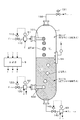
- FIG. 2 schematically shows the internal structure of the reactor 10 constituting the reaction unit 1 and the configuration of the control system provided in the reactor 10.
- the reactor 10 thermally decomposes the heavy oil by, for example, countercurrent contact between the heated and pressurized heavy oil and supercritical water. This serves to separate and extract the light oil and heavy oil obtained separately.
- a heavy oil supply line 110 to which heated and pressurized heavy oil is supplied is connected to the upper side of the reactor 10.
- a supercritical water supply line 120 to which heated and pressurized supercritical water is supplied is connected to the lower side of the reactor 10.
- 101 is a heavy oil supply nozzle
- 102 is a supercritical water supply nozzle.
- the light oil contained in the heavy oil in advance is extracted into supercritical water, and the heavy oil remaining without being extracted in the supercritical water is thermally decomposed.
- the light oil produced by the extraction into supercritical water forms a continuous phase consisting of supercritical water and light oil (hereinafter referred to as second phase), and heavy oil that has not been extracted into supercritical water.
- the oil component forms a continuous phase (hereinafter referred to as the first phase) and separates into two phases. Since the heavy oil has a higher specific gravity than the mixed fluid of supercritical water and light oil, the first phase is formed on the lower side of the reactor 10 and the second phase is formed on the upper side of the reactor 10. Will be.
- the heavy oil constituting the first phase contains heavy oil (dry condition standard containing no water). 3) to 100% by weight of supercritical water dissolves.
- the first phase is composed of a mixed fluid of heavy oil and supercritical water.
- supercritical water is supplied from the supercritical water supply nozzle 102 into the first phase on the lower side, and the heavy oil supply nozzle 101 is supplied into the second phase on the upper side. Will be supplied with heavy oil.
- extraction of light oil to the supercritical water side and dissolution to the heavy oil side of the supercritical water settles the interface with the supercritical water (dispersed phase) that rises the first phase and the second phase. It proceeds at the interface with the heavy oil (dispersed phase) and the contact interface between the first phase and the second phase.
- the present inventors have a very fast rising speed of supercritical water rising in the first phase, a very high sedimentation speed of heavy oil settling in the second phase, and each supercritical water and heavy oil is, for example, It is understood that it passes through the first and second phases in several seconds to several tens of seconds. For this reason, the pyrolysis of heavy oil actually proceeds with pyrolysis of the heavy oil in the first phase, and the resulting light oil is extracted to the second phase, and the second In this phase, further thermal decomposition of the light oil component and the light oil component supplied from the first phase side proceeds.
- a heavy oil content extraction line 140 is connected to the bottom of the reactor 10 to extract fluid (mixed fluid of heavy oil and supercritical water) constituting the first phase. Yes.
- the heavy oil content extraction line 140 is provided with a flow rate adjusting valve 142 that adjusts the amount of fluid extracted from the first phase.
- the fluid extracted from the heavy oil extraction line 140 is cooled by a cooler or the like, and thermal decomposition is stopped.
- a light oil content extraction line 130 for extracting fluid (mixed fluid of light oil content and supercritical water) constituting the second phase is connected to the top of the reactor 10.
- the light oil content extraction line 130 is provided with a pressure adjusting valve 131 for adjusting the pressure in the reactor 10 to, for example, 25 to 30 MPa.
- the fluid extracted from the light oil content extraction line 130 is also cooled by a cooler or the like, so that the thermal decomposition of the light oil content is stopped.
- the degree of thermal decomposition of the heavy oil component is determined by the mixed fluid of the heavy oil component in the first phase and the supercritical water dissolved in the heavy oil component (hereinafter, It can be controlled by the residence time of the first mixed fluid).
- the yield of light oil increases as the pyrolysis progresses, and supercritical water is dissolved in the heavy oil and the decomposition of the heavy oil is moderately advanced under the condition that the cage effect is exhibited.
- the viscosity of the heavy oil component decreases, and handling of the synthetic crude oil becomes easier when used as boiler fuel or after being mixed with the light oil component.
- pyrolysis proceeds to such an extent that the cage effect described above is offset, coke is generated in the heavy oil.
- the kinematic viscosity at, for example, 350 ° C. of the heavy oil as the residual oil is set to 3.0 ⁇ 10 ⁇ 5 m 2 / s or less (30 cSt or less), and coke is used.
- the thermal decomposition of the heavy oil component proceeds to such an extent that the production of coke is suppressed (for example, the amount of coke produced is in the range of 0 to 20% by weight of the heavy oil component).
- a mechanism for adjusting the residence time of the mixed fluid is set to 3.0 ⁇ 10 ⁇ 5 m 2 / s or less (30 cSt or less), and coke is used.
- the degree of progress of thermal decomposition of light oil is determined by the residence time of the mixed fluid of supercritical water in the second phase and the light oil extracted in the supercritical water (hereinafter referred to as the second mixed fluid). Can be adjusted.
- the light oil component has a kinematic viscosity that decreases as the thermal decomposition proceeds. For example, even in cold regions, it is possible to transport synthetic crude oil without providing special heating equipment. On the other hand, if the light oil component is excessively decomposed, the amount of gas generated from the light oil component increases, and the yield of synthetic crude oil decreases.
- the kinematic viscosity at 10 ° C. of the light crude oil alone or the synthetic crude oil mixed with the heavy oil is set to 5.0 ⁇ 10 ⁇ 3 m 2 / s or less (5000 cSt or less), and And a mechanism for adjusting the residence time of the second mixed fluid in the second phase so that the thermal decomposition of the light oil proceeds to such an extent that the generation of gas is suppressed.
- a heavy oil is mixed with a light oil to produce a synthetic crude, so the kinematic viscosity of the synthetic crude after mixing with the heavy oil is 5.0 ⁇ 10 ⁇ 3 m 2. / S or less (5000 cSt or less), the second residence time is adjusted so that the kinematic viscosity of the light oil alone mixed with the heavy oil having a relatively large kinematic viscosity becomes a lower value.
- the residence time of the first mixed fluid in the first phase is ⁇ pitch
- the residence time of the second mixed fluid in the second phase is ⁇ Lt
- the unit time of heavy oil from the heavy oil supply line 110 is F Oin is the supply amount per unit time
- F Win is the supply amount per unit time of supercritical water from the supercritical water supply line 120
- the first mixed fluid is extracted from the heavy oil content extraction line 140 per unit time.
- the ratio of the light oil extracted in the second phase varies depending on the properties of the heavy oil, the temperature and pressure conditions of the reactor 10, and the degree of thermal decomposition of the heavy oil. For example, a fraction lighter than VGO (Vacuumed Gas Oil: vacuum gas oil) having a boiling point of 540 ° C. or less is extracted as a light oil component to the supercritical water side, and the fraction corresponding to VR (Vacuumed Residue) having a boiling point higher than 540 ° C.
- VGO Vaumed Gas Oil: vacuum gas oil
- ⁇ pitch is controlled within, for example, a fluctuation range of about ⁇ 1 minute of the target value, and the degree of progress of thermal decomposition is controlled within a certain range, thereby obtaining the VGO yield (ie, VR). ) Is assumed to be almost constant.
- the flow rate withdrawn a flow rate withdrawn as heavy oil F Pitch, as light oil and F Lt, supercritical water is also fed to the reactor 10 flow rate F w1 withdrawn from the first phase by dissolving the heavy oil of, when a flow rate withdrawn from the second phase by extracting light oil and F w2, the first mixed fluid, the The extraction amount of the mixed fluid 2 is expressed by the following equations (3) and (4).
- F W1 + Pitch F W1 + F Pitch (3)
- FW2 + Lt FW2 + FLt (4)
- the first phase is increased or decreased by increasing or decreasing the extraction amount F W1 + Pitch of the first mixed fluid from the heavy oil content extraction line 140.
- the residence time ⁇ pitch of the first mixed fluid can be adjusted.
- the amount of coke produced is controlled within the range of 0 to 20% by weight of heavy oil, for example, and the kinematic viscosity of residual oil at 350 ° C is adjusted to 3.0 x 10 -5 m 2 / s or less (30 cSt or less). Make sure you can.
- the solubility of supercritical water in the heavy oil is constant under the conditions of constant temperature and pressure, if the outflow amount F Pitch of the heavy oil extracted from the first phase is determined, The amount F W1 of supercritical water dissolved in the refined oil is a constant value. If the supply amount F Win of the supercritical water is increased or decreased in this state, it is possible to increase or decrease the amount of supercritical water that does not dissolve in the heavy oil, that is, the amount F W2 of the supercritical water that forms the second phase. It becomes. Dissolution amount F W1 of supercritical water for outflow F Pitch of heavy oil, for example it is sufficient to understand due preliminary experiments.
- the residence time ⁇ Lt of the second mixed fluid in the second phase can be adjusted.
- the residence time ⁇ Lt within the range of “1 minute ⁇ ⁇ Lt ⁇ 25 minutes” from the results of the examples described later, For example, the production amount is suppressed within the range of 0 to 5% by mass of heavy oil, and the kinematic viscosity of light crude oil alone at 10 ° C. or synthetic crude oil after mixing with heavy oil is 5.0 ⁇ 10 ⁇ 3 m. It has been confirmed that it can be adjusted to 2 / s or less (5000 cSt or less).
- the heavy oil content extraction line 140 is provided with a flow rate controller 93 for adjusting the extraction amount FW1 + Pitch of the first mixed fluid, and the indicated value (b ) Is output to the control unit 9.
- the controller 9 calculates the residence time ⁇ pitch based on the formula (5), and increases or decreases the flow rate setting value (e) of the flow rate controller 93 so that the ⁇ pitch becomes a preset target value.
- the opening degree of 142 is adjusted.
- the flow rate adjustment valve 142 corresponds to the first flow rate adjustment unit.
- the supercritical water supply line 120 is provided with a flow rate controller 92 for adjusting the supply amount F Win (ie, F W2 ) of the supercritical water, and the indicated value (a) of the flow rate controller 92 is a control unit. 9 is output.
- the controller 9 calculates the residence time ⁇ Lt based on the equation (6), and increases or decreases the flow rate setting value (d) of the flow rate controller 93 so that the ⁇ Lt becomes a preset target value.
- the opening degree of 122 is adjusted.
- the reactor 10 is provided with an interface level meter 94 such as a differential pressure type, an ultrasonic type, an X-ray type, etc., which is an interface detection unit of the present embodiment, and the first phase in the reactor 10 and the first phase.
- an interface level meter 94 such as a differential pressure type, an ultrasonic type, an X-ray type, etc., which is an interface detection unit of the present embodiment, and the first phase in the reactor 10 and the first phase.
- a signal (c) indicating “high interface level” or “low interface level” is output to the control unit 9. .
- the control unit 9 increases or decreases the flow rate set value (f) of the flow rate controller 91 provided in the heavy oil supply line 110 so that the interface level returns to the height position within the set range, thereby supplying the heavy oil supply amount.
- the volume V 1 of the first phase (that is, the volume V 2 of the second phase) is kept constant.
- the pressure in the reactor 10 is determined by, for example, opening and closing the pressure regulating valve 131 by a pressure controller (not shown) provided in the light oil content line 310 of the high pressure separator 30 shown in FIG.
- the extraction amount of the second mixed fluid is adjusted.
- the pressure adjustment valve 131 corresponds to a second flow rate adjustment unit.
- an interface level meter 94 is provided to measure the interface between the first and second phases so that V 1 and V 2 are constant.
- the interface level meter 94 is not necessarily provided.
- the yields of lighter fractions and VR fractions than VGO according to the oil type, temperature, pressure conditions, etc. of heavy oil are obtained by experiments in advance, and F Oin , F Win , F Pitch , F
- the interface level in the reactor 10 is estimated from the values of Lt , F w1 , and F w2 , and V 1 and V 2 are kept constant based on the estimated interface level, and each based on the equations (5) and (6)
- the residence times ⁇ pitch and ⁇ Lt may be adjusted.
- the residence time ⁇ pitch of the first mixed fluid in the first phase is adjusted by the extraction amount F Pitch of the first mixed fluid
- the residence time of the second mixed fluid in the second phase is adjusted.
- ⁇ Lt is adjusted by the supply amount F Win of supercritical water
- these residence times are set to other operating variables shown in the equations (5) and (6), for example, the supply amount F of heavy oil It does not deny adjusting with Oin or the extraction amount FW2 + Ltout of the second mixed fluid.
- FIG. 3 shows a configuration example of the mixing unit 3.
- the mixing tank 21 into which the light oil obtained from the reaction unit 1 and a part or all of the heavy oil flow in, and the fluid in the mixing tank 21 are shown.
- an agitator 22 for agitating.
- the fluid mixed in the mixing tank 21 is sent to a pipeline or the like as synthetic crude oil.
- the mixing unit 3 may be configured by an in-line mixer 23.
- the in-line mixer 23 is provided, for example, on the downstream side of a joining portion of a pipe through which a light oil component flows and a pipe through which a part or all of the heavy oil component flows.
- the mixing ratio of the heavy oil to be mixed with the light oil in the mixing section 2 satisfies product standards set in advance for synthetic crude oil such as specific gravity (API (American Petroleum Institute) specific gravity and density) and viscosity. It is conceivable that the mixing ratio of the heavy oil is increased within the range. If it is a range which satisfies such a product specification, you may mix the whole quantity of the heavy oil part obtained from the reaction part 1 with a light oil part.
- product standards set in advance for synthetic crude oil such as specific gravity (API (American Petroleum Institute) specific gravity and density) and viscosity. It is conceivable that the mixing ratio of the heavy oil is increased within the range. If it is a range which satisfies such a product specification, you may mix the whole quantity of the heavy oil part obtained from the reaction part 1 with a light oil part.
- the light oil and heavy oil components are adjusted so that the compatibility of the synthetic crude oil after mixing is ensured, in other words, the mixing amount is within a range where the mixed synthetic crude oil is not re-separated into heavy and light oil components. It has become.
- the mixing ratio of the heavy oil in the synthetic oil is determined in consideration of the product specifications and compatibility of these synthetic crude oils, the yield of the heavy oil from the reactor 10, etc., but is limited to a specific ratio. It is not something.
- the reformed oil production apparatus reforms the heavy oil by bringing the heavy oil and supercritical water into contact with each other, and separates the heavy oil and the light oil into a reactor 10 (reaction unit), and the reactor 10.
- the high-pressure separator 30 that separates the mixed fluid of the light oil and supercritical water flowing out of the oil under a pressure condition similar to that in the reactor 10, for example, and the light oil and water flowing out of the high-pressure separator 30
- a low pressure separator 40 that separates the mixed fluid into oil and water under a pressure condition lower than that of the high pressure separator 30, and a mixed fluid of heavy oil and supercritical water that has flowed out of the reactor 10
- a flash drum 50 that performs separation and separation of a light fraction contained in a heavy oil component, and a separator 70 that separates a mixture of water flash-distilled in the flash drum 50 and a light fraction into oil and water.
- a recycled water tank 60 for recycling water after oil-water separation, and a.
- the reactor 10 is a pressure vessel formed in, for example, a tower shape having the configuration described with reference to FIG. 2, and heavy oil is supplied to the upper side wall portion of the reaction vessel from the heavy oil supply source 11, for example.
- a heavy oil supply line 110 for receiving is connected.
- the heavy oil supply source 11 includes, for example, a tank that stores heavy oil.
- the heavy oil supply line 110 increases the heavy oil received from the heavy oil supply source 11 to a critical pressure of water of 22.1 MPa or higher, for example, 25 MPa to 30 MPa, and sends the heavy oil to the reactor 10.
- a supply pump 111 and a heater 113 composed of, for example, a heating furnace for heating heavy oil supplied to the reactor 10 to, for example, 300 ° C. to 450 ° C. are interposed.
- the heavy oil is supplied at a temperature lower than the temperature in the reactor 10 (for example, 374 ° C. to 500 ° C.) in order to prevent polycondensation in the heavy oil supply line 110 and the heater 113.
- the heavy oil supply line 110, the heavy oil supply pump 111, the flow rate control valve 112, the heater 113, and the like correspond to the heavy oil supply unit of the present embodiment.
- a supercritical water supply line 120 for supplying water received from a water supply source 12 such as a water storage tank to the reactor 10 in a supercritical state is connected to, for example, the lower side wall portion of the reaction vessel.
- a supercritical water supply pump 121 that boosts the water received from the water supply source 12 to a critical pressure (22.1 MPa) or higher, for example, 25 MPa to 30 MPa, and sends the water toward the reactor 10;
- a flow control valve 122 for adjusting the supply amount of supercritical water, and a heating furnace for heating the supercritical water supplied to the reactor 10 to, for example, 450 ° C. to 600 ° C.
- the heater 123 which consists of these etc. is interposed.
- the heavy oil supplied from the heavy oil supply line 110 is supplied at a temperature lower than the temperature in the reactor 10 for the purpose of preventing polycondensation. Is supplied at a temperature higher than the temperature in the reactor 10 to supply heat necessary for the heavy oil pyrolysis reaction.
- the supercritical water supply line 120, the supercritical water supply pump 121, the flow control valve 122, the heater 123, and the like correspond to the supercritical water supply unit of the present embodiment.
- the light oil content extraction line 130 is connected.
- the light oil content extraction line 130 has a cooler 132 composed of a heat exchanger or the like for cooling the mixed fluid flowing in the light oil content extraction line 130 to a temperature lower than the critical pressure of water, for example, 200 ° C. to 374 ° C. It is installed.
- the mixed fluid cooled by the cooler 132 under a pressure substantially equal to the pressure in the reactor 10 is mixed with the light oil content (however, the light oil content also contains moisture).
- a high pressure separator 30 for separation into water.
- the light oil content line 310 includes a cooler 312 including a heat exchanger for cooling the light oil content to a temperature of about 40 ° C. to 100 ° C., and the pressure of the light oil content flowing in the line 310 from, for example, normal pressure.
- the pressure reducing valve 311 also has a function as the pressure adjusting valve 131 shown in FIG.
- a high-pressure separated water line 320 is provided on the bottom side of the high-pressure separator 30 for extracting water separated from the light oil under a pressure of about 25 MPa to 30 MPa and a temperature of about 200 ° C. to 374 ° C.
- the high-pressure separation water line 320 is connected to a later-described recycle water line 610 so that the separation water from the high-pressure separator 30 can be supplied to the reactor 10 again.
- Reference numeral 321 interposed in the high-pressure separation water line 320 is a high-pressure separation water recycle pump for feeding the separation water from the high-pressure separator 30.
- the low-pressure separator 40 has a pressure of about 0.2 MPa to 1.0 MPa with respect to the light oil content containing water flowing out from the high-pressure separator 30. Under the temperature condition of about 100 ° C. to 100 ° C., it again separates into light oil and water.
- Reference numeral 420 denotes a synthetic crude oil line for delivering light oil separated from water as synthetic crude oil to the synthetic crude oil tank 82.
- a low-pressure separation water recycling line 430 is connected to, for example, the bottom of the low-pressure separator 40.
- the low-pressure separation water recycling line 430 extracts water separated from light oil and recycles it as supercritical water. It plays the role of sending liquid to the tank 60.
- a drainage line 440 for extracting a part of the recycled water to the wastewater treatment facility 83 is branched from the low-pressure separated water recycle line 430, and it is improved by increasing or decreasing the amount of liquid fed to the wastewater treatment facility 83.
- the concentration of oil and salinity in the recycled water circulating in the quality oil production apparatus can be adjusted to a predetermined value or less.
- reference numeral 410 denotes an exhaust gas line for volatilizing the light oil but sending gas to the exhaust gas treatment facility 81.
- the high-pressure separator 30 and the low-pressure separator 40 described above correspond to the second separation unit of the present embodiment.
- a heavy oil extraction line 140 is connected to extract a fluid mixture of the heavy oil and supercritical water dissolved in the heavy oil from the second phase.
- the heavy oil content extraction line 140 includes a cooler 141 including a heat exchanger for cooling the mixed fluid flowing in the line 140 to about 200 ° C. to 350 ° C., and a mixture from the bottom of the reactor 10.
- a flow rate adjustment valve 142 is provided for adjusting the amount of fluid extracted and reducing the pressure of the mixed fluid flowing in the heavy oil content extraction line 140 to, for example, about 0.2 MPa to 1.0 MPa higher than normal pressure. It is installed.
- the flow control valve 142 is connected to the flash drum 50.
- the flash drum 50 performs flash distillation under a pressure condition of about 0.1 to 8 MPa and a temperature condition of about 250 to 430 ° C. It functions as a flash unit that separates water and light fractions dissolved in the oil.
- the heavy oil separated from the light oil in the reactor 10 contains a portion of the fraction corresponding to the light oil, and the production of synthetic crude oil is increased by collecting the light fraction. I am trying.
- a flash fluid line 510 connected to the flash drum 50 is a flash fluid line 510 for sending a mixed fluid of light fraction and water separated from heavy oil in the flash drum 50 to the separator 70 on the downstream side.
- a cooler 511 including a heat exchanger for cooling the fluid mixture of water and water to about 40 to 100 ° C. is interposed.
- Reference numeral 520 denotes a residual oil line for extracting heavy oil separated from water into a residual oil tank 84 as residual oil for boiler combustion, for example.
- the total or part of the heavy oil extracted from the flash drum 50 is mixed with the light oil extracted from the low-pressure separator 40 side and sent to the synthetic crude oil tank 82.
- a crude oil mixing line 530 is branched.
- the synthetic crude oil mixing line 530 is connected to the synthetic crude oil line 420 from the low pressure separator 40 as shown in FIG. 5, and the inline mixer 23 shown in FIG.
- the structure etc. which mix and manufacture synthetic crude oil can be illustrated.
- the joining part of the synthetic crude oil line 420 and the synthetic crude oil mixing line 530 corresponds to the mixing part 2 shown in FIG.
- a separator 70 Downstream of the flush fluid line 510, a separator 70 is provided as a first separation unit for separating a fluid separated from a heavy oil component by flash distillation into a light fraction and water.
- a light fraction line 710 for extracting a light fraction is provided on the upper side of the separator 30, and this light fraction line 710 is connected to a synthetic crude oil line 420 that delivers light oil from the low-pressure separator 40 described above. ing.
- recovered from heavy oil is mixed with light oil as a raw material of synthetic crude oil.
- the joining part of the light fraction line 710 and the synthetic crude oil line 420 corresponds to the light part mixing part of this example.
- a drum separation water line 720 is connected to the lower side of the separator 70 for extracting water separated from the light fraction in the separator 70 toward the separation water recycling line 430 and recycling the water.
- the light crude fraction is separated from the synthetic crude oil by the synthetic crude oil line 420.
- dehydration from the heavy oil becomes easier than when mixing without flash distillation.
- a recycled water tank 60 provided downstream of the low-pressure separated water recycling line 430 is separated into light separated from light oil by the low-pressure separator 40 and the separator 70. Accepts water separated from light fractions.
- the water collected in the recycled water tank 60 is supplied again to the supercritical water supply line 120.
- reference numeral 610 denotes a recycled water line that connects the recycled water tank 60 and the supercritical water supply line 120
- reference numeral 611 denotes water discharged from the recycled water tank 60 at a critical pressure (22.1 MPa) or more, for example, 22.1 MPa to This is a recycled water pump for raising the pressure to 40 MPa and sending it out toward the supercritical water supply line 120.
- the recycle water line 610 is joined with the high pressure separation water line 320 for recycling the water separated by the high pressure separator 30.
- the reformed oil production apparatus shown in FIG. 6 uses a heavy oil component in a state of a mixed fluid with supercritical water extracted from the first phase, to the supercritical water extracted from the second phase.
- the point which mixes with the light oil component of the state of a mixed fluid differs from the 1st structural example which mixes, after isolate
- the heavy oil content mixing line 150 is branched from the heavy oil content extraction line 140, and the heavy oil content mixing line 150 joins the light oil content extraction line 130 to constitute the mixing unit 2. .
- the heavy oil reforming apparatus has the following effects.
- heavy oil is brought into contact with supercritical water and pyrolyzed into heavy oil and light oil, and this oil is mixed with heavy oil to produce a modified oil.
- the modified oil can be obtained with a high yield.
- a configuration example of the mixing unit 2 is an example in which a heavy oil component is continuously mixed with a light crude oil component separated from water by connecting the synthetic crude oil mixing line 530 to the synthetic crude oil line 420 (FIGS. 5 and 6).
- the heavy oil content mixing line 150 is connected to the light oil content extraction line 130 and the heavy oil content is continuously mixed with the light oil content in the state of the mixed fluid with the supercritical fluid (FIG. 7). Absent.
- the synthetic crude oil mixing line 530 shown in FIG. 5 is not provided, but the entire amount of heavy oil is discharged from the residual oil line 520 to the residual oil tank 84, and the residual oil line 520 is supplied to the mixing tank 21 shown in FIG. It is good also as a structure which pays out heavy oil component toward and mixes with light oil component.
- the installation of the separator 70 shown in FIGS. 5 to 7 may be omitted.
- the flash drum 50 has conditions suitable for flushing only moisture from the heavy oil, such as a pressure condition in the range of about 0.4 to 1.0 MPa and a temperature condition in the range of about 200 to 350 ° C. Adjusted.
- recovered from the flash drum 50 is sent directly to a recycle water tank.
- the installation of the flash drum 50 may be omitted in the case where the heavy oil is mixed before the oil / water separation is performed by the light separator 40a.
- the boiler fuel and the fuel are still dispersed in the residual oil without depressurizing the first mixed fluid. By doing so, it becomes possible to further reduce the viscosity of the residual oil and make it easier to handle the residual oil.
- vaporization at the time of using as boiler fuel is accelerated
- the heavy oil to be reformed by the reformed oil manufacturing apparatus has been described for the case of processing ultra heavy crude oil such as oil sand bitumen or orinocotal.
- the heavy oil that can be processed in is not limited to crude oil.
- the case of performing reforming treatment of atmospheric distillation residue oil or vacuum distillation residue oil is also included in the technical scope of the present invention.
- the residence time ⁇ pitch of the first mixed fluid is the amount F Pitch of the residual oil extracted from the reactor 10
- the residence time ⁇ Lt of the second mixed fluid is the supply amount F Win of supercritical water. Controlled.
- As heavy oil Canadian oil sand bitumen having the properties shown in Table 1 was used. (Table 1)
- Example 1 The experiment was performed under the following conditions. Reaction temperature in reactor 10: 430 ° C Reaction pressure in reactor 10: 25 MPa Water / oil weight ratio: 1.0 Residence time ⁇ Pitch of the first fluid mixture: 95 minutes Residence time ⁇ Lt of the second fluid mixture: 2.3 minutes (Example 2) Reaction temperature in reactor 10: 450 ° C. The experiment was conducted under the same conditions as in Example 1 except that the residence time ⁇ Pitch of the first mixed fluid was 4.9 minutes and the residence time ⁇ Lt of the second fluid mixture was 11 minutes.
- Example 3 Water / oil weight ratio: 0.5 The experiment was performed under the same conditions as in Example 1 except that the residence time ⁇ Pitch of the first mixed fluid was 32 minutes and the residence time ⁇ Lt of the second fluid mixture was 25 minutes.
- Example 4 The experiment was performed under the same conditions as in Example 1 except that the residence time ⁇ Pitch of the first mixed fluid was 67 minutes and the residence time ⁇ Lt of the second fluid mixture was 1.8 minutes.
- Comparative Example 1 The experiment was performed under the same conditions as in Example 1 except that the residence time ⁇ Pitch of the first mixed fluid was 105 minutes and the residence time ⁇ Lt of the second fluid mixture was 1.1 minutes.
- Table 2 The experimental conditions of each example and comparative example are summarized in (Table 2). (Table 2)
- Example 6 the yield of each fraction obtained as a result of treating the same oil sand bitumen as used in (Example 1) by a bisbreaker test and a delayed coker test was compared with the results of (Examples 1 and 2). The results are shown in (Table 6).
- Examples 1 and 2 are obtained by synthesizing the yields of synthetic crude oil and residue wafers and converting them into a VGO fraction having a boiling point of 540 ° C. or lower and a VR fraction having a boiling point higher than 540 ° C. , (Table 3) may not match the yield. (Table 6)
- Example 2 ( ⁇ Pitch : 4.9 minutes) ⁇ Example 3 (same: 32 minutes) ⁇ Example 1 (same: 95 minutes) and first residence time ⁇ Pitch
- Example 3 (same: 32 minutes) ⁇ Example 1 (same: 95 minutes)
- first residence time ⁇ Pitch As the oil length is increased, the yield of residual oil decreases while the yield of synthetic crude oil increases. Further, in Comparative Example 1 where the ⁇ pitch was 105 minutes, generation of coke (coking) was observed.
- Example 4 ( ⁇ Pitch : 67 minutes) in which the first residence time ⁇ Pitch is longer than that in Example 3, the residual oil yield is higher than that in Example 3, while the synthetic crude oil yield is The reason for this is not clear, but I think it is due to fluctuation error.
- Example 4 (same as 1.8 minutes) ⁇ Example 2 (same as 11: except for Example 1 ( ⁇ Lt : 2.3 minutes) with the highest gas yield).
- Min ⁇ Example 3 (25 minutes in the same order)
- the gas yield tends to increase as the second residence time ⁇ Lt is increased.
- Example 4 ( ⁇ Lt : 1.8 minutes) ⁇ Example 1 (same: 2.3 minutes) ⁇ Example 2 (same: 11 minutes) ⁇ Example 3 (same: 25 minutes) and second
- ⁇ Lt the residence time
- the kinematic viscosity of the residual oil tends to increase. This is considered to be the result of the polymerization of the heavy oil proceeding against the cage effect of supercritical water dissolved in the heavy oil as the first residence time is increased. This can also be confirmed from the fact that the density of the residual oil increases as the first residence time increases.
- the first residence time ⁇ Pitch should be in the range of about 3 minutes to 95 minutes.
- the kinematic viscosity at 310 ° C. becomes 1.8 ⁇ 10 ⁇ 5 m 2 / s (18 cSt) or less while suppressing the generation of coke, and it can be seen that a residual oil that is easy to handle can be obtained.
- the second residence time ⁇ Lt is about 1 to 25 minutes, and the gas generation is suppressed to about 4% by mass or less, and the kinematic viscosity at 10 ° C. is 2.8 ⁇ 10 ⁇ 5 m. It can be said that synthetic crude oil of 2 / s (28 cSt) or less can be obtained.
- Example 3-2 The same experiment as in Example 3-2 was performed except that the residence time ⁇ Pitch of the first fluid mixture was 25.7 minutes and the residence time ⁇ Lt of the second fluid mixture was 7.7 minutes.
- Example 3-3 The same experiment as in Example 3-2 was performed, except that the residence time ⁇ Pitch of the first fluid mixture was 37.7 minutes and the residence time ⁇ Lt of the second fluid mixture was 4.0 minutes.
- Table 7 summarizes the experimental conditions of the examples. (Table 7)
- Example 3-1 the mixing ratio of the heavy oil in the synthetic crude oil was 2.0% by weight, and the synthetic crude oil yield was 39.3% by weight. This indicates that the yield of synthetic crude oil was increased by 0.8% by weight compared to the light oil yield (38.5% by weight) shown in (Table 7).
- Example 3-2 the mixing ratio of the heavy oil in the synthetic crude oil was 2.6% by weight, and the yield of the synthetic crude oil was 44.5% by weight. This indicates that the yield of the synthetic crude oil was increased by 1.2% by weight compared to the light oil yield (43.3% by weight) shown in (Table 7).
- Example 3-3 the mixing ratio of the heavy oil in the synthetic crude oil was 8.1% by weight, and the yield of the synthetic crude oil was 65.1% by weight. This indicates that the yield of the synthetic crude oil was increased by 5.3% by weight compared to the light oil yield (59.8% by weight) shown in (Table 7). None of the synthetic crude oils obtained in Examples 3-1 to 3-3 had compatibility problems, and heavy oil was brought into contact with supercritical water to thermally decompose it into heavy oil and light oil. It was confirmed that synthetic crude oil (modified oil) can be produced by mixing heavy oil with light oil.
Abstract
Description
以上のように、既存の技術では副生成物の処理、水素の製造、触媒の供給、廃触媒の処理が問題となる。
(1)反応部に重質油を供給する工程と、
前記反応部に超臨界水を供給する工程と、
前記反応部内を水の臨界点以上の温度、圧力に維持し、重質油と超臨界水とを接触させて、当該重質油を熱分解する工程と、
前記重質油が熱分解して得られた重質油分と前記重質油分中に溶解した超臨界水とからなる第1の相を前記反応部の下部に、前記超臨界水と、前記超臨界水中に抽出された軽質油分とからなる第2の相を前記反応部の上部に、それぞれ形成する工程と、
前記重質油分におけるコークスの形成を抑えるように、前記第1の相における第1の混合流体を、前記反応部の下部から抜き出す工程と、
前記軽質油分からのガス生成を抑えるように、前記第2の相における第2の混合流体を、前記反応部の上部から抜き出す工程と、
前記第2の混合流体の軽質油分に、前記第1の混合流体の重質油分を混合して、改質油を得る工程と、を含むことを特徴とする改質油の製造方法。
(2)前記第1の混合流体をフラッシュ蒸留して、前記第1の相の重質油分に含まれる軽質留分と水との混合蒸気と、残りの重質油分とに分離する工程と、
前記混合蒸気を冷却して、軽質留分と水とに分離する工程と、
前記第2の混合流体の軽質油分に、前記軽質留分を混合する工程と、を含み、
前記改質油を得る工程では、前記フラッシュ蒸留後の重質油分が軽質油分に混合されることを特徴とする(1)に記載の改質油の製造方法。
(3)前記第2の混合流体を、軽質油分と水とに分離する工程を含み、
前記改質油を得る工程では、前記水と分離された後の軽質油分に重質油分が混合されることを特徴とする(1)又は(2)に記載の改質油の製造方法。
(4)前記軽質油分への重質油分の混合量は、前記改質油に予め設定された比重または粘度の規格を満たす範囲内の量であることを特徴とする(1)~(3)の何れかに記載の改質油の製造方法。
(5)前記第1の相における前記第1の混合流体の滞留時間は、
i)3分以上、95分以下の範囲内、
ii)コークスの生成量が前記重質油分の0重量%以上、20重量%以下となる範囲内で前記重質油の熱分解を進行させる滞留時間、
iii)350℃における前記重質油分の動粘度が3.0×10⁻⁵m2/s以下となるまで前記重質油の熱分解を進行させる滞留時間、の何れかとなるように、前記第1の混合流体の抜き出し量を制御する工程を含むことを特徴とする(1)~(4)の何れかに記載の改質油の製造方法。
(6)前記第2の相における前記第2の混合流体の滞留時間は、
i)前記軽質油分の過分解を抑えるため、前記第2の滞留時間を1分以上、25分以下の範囲内、
ii)過分解によるガスの生成量が前記重質油の0重量%以上、5重量%以下となる範囲内で前記重質油の熱分解を進行させる滞留時間、
iii)10℃における前記軽質油分の動粘度が5.0×10⁻³m2/s以下となるまで前記重質油の熱分解を進行させる滞留時間、の何れかとなるように、前記反応部への超臨界水の供給量を制御する工程を含むことを特徴とする(1)~(5)の何れかに記載の改質油の製造方法。
(7)前記重質油は、オイルサンドビチュメン、オリノコタール、常圧蒸留残渣油、減圧蒸留残渣油からなる重質油群から選ばれることを特徴とする(1)~(6)の何れかに記載の改質油の製造方法。
前記重質油分におけるコークスの形成を抑えるように、前記第1の相における重質油分及び当該重質油分中に溶解した超臨界水の第1の混合流体を、前記反応部の下部から抜き出す第1の流量調節部と、
前記軽質油分からのガス生成を抑えるように、前記第2の相における第2の混合流体を、前記反応部の上部から抜き出す第2の流量調節部と、
前記反応部の上部から抜き出された前記第2の混合流体の軽質油分に、前記第1の混合流体の重質油分を混合して、改質油を得る混合部と、
を備えることを特徴とする改質油製造装置。
(9)前記第1の混合流体をフラッシュ蒸留して、当該前記第1の相の重質油分に含まれる軽質留分と水との混合蒸気と、残りの重質油分とに分離するためのフラッシュ部と、
前記混合蒸気を冷却して、軽質留分と水とに分離するための第1の分離部と、
前記第2の混合流体の軽質油分に、前記軽質留分を混合するための軽質留分混合部と、を備え、
前記混合部では、前記フラッシュ蒸留後の重質油分が軽質油分に混合されることを特徴とする(8)に記載の改質油製造装置。
(10)前記第2の混合流体を、軽質油分と水とに分離するための第2の分離部を備え、
前記混合部では、前記水と分離された後の軽質油分に重質油分が混合されることを特徴とする(8)又(9)に記載の改質油製造装置。
(11)前記軽質油分への重質油分の混合量は、前記改質油に予め設定された比重または粘度の規格を満たす範囲内の量であることを特徴とする(8)~(10)の何れかに記載の改質油製造装置。
(12)前記第1の相における前記第1の混合流体の滞留時間が、
i)3分以上、95分以下の範囲内、
ii)コークスの生成量が前記重質油分の0重量%以上、20重量%以下となる範囲内で前記重質油の熱分解を進行させる滞留時間、
iii)350℃における前記重質油分の動粘度が3.0×10⁻⁵m2/s以下となるまで前記重質油の熱分解を進行させる滞留時間、の何れかとなるように、前記第1の混合流体の抜き出し量を制御する制御部を備えることを特徴とする(8)~(11)の何れかに記載の改質油製造装置。
(13)前記第2の相における前記第2の混合流体の滞留時間が、
i)前記軽質油分の過分解を抑えるため、前記第2の滞留時間を1分以上、25分以下の範囲内、
ii)過分解によるガスの生成量が前記重質油の0重量%以上、5重量%以下となる範囲内で前記重質油の熱分解を進行させる滞留時間、
iii)10℃における前記軽質油分の動粘度が5.0×10⁻³m2/s以下となるまで前記重質油の熱分解を進行させる滞留時間、の何れかとなるように、前記反応部への超臨界水の供給量を制御する制御部を備えることを特徴とする(8)~(12)の何れかに記載の改質油製造装置。
(14)前記重質油は、オイルサンドビチュメン、オリノコタール、常圧蒸留残渣油、減圧蒸留残渣油からなる重質油群から選ばれることを特徴とする(8)~(13)の何れかに記載の改質油製造装置。
本発明の実施の形態に係わる改質油製造装置の基本構成について説明する。改質油製造装置は、例えばオイルサンドビチュメンやオリノコタールなどの高密度、高粘度の原油が生産される井戸元などに設置され、当該重質油から低密度、低粘度の合成原油を製造する役割を果たす。
図2は前記反応部1を構成する反応器10の内部構造及び当該反応器10に設けられた制御系統の構成を模式的に示している。反応器10は、昇温、昇圧された重質油と超臨界水とを例えば向流接触させることにより当該重質油を熱分解し。これにより得られた軽質油分と重質油分とを別々に分離して抜き出す役割を果たす。反応器10の上部側には、加熱、昇圧された重質油が供給される重質油供給ライン110が接続されている。一方、反応器10の下部側には、加熱、昇圧された超臨界水が供給される超臨界水供給ライン120が接続されている。そして、両流体が反応器10内で接触すると超臨界水により持ち込まれた熱により重質油の熱分解が進行して重質油全体が軽質化することになる。ここで図2に示した101は重質油の供給ノズル、102は超臨界水の供給ノズルである。
以上に説明した熱分解機構によれば、重質油分の熱分解の進行度合いは、第1の相内における重質油分とこの重質油分中に溶解した超臨界水との混合流体(以下、第1の混合流体という)の滞留時間にて制御することができる。重質油は熱分解を進行させるほど軽質油分の収率が増え、また重質油分中に超臨界水を溶解させてケージ効果が発揮される条件下で重質油分の分解を適度に進行させることにより、重質油分の粘度が低下してボイラー燃料などとして使用する際や軽質油分と混合された後の合成原油のハンドリングが容易になる。一方で、既述のケージ効果が相殺される程度まで熱分解が進行してしまうと重質油分中にコークスが生成される。
FOin+FWin=FW1+Pitch+FW2+Lt…(2)
FW1+Pitch=FW1+FPitch…(3)
FW2+Lt=FW2+FLt…(4)
θpitch=V1/FW1+Pitch
=V1/(FW1+FPitch)…(5)
θLt=V2/FW2+Lt
=V2/(FW2+FLt)…(6)
ここで反応器10内の圧力は例えば後述の図5に示す高圧セパレーター30の軽質油分ライン310に設けられた不図示の圧力コントローラーにより、圧力調整弁131を開閉することにより行われ反応器10からの第2の混合流体の抜き出し量が調節される。この観点で圧力調整弁131は、第2の流量調節部に相当する。
図3は、混合部3の構成例を示しており、反応部1より得られた軽質油分と、重質油分の一部、または全量とが流入する混合タンク21と、混合タンク21内の流体を攪拌する攪拌機22と、を備えている。混合タンク21内で混合された流体は、合成原油としてパイプライン等へ送られる。また、図4に示すように混合部3は、インラインミキサー23にて構成してもよい。インラインミキサー23は、例えば軽質油分が通流する配管と、重質油分の一部、または全量が通流する配管との合流部の下流側に設けられる。
以上に説明した改質油製造装置の具体的な構成例について図5を参照しながら説明する。改質油製造装置は、重質油と超臨界水とを接触させて当該重質油を改質し、重質油分と軽質油分とに分離する反応器10(反応部)と、反応器10から流出した軽質油分と超臨界水との混合流体を例えば反応器10内の圧力と同程度の圧力条件下で油水分離する高圧セパレーター30と、この高圧セパレーター30から流出した軽質油と水との混合流体を高圧セパレーター30よりも低い圧力条件下で油水分離する低圧セパレーター40と、反応器10から流出した重質油分と超臨界水との混合流体を反応器10よりも低い圧力条件下で油水分離、並びに、重質油分中に含まれている軽質留分の分離を行うフラッシュドラム50と、フラッシュドラム50にてフラッシュ蒸留された水と軽質留分の混合流体を油水分離するセパレーター70と、油水分離後の水をリサイクルするためのリサイクル水タンク60と、を備えている。
図6に示した改質油製造装置は、第1の相から抜き出された超臨界水との混合流体の状態の重質油分を、第2の相から抜き出された超臨界水との混合流体の状態の軽質油分に混合する点が、重質油分や軽質油分から水を分離してから混合を行う第1の構成例と異なっている。本例では、重質油分抜出ライン140より重質油分混合ライン150が分岐しており、この重質油分混合ライン150が軽質油分抜出ライン130に合流して混合部2を構成している。
上述の改質油製造装置をモデルとした試験装置を製作し、重質油の改質実験を行った。
本装置では第1の混合流体の滞留時間θpitchは反応器10からの残渣油の抜き出し量FPitch、第2の混合流体の滞留時間θLtは超臨界水の供給量FWinにて制御した。重質油としては(表1)に示す性状のカナダ産のオイルサンドビチュメンを使用した。
(表1)

以下の条件で実験を行った。
反応器10内の反応温度:430℃
反応器10内の反応圧力:25MPa
水/油重量比:1.0
第1の混合流体の滞留時間θPitch:95分
第2の混合流体の滞留時間θLt:2.3分
(実施例2)
反応器10内の反応温度:450℃
第1の混合流体の滞留時間θPitch:4.9分
第2の混合流体の滞留時間θLt:11分
とした他は(実施例1)同様の条件で実験を行った。
(実施例3)
水/油重量比:0.5
第1の混合流体の滞留時間θPitch:32分
第2の混合流体の滞留時間θLt:25分
とした他は(実施例1)同様の条件で実験を行った。
(実施例4)
第1の混合流体の滞留時間θPitch:67分
第2の混合流体の滞留時間θLt:1.8分
とした他は(実施例1)同様の条件で実験を行った。
(比較例1)
第1の混合流体の滞留時間θPitch:105分
第2の混合流体の滞留時間θLt:1.1分
とした他は(実施例1)同様の条件で実験を行った。
各実施例、比較例の実験条件を(表2)にまとめた。
(表2)

(表3)に各実施例、比較例におけるガス、合成原油(軽質油分)、残渣油(重質油分)の収率を示す。(表4)に合成原油性状、(表5)に残渣油性状を示す。本実験では軽質油分への重質油分の混合は実施していない。
(表3)


(表6)

[実験1]と同様の実験装置の反応器1に内部観察用の覗き窓を設け、容器内の流体が第1の相と第2の相とに分離し、界面が形成されることを確認した。目視の結果、反応器1の下部側には、重質油分とこの重質油分中に溶解した超臨界水とからなる第1の相と、超臨界水とこの超臨界水中に抽出された軽質油分とからなる第2の相とが確認された。
重質油の改質実験にて得られた重質油分、軽質油分を混合して合成原油を製造する実験を行った。
実験1と同様の実験装置にて、第1の混合流体の滞留時間θPitch、第2の混合流体の滞留時間θLtを変化させて(表1)に示した性状のオイルサンドビチュメンを処理した。得られた軽質油分及び重質油分の性状に基づいて、軽質油分への重質油分の混合可能量を検討した。反応器10内の反応温度は430℃、反応温度は25MPa、水/油比は1で一定とした。
(実施例3-1)
第1の混合流体の滞留時間θPitchを9.7分、第2の混合流体の滞留時間θLtを6.7分とし、合成原油のAPI比重が21.0°となるように、軽質油分への重質油分の混合可能量を求めた。
(実施例3-2)
第1の混合流体の滞留時間θPitchを25.7分、第2の混合流体の滞留時間θLtを7.7分とした点以外は(実施例3-2)と同様の実験を行った。
(実施例3-3)
第1の混合流体の滞留時間θPitchを37.7分、第2の混合流体の滞留時間θLtを4.0分とした点以外は(実施例3-2)と同様の実験を行った。
(表7)に実施例の実験条件をまとめて示す。
(表7)
実施例3-1~3-3の実験にて得られた軽質油分、重質油分、ガスの収率、並びに軽質油分、重質油分の密度とAPI比重を(表8)に示す。また、合成原油の製品規格をAPI比重21.0に設定したときの軽質油分及び重質油分の混合割合、合成原油の収率を(表9)に示す。


実施例3-1では、合成原油中の重質油分の混合割合を2.0重量%として、合成原油収率を39.3重量%とすることができた。これは、(表7)に示した軽質油分の収率(38.5重量%)に比べて合成原油の収率を0.8重量%増産できたことを示している。また、実施例3-2では、合成原油中の重質油分の混合割合を2.6重量%として、合成原油の収率を44.5重量%とすることができた。これは、(表7)に示した軽質油分の収率(43.3重量%)に比べて合成原油の収率を1.2重量%増産できたことを示している。さらに、実施例3-3では、合成原油中の重質油分の混合割合を8.1重量%として、合成原油の収率を65.1重量%とすることができた。これは、(表7)に示した軽質油分の収率(59.8重量%)に比べて合成原油の収率を5.3重量%増産できたことを示している。実施例3-1~3-3で得られた合成原油のいずれにも相溶性の問題はなく、重質油を超臨界水と接触させて重質油分と軽質油分とに熱分解し、この軽質油分に重質油分を混合することにより合成原油(改質油)を製造できることが確認できた。
110 重質油供給ライン
112 流量調節弁
120 超臨界水供給ライン
122 流量調節弁
130 軽質油分抜出ライン
131 圧力調整弁
140 重質油分抜出ライン
142 流量調節弁
2 混合部
30 高圧セパレーター
40 低圧セパレーター
50 フラッシュドラム
60 リサイクル水タンク
70 セパレーター
9 制御部
Claims (12)
- 反応部に重質油を供給する工程と、
前記反応部に超臨界水を供給する工程と、
前記反応部内を水の臨界点以上の温度、圧力に維持し、重質油と超臨界水とを接触させて、当該重質油を熱分解する工程と、
前記重質油が熱分解して得られた重質油分と前記重質油分中に溶解した超臨界水とからなる第1の相を前記反応部の下部に、前記超臨界水と、前記超臨界水中に抽出された軽質油分とからなる第2の相を前記反応部の上部に、それぞれ形成する工程と、
前記重質油分におけるコークスの形成を抑えるように、前記第1の相における第1の混合流体を、前記反応部の下部から抜き出す工程と、
前記軽質油分からのガス生成を抑えるように、前記第2の相における第2の混合流体を、前記反応部の上部から抜き出す工程と、
前記第2の混合流体の軽質油分に、前記第1の混合流体の重質油分を混合して、改質油を得る工程と、を含むことを特徴とする改質油の製造方法。 - 前記第1の混合流体をフラッシュ蒸留して、前記第1の相の重質油分に含まれる軽質留分と水との混合蒸気と、残りの重質油分とに分離する工程と、
前記混合蒸気を冷却して、軽質留分と水とに分離する工程と、
前記第2の混合流体の軽質油分に、前記軽質留分を混合する工程と、を含み、
前記改質油を得る工程では、前記フラッシュ蒸留後の重質油分が軽質油分に混合されることを特徴とする請求項1に記載の改質油の製造方法。 - 前記第2の混合流体を、軽質油分と水とに分離する工程を含み、
前記改質油を得る工程では、前記水と分離された後の軽質油分に重質油分が混合されることを特徴とする請求項1又は2に記載の改質油の製造方法。 - 前記軽質油分への重質油分の混合量は、前記改質油に予め設定された比重または粘度の規格を満たす範囲内の量であることを特徴とする請求項1~3の何れか1項に記載の改質油の製造方法。
- 前記第1の相における前記第1の混合流体の滞留時間は、
i)3分以上、95分以下の範囲内、
ii)コークスの生成量が前記重質油分の0重量%以上、20重量%以下となる範囲内で前記重質油の熱分解を進行させる滞留時間、
iii)350℃における前記重質油分の動粘度が3.0×10⁻⁵m2/s以下となるまで前記重質油の熱分解を進行させる滞留時間、の何れかとなるように、前記第1の混合流体の抜き出し量を制御する工程を含むことを特徴とする請求項1~4の何れか1項に記載の改質油の製造方法。 - 前記第2の相における前記第2の混合流体の滞留時間は、
i)前記軽質油分の過分解を抑えるため、前記第2の滞留時間を1分以上、25分以下の範囲内、
ii)過分解によるガスの生成量が前記重質油の0重量%以上、5重量%以下となる範囲内で前記重質油の熱分解を進行させる滞留時間、
iii)10℃における前記軽質油分の動粘度が5.0×10⁻³m2/s以下となるまで前記重質油の熱分解を進行させる滞留時間、の何れかとなるように、前記反応部への超臨界水の供給量を制御する工程を含むことを特徴とする請求項1~5の何れか1項に記載の改質油の製造方法。 - 水の臨界点以上の温度、圧力に維持され、重質油と超臨界水とを接触させて、当該重質油の熱分解を進行させつつ、この重質油が熱分解して得られた重質油分とこの重質油分中に溶解した超臨界水とからなる第1の相を下部に、前記超臨界水と、前記超臨界水中に抽出された軽質油分とからなる第2の相を上部に形成する反応部と、
前記重質油分におけるコークスの形成を抑えるように、前記第1の相における重質油分及び当該重質油分中に溶解した超臨界水の第1の混合流体を、前記反応部の下部から抜き出す第1の流量調節部と、
前記軽質油分からのガス生成を抑えるように、前記第2の相における第2の混合流体を、前記反応部の上部から抜き出す第2の流量調節部と、
前記反応部の上部から抜き出された前記第2の混合流体の軽質油分に、前記第1の混合流体の重質油分を混合して、改質油を得る混合部と、
を備えることを特徴とする改質油製造装置。 - 前記第1の混合流体をフラッシュ蒸留して、前記第1の相の重質油分に含まれる軽質留分と水との混合蒸気と、残りの重質油分とに分離するためのフラッシュ部と、
前記混合蒸気を冷却して、軽質留分と水とに分離するための第1の分離部と、
前記第2の混合流体の軽質油分に、前記軽質留分を混合するための軽質留分混合部と、を備え、
前記混合部では、前記フラッシュ蒸留後の重質油分が軽質油分に混合されることを特徴とする請求項7に記載の改質油製造装置。 - 前記第2の混合流体を、軽質油分と水とに分離するための第2の分離部を備え、
前記混合部では、前記水と分離された後の軽質油分に重質油分が混合されることを特徴とする請求項7又8に記載の改質油製造装置。 - 前記軽質油分への重質油分の混合量は、前記改質油に予め設定された比重または粘度の規格を満たす範囲内の量であることを特徴とする請求項7~9の何れか1項に記載の改質油製造装置。
- 前記第1の相における前記第1の混合流体の滞留時間が、
i)3分以上、95分以下の範囲内、
ii)コークスの生成量が前記重質油分の0重量%以上、20重量%以下となる範囲内で前記重質油の熱分解を進行させる滞留時間、
iii)350℃における前記重質油分の動粘度が3.0×10⁻⁵m2/s以下となるまで前記重質油の熱分解を進行させる滞留時間、の何れかとなるように、前記第1の混合流体の抜き出し量を制御する制御部を備えることを特徴とする請求項7~10の何れか1項に記載の改質油製造装置。 - 前記第2の相における前記第2の混合流体の滞留時間が、
i)前記軽質油分の過分解を抑えるため、前記第2の滞留時間を1分以上、25分以下の範囲内、
ii)過分解によるガスの生成量が前記重質油の0重量%以上、5重量%以下となる範囲内で前記重質油の熱分解を進行させる滞留時間、
iii)10℃における前記軽質油分の動粘度が5.0×10⁻³m2/s以下となるまで前記重質油の熱分解を進行させる滞留時間、の何れかとなるように、前記反応部への超臨界水の供給量を制御する制御部を備えることを特徴とする請求項7~11の何れか1項に記載の改質油製造装置。
Priority Applications (2)
| Application Number | Priority Date | Filing Date | Title |
|---|---|---|---|
| PCT/JP2011/002297 WO2012143972A1 (ja) | 2011-04-19 | 2011-04-19 | 改質油の製造方法、及び改質油製造装置 |
| CA2772095A CA2772095C (en) | 2011-04-19 | 2011-04-19 | Method for producing upgraded oil, and apparatus for producing upgraded oil |
Applications Claiming Priority (1)
| Application Number | Priority Date | Filing Date | Title |
|---|---|---|---|
| PCT/JP2011/002297 WO2012143972A1 (ja) | 2011-04-19 | 2011-04-19 | 改質油の製造方法、及び改質油製造装置 |
Publications (1)
| Publication Number | Publication Date |
|---|---|
| WO2012143972A1 true WO2012143972A1 (ja) | 2012-10-26 |
Family
ID=47022402
Family Applications (1)
| Application Number | Title | Priority Date | Filing Date |
|---|---|---|---|
| PCT/JP2011/002297 WO2012143972A1 (ja) | 2011-04-19 | 2011-04-19 | 改質油の製造方法、及び改質油製造装置 |
Country Status (2)
| Country | Link |
|---|---|
| CA (1) | CA2772095C (ja) |
| WO (1) | WO2012143972A1 (ja) |
Cited By (4)
| Publication number | Priority date | Publication date | Assignee | Title |
|---|---|---|---|---|
| JP2017504685A (ja) * | 2013-12-18 | 2017-02-09 | サウジ アラビアン オイル カンパニー | 超臨界水による品質向上させた石油の製造 |
| CN107474871A (zh) * | 2017-09-18 | 2017-12-15 | 张冰童 | 一种催化重整生成油脱烯烃的方法和催化剂 |
| JP2019049006A (ja) * | 2013-07-02 | 2019-03-28 | サウディ ベーシック インダストリーズ コーポレイション | 原油を石油化学製品に転化する、炭素利用率の改善された方法および装置 |
| JP2020512442A (ja) * | 2017-03-08 | 2020-04-23 | サウジ アラビアン オイル カンパニー | 重油の質を向上させるための統合型水熱プロセス |
Families Citing this family (1)
| Publication number | Priority date | Publication date | Assignee | Title |
|---|---|---|---|---|
| DK179687B1 (en) * | 2017-03-30 | 2019-03-25 | Steeper Energy Aps | High pressure treatment system separation system |
Citations (5)
| Publication number | Priority date | Publication date | Assignee | Title |
|---|---|---|---|---|
| JP2003049180A (ja) * | 2001-08-07 | 2003-02-21 | Hitachi Ltd | 重質油の軽質化方法 |
| JP2008297443A (ja) * | 2007-05-31 | 2008-12-11 | Japan Energy Corp | 炭化水素油の分解方法 |
| JP2008297466A (ja) * | 2007-05-31 | 2008-12-11 | Japan Energy Corp | 炭化水素油の分解方法 |
| WO2009082585A2 (en) * | 2007-11-28 | 2009-07-02 | Saudi Arabian Oil Company | Process to upgrade whole crude oil by hot pressurized water and recovery fluid |
| JP2011088964A (ja) * | 2009-10-20 | 2011-05-06 | Jgc Corp | 重質油の改質装置及び重質油の改質方法 |
-
2011
- 2011-04-19 CA CA2772095A patent/CA2772095C/en not_active Expired - Fee Related
- 2011-04-19 WO PCT/JP2011/002297 patent/WO2012143972A1/ja active Application Filing
Patent Citations (5)
| Publication number | Priority date | Publication date | Assignee | Title |
|---|---|---|---|---|
| JP2003049180A (ja) * | 2001-08-07 | 2003-02-21 | Hitachi Ltd | 重質油の軽質化方法 |
| JP2008297443A (ja) * | 2007-05-31 | 2008-12-11 | Japan Energy Corp | 炭化水素油の分解方法 |
| JP2008297466A (ja) * | 2007-05-31 | 2008-12-11 | Japan Energy Corp | 炭化水素油の分解方法 |
| WO2009082585A2 (en) * | 2007-11-28 | 2009-07-02 | Saudi Arabian Oil Company | Process to upgrade whole crude oil by hot pressurized water and recovery fluid |
| JP2011088964A (ja) * | 2009-10-20 | 2011-05-06 | Jgc Corp | 重質油の改質装置及び重質油の改質方法 |
Non-Patent Citations (3)
| Title |
|---|
| MASARU WATANABE ET AL., J. OF SUPERCRITICAL FLUIDS, 2010, pages 48 - 52 * |
| SHINSUKE KOKUBO ET AL., J. JPN. PETROL. INST., vol. 51, no. 5, 2008, pages 309 - 314 * |
| YUMA SAKAMOTO ET AL., SEKIYU - SEKIYU KAGAKU TORONKAI KOEN YOSHI, 2009, pages 181 * |
Cited By (7)
| Publication number | Priority date | Publication date | Assignee | Title |
|---|---|---|---|---|
| JP2019049006A (ja) * | 2013-07-02 | 2019-03-28 | サウディ ベーシック インダストリーズ コーポレイション | 原油を石油化学製品に転化する、炭素利用率の改善された方法および装置 |
| US10676681B2 (en) | 2013-07-02 | 2020-06-09 | Saudi Basic Industries Corporation | Process and installation for the conversion of crude oil to petrochemicals having an improved carbon-efficiency |
| JP2017504685A (ja) * | 2013-12-18 | 2017-02-09 | サウジ アラビアン オイル カンパニー | 超臨界水による品質向上させた石油の製造 |
| JP2020512442A (ja) * | 2017-03-08 | 2020-04-23 | サウジ アラビアン オイル カンパニー | 重油の質を向上させるための統合型水熱プロセス |
| US11149216B2 (en) | 2017-03-08 | 2021-10-19 | Saudi Arabian Oil Company | Integrated hydrothermal process to upgrade heavy oil |
| JP7029464B2 (ja) | 2017-03-08 | 2022-03-03 | サウジ アラビアン オイル カンパニー | 重油の質を向上させるための統合型水熱プロセス |
| CN107474871A (zh) * | 2017-09-18 | 2017-12-15 | 张冰童 | 一种催化重整生成油脱烯烃的方法和催化剂 |
Also Published As
| Publication number | Publication date |
|---|---|
| CA2772095A1 (en) | 2012-10-19 |
| CA2772095C (en) | 2015-05-05 |
Similar Documents
| Publication | Publication Date | Title |
|---|---|---|
| WO2011048642A1 (ja) | 重質油の改質装置及び重質油の改質方法 | |
| JP5514118B2 (ja) | 高温加圧水及び回収流体により全原油を品質改良する方法 | |
| US20090166261A1 (en) | Upgrading heavy hydrocarbon oils | |
| US10344228B2 (en) | Supercritical water upgrading process to produce high grade coke | |
| US20090159498A1 (en) | Intergrated process for in-field upgrading of hydrocarbons | |
| EP3565871B1 (en) | Processes for deasphalting oil | |
| US20080230440A1 (en) | Methods and Systems for Producing Reduced Resid and Bottomless Products from Heavy Hydrocarbon Feedstocks | |
| WO2012143972A1 (ja) | 改質油の製造方法、及び改質油製造装置 | |
| MX2012007075A (es) | Proceso mezclando agua, oxidante y petroleo pesado bajo condiciones super-criticas de temperatura y presion y eventualmente sometiendo la mezcla a tratamiento con microondas. | |
| CA2666673A1 (en) | Process for upgrading heavy hydrocarbon oils | |
| KR20140088186A (ko) | 석유를 업그레이드시키기 위한 초임계수 공정 | |
| US20160108324A1 (en) | Method and system for preparing a pipelineable hydrocarbon mixture | |
| JP2013520529A (ja) | 炭化水素をアップグレードするためのプロセス及びそのプロセスにおいて使用するための装置 | |
| EP3565873B1 (en) | Processes for power generation | |
| US9988890B2 (en) | System and a method of recovering and processing a hydrocarbon mixture from a subterranean formation | |
| US20220220396A1 (en) | Systems and processes for hydrocarbon upgrading | |
| US10407621B2 (en) | Method and a system of recovering and processing a hydrocarbon mixture from a subterranean formation | |
| JP2009073906A (ja) | 溶剤脱れき装置 | |
| CA2816133A1 (en) | A method to improve the characteristics of pipeline flow |
Legal Events
| Date | Code | Title | Description |
|---|---|---|---|
| ENP | Entry into the national phase |
Ref document number: 2772095 Country of ref document: CA Kind code of ref document: A |
|
| 121 | Ep: the epo has been informed by wipo that ep was designated in this application |
Ref document number: 11864086 Country of ref document: EP Kind code of ref document: A1 |
|
| NENP | Non-entry into the national phase |
Ref country code: DE |
|
| 122 | Ep: pct application non-entry in european phase |
Ref document number: 11864086 Country of ref document: EP Kind code of ref document: A1 |
|
| NENP | Non-entry into the national phase |
Ref country code: JP |