EP3565871B1 - Processes for deasphalting oil - Google Patents
Processes for deasphalting oil Download PDFInfo
- Publication number
- EP3565871B1 EP3565871B1 EP18700959.2A EP18700959A EP3565871B1 EP 3565871 B1 EP3565871 B1 EP 3565871B1 EP 18700959 A EP18700959 A EP 18700959A EP 3565871 B1 EP3565871 B1 EP 3565871B1
- Authority
- EP
- European Patent Office
- Prior art keywords
- fraction
- water
- light
- heavy
- paraffinic
- Prior art date
- Legal status (The legal status is an assumption and is not a legal conclusion. Google has not performed a legal analysis and makes no representation as to the accuracy of the status listed.)
- Active
Links
- 238000000034 method Methods 0.000 title claims description 65
- XLYOFNOQVPJJNP-UHFFFAOYSA-N water Substances O XLYOFNOQVPJJNP-UHFFFAOYSA-N 0.000 claims description 133
- 150000002430 hydrocarbons Chemical class 0.000 claims description 70
- 239000003921 oil Substances 0.000 claims description 69
- 229930195733 hydrocarbon Natural products 0.000 claims description 68
- 239000004215 Carbon black (E152) Substances 0.000 claims description 40
- 239000000203 mixture Substances 0.000 claims description 36
- 239000003208 petroleum Substances 0.000 claims description 34
- 239000007789 gas Substances 0.000 claims description 29
- 239000012223 aqueous fraction Substances 0.000 claims description 21
- 238000002156 mixing Methods 0.000 claims description 18
- 239000012530 fluid Substances 0.000 claims description 17
- 230000005484 gravity Effects 0.000 claims description 15
- 238000009835 boiling Methods 0.000 claims description 13
- 239000000295 fuel oil Substances 0.000 claims description 12
- 238000004821 distillation Methods 0.000 claims description 11
- 239000003518 caustics Substances 0.000 claims description 5
- 239000002737 fuel gas Substances 0.000 claims description 2
- 239000000047 product Substances 0.000 description 23
- 239000010779 crude oil Substances 0.000 description 15
- 238000000926 separation method Methods 0.000 description 14
- IMNFDUFMRHMDMM-UHFFFAOYSA-N N-Heptane Chemical compound CCCCCCC IMNFDUFMRHMDMM-UHFFFAOYSA-N 0.000 description 12
- 239000012188 paraffin wax Substances 0.000 description 11
- 239000002904 solvent Substances 0.000 description 11
- 238000006243 chemical reaction Methods 0.000 description 10
- 239000000571 coke Substances 0.000 description 10
- HEMHJVSKTPXQMS-UHFFFAOYSA-M sodium hydroxide Inorganic materials [OH-].[Na+] HEMHJVSKTPXQMS-UHFFFAOYSA-M 0.000 description 10
- 125000003118 aryl group Chemical group 0.000 description 8
- 239000007788 liquid Substances 0.000 description 7
- NINIDFKCEFEMDL-UHFFFAOYSA-N Sulfur Chemical compound [S] NINIDFKCEFEMDL-UHFFFAOYSA-N 0.000 description 6
- 229910052717 sulfur Inorganic materials 0.000 description 6
- 239000011593 sulfur Substances 0.000 description 6
- RWSOTUBLDIXVET-UHFFFAOYSA-N Dihydrogen sulfide Chemical compound S RWSOTUBLDIXVET-UHFFFAOYSA-N 0.000 description 5
- 241000220317 Rosa Species 0.000 description 5
- 230000002829 reductive effect Effects 0.000 description 5
- UFHFLCQGNIYNRP-UHFFFAOYSA-N Hydrogen Chemical compound [H][H] UFHFLCQGNIYNRP-UHFFFAOYSA-N 0.000 description 4
- 229910052799 carbon Inorganic materials 0.000 description 4
- 239000003054 catalyst Substances 0.000 description 4
- 150000001875 compounds Chemical class 0.000 description 4
- 238000004519 manufacturing process Methods 0.000 description 4
- VNWKTOKETHGBQD-UHFFFAOYSA-N methane Chemical compound C VNWKTOKETHGBQD-UHFFFAOYSA-N 0.000 description 4
- 150000003254 radicals Chemical class 0.000 description 4
- OKTJSMMVPCPJKN-UHFFFAOYSA-N Carbon Chemical compound [C] OKTJSMMVPCPJKN-UHFFFAOYSA-N 0.000 description 3
- KWYUFKZDYYNOTN-UHFFFAOYSA-M Potassium hydroxide Chemical compound [OH-].[K+] KWYUFKZDYYNOTN-UHFFFAOYSA-M 0.000 description 3
- 150000001491 aromatic compounds Chemical class 0.000 description 3
- 239000010426 asphalt Substances 0.000 description 3
- 239000000356 contaminant Substances 0.000 description 3
- 239000001257 hydrogen Substances 0.000 description 3
- 229910052739 hydrogen Inorganic materials 0.000 description 3
- 229910000037 hydrogen sulfide Inorganic materials 0.000 description 3
- 239000007791 liquid phase Substances 0.000 description 3
- 238000000638 solvent extraction Methods 0.000 description 3
- 239000000126 substance Substances 0.000 description 3
- IJGRMHOSHXDMSA-UHFFFAOYSA-N Atomic nitrogen Chemical compound N#N IJGRMHOSHXDMSA-UHFFFAOYSA-N 0.000 description 2
- CURLTUGMZLYLDI-UHFFFAOYSA-N Carbon dioxide Chemical compound O=C=O CURLTUGMZLYLDI-UHFFFAOYSA-N 0.000 description 2
- PXHVJJICTQNCMI-UHFFFAOYSA-N Nickel Chemical compound [Ni] PXHVJJICTQNCMI-UHFFFAOYSA-N 0.000 description 2
- 238000005054 agglomeration Methods 0.000 description 2
- 230000002776 aggregation Effects 0.000 description 2
- 230000015572 biosynthetic process Effects 0.000 description 2
- 239000003245 coal Substances 0.000 description 2
- 238000009833 condensation Methods 0.000 description 2
- 230000005494 condensation Effects 0.000 description 2
- 239000000470 constituent Substances 0.000 description 2
- 238000001816 cooling Methods 0.000 description 2
- 238000001914 filtration Methods 0.000 description 2
- 238000002844 melting Methods 0.000 description 2
- 230000008018 melting Effects 0.000 description 2
- 229910052751 metal Inorganic materials 0.000 description 2
- 239000002184 metal Substances 0.000 description 2
- 239000003345 natural gas Substances 0.000 description 2
- 150000002894 organic compounds Chemical class 0.000 description 2
- 239000012071 phase Substances 0.000 description 2
- 238000004088 simulation Methods 0.000 description 2
- 238000011144 upstream manufacturing Methods 0.000 description 2
- 239000002028 Biomass Substances 0.000 description 1
- 241000196324 Embryophyta Species 0.000 description 1
- VGGSQFUCUMXWEO-UHFFFAOYSA-N Ethene Chemical compound C=C VGGSQFUCUMXWEO-UHFFFAOYSA-N 0.000 description 1
- 239000005977 Ethylene Substances 0.000 description 1
- 238000009825 accumulation Methods 0.000 description 1
- 230000002411 adverse Effects 0.000 description 1
- 238000005273 aeration Methods 0.000 description 1
- 238000013019 agitation Methods 0.000 description 1
- 239000012670 alkaline solution Substances 0.000 description 1
- -1 asphaltene Substances 0.000 description 1
- QVGXLLKOCUKJST-UHFFFAOYSA-N atomic oxygen Chemical compound [O] QVGXLLKOCUKJST-UHFFFAOYSA-N 0.000 description 1
- 239000002551 biofuel Substances 0.000 description 1
- 239000012620 biological material Substances 0.000 description 1
- 230000031018 biological processes and functions Effects 0.000 description 1
- 230000033228 biological regulation Effects 0.000 description 1
- 238000010888 cage effect Methods 0.000 description 1
- 230000003047 cage effect Effects 0.000 description 1
- 239000001569 carbon dioxide Substances 0.000 description 1
- 229910002092 carbon dioxide Inorganic materials 0.000 description 1
- 239000011203 carbon fibre reinforced carbon Substances 0.000 description 1
- 230000005465 channeling Effects 0.000 description 1
- 238000001311 chemical methods and process Methods 0.000 description 1
- 238000005660 chlorination reaction Methods 0.000 description 1
- 230000015271 coagulation Effects 0.000 description 1
- 238000005345 coagulation Methods 0.000 description 1
- 235000009508 confectionery Nutrition 0.000 description 1
- 230000001186 cumulative effect Effects 0.000 description 1
- 230000002498 deadly effect Effects 0.000 description 1
- 239000008367 deionised water Substances 0.000 description 1
- 229910021641 deionized water Inorganic materials 0.000 description 1
- 230000002328 demineralizing effect Effects 0.000 description 1
- 238000009792 diffusion process Methods 0.000 description 1
- 238000004090 dissolution Methods 0.000 description 1
- 230000000694 effects Effects 0.000 description 1
- 238000005189 flocculation Methods 0.000 description 1
- 230000016615 flocculation Effects 0.000 description 1
- 239000000446 fuel Substances 0.000 description 1
- JEGUKCSWCFPDGT-UHFFFAOYSA-N h2o hydrate Chemical compound O.O JEGUKCSWCFPDGT-UHFFFAOYSA-N 0.000 description 1
- 238000010438 heat treatment Methods 0.000 description 1
- 238000005984 hydrogenation reaction Methods 0.000 description 1
- 239000012535 impurity Substances 0.000 description 1
- 230000002401 inhibitory effect Effects 0.000 description 1
- 239000002198 insoluble material Substances 0.000 description 1
- 230000003993 interaction Effects 0.000 description 1
- 230000000670 limiting effect Effects 0.000 description 1
- 239000011344 liquid material Substances 0.000 description 1
- 239000012263 liquid product Substances 0.000 description 1
- 239000000463 material Substances 0.000 description 1
- 229910052759 nickel Inorganic materials 0.000 description 1
- 229910052757 nitrogen Inorganic materials 0.000 description 1
- 239000004058 oil shale Substances 0.000 description 1
- 239000003960 organic solvent Substances 0.000 description 1
- 229910052760 oxygen Inorganic materials 0.000 description 1
- 239000001301 oxygen Substances 0.000 description 1
- 239000002245 particle Substances 0.000 description 1
- 238000005191 phase separation Methods 0.000 description 1
- 229920000867 polyelectrolyte Polymers 0.000 description 1
- 239000011148 porous material Substances 0.000 description 1
- 239000002244 precipitate Substances 0.000 description 1
- 239000002243 precursor Substances 0.000 description 1
- 238000002203 pretreatment Methods 0.000 description 1
- 239000000376 reactant Substances 0.000 description 1
- 238000003303 reheating Methods 0.000 description 1
- 239000011347 resin Substances 0.000 description 1
- 229920005989 resin Polymers 0.000 description 1
- 230000000630 rising effect Effects 0.000 description 1
- 238000009287 sand filtration Methods 0.000 description 1
- 238000004062 sedimentation Methods 0.000 description 1
- 239000000243 solution Substances 0.000 description 1
- 230000006641 stabilisation Effects 0.000 description 1
- 238000011105 stabilization Methods 0.000 description 1
- 238000004230 steam cracking Methods 0.000 description 1
- 238000000629 steam reforming Methods 0.000 description 1
- 238000004659 sterilization and disinfection Methods 0.000 description 1
- 238000003756 stirring Methods 0.000 description 1
- 238000000194 supercritical-fluid extraction Methods 0.000 description 1
- GPPXJZIENCGNKB-UHFFFAOYSA-N vanadium Chemical compound [V]#[V] GPPXJZIENCGNKB-UHFFFAOYSA-N 0.000 description 1
- 229910052720 vanadium Inorganic materials 0.000 description 1
Images


Classifications
-
- C—CHEMISTRY; METALLURGY
- C10—PETROLEUM, GAS OR COKE INDUSTRIES; TECHNICAL GASES CONTAINING CARBON MONOXIDE; FUELS; LUBRICANTS; PEAT
- C10G—CRACKING HYDROCARBON OILS; PRODUCTION OF LIQUID HYDROCARBON MIXTURES, e.g. BY DESTRUCTIVE HYDROGENATION, OLIGOMERISATION, POLYMERISATION; RECOVERY OF HYDROCARBON OILS FROM OIL-SHALE, OIL-SAND, OR GASES; REFINING MIXTURES MAINLY CONSISTING OF HYDROCARBONS; REFORMING OF NAPHTHA; MINERAL WAXES
- C10G53/00—Treatment of hydrocarbon oils, in the absence of hydrogen, by two or more refining processes
- C10G53/02—Treatment of hydrocarbon oils, in the absence of hydrogen, by two or more refining processes plural serial stages only
- C10G53/04—Treatment of hydrocarbon oils, in the absence of hydrogen, by two or more refining processes plural serial stages only including at least one extraction step
- C10G53/06—Treatment of hydrocarbon oils, in the absence of hydrogen, by two or more refining processes plural serial stages only including at least one extraction step including only extraction steps, e.g. deasphalting by solvent treatment followed by extraction of aromatics
-
- C—CHEMISTRY; METALLURGY
- C10—PETROLEUM, GAS OR COKE INDUSTRIES; TECHNICAL GASES CONTAINING CARBON MONOXIDE; FUELS; LUBRICANTS; PEAT
- C10G—CRACKING HYDROCARBON OILS; PRODUCTION OF LIQUID HYDROCARBON MIXTURES, e.g. BY DESTRUCTIVE HYDROGENATION, OLIGOMERISATION, POLYMERISATION; RECOVERY OF HYDROCARBON OILS FROM OIL-SHALE, OIL-SAND, OR GASES; REFINING MIXTURES MAINLY CONSISTING OF HYDROCARBONS; REFORMING OF NAPHTHA; MINERAL WAXES
- C10G21/00—Refining of hydrocarbon oils, in the absence of hydrogen, by extraction with selective solvents
- C10G21/003—Solvent de-asphalting
-
- C—CHEMISTRY; METALLURGY
- C10—PETROLEUM, GAS OR COKE INDUSTRIES; TECHNICAL GASES CONTAINING CARBON MONOXIDE; FUELS; LUBRICANTS; PEAT
- C10G—CRACKING HYDROCARBON OILS; PRODUCTION OF LIQUID HYDROCARBON MIXTURES, e.g. BY DESTRUCTIVE HYDROGENATION, OLIGOMERISATION, POLYMERISATION; RECOVERY OF HYDROCARBON OILS FROM OIL-SHALE, OIL-SAND, OR GASES; REFINING MIXTURES MAINLY CONSISTING OF HYDROCARBONS; REFORMING OF NAPHTHA; MINERAL WAXES
- C10G21/00—Refining of hydrocarbon oils, in the absence of hydrogen, by extraction with selective solvents
- C10G21/06—Refining of hydrocarbon oils, in the absence of hydrogen, by extraction with selective solvents characterised by the solvent used
- C10G21/12—Organic compounds only
- C10G21/14—Hydrocarbons
-
- C—CHEMISTRY; METALLURGY
- C10—PETROLEUM, GAS OR COKE INDUSTRIES; TECHNICAL GASES CONTAINING CARBON MONOXIDE; FUELS; LUBRICANTS; PEAT
- C10G—CRACKING HYDROCARBON OILS; PRODUCTION OF LIQUID HYDROCARBON MIXTURES, e.g. BY DESTRUCTIVE HYDROGENATION, OLIGOMERISATION, POLYMERISATION; RECOVERY OF HYDROCARBON OILS FROM OIL-SHALE, OIL-SAND, OR GASES; REFINING MIXTURES MAINLY CONSISTING OF HYDROCARBONS; REFORMING OF NAPHTHA; MINERAL WAXES
- C10G31/00—Refining of hydrocarbon oils, in the absence of hydrogen, by methods not otherwise provided for
- C10G31/08—Refining of hydrocarbon oils, in the absence of hydrogen, by methods not otherwise provided for by treating with water
-
- C—CHEMISTRY; METALLURGY
- C10—PETROLEUM, GAS OR COKE INDUSTRIES; TECHNICAL GASES CONTAINING CARBON MONOXIDE; FUELS; LUBRICANTS; PEAT
- C10G—CRACKING HYDROCARBON OILS; PRODUCTION OF LIQUID HYDROCARBON MIXTURES, e.g. BY DESTRUCTIVE HYDROGENATION, OLIGOMERISATION, POLYMERISATION; RECOVERY OF HYDROCARBON OILS FROM OIL-SHALE, OIL-SAND, OR GASES; REFINING MIXTURES MAINLY CONSISTING OF HYDROCARBONS; REFORMING OF NAPHTHA; MINERAL WAXES
- C10G55/00—Treatment of hydrocarbon oils, in the absence of hydrogen, by at least one refining process and at least one cracking process
- C10G55/02—Treatment of hydrocarbon oils, in the absence of hydrogen, by at least one refining process and at least one cracking process plural serial stages only
-
- C—CHEMISTRY; METALLURGY
- C10—PETROLEUM, GAS OR COKE INDUSTRIES; TECHNICAL GASES CONTAINING CARBON MONOXIDE; FUELS; LUBRICANTS; PEAT
- C10G—CRACKING HYDROCARBON OILS; PRODUCTION OF LIQUID HYDROCARBON MIXTURES, e.g. BY DESTRUCTIVE HYDROGENATION, OLIGOMERISATION, POLYMERISATION; RECOVERY OF HYDROCARBON OILS FROM OIL-SHALE, OIL-SAND, OR GASES; REFINING MIXTURES MAINLY CONSISTING OF HYDROCARBONS; REFORMING OF NAPHTHA; MINERAL WAXES
- C10G57/00—Treatment of hydrocarbon oils, in the absence of hydrogen, by at least one cracking process or refining process and at least one other conversion process
-
- C—CHEMISTRY; METALLURGY
- C10—PETROLEUM, GAS OR COKE INDUSTRIES; TECHNICAL GASES CONTAINING CARBON MONOXIDE; FUELS; LUBRICANTS; PEAT
- C10L—FUELS NOT OTHERWISE PROVIDED FOR; NATURAL GAS; SYNTHETIC NATURAL GAS OBTAINED BY PROCESSES NOT COVERED BY SUBCLASSES C10G, C10K; LIQUEFIED PETROLEUM GAS; ADDING MATERIALS TO FUELS OR FIRES TO REDUCE SMOKE OR UNDESIRABLE DEPOSITS OR TO FACILITATE SOOT REMOVAL; FIRELIGHTERS
- C10L3/00—Gaseous fuels; Natural gas; Synthetic natural gas obtained by processes not covered by subclass C10G, C10K; Liquefied petroleum gas
-
- C—CHEMISTRY; METALLURGY
- C10—PETROLEUM, GAS OR COKE INDUSTRIES; TECHNICAL GASES CONTAINING CARBON MONOXIDE; FUELS; LUBRICANTS; PEAT
- C10G—CRACKING HYDROCARBON OILS; PRODUCTION OF LIQUID HYDROCARBON MIXTURES, e.g. BY DESTRUCTIVE HYDROGENATION, OLIGOMERISATION, POLYMERISATION; RECOVERY OF HYDROCARBON OILS FROM OIL-SHALE, OIL-SAND, OR GASES; REFINING MIXTURES MAINLY CONSISTING OF HYDROCARBONS; REFORMING OF NAPHTHA; MINERAL WAXES
- C10G2300/00—Aspects relating to hydrocarbon processing covered by groups C10G1/00 - C10G99/00
- C10G2300/20—Characteristics of the feedstock or the products
- C10G2300/201—Impurities
- C10G2300/205—Metal content
- C10G2300/206—Asphaltenes
Definitions
- Embodiments of the present disclosure generally relate to systems and processes for deasphalting oil. Specifically, embodiments of the present disclosure relate to systems and processes for using hydrocarbon products to upgrade heavy oil.
- Heavy crude oils are available at a significant discount to light, sweet crudes (oils with low hydrogen sulfide and carbon dioxide contents, usually containing less than 0.5% sulfur) and can yield significantly more processable residue.
- heavy crude oils may contain impurities, and may have a metal content, sulfur content, or aromatic content that is unsuitable in some industrial applications.
- pretreatment steps to upgrade the heavier crude oil are usually required.
- the pretreatment methods can be classified into two main groups: solvent extraction, and hydroprocessing.
- ROSE® Residuum Oil Supercritical Extraction
- SDA solvent deasphalting
- the ROSE process demonstrates poor conversion of the vacuum residue and thereby is not an economically feasible process.
- the ROSE process is not an effective deasphalting oil process because it rejects so much of the vacuum residue.
- Hydroprocessing reactions may also be utilized to reduce asphaltene using a supercritical water process. Hydroprocessing uses hydrogenation reactions in the presence of a catalyst and an external supply of hydrogen as a post-treatment process. However, a hydroprocessing unit requires a significant investment and consumes a considerable amount of externally-supplied hydrogen. Additionally, asphaltene present in oil may plug the pores of the catalyst, causing operational problems and increasing costs. Therefore, hydroprocessing is also an ineffective deasphalting oil process
- US 4 591 426 A discloses a process for upgrading a hydrocarbon by hydroconversion, separation and solvent deasphalting.
- the present invention relates to methods for producing deashpalted oil as defined in claims 1 and 3.
- a process for producing deasphalted oil combines a supercritical water stream with a pressurized, heated hydrocarbon-based composition in a mixing device to create a combined feed stream.
- the combined feed stream is introduced to a supercritical reactor to produce an upgraded product.
- the supercritical reactor operates at a temperature greater than the critical temperature of water and a pressure greater than the critical pressure of water.
- the upgraded product is depressurized and separated into at least one light and one heavy fraction, where the heavy fraction has a greater concentration of asphaltene than the light fraction.
- the light fraction is passed to a separator and is separated into at least one gas fraction, one paraffinic fraction, and one water fraction.
- the at least one paraffinic fraction is combined with the heavy fraction to remove asphaltene and thereby produce deasphalted oil.
- another process for producing deasphalted oil combines a supercritical water stream with a pressurized, heated hydrocarbon-based composition in a mixing device to create a combined feed stream.
- the combined feed stream is introduced to a supercritical reactor to produce an upgraded product.
- the supercritical reactor operates at a temperature greater than the critical temperature of water and a pressure greater than the critical pressure of water.
- the upgraded product is depressurized and separated into at least one light and one heavy fraction, where the heavy fraction has a greater concentration of asphaltene than the light fraction.
- the light fraction is passed to an oil/water separator to produce a dewatered light fraction and a water fraction.
- the dewatered light fraction is passed to a distillation unit to separate it into at least one gas fraction, one dewatered paraffinic fraction, and one dewatered heavy oil fraction.
- the dewatered paraffinic fraction and the heavy oil fraction are combined to produce at least one deasphalted oil fraction.
- Embodiments of the present disclosure are directed to processes for deasphalting oils. More specifically, embodiments of the present disclosure are directed to processes for utilizing supercritical water to upgrade and separate hydrocarbon-based compositions to produce deasphalted oil while removing or reducing the need for external solvents, such as external paraffinic solvents and external hydrogen.
- external solvents such as external paraffinic solvents and external hydrogen.
- FIG. 1 schematically depicts a deasphalting process 101 in which supercritical water is used to remove or reduce the asphaltene content in heavy oil fractions.
- supercritical refers to a substance at a pressure and a temperature greater than that of its critical pressure and temperature, such that distinct phases do not exist and the substance may exhibit the diffusion of a gas while dissolving materials like a liquid.
- supercritical water is water having a temperature and pressure greater than the critical temperature and the critical pressure of water. At a temperature and pressure greater than the critical temperature and pressure, the liquid and gas phase boundary of water disappears, and the fluid has characteristics of both liquid and gaseous substances.
- Supercritical water is able to dissolve organic compounds like an organic solvent and has excellent diffusibility like a gas.
- Supercritical water has various unexpected properties as it reaches supercritical boundaries. Supercritical water has very high solubility toward organic compounds and has an infinite miscibility with gases. Furthermore, radical species can be stabilized by supercritical water through the cage effect (that is, a condition whereby one or more water molecules surrounds the radical species, which then prevents the radical species from interacting). Without being limited to theory, stabilization of radical species helps prevent inter-radical condensation and thereby reduces the overall coke production in the current embodiments. For example, coke production can be the result of the inter-radical condensation. In certain embodiments, supercritical water generates hydrogen gas through a steam reforming reaction and water-gas shift reaction, which is then available for the upgrading reactions.
- the high temperature and high pressure of supercritical water may give water a density of 0.123 grams per milliliter (g/mL) at 27 MPa and 450°C. Contrastingly, if the pressure was reduced to produce superheated steam, for example, at 20 MPa and 450°C, the steam would have a density of 0.079 g/mL. Fluids having a closer density to hydrocarbons may have better dissolution power. Additionally, at that density, the hydrocarbons may interact with superheated steam to evaporate and mix into the liquid phase, leaving behind a heavy fraction that may generate coke upon heating. The formation of coke or coke precursor may plug the lines and must be removed. Therefore, supercritical water is superior to steam in some applications.
- FIG. 1 depicts a deasphalting process 101 for producing deasphalted oil 252 by utilizing a supercritical water stream 126.
- the deasphalting process 101 combines a supercritical water stream 126 and a pressurized, heated hydrocarbon-based composition 124 in a mixing device 130 to create a combined feed stream 132.
- the combined feed stream 132 is introduced to a supercritical upgrading reactor 150, which operates at a temperature greater than the critical temperature of water and a pressure greater than the critical pressure of water.
- the supercritical upgrading reactor 150 produces an upgraded reactor product 152 that is depressurized and separated into a light fraction 184 and a heavy fraction 182.
- the light fraction 184 is passed to a gas/oil/water separator 190 to separate the light fraction 184 into a gas fraction 194, a paraffinic fraction 192, and a water fraction 196.
- the paraffinic fraction 192 is combined with the heavy fraction 182 to remove asphaltene from the heavy fraction 182 and thereby produce deasphalted oil 252.
- asphaltene refers to a hydrocarbon composition consisting primarily of carbon, hydrocarbon, nitrogen, oxygen and sulfur, with trace amounts of vanadium and nickel.
- asphaltene refers to the portion of petroleum that is not dissolved in paraffin solvent (the dissolved portion is referred to as maltene).
- High boiling point fractions such as vacuum residue, generally have large concentrations of asphaltene.
- the combined feed stream 132 may comprise vacuum residue, atmospheric residue, or combinations thereof.
- a vacuum residue fraction may have a true boiling point (TBP) in which 10% of the fraction evaporates at temperatures of greater than or equal to 566°C (1050°F).
- the combined feed stream 132 may have an asphaltene content, as measured using n-heptane of greater than 0.1 weight percent (wt%). While there are various definitions regarding what all constitutes asphaltene, it is generally accepted in the industry that n-heptane is an insoluble material that constitutes the majority of the asphaltene fraction. Thus, the asphaltene or n-heptane insoluble content was measured using the American Standard Testing Methodology (ASTM) Standard D3279. In some embodiments, the asphaltene content may be greater than 1 wt%, greater than 5 wt% or greater than 10 wt%.
- the asphaltene content in the combined feed stream 132 may be from 0.1 wt% to 1 wt%, or from 0.1 wt% to 3 wt%, or from 0.1 wt% to 5 wt%.
- the asphaltene content in the combined feed stream 132 may be from 1 wt% to 3 wt%, or from 1 wt% to 5 wt%, or from 3 wt% to 5 wt%.
- the ratio of the supercritical water stream 126 to the pressurized, heated hydrocarbon-based composition 124 may be manipulated so as to produce an asphaltene content in the combined feed stream 132 of less than 5 wt%. In some embodiments it may be desirable to reduce the asphaltene content in the combined feed stream 132 to less than or equal to 5 wt% asphaltene to reduce the likelihood of coke formation.
- asphaltene may create processing problems, as it can precipitate in crude oil production pipelines, inhibiting pipeline flow. Additionally, asphaltene can also be easily converted to coke if subjected to high temperatures, which may be undesirable and problematic. Asphaltene is often used synonymously with pitch and bitumen; however, while pitch and bitumen contain asphaltene, they may additionally contain other fraction contaminants (such as maltene, a non-asphaltene fraction).
- Asphaltene typically includes aromatic cores attached to aliphatic carbon side chains. Without intent to be bound by any particular theory, the increased aromaticity of asphaltene may cause interaction with other aromatic compounds, including multi-ringed compounds. Aromatic bonds exhibit greater bond energy than aliphatic carbon-carbon bonds, and thus are harder to break. While use of supercritical water helps to suppress intermolecular reactions through caging effects, the aromatic moieties may be limited by reaction temperature constraints. Therefore, the side chains present in asphaltene may break away from the aromatic cores while the aromatic moieties remain intact. The aromatic moieties may begin to stack, forming multi-layered aromatic sheets, which may be converted to coke. As mentioned, coke is undesirable and may inhibit pipeline flow or create other processing concerns.
- the hydrocarbon-based composition 105 may comprise whole range crude oil, reduced crude oil, atmospheric distillates, atmospheric residue, vacuum distillates, vacuum residue, cracked product (such as light cycle oil or coker gas oil) or other refinery streams.
- the hydrocarbon-based composition 105 may be any hydrocarbon source derived from petroleum, coal liquid, or biomaterials. Possible hydrocarbon sources for hydrocarbon-based composition 105 may include whole range crude oil, distilled crude oil, reduced crude oil, residue oil, topped crude oil, product streams from oil refineries, product streams from steam cracking processes, liquefied coals, liquid products recovered from oil or tar sands, bitumen, oil shale, asphaltene, biomass hydrocarbons, and the like.
- the hydrocarbon-based composition 105 may include atmospheric residue, atmospheric distillates, vacuum gas oil (VGO), vacuum distillates, or vacuum residue.
- the hydrocarbon-based composition 105 may include combined streams from a refinery, produced oil, or other hydrocarbon streams from an upstream operation.
- the hydrocarbon-based composition 105 may be decanted oil, oil containing 10 or more carbons (C10+ oil) or carbon streams from an ethylene plant.
- the hydrocarbon-based composition 105 may, in some embodiments, be liquefied coal or biomaterial-derivatives such as bio-fuel oil.
- the hydrocarbon-based composition 105 may be pressurized in a pump 112 to create a pressurized hydrocarbon-based composition 116.
- the pressure of pressurized hydrocarbon-based composition 116 may be at least 22.1 megapascals (MPa), which is approximately the critical pressure of water.
- MPa megapascals
- the pressure of the pressurized hydrocarbon-based composition 116 may be between 22.1 MPa and 35 MPa, such as between 23 MPa and 35 MPa or between 24 MPa and 30 MPa.
- the pressure of the pressurized hydrocarbon-based composition 116 may be from 24 MPa to 28 MPa, or from 26 MPa to 30 MPa, or from 25 MPa to 27 MPa.
- the pressurized hydrocarbon-based composition 116 may be heated in one or more petroleum pre-heaters 120 to form pressurized, heated hydrocarbon-based composition 124.
- the pressurized, heated hydrocarbon-based composition 124 may have a pressure greater than the critical pressure of water, as described previously, and a temperature of less than or equal to 150°C.
- the temperature of the pressurized, heated hydrocarbon-based composition 124 may be between 10°C and 150°C, or between 50°C and 150°C, or between 100°C and 150°C, or between 75°C and 150°C, or between 50°C and 100°C.
- the petroleum pre-heater 120 may be a natural gas fired heater, heat exchanger, an electric heater, or any type of heater known in the art.
- the pressurized, heated hydrocarbon-based composition 124 may be heated in a double pipe heat exchanger later in the process.
- the water stream 110 may be any source of water, such as a water stream 110 having conductivity of less than 1 microsiemens ( ⁇ S)/centimeters (cm). In some embodiments, the water stream 110 may have a conductivity of less than 0.1 ⁇ S/cm or less than 0.05 ⁇ S/cm.
- the water stream 110 may also include demineralized water, distillated water, boiler feed water, and deionized water. In at least one embodiment, water stream 110 is a boiler feed water (BFW) stream.
- BFW boiler feed water
- water stream 110 is pressurized by pump 114 to produce pressurized water stream 118. The pressure of the pressurized water stream 118 is at least 22.1 MPa, which is approximately the critical pressure of water.
- the pressure of the pressurized water stream 118 may be from 22.1 MPa to 35 MPa, such as between 23 MPa and 35 MPa or between 24 MPa and 30 MPa. In some embodiments, the pressure of the pressurized water stream 118 may be from 24 MPa to 28 MPa, or from 26 MPa to 30 MPa, or from 25 MPa to 27 MPa.
- the pressurized water stream 118 may then be heated in a water pre-heater 122 to create a supercritical water stream 126.
- the temperature of the supercritical water stream 126 is greater than 374°C, which is approximately the critical temperature of water.
- the temperature of the supercritical water stream 126 may be greater than 380°C.
- the temperature may be between 380°C and 600°C, or between 400°C and 550°C, or between 380°C and 500°C, or between 400°C and 500°C, or between 380°C and 450°C.
- suitable water pre-heaters 122 may include a natural gas fired heater, a heat exchanger, and an electric heater.
- the water pre-heater 122 may be a unit separate and independent from the petroleum pre-heater 120.
- the supercritical water stream 126 and the pressurized, heated hydrocarbon-based composition 124 may be mixed in a feed mixer mixing device 130 to produce a combined feed stream 132.
- the mixing device 130 can be any type of mixing device capable of mixing the supercritical water stream 126 and the pressurized, heated hydrocarbon-based composition 124.
- the mixing device 130 may be a mixing tee.
- the volumetric flow ratio of supercritical water to hydrocarbons fed to the feed mixer may vary. In one embodiment, the volumetric flow ratio may be from 10:1 to 1:10, or 5:1 to 1:5, or 1:1 to 4:1 at standard ambient temperature and pressure (SATP).
- the combined feed stream 132 may then be introduced to a supercritical upgrading reactor 150 configured to upgrade the combined feed stream 132.
- the supercritical upgrading reactor 150 may be an upflow, downflow, or horizontal flow reactor.
- An upflow, downflow or horizontal reactor refers to the direction the supercritical water and petroleum-based composition flow through the supercritical upgrading reactor 150.
- An upflow, downflow, or horizontal flow reactor may be chosen based on the desired application and system configuration. Without intending to be bound by any theory, in downflow supercritical reactors, heavy hydrocarbon fractions may flow very quickly due to having a greater density, which may result in shortened residence times (known as channeling). This may hinder upgrading, as there is less time for reactions to occur.
- Upflow supercritical reactors have an increased residence time, but may experience difficulties due to large particles, such as carbon-containing compounds in the heavy fractions, accumulating in the bottom of the reactor. This accumulation may hinder the upgrading process and plug the reactor.
- Upflow reactors typically utilize catalysts to provide increased contact with the reactants; however, the catalysts may break down due to the harsh conditions of supercritical water, forming insoluble aggregates, which may generate coke.
- Horizontal reactors may be useful in applications that desire phase separation or that seek to reduce pressure drop, however; the separation achieved may be limited.
- Each type of reactor flow has positive and negative attributes that vary based on the applicable process.
- the combined feed stream 132 is introduced through an inlet port of the supercritical upgrading reactor 150.
- the combined feed stream 132 may be introduced through an inlet port at the top of the supercritical upgrading reactor 150, at the bottom, or at a side wall in the supercritical upgrading reactor 150, depending on the flow direction, as previously discussed.
- the supercritical upgrading reactor 150 may, in some embodiments, be an isothermal or non-isothermal reactor.
- the reactor may be a tubular-type vertical reactor, a tubular-type horizontal reactor, a vessel-type reactor, a tank-type reactor having an internal mixing device, such as an agitator, or a combination of any of these reactors.
- additional components such as a stirring rod or agitation device may also be included in the supercritical upgrading reactor 150.
- the supercritical upgrading reactor 150 may operate at a temperature greater than the critical temperature of water and a pressure greater than the critical pressure of water. In one or more embodiments, the supercritical upgrading reactor 150 may have a temperature of between 380°C to 480°C, or between 390°C to 450°C.
- the supercritical upgrading reactor 150 may have dimensions defined by the equation L/D, where L is a length of the supercritical upgrading reactor 150 and D is the diameter of the supercritical upgrading reactor 150.
- the L/D value of the supercritical upgrading reactor 150 may be sufficient to achieve a superficial velocity of fluid greater than 0.5 meter (m)/minute (min), or an L/D value sufficient to achieve a superficial velocity of fluid between 1 m/min and 5 m/min.
- the fluid flow may be defined by a Reynolds number greater than 5000.
- the residence time of the internal fluid in the supercritical upgrading reactor 150 may be longer than 5 seconds, such as longer than 1 minute. In some embodiments, the residence time of the internal fluid in the supercritical upgrading reactor 150 may be between 2 and 30 minutes, such as between 2 and 20 minutes or between 5 and 15 minutes or between 5 and 10 minutes.
- the pressure of the upgraded reactor product 152 of the supercritical upgrading reactor 150 may be reduced to create a depressurized stream 172, which may have a pressure from 0.05 MPa to 2.2 MPa.
- the depressurizing can be achieved by many devices, for example, a valve 170 as shown in FIG. 1 .
- the upgraded reactor product 152 may be cooled to a temperature less than 200°C in a cooler (not shown) upstream of the valve 170.
- a cooler not shown
- Various cooling devices are contemplated for the cooler, such as a heat exchanger.
- the depressurized stream 172 may then be fed to a light-heavy separator 180 to separate the depressurized stream 172 into a heavy fraction 182 and a light fraction 184.
- Various light-heavy separators 180 are contemplated, for example, in some embodiments the light-heavy separator 180 may be a flash drum or distillation unit.
- the light-heavy separator 180 may have a temperature controller to control the temperature of the internal fluid comprising the depressurized stream 172.
- the temperature controller may be an off-shelf controller.
- the light-heavy separator 180 may be a flash drum, which may have a temperature of from 200°C to 250°C and a pressure of about 1 atmosphere (ATM).
- the hydrocarbons in the light fraction 184 may have an American Petroleum Institute (API) gravity value that is greater than that of the heavy fraction 182.
- API gravity is a measure of how heavy or light a petroleum liquid is when compared to water based on the density relative to water (also known as specific gravity). API gravity can be calculated in accordance with Equation 1:
- API gravity is a dimensionless quantity that is referred to by degrees, with most petroleum liquids falling between 10° and 70°.
- the hydrocarbons in the light fraction 184 may have an API gravity value of greater than or to 30°.
- the hydrocarbons in the light fraction 184 may have an API gravity value from 30° to 40°, 30° to 45°, or from 30° to 50° or from 30° to 70°.
- the hydrocarbons in the light fraction 184 may have an API value of greater than or equal to 31°, such as 31.1°
- the hydrocarbons in the light fraction 184 may have an API value of from 40° to 45°, which may be very commercially desirable.
- the hydrocarbons in the light fraction 184 has an API value of less than 45°, as when the API value is greater than 45° the molecular chains may become shorter and the hydrocarbons in the light fraction 184 may be commercially less valuable.
- the hydrocarbons in the heavy fraction 182 may have an API gravity value of less than or equal to 30°.
- the hydrocarbons in the heavy fraction 182 may have an API gravity value of less than 30° and greater than or equal to 20°.
- the hydrocarbons in the heavy fraction 182 may have an API gravity value from 22.3° to 30°, or may have an API value of less than 22.3°, such as a value between 10° and 22.3°, or between 10° and 30°.
- the hydrocarbons in the heavy fraction 182 may have an API value of less than 10°, such as from 5° to 30° or 1° to 30°, which may be considered "extra" heavy, as oil with an API value of less than 10° sinks in water.
- the true boiling point (TBP) of 80% of the hydrocarbons in the light fraction 184 may be less than 250°C, such as between 100°C and 250°C. This boiling point range may allow for a greater concentration of paraffins to be present in the hydrocarbons in the light fraction 184.
- the TBP of 90% of the hydrocarbons in the light fraction 184 may be less than 250°C, such as between 100°C and 250°C or between 150°C and 250°C.
- the hydrocarbons in the heavy fraction 182 may have a greater concentration of asphaltene than those in the light fraction 184.
- the hydrocarbons in heavy fraction 182 may have at least 25% more asphaltene than those in the light fraction 184, or may have at least 30%, at least 50%, or at least 75% more asphaltene than those in the light fraction 184.
- the hydrocarbons in the heavy fraction 182 may have at least 100% or at least 200% or at least 300% or even at least 500% more asphaltene than those in the light fraction 184.
- the amount of asphaltene in the hydrocarbons in the light fraction 184 and the hydrocarbons in the heavy fraction 182 depends on the content of the combined feed stream 132.
- the asphaltene content as measured by the content of n-heptane insoluble fraction in the combined feed stream 132 should be greater than 0.1 wt%, or greater than 1 wt%, or greater than 5 wt%, as previously discussed.
- the amount of asphaltene in the hydrocarbons in the combined feed stream 132 may be about 1 wt% when using Arabian Light Crude Oil and may be about 26 wt% when using vacuum residue from Maya Crude Oil.
- the heavy fraction 182 may have a water content of less than or equal to 5 wt%, such as less than or equal to 3 wt%, or less than or equal to 1 wt%, or less than or equal to 0.1 wt%.
- the heavy fraction 182 may be dewatered in some embodiments.
- the light fraction 184 may be passed to a gas/oil/water separator 190.
- the gas/oil/water separator 190 may separate the light fraction 184 into a gas fraction 194, a paraffinic fraction 192, and a water fraction 196.
- the paraffinic fraction 192 may be combined with the heavy fraction 182 to remove asphaltene 256 and thereby produce deasphalted oil 252.
- the gas fraction 194 may be further passed to a caustic treatment unit (not pictured) to remove contaminants, such as hydrogen sulfide (H 2 S) or mercaptans (R-SH).
- the gas fraction 194 may be processed by a caustic treatment unit to produce fuel gas (not pictured).
- the caustic treatment unit may use lye, such as sodium hydroxide, to reduce the content of sulfur and other unwanted contaminants present in the gas fraction 194.
- lye refers to a strong alkaline solution, such as sodium hydroxide or potassium hydroxide.
- Hydrogen sulfide is a deadly odorous gas that may be generated during deasphalting processes, such as the deasphalting process 101. Without being bound by any particular theory, hydrogen sulfide may readily dissolve in caustic solutions due to its solubility in high pH conditions, such as a pH of greater than or equal to 10, or from 10 to 12.
- the paraffinic fraction 192 may be passed to an extractor 250.
- the extractor 250 may utilize the paraffinic fraction 192 to separate deasphalted oil 252 and asphaltene 256 from the heavy fraction 182.
- the process may produce asphaltene 256 at a rate of 14 kilograms per hour (kg/hr).
- Asphaltene may be produced at a rate of from 10 to 15 kg/hr, or from 12 to 15 kg/hr, or from 15 to 20 kg/hr, or from 15 to 30 kg/hr.
- the extractor 250 may be any suitable extractor known in the industry.
- the extractor 250 may have a temperature controller to control the temperature of the internal fluid.
- the extractor 250 may have a temperature controller to maintain the temperature of the internal fluid such that the paraffinic fraction 192 exists in a liquid phase.
- the extractor 250 may have an internal fluid temperature of from 50°C to 250°.
- the extractor 250 may have an internal fluid temperature of from 50°C to 120°C, or from 75°C to 120°C, or from 100°C to 200°C, or from 50°C to 200°C.
- the temperature controller may be used to maintain the internal fluid temperature within a suitable range, such as from 50°C to 250°C, as mentioned.
- the extractor 250 may have an internal mixing device.
- the internal mixing device may be any suitable mixing device.
- the internal mixing device may be a rotating agitator, such as a rotating agitator having anchor-type blades. The agitator may further encourage a reaction between the paraffinic fraction 192 and the heavy fraction 182 to produce deasphalted oil 252 and asphaltene 256.
- the paraffinic fraction 192 and the heavy fraction 182 may have a residence time in the extractor 250 of from 1 minute to 8 hours. In some embodiments, the paraffinic fraction 192 and the heavy fraction 182 may have a residence time in the extractor 250 of at least 10 minutes to allow the paraffinic fraction 192 to act as a solvent, reacting with the heavy fraction 182 to produce deasphalted oil 252.
- the residence time in the extractor may need to be at least 10 minutes to allow the paraffinic fraction 192 to upgrade the heavy fraction 182 and produce deasphalted oil 252.
- the residence time may be from 10 minutes to 30 minutes or from 10 minutes to 60 minutes.
- the extractor 250 may have a residence time of from 10 minutes to 45 minutes, or from 10 minutes to 8 hours.
- the extractor 250 may have a residence time of at least 15 minutes, at least 20 minutes, at 30 minutes, at least 45 minutes, or at least 1 hour.
- the supercritical upgrading reactor 150 may crack long paraffin chains attached to aromatics present in the combined feed stream 132 to produce short paraffin chains and aromatic compounds.
- long paraffin chain refers to a hydrocarbon chain comprising greater than or equal to 12 carbons.
- short paraffin chain refers to a hydrocarbon chain comprising less than or equal to 11 carbons.
- Long paraffin chain compounds may have a boiling point higher than 210°C (such as C 12 H 26 , which has a boiling point of about 212°C) and may have a melting point below 0°C (C 12 H 26 has a melting point of -10°C).
- the paraffinic fraction 192 may contain a concentration of at least 50 percent by volume (vol%) short chain paraffins. In some embodiments, the paraffinic fraction 192 may contain more than 50 vol% of paraffins. In some embodiments, the paraffinic fraction 192 may contain more than 60 vol% paraffins, such as more than 70 vol%, more than 75 vol%, more than 80 vol%, or more than 90 vol%. The paraffinic fraction 192 may contain from 60 vol% to 100 vol% paraffins, or from 50 vol% to 100 vol% paraffins. The paraffinic fraction 192 may be used as a solvent to remove asphaltene from the heavy fraction 182.
- a greater paraffin concentration in the paraffinic fraction 192 may lead to better asphaltene separation.
- a greater paraffin concentration in the paraffinic fraction 192 may lead to the production of more deasphalted oil 252 from the heavy fraction 182, resulting in a more efficient process.
- FIG. 2 another deasphalting process 102 is depicted.
- the paraffinic fraction 192 is further processed by a distillation unit 210.
- FIG. 2 depicts a pressurized, heated hydrocarbon-based composition 124 that is combined with a pressurized, supercritical water stream 126 in a mixing device 130 to create a combined feed stream 132, which is fed into a supercritical upgrading reactor 150 to produce an upgraded reactor product 152.
- the product may be depressurized through a valve 170 to produce a depressurized stream 172, which is separated into at least a heavy fraction 182 and a light fraction 184 by a light-heavy separator 180.
- the light fraction 184 may be passed to a gas/oil/water separator 190 to separate the light fraction 184 into a gas fraction 194, a paraffinic fraction 192, and a water fraction 196.
- the gas/oil/water separator 190 may be any separator known in the industry.
- the gas/oil/water separator 190 may have a long chamber with multiple outlets to allow for an increased residence time for input fluid so as to allow more separation.
- a demulsifier may be added to the gas/oil/water separator 190 to accelerate separation.
- the paraffinic fraction 192 may be passed to a distillation unit 210 to produce at least a light paraffinic fraction 212 and a heavy paraffinic fraction 216.
- the light paraffinic fraction 212 may then be combined with the heavy fraction 182 in an extractor 250, as previously discussed, to produce deasphalted oil 252 and asphaltene 256.
- the light paraffinic fraction 212 may have an increased concentration of paraffins, which may make the light paraffinic fraction 212 more effective as a deasphalting solvent.
- the light paraffinic fraction 212 may comprise at least 80 vol% paraffins, at least 85 vol% paraffins, at least 90 vol% paraffins, or at least 95 vol% paraffins.
- the light paraffinic fraction 212 has a TBP of 80% of the light paraffinic fraction 212 of less than 200°C, less than 150°C, or less than 100°C. Without being bound by theory, removing the aromatic compounds from the light paraffinic fraction 212 may allow the light paraffinic fraction 212 to be a more efficient solvent to convert more of the heavy fraction 182 into deasphalted oil 252.
- the distillation unit 210 may be in accordance with any distillation units known in the industry.
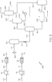
- FIG. 3 depicts another embodiment of a deasphalting process 103, in which the process further comprising an oil/water separator 220 and a water treatment unit 200 for treating the light fraction 184. It should be understood that the process of FIG. 3 may be in accordance with any of the embodiments previously described with reference to FIGS. 1 and 2 .
- FIG. 3 depicts a pressurized, heated hydrocarbon-based composition 124 that is combined with a pressurized, supercritical water stream 126 in a mixing device 130 to create a combined feed stream 132, which is fed into a supercritical upgrading reactor 150 to produce an upgraded reactor product 152.
- the product may be depressurized through a valve 170 to produce a depressurized stream 172, which is separated into at least a heavy fraction 182 and a light fraction 184 by a light-heavy separator 180.
- the deasphalting process 102 comprises an oil/water separator 220.
- the light fraction 184 is passed to the oil/water separator 220 which removes water from the light fraction 184 to produce a dewatered light fraction 224 and a water fraction 222.
- the water fraction 222 may be passed to a water treatment unit 200 and the dewatered light fraction 224 may be passed to a separation unit 240.
- the water treatment unit may treat the water fraction 222 through any known water treatment processes.
- the water treatment unit 200 may treat the water fraction 222 in accordance with any traditional water treatment steps, including filtering, deoiling, demineralizing, and adjusting the pH of the water fraction 222.
- the water treatment unit 200 may use physical processes, such as settling and filtration, chemical processes such as disinfection and coagulation, biological processes such as slow sand filtration, or any combination of these to treat the water fraction 222.
- the water treatment unit 200 may utilize chlorination, aeration, flocculation, polyelectrolytes, sedimentation, or other techniques known to purify water to treat water fraction 222.
- the water fraction 222 may undergo treatment to produce feed water. The feed water may be recycled and used in other processes or used to generate the supercritical water stream 126.
- the water treatment unit 200 may be in accordance with any known water treatment units known in the industry.
- the dewatered light fraction 224 may have a water content of less than or equal to 1 wt% water, such as less than or equal to 0.5 wt% water or less than or equal to 0.1 wt% water. In some embodiments, the dewatered light fraction 224 may have a water content such that the viscosity of the dewatered light fraction 224 is less than or equal to 380 centistokes (cSt), such as less than or equal to 180 cSt.
- cSt centistokes
- the dewatered light fraction 224 may be passed to a separation unit 240.
- the separation unit 240 may, in some embodiments, be a distillation unit or an aromatic separator.
- the separation unit 240 may separate the dewatered light fraction 224 into a gas fraction 244, a dewatered heavy oil fraction 242 and a dewatered paraffinic fraction 246.
- the separation unit 240 may have a temperature controller to control the temperature of the internal fluid in the separation unit 240.
- the dewatered paraffinic fraction 246 may be combined with the heavy fraction 182.
- the dewatered paraffinic fraction 246 may be combined with the heavy fraction 182 in an extractor 250.
- the extractor 250 may combine the dewatered paraffinic fraction 246 and the heavy fraction 182 to produce deasphalted oil 252 and asphaltene 256.
- the deasphalted oil 252 may be passed to a product tank 260.
- the dewatered heavy oil 242 may be combined with the deasphalted oil 252, such as in the product tank 260 shown in FIG. 3 .
- water may affect the agglomeration of asphaltene 256.
- water may enhance or prevent agglomeration depending on the conditions and the properties of the asphaltene 256.
- the asphaltene 256 may need to agglomerate to fully separate from maltene in the presence of the paraffinic solvent, such as the dewatered paraffinic fraction 246 and the paraffinic fraction 192.
- the heavy fraction 182 may only contain trace amounts of water, such as less than 2000 wt ppm.
- the heavy fraction 182 may contain less than 1000 wt ppm water, or less than 800 wt ppm water, or less than 500 wt ppm water, or less than 100 wt ppm water. This minimal concentration of water may not adversely affect the asphaltene 256 separation.
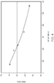
- FIG. 4 is a graph of the paraffinic volume percentage as compared to the cut end point of the fraction in degrees Celsius (°C).
- cut end point refers to the temperature bounds of a fraction based on the beginning and end points determined from a cumulative true boiling point curve.
- a true boiling point of less than 100°C may produce a paraffin vol% of from 68 vol% to 70 vol% and a true boiling point of less than 250°C may produce a paraffin vol% of greater than 60 vol%.
- the paraffinic fraction 192 and the light paraffinic fraction 212 may have a true boiling point of less than 250°C and may have a paraffin vol% of greater than 60 vol% to ensure proper solubility of asphaltene 256 from the heavy fraction 182.
- Example 1 The reaction conditions and constituent properties used in the process are listed in Table 1, listed both by name and by the reference number used in FIG. 3 .
- Example 1 is a process for deasphalting oil, a hydrocarbon-based (HC-based) composition (comp.) 105 was pressurized in a pump to create a pressurized (pres.) hydrocarbon-based composition 116 with a pressure of 26.9 MPa (3901 psig).
- a water stream 110 was also pressurized to form a pressurized water stream 118 to a pressure of 26.9 MPa (3901 psig).
- the pressurized hydrocarbon-based composition 116 was pre-heated from a temperature of 24°C to 150°C.
- the pressurized water stream 118 was also pre-heated from a temperature of 20°C to a temperature of 450°C to form a supercritical water stream 126.
- the supercritical water stream 126 and the pressurized, heated hydrocarbon-based composition 124 were mixed in a feed mixer to produce a combined feed stream 132, which was introduced to a supercritical upgrading reactor to generate an upgraded reactor product 152.
- the upgraded reactor product 152 pressure 26.9 MPa (3901 psig) was depressurized by a valve into depressurized stream 172 (pressure 0.014 MPa (2 psig).
- the depressurized stream 172 was fed to a light-heavy separator 180, a flash drum, to separate the depressurized stream 172 into a heavy fraction 182 and a light fraction 184.
- the light fraction 184 was then passed to an oil/water separator to separate the light fraction 184 into a dewatered light fraction 224 and a water fraction 222.
- the dewatered light fraction 224 was passed to a separation unit to produce a gas fraction 194, a dewatered paraffinic fraction 246 and a dewatered heavy oil fraction 242.
- the dewatered paraffinic fraction 246 was combined with the heavy fraction 182 in an extractor to produce a deasphalted oil fraction 252 and asphaltene 256.
- Example 1 was able to generate deasphalted oil without supplying external energy to the system, without supplying external solvents (such as external paraffins) to the system, and without the need for cooling and reheating the constituents.
- Example 1 consumed a minimal concentration of water and was able to recycle the water fraction 222.
- Example 1 was able to generate more fuel in a more efficient, self-sustaining system, saving time and money. Name Ref. No. HC-Based Comp.
- Table 1 shows the conditions, properties, and compositions of each of the listed components in the deasphalting process 103. It should be understood that some properties will not be applicable to all fractions, for instance, API and other petroleum properties do not apply to the water fraction 222 and the light fraction 184, which contains a majority of water (about 56.5%). Table 1 (Continued) Name Ref. No.
Description
- Embodiments of the present disclosure generally relate to systems and processes for deasphalting oil. Specifically, embodiments of the present disclosure relate to systems and processes for using hydrocarbon products to upgrade heavy oil.
- The steady increase in the need for refined products has led to a dependency on heavy crude oil to meet the rising demand. Heavy crude oils are available at a significant discount to light, sweet crudes (oils with low hydrogen sulfide and carbon dioxide contents, usually containing less than 0.5% sulfur) and can yield significantly more processable residue.
- However, heavy crude oils may contain impurities, and may have a metal content, sulfur content, or aromatic content that is unsuitable in some industrial applications. For these reasons, pretreatment steps to upgrade the heavier crude oil are usually required. The pretreatment methods can be classified into two main groups: solvent extraction, and hydroprocessing.
- An example of solvent extraction includes the ROSE® (Residuum Oil Supercritical Extraction) solvent extraction process, developed by Kellogg Brown & Root, Inc. The ROSE process is a solvent deasphalting (SDA) process that separates a resin fraction from asphaltene. However, the ROSE process demonstrates poor conversion of the vacuum residue and thereby is not an economically feasible process. Specifically, to reduce the metal content of the vacuum residue of Arabian heavy crude oil from 250 weight parts per million (wt ppm) to 9 wt ppm by the ROSE process, over 50% of vacuum residue is rejected as asphaltene pitch. Therefore, the ROSE process is not an effective deasphalting oil process because it rejects so much of the vacuum residue.
- Hydroprocessing reactions may also be utilized to reduce asphaltene using a supercritical water process. Hydroprocessing uses hydrogenation reactions in the presence of a catalyst and an external supply of hydrogen as a post-treatment process. However, a hydroprocessing unit requires a significant investment and consumes a considerable amount of externally-supplied hydrogen. Additionally, asphaltene present in oil may plug the pores of the catalyst, causing operational problems and increasing costs. Therefore, hydroprocessing is also an ineffective deasphalting oil process
-
US 4 591 426 A discloses a process for upgrading a hydrocarbon by hydroconversion, separation and solvent deasphalting. - Accordingly, a need exists for improved systems for upgrading and deasphalting heavy crude oil
- The present invention relates to methods for producing deashpalted oil as defined in claims 1 and 3.
- In accordance with one embodiment of the present disclosure, a process for producing deasphalted oil is provided. The process combines a supercritical water stream with a pressurized, heated hydrocarbon-based composition in a mixing device to create a combined feed stream. The combined feed stream is introduced to a supercritical reactor to produce an upgraded product. The supercritical reactor operates at a temperature greater than the critical temperature of water and a pressure greater than the critical pressure of water. The upgraded product is depressurized and separated into at least one light and one heavy fraction, where the heavy fraction has a greater concentration of asphaltene than the light fraction. The light fraction is passed to a separator and is separated into at least one gas fraction, one paraffinic fraction, and one water fraction. The at least one paraffinic fraction is combined with the heavy fraction to remove asphaltene and thereby produce deasphalted oil.
- In accordance with another embodiment of the present disclosure, another process for producing deasphalted oil is provided. The process combines a supercritical water stream with a pressurized, heated hydrocarbon-based composition in a mixing device to create a combined feed stream. The combined feed stream is introduced to a supercritical reactor to produce an upgraded product. The supercritical reactor operates at a temperature greater than the critical temperature of water and a pressure greater than the critical pressure of water. The upgraded product is depressurized and separated into at least one light and one heavy fraction, where the heavy fraction has a greater concentration of asphaltene than the light fraction. The light fraction is passed to an oil/water separator to produce a dewatered light fraction and a water fraction. The dewatered light fraction is passed to a distillation unit to separate it into at least one gas fraction, one dewatered paraffinic fraction, and one dewatered heavy oil fraction. The dewatered paraffinic fraction and the heavy oil fraction are combined to produce at least one deasphalted oil fraction.
- The following detailed description of specific embodiments of the present disclosure can be best understood when read in conjunction with the following drawings, in which:
-
FIG. 1 is a schematic view of a process for deasphalting oil, according to embodiments described; -
FIG. 2 is a schematic view of a process for deasphalting oil that includes an additional separating step, according to embodiments described; -
FIG. 3 is a schematic view of another process for deasphalting oil that includes an oil/water separator and a water treatment unit, according to embodiments described; and -
FIG. 4 is a graph of the paraffinic content of fractions based on distillation boiling point ranges. - Embodiments of the present disclosure are directed to processes for deasphalting oils. More specifically, embodiments of the present disclosure are directed to processes for utilizing supercritical water to upgrade and separate hydrocarbon-based compositions to produce deasphalted oil while removing or reducing the need for external solvents, such as external paraffinic solvents and external hydrogen.
- Specific embodiments will now be described with references to the figures. Whenever possible, the same reference numerals will be used throughout the drawings to refer to the same or like parts.
-
FIG. 1 schematically depicts adeasphalting process 101 in which supercritical water is used to remove or reduce the asphaltene content in heavy oil fractions. As used throughout the disclosure, "supercritical" refers to a substance at a pressure and a temperature greater than that of its critical pressure and temperature, such that distinct phases do not exist and the substance may exhibit the diffusion of a gas while dissolving materials like a liquid. As such, supercritical water is water having a temperature and pressure greater than the critical temperature and the critical pressure of water. At a temperature and pressure greater than the critical temperature and pressure, the liquid and gas phase boundary of water disappears, and the fluid has characteristics of both liquid and gaseous substances. Supercritical water is able to dissolve organic compounds like an organic solvent and has excellent diffusibility like a gas. Regulation of the temperature and pressure allows for continuous "tuning" of the properties of the supercritical water to be more liquid-like or more gas-like. Supercritical water has reduced density and lesser polarity, as compared to liquid-phase sub-critical water, thereby greatly extending the possible range of chemistry, which can be carried out in water. - Supercritical water has various unexpected properties as it reaches supercritical boundaries. Supercritical water has very high solubility toward organic compounds and has an infinite miscibility with gases. Furthermore, radical species can be stabilized by supercritical water through the cage effect (that is, a condition whereby one or more water molecules surrounds the radical species, which then prevents the radical species from interacting). Without being limited to theory, stabilization of radical species helps prevent inter-radical condensation and thereby reduces the overall coke production in the current embodiments. For example, coke production can be the result of the inter-radical condensation. In certain embodiments, supercritical water generates hydrogen gas through a steam reforming reaction and water-gas shift reaction, which is then available for the upgrading reactions.
- Moreover, the high temperature and high pressure of supercritical water may give water a density of 0.123 grams per milliliter (g/mL) at 27 MPa and 450°C. Contrastingly, if the pressure was reduced to produce superheated steam, for example, at 20 MPa and 450°C, the steam would have a density of 0.079 g/mL. Fluids having a closer density to hydrocarbons may have better dissolution power. Additionally, at that density, the hydrocarbons may interact with superheated steam to evaporate and mix into the liquid phase, leaving behind a heavy fraction that may generate coke upon heating. The formation of coke or coke precursor may plug the lines and must be removed. Therefore, supercritical water is superior to steam in some applications.
-
FIG. 1 depicts adeasphalting process 101 for producingdeasphalted oil 252 by utilizing asupercritical water stream 126. As a brief overview, thedeasphalting process 101 combines asupercritical water stream 126 and a pressurized, heated hydrocarbon-basedcomposition 124 in amixing device 130 to create a combinedfeed stream 132. The combinedfeed stream 132 is introduced to asupercritical upgrading reactor 150, which operates at a temperature greater than the critical temperature of water and a pressure greater than the critical pressure of water. Thesupercritical upgrading reactor 150 produces an upgradedreactor product 152 that is depressurized and separated into alight fraction 184 and aheavy fraction 182. Thelight fraction 184 is passed to a gas/oil/water separator 190 to separate thelight fraction 184 into agas fraction 194, aparaffinic fraction 192, and awater fraction 196. Theparaffinic fraction 192 is combined with theheavy fraction 182 to remove asphaltene from theheavy fraction 182 and thereby producedeasphalted oil 252. - As used throughout the disclosure, "asphaltene" refers to a hydrocarbon composition consisting primarily of carbon, hydrocarbon, nitrogen, oxygen and sulfur, with trace amounts of vanadium and nickel. Without being bound by theory, asphaltene refers to the portion of petroleum that is not dissolved in paraffin solvent (the dissolved portion is referred to as maltene). High boiling point fractions, such as vacuum residue, generally have large concentrations of asphaltene. As mentioned, in some embodiments, the combined
feed stream 132 may comprise vacuum residue, atmospheric residue, or combinations thereof. In some embodiments, a vacuum residue fraction may have a true boiling point (TBP) in which 10% of the fraction evaporates at temperatures of greater than or equal to 566°C (1050°F). - In some embodiments, the combined
feed stream 132 may have an asphaltene content, as measured using n-heptane of greater than 0.1 weight percent (wt%). While there are various definitions regarding what all constitutes asphaltene, it is generally accepted in the industry that n-heptane is an insoluble material that constitutes the majority of the asphaltene fraction. Thus, the asphaltene or n-heptane insoluble content was measured using the American Standard Testing Methodology (ASTM) Standard D3279. In some embodiments, the asphaltene content may be greater than 1 wt%, greater than 5 wt% or greater than 10 wt%. For instance, the asphaltene content in the combinedfeed stream 132 may be from 0.1 wt% to 1 wt%, or from 0.1 wt% to 3 wt%, or from 0.1 wt% to 5 wt%. The asphaltene content in the combinedfeed stream 132 may be from 1 wt% to 3 wt%, or from 1 wt% to 5 wt%, or from 3 wt% to 5 wt%. In some embodiments, the ratio of thesupercritical water stream 126 to the pressurized, heated hydrocarbon-basedcomposition 124 may be manipulated so as to produce an asphaltene content in the combinedfeed stream 132 of less than 5 wt%. In some embodiments it may be desirable to reduce the asphaltene content in the combinedfeed stream 132 to less than or equal to 5 wt% asphaltene to reduce the likelihood of coke formation. - Without intent to be bound by any particular theory, asphaltene may create processing problems, as it can precipitate in crude oil production pipelines, inhibiting pipeline flow. Additionally, asphaltene can also be easily converted to coke if subjected to high temperatures, which may be undesirable and problematic. Asphaltene is often used synonymously with pitch and bitumen; however, while pitch and bitumen contain asphaltene, they may additionally contain other fraction contaminants (such as maltene, a non-asphaltene fraction).
- Asphaltene typically includes aromatic cores attached to aliphatic carbon side chains. Without intent to be bound by any particular theory, the increased aromaticity of asphaltene may cause interaction with other aromatic compounds, including multi-ringed compounds. Aromatic bonds exhibit greater bond energy than aliphatic carbon-carbon bonds, and thus are harder to break. While use of supercritical water helps to suppress intermolecular reactions through caging effects, the aromatic moieties may be limited by reaction temperature constraints. Therefore, the side chains present in asphaltene may break away from the aromatic cores while the aromatic moieties remain intact. The aromatic moieties may begin to stack, forming multi-layered aromatic sheets, which may be converted to coke. As mentioned, coke is undesirable and may inhibit pipeline flow or create other processing concerns.
- Referring again to
FIG. 1 , in some embodiments, the hydrocarbon-basedcomposition 105 may comprise whole range crude oil, reduced crude oil, atmospheric distillates, atmospheric residue, vacuum distillates, vacuum residue, cracked product (such as light cycle oil or coker gas oil) or other refinery streams. The hydrocarbon-basedcomposition 105 may be any hydrocarbon source derived from petroleum, coal liquid, or biomaterials. Possible hydrocarbon sources for hydrocarbon-basedcomposition 105 may include whole range crude oil, distilled crude oil, reduced crude oil, residue oil, topped crude oil, product streams from oil refineries, product streams from steam cracking processes, liquefied coals, liquid products recovered from oil or tar sands, bitumen, oil shale, asphaltene, biomass hydrocarbons, and the like. In a specific embodiment, the hydrocarbon-basedcomposition 105 may include atmospheric residue, atmospheric distillates, vacuum gas oil (VGO), vacuum distillates, or vacuum residue. In some embodiments, the hydrocarbon-basedcomposition 105 may include combined streams from a refinery, produced oil, or other hydrocarbon streams from an upstream operation. The hydrocarbon-basedcomposition 105 may be decanted oil, oil containing 10 or more carbons (C10+ oil) or carbon streams from an ethylene plant. The hydrocarbon-basedcomposition 105 may, in some embodiments, be liquefied coal or biomaterial-derivatives such as bio-fuel oil. - The hydrocarbon-based
composition 105 may be pressurized in apump 112 to create a pressurized hydrocarbon-basedcomposition 116. The pressure of pressurized hydrocarbon-basedcomposition 116 may be at least 22.1 megapascals (MPa), which is approximately the critical pressure of water. Alternatively, the pressure of the pressurized hydrocarbon-basedcomposition 116 may be between 22.1 MPa and 35 MPa, such as between 23 MPa and 35 MPa or between 24 MPa and 30 MPa. In some embodiments, the pressure of the pressurized hydrocarbon-basedcomposition 116 may be from 24 MPa to 28 MPa, or from 26 MPa to 30 MPa, or from 25 MPa to 27 MPa. - As shown in
FIG. 1 , the pressurized hydrocarbon-basedcomposition 116 may be heated in one ormore petroleum pre-heaters 120 to form pressurized, heated hydrocarbon-basedcomposition 124. In some embodiments, the pressurized, heated hydrocarbon-basedcomposition 124 may have a pressure greater than the critical pressure of water, as described previously, and a temperature of less than or equal to 150°C. The temperature of the pressurized, heated hydrocarbon-basedcomposition 124 may be between 10°C and 150°C, or between 50°C and 150°C, or between 100°C and 150°C, or between 75°C and 150°C, or between 50°C and 100°C. Thepetroleum pre-heater 120 may be a natural gas fired heater, heat exchanger, an electric heater, or any type of heater known in the art. In some embodiments, the pressurized, heated hydrocarbon-basedcomposition 124 may be heated in a double pipe heat exchanger later in the process. - As shown in
FIG. 1 , thewater stream 110 may be any source of water, such as awater stream 110 having conductivity of less than 1 microsiemens (µS)/centimeters (cm). In some embodiments, thewater stream 110 may have a conductivity of less than 0.1 µS/cm or less than 0.05 µS/cm. Thewater stream 110 may also include demineralized water, distillated water, boiler feed water, and deionized water. In at least one embodiment,water stream 110 is a boiler feed water (BFW) stream. InFIG. 1 ,water stream 110 is pressurized bypump 114 to producepressurized water stream 118. The pressure of thepressurized water stream 118 is at least 22.1 MPa, which is approximately the critical pressure of water. The pressure of thepressurized water stream 118 may be from 22.1 MPa to 35 MPa, such as between 23 MPa and 35 MPa or between 24 MPa and 30 MPa. In some embodiments, the pressure of thepressurized water stream 118 may be from 24 MPa to 28 MPa, or from 26 MPa to 30 MPa, or from 25 MPa to 27 MPa. - In
FIG. 1 , thepressurized water stream 118 may then be heated in awater pre-heater 122 to create asupercritical water stream 126. The temperature of thesupercritical water stream 126 is greater than 374°C, which is approximately the critical temperature of water. Alternatively, the temperature of thesupercritical water stream 126 may be greater than 380°C. In some embodiments, the temperature may be between 380°C and 600°C, or between 400°C and 550°C, or between 380°C and 500°C, or between 400°C and 500°C, or between 380°C and 450°C. - Similar to the
petroleum pre-heater 120, suitable water pre-heaters 122 may include a natural gas fired heater, a heat exchanger, and an electric heater. Thewater pre-heater 122 may be a unit separate and independent from thepetroleum pre-heater 120. - Referring again to
FIG. 1 , thesupercritical water stream 126 and the pressurized, heated hydrocarbon-basedcomposition 124 may be mixed in a feedmixer mixing device 130 to produce a combinedfeed stream 132. Themixing device 130 can be any type of mixing device capable of mixing thesupercritical water stream 126 and the pressurized, heated hydrocarbon-basedcomposition 124. In one embodiment, themixing device 130 may be a mixing tee. The volumetric flow ratio of supercritical water to hydrocarbons fed to the feed mixer may vary. In one embodiment, the volumetric flow ratio may be from 10:1 to 1:10, or 5:1 to 1:5, or 1:1 to 4:1 at standard ambient temperature and pressure (SATP). - In
FIG. 1 , the combinedfeed stream 132 may then be introduced to asupercritical upgrading reactor 150 configured to upgrade the combinedfeed stream 132. Thesupercritical upgrading reactor 150 may be an upflow, downflow, or horizontal flow reactor. An upflow, downflow or horizontal reactor refers to the direction the supercritical water and petroleum-based composition flow through thesupercritical upgrading reactor 150. An upflow, downflow, or horizontal flow reactor may be chosen based on the desired application and system configuration. Without intending to be bound by any theory, in downflow supercritical reactors, heavy hydrocarbon fractions may flow very quickly due to having a greater density, which may result in shortened residence times (known as channeling). This may hinder upgrading, as there is less time for reactions to occur. Upflow supercritical reactors have an increased residence time, but may experience difficulties due to large particles, such as carbon-containing compounds in the heavy fractions, accumulating in the bottom of the reactor. This accumulation may hinder the upgrading process and plug the reactor. Upflow reactors typically utilize catalysts to provide increased contact with the reactants; however, the catalysts may break down due to the harsh conditions of supercritical water, forming insoluble aggregates, which may generate coke. Horizontal reactors may be useful in applications that desire phase separation or that seek to reduce pressure drop, however; the separation achieved may be limited. Each type of reactor flow has positive and negative attributes that vary based on the applicable process. - In
FIG. 1 , the combinedfeed stream 132 is introduced through an inlet port of thesupercritical upgrading reactor 150. In some embodiments, the combinedfeed stream 132 may be introduced through an inlet port at the top of thesupercritical upgrading reactor 150, at the bottom, or at a side wall in thesupercritical upgrading reactor 150, depending on the flow direction, as previously discussed. - The
supercritical upgrading reactor 150 may, in some embodiments, be an isothermal or non-isothermal reactor. The reactor may be a tubular-type vertical reactor, a tubular-type horizontal reactor, a vessel-type reactor, a tank-type reactor having an internal mixing device, such as an agitator, or a combination of any of these reactors. Moreover, additional components, such as a stirring rod or agitation device may also be included in thesupercritical upgrading reactor 150. - The
supercritical upgrading reactor 150 may operate at a temperature greater than the critical temperature of water and a pressure greater than the critical pressure of water. In one or more embodiments, thesupercritical upgrading reactor 150 may have a temperature of between 380°C to 480°C, or between 390°C to 450°C. - The
supercritical upgrading reactor 150 may have dimensions defined by the equation L/D, where L is a length of thesupercritical upgrading reactor 150 and D is the diameter of thesupercritical upgrading reactor 150. In one or more embodiments, the L/D value of thesupercritical upgrading reactor 150 may be sufficient to achieve a superficial velocity of fluid greater than 0.5 meter (m)/minute (min), or an L/D value sufficient to achieve a superficial velocity of fluid between 1 m/min and 5 m/min. The fluid flow may be defined by a Reynolds number greater than 5000. - In some embodiments, the residence time of the internal fluid in the
supercritical upgrading reactor 150 may be longer than 5 seconds, such as longer than 1 minute. In some embodiments, the residence time of the internal fluid in thesupercritical upgrading reactor 150 may be between 2 and 30 minutes, such as between 2 and 20 minutes or between 5 and 15 minutes or between 5 and 10 minutes. - Referring to
FIG. 1 , upon exiting the reactor, the pressure of the upgradedreactor product 152 of thesupercritical upgrading reactor 150 may be reduced to create a depressurizedstream 172, which may have a pressure from 0.05 MPa to 2.2 MPa. The depressurizing can be achieved by many devices, for example, avalve 170 as shown inFIG. 1 . Optionally, the upgradedreactor product 152 may be cooled to a temperature less than 200°C in a cooler (not shown) upstream of thevalve 170. Various cooling devices are contemplated for the cooler, such as a heat exchanger. - The depressurized
stream 172 may then be fed to a light-heavy separator 180 to separate the depressurizedstream 172 into aheavy fraction 182 and alight fraction 184. Various light-heavy separators 180 are contemplated, for example, in some embodiments the light-heavy separator 180 may be a flash drum or distillation unit. In some embodiments, the light-heavy separator 180 may have a temperature controller to control the temperature of the internal fluid comprising the depressurizedstream 172. In some embodiments, the temperature controller may be an off-shelf controller. In some embodiments, the light-heavy separator 180 may be a flash drum, which may have a temperature of from 200°C to 250°C and a pressure of about 1 atmosphere (ATM). - In some embodiments, the hydrocarbons in the
light fraction 184 may have an American Petroleum Institute (API) gravity value that is greater than that of theheavy fraction 182. API gravity is a measure of how heavy or light a petroleum liquid is when compared to water based on the density relative to water (also known as specific gravity). API gravity can be calculated in accordance with Equation 1: - API Gravity = 141.5 / ((Specific gravity at 60°F) - 131.5) EQUATION 1
- API gravity is a dimensionless quantity that is referred to by degrees, with most petroleum liquids falling between 10° and 70°. In some embodiments, the hydrocarbons in the
light fraction 184 may have an API gravity value of greater than or to 30°. The hydrocarbons in thelight fraction 184 may have an API gravity value from 30° to 40°, 30° to 45°, or from 30° to 50° or from 30° to 70°. In some embodiments, the hydrocarbons in thelight fraction 184 may have an API value of greater than or equal to 31°, such as 31.1° In some embodiments, the hydrocarbons in thelight fraction 184 may have an API value of from 40° to 45°, which may be very commercially desirable. In some embodiments, it may be desirable that the hydrocarbons in thelight fraction 184 has an API value of less than 45°, as when the API value is greater than 45° the molecular chains may become shorter and the hydrocarbons in thelight fraction 184 may be commercially less valuable. - The hydrocarbons in the
heavy fraction 182 may have an API gravity value of less than or equal to 30°. For instance, the hydrocarbons in theheavy fraction 182 may have an API gravity value of less than 30° and greater than or equal to 20°. The hydrocarbons in theheavy fraction 182 may have an API gravity value from 22.3° to 30°, or may have an API value of less than 22.3°, such as a value between 10° and 22.3°, or between 10° and 30°. In some embodiments, the hydrocarbons in theheavy fraction 182 may have an API value of less than 10°, such as from 5° to 30° or 1° to 30°, which may be considered "extra" heavy, as oil with an API value of less than 10° sinks in water. - In some embodiments, the true boiling point (TBP) of 80% of the hydrocarbons in the
light fraction 184 may be less than 250°C, such as between 100°C and 250°C. This boiling point range may allow for a greater concentration of paraffins to be present in the hydrocarbons in thelight fraction 184. In some embodiments, the TBP of 90% of the hydrocarbons in thelight fraction 184 may be less than 250°C, such as between 100°C and 250°C or between 150°C and 250°C. - The hydrocarbons in the
heavy fraction 182 may have a greater concentration of asphaltene than those in thelight fraction 184. In some embodiments, the hydrocarbons inheavy fraction 182 may have at least 25% more asphaltene than those in thelight fraction 184, or may have at least 30%, at least 50%, or at least 75% more asphaltene than those in thelight fraction 184. The hydrocarbons in theheavy fraction 182 may have at least 100% or at least 200% or at least 300% or even at least 500% more asphaltene than those in thelight fraction 184. The amount of asphaltene in the hydrocarbons in thelight fraction 184 and the hydrocarbons in theheavy fraction 182 depends on the content of the combinedfeed stream 132. In general, the asphaltene content as measured by the content of n-heptane insoluble fraction in the combinedfeed stream 132 should be greater than 0.1 wt%, or greater than 1 wt%, or greater than 5 wt%, as previously discussed. In general, the amount of asphaltene in the hydrocarbons in the combinedfeed stream 132 may be about 1 wt% when using Arabian Light Crude Oil and may be about 26 wt% when using vacuum residue from Maya Crude Oil. - In some embodiments, the
heavy fraction 182 may have a water content of less than or equal to 5 wt%, such as less than or equal to 3 wt%, or less than or equal to 1 wt%, or less than or equal to 0.1 wt%. Theheavy fraction 182 may be dewatered in some embodiments. - Referring again to
FIG. 1 , thelight fraction 184 may be passed to a gas/oil/water separator 190. The gas/oil/water separator 190 may separate thelight fraction 184 into agas fraction 194, aparaffinic fraction 192, and awater fraction 196. In some embodiments, theparaffinic fraction 192 may be combined with theheavy fraction 182 to removeasphaltene 256 and thereby producedeasphalted oil 252. - The
gas fraction 194 may be further passed to a caustic treatment unit (not pictured) to remove contaminants, such as hydrogen sulfide (H2S) or mercaptans (R-SH). In some embodiments, thegas fraction 194 may be processed by a caustic treatment unit to produce fuel gas (not pictured). In some embodiments, the caustic treatment unit may use lye, such as sodium hydroxide, to reduce the content of sulfur and other unwanted contaminants present in thegas fraction 194. As used throughout the disclosure, "lye" refers to a strong alkaline solution, such as sodium hydroxide or potassium hydroxide. Hydrogen sulfide is a deadly odorous gas that may be generated during deasphalting processes, such as thedeasphalting process 101. Without being bound by any particular theory, hydrogen sulfide may readily dissolve in caustic solutions due to its solubility in high pH conditions, such as a pH of greater than or equal to 10, or from 10 to 12. - As shown in
FIG. 1 , theparaffinic fraction 192 may be passed to anextractor 250. Theextractor 250 may utilize theparaffinic fraction 192 to separatedeasphalted oil 252 andasphaltene 256 from theheavy fraction 182. In some embodiments, the process may produceasphaltene 256 at a rate of 14 kilograms per hour (kg/hr). Asphaltene may be produced at a rate of from 10 to 15 kg/hr, or from 12 to 15 kg/hr, or from 15 to 20 kg/hr, or from 15 to 30 kg/hr. - The
extractor 250 may be any suitable extractor known in the industry. In some embodiments, theextractor 250 may have a temperature controller to control the temperature of the internal fluid. In some embodiments, theextractor 250 may have a temperature controller to maintain the temperature of the internal fluid such that theparaffinic fraction 192 exists in a liquid phase. In some embodiments, theextractor 250 may have an internal fluid temperature of from 50°C to 250°. Theextractor 250 may have an internal fluid temperature of from 50°C to 120°C, or from 75°C to 120°C, or from 100°C to 200°C, or from 50°C to 200°C. The temperature controller may be used to maintain the internal fluid temperature within a suitable range, such as from 50°C to 250°C, as mentioned. - In some embodiments, the
extractor 250 may have an internal mixing device. The internal mixing device may be any suitable mixing device. In some embodiments, the internal mixing device may be a rotating agitator, such as a rotating agitator having anchor-type blades. The agitator may further encourage a reaction between theparaffinic fraction 192 and theheavy fraction 182 to producedeasphalted oil 252 andasphaltene 256. - Additionally, to encourage the reaction, in some embodiments the
paraffinic fraction 192 and theheavy fraction 182 may have a residence time in theextractor 250 of from 1 minute to 8 hours. In some embodiments, theparaffinic fraction 192 and theheavy fraction 182 may have a residence time in theextractor 250 of at least 10 minutes to allow theparaffinic fraction 192 to act as a solvent, reacting with theheavy fraction 182 to producedeasphalted oil 252. If the asphaltene in theheavy fraction 182 has already precipitated following the light-heavy separation step (which may be caused by a high concentration of paraffins in the light fraction 184), the residence time in the extractor may need to be at least 10 minutes to allow theparaffinic fraction 192 to upgrade theheavy fraction 182 and producedeasphalted oil 252. In some embodiments, the residence time may be from 10 minutes to 30 minutes or from 10 minutes to 60 minutes. In some embodiments, theextractor 250 may have a residence time of from 10 minutes to 45 minutes, or from 10 minutes to 8 hours. Theextractor 250 may have a residence time of at least 15 minutes, at least 20 minutes, at 30 minutes, at least 45 minutes, or at least 1 hour. - Without being bound by theory, the
supercritical upgrading reactor 150 may crack long paraffin chains attached to aromatics present in the combinedfeed stream 132 to produce short paraffin chains and aromatic compounds. As used throughout, "long paraffin chain" refers to a hydrocarbon chain comprising greater than or equal to 12 carbons. As used throughout, "short paraffin chain" refers to a hydrocarbon chain comprising less than or equal to 11 carbons. Long paraffin chain compounds may have a boiling point higher than 210°C (such as C12H26, which has a boiling point of about 212°C) and may have a melting point below 0°C (C12H26 has a melting point of -10°C). - In some embodiments, the
paraffinic fraction 192 may contain a concentration of at least 50 percent by volume (vol%) short chain paraffins. In some embodiments, theparaffinic fraction 192 may contain more than 50 vol% of paraffins. In some embodiments, theparaffinic fraction 192 may contain more than 60 vol% paraffins, such as more than 70 vol%, more than 75 vol%, more than 80 vol%, or more than 90 vol%. Theparaffinic fraction 192 may contain from 60 vol% to 100 vol% paraffins, or from 50 vol% to 100 vol% paraffins. Theparaffinic fraction 192 may be used as a solvent to remove asphaltene from theheavy fraction 182. Therefore, in some embodiments, a greater paraffin concentration in theparaffinic fraction 192 may lead to better asphaltene separation. A greater paraffin concentration in theparaffinic fraction 192 may lead to the production of moredeasphalted oil 252 from theheavy fraction 182, resulting in a more efficient process. - Referring now to
FIG. 2 , anotherdeasphalting process 102 is depicted. InFIG. 2 , theparaffinic fraction 192 is further processed by adistillation unit 210. It should be understood that the process ofFIG. 2 may be in accordance with any of the embodiments previously described with reference toFIG. 1 . LikeFIG. 1 ,FIG. 2 depicts a pressurized, heated hydrocarbon-basedcomposition 124 that is combined with a pressurized,supercritical water stream 126 in amixing device 130 to create a combinedfeed stream 132, which is fed into asupercritical upgrading reactor 150 to produce an upgradedreactor product 152. The product may be depressurized through avalve 170 to produce a depressurizedstream 172, which is separated into at least aheavy fraction 182 and alight fraction 184 by a light-heavy separator 180. Thelight fraction 184 may be passed to a gas/oil/water separator 190 to separate thelight fraction 184 into agas fraction 194, aparaffinic fraction 192, and awater fraction 196. The gas/oil/water separator 190 may be any separator known in the industry. In some embodiments, the gas/oil/water separator 190 may have a long chamber with multiple outlets to allow for an increased residence time for input fluid so as to allow more separation. In some embodiments, a demulsifier may be added to the gas/oil/water separator 190 to accelerate separation. - In
FIG. 2 , theparaffinic fraction 192 may be passed to adistillation unit 210 to produce at least a lightparaffinic fraction 212 and a heavyparaffinic fraction 216. The lightparaffinic fraction 212 may then be combined with theheavy fraction 182 in anextractor 250, as previously discussed, to producedeasphalted oil 252 andasphaltene 256. The lightparaffinic fraction 212 may have an increased concentration of paraffins, which may make the lightparaffinic fraction 212 more effective as a deasphalting solvent. The lightparaffinic fraction 212 may comprise at least 80 vol% paraffins, at least 85 vol% paraffins, at least 90 vol% paraffins, or at least 95 vol% paraffins. In the invention, the lightparaffinic fraction 212 has a TBP of 80% of the lightparaffinic fraction 212 of less than 200°C, less than 150°C, or less than 100°C. Without being bound by theory, removing the aromatic compounds from the lightparaffinic fraction 212 may allow the lightparaffinic fraction 212 to be a more efficient solvent to convert more of theheavy fraction 182 intodeasphalted oil 252. Thedistillation unit 210 may be in accordance with any distillation units known in the industry. -
FIG. 3 depicts another embodiment of adeasphalting process 103, in which the process further comprising an oil/water separator 220 and awater treatment unit 200 for treating thelight fraction 184. It should be understood that the process ofFIG. 3 may be in accordance with any of the embodiments previously described with reference toFIGS. 1 and2 . LikeFIGS. 1 and2 ,FIG. 3 depicts a pressurized, heated hydrocarbon-basedcomposition 124 that is combined with a pressurized,supercritical water stream 126 in amixing device 130 to create a combinedfeed stream 132, which is fed into asupercritical upgrading reactor 150 to produce an upgradedreactor product 152. The product may be depressurized through avalve 170 to produce a depressurizedstream 172, which is separated into at least aheavy fraction 182 and alight fraction 184 by a light-heavy separator 180. - In
FIG. 3 , thedeasphalting process 102 comprises an oil/water separator 220. InFIG. 3 , thelight fraction 184 is passed to the oil/water separator 220 which removes water from thelight fraction 184 to produce a dewateredlight fraction 224 and awater fraction 222. Thewater fraction 222 may be passed to awater treatment unit 200 and the dewateredlight fraction 224 may be passed to aseparation unit 240. - The water treatment unit may treat the
water fraction 222 through any known water treatment processes. Thewater treatment unit 200 may treat thewater fraction 222 in accordance with any traditional water treatment steps, including filtering, deoiling, demineralizing, and adjusting the pH of thewater fraction 222. In some embodiments, thewater treatment unit 200 may use physical processes, such as settling and filtration, chemical processes such as disinfection and coagulation, biological processes such as slow sand filtration, or any combination of these to treat thewater fraction 222. Moreover, thewater treatment unit 200 may utilize chlorination, aeration, flocculation, polyelectrolytes, sedimentation, or other techniques known to purify water to treatwater fraction 222. In some embodiments, thewater fraction 222 may undergo treatment to produce feed water. The feed water may be recycled and used in other processes or used to generate thesupercritical water stream 126. Thewater treatment unit 200 may be in accordance with any known water treatment units known in the industry. - The dewatered
light fraction 224 may have a water content of less than or equal to 1 wt% water, such as less than or equal to 0.5 wt% water or less than or equal to 0.1 wt% water. In some embodiments, the dewateredlight fraction 224 may have a water content such that the viscosity of the dewateredlight fraction 224 is less than or equal to 380 centistokes (cSt), such as less than or equal to 180 cSt. - As shown in
FIG. 3 , the dewateredlight fraction 224 may be passed to aseparation unit 240. Theseparation unit 240 may, in some embodiments, be a distillation unit or an aromatic separator. In some embodiments, theseparation unit 240 may separate the dewateredlight fraction 224 into agas fraction 244, a dewateredheavy oil fraction 242 and a dewateredparaffinic fraction 246. Theseparation unit 240 may have a temperature controller to control the temperature of the internal fluid in theseparation unit 240. - The dewatered
paraffinic fraction 246 may be combined with theheavy fraction 182. In some embodiments, the dewateredparaffinic fraction 246 may be combined with theheavy fraction 182 in anextractor 250. Theextractor 250 may combine the dewateredparaffinic fraction 246 and theheavy fraction 182 to producedeasphalted oil 252 andasphaltene 256. Thedeasphalted oil 252 may be passed to aproduct tank 260. Additionally, the dewateredheavy oil 242 may be combined with thedeasphalted oil 252, such as in theproduct tank 260 shown inFIG. 3 . - Without being bound by theory, water, as a polar compound, may affect the agglomeration of
asphaltene 256. In some embodiments, water may enhance or prevent agglomeration depending on the conditions and the properties of theasphaltene 256. Theasphaltene 256 may need to agglomerate to fully separate from maltene in the presence of the paraffinic solvent, such as the dewateredparaffinic fraction 246 and theparaffinic fraction 192. Theheavy fraction 182, as previously mentioned, may only contain trace amounts of water, such as less than 2000 wt ppm. In some embodiments, theheavy fraction 182 may contain less than 1000 wt ppm water, or less than 800 wt ppm water, or less than 500 wt ppm water, or less than 100 wt ppm water. This minimal concentration of water may not adversely affect theasphaltene 256 separation. -
FIG. 4 is a graph of the paraffinic volume percentage as compared to the cut end point of the fraction in degrees Celsius (°C). As used throughout, "cut end point" refers to the temperature bounds of a fraction based on the beginning and end points determined from a cumulative true boiling point curve. - As shown in
FIG. 4 , a true boiling point of less than 100°C may produce a paraffin vol% of from 68 vol% to 70 vol% and a true boiling point of less than 250°C may produce a paraffin vol% of greater than 60 vol%. As previously discussed, theparaffinic fraction 192 and the lightparaffinic fraction 212 may have a true boiling point of less than 250°C and may have a paraffin vol% of greater than 60 vol% to ensure proper solubility ofasphaltene 256 from theheavy fraction 182. - The following examples illustrate one or more embodiments of the present disclosure as previously discussed. The description of the embodiments is illustrative in nature and is in no way intended to be limiting it its application or use.
- The following simulation examples illustrate one or more embodiments of the present disclosure previously discussed. Specifically, a simulation, Example 1, was carried out in accordance with the previously described embodiments, particularly with respect to the embodiment of the
deasphalting process 103 depicted inFIG. 3 . The reaction conditions and constituent properties used in the process are listed in Table 1, listed both by name and by the reference number used inFIG. 3 . - Example 1 is a process for deasphalting oil, a hydrocarbon-based (HC-based) composition (comp.) 105 was pressurized in a pump to create a pressurized (pres.) hydrocarbon-based
composition 116 with a pressure of 26.9 MPa (3901 psig). Awater stream 110 was also pressurized to form apressurized water stream 118 to a pressure of 26.9 MPa (3901 psig). The pressurized hydrocarbon-basedcomposition 116 was pre-heated from a temperature of 24°C to 150°C. Thepressurized water stream 118 was also pre-heated from a temperature of 20°C to a temperature of 450°C to form asupercritical water stream 126. Thesupercritical water stream 126 and the pressurized, heated hydrocarbon-basedcomposition 124 were mixed in a feed mixer to produce a combinedfeed stream 132, which was introduced to a supercritical upgrading reactor to generate an upgradedreactor product 152. The upgraded reactor product 152 (pressure 26.9 MPa (3901 psig) was depressurized by a valve into depressurized stream 172 (pressure 0.014 MPa (2 psig). The depressurizedstream 172 was fed to a light-heavy separator 180, a flash drum, to separate the depressurizedstream 172 into aheavy fraction 182 and alight fraction 184. - The
light fraction 184 was then passed to an oil/water separator to separate thelight fraction 184 into a dewateredlight fraction 224 and awater fraction 222. The dewateredlight fraction 224 was passed to a separation unit to produce agas fraction 194, a dewateredparaffinic fraction 246 and a dewateredheavy oil fraction 242. The dewateredparaffinic fraction 246 was combined with theheavy fraction 182 in an extractor to produce adeasphalted oil fraction 252 andasphaltene 256. - Notably, Example 1 was able to generate deasphalted oil without supplying external energy to the system, without supplying external solvents (such as external paraffins) to the system, and without the need for cooling and reheating the constituents. Example 1 consumed a minimal concentration of water and was able to recycle the
water fraction 222. By utilizing so many upgraded, separated components of the combinedfeed stream 132, Example 1 was able to generate more fuel in a more efficient, self-sustaining system, saving time and money.

Name Ref. No. HC-Based Comp. 105 Light Fraction 184 Heavy Fraction 182 Dewatered Light Fraction 224 Water Fraction 222 Gas Fraction 244 Temperature [°C] 25 270 270 30 30 921 Pressure [psig] 0 2 2 2 2 1 Mass Flow [kg/h] 600 1170 91 513 657 10 Liquid Volume Flow [m3/h] 0.66 1.41 0.10 0.75 0.66 0.13 Petroleum Property (API) 23.9 N/A 21.3 75 N/A N/A Petroleum Property (TBP 5%) 315 N/A 372 N/A N/A N/A Petroleum Property (TBP 10%) 363 N/A 387 N/A N/A N/A Petroleum Property (TBP 30%) 375 N/A 447 N/A N/A N/A Petroleum Property (TBP 50%) 413 N/A 564 200 N/A N/A Petroleum Property (TBP 70%) 450 N/A 567 370 N/A N/A Petroleum Property (TBP 90%) 568 N/A 583 411 N/A N/A Petroleum Property (Sulfur wt%) 2.8 N/A 2.1 1.1 N/A 1.3 Petroleum Property (Paraffins by Volume) 19 N/A 18 58 N/A N/A Petroleum Property (Naphthenes by Volume) 40 N/A 47 21 N/A N/A Petroleum Property (Aromatics by Volume) 40 N/A 34 18 N/A N/A Water Content (wt%) - 56.5 0.1 0.7 99.5 - C7-Asphalthene (wt%) 2.5 - 2.5 - - - - Table 1 shows the conditions, properties, and compositions of each of the listed components in the
deasphalting process 103. It should be understood that some properties will not be applicable to all fractions, for instance, API and other petroleum properties do not apply to thewater fraction 222 and thelight fraction 184, which contains a majority of water (about 56.5%).Table 1 (Continued) Name Ref. No. Dewatered Paraffinic Fraction 246Dewatered Heavy Oil and Deparaffinated Light Oil 242Deasphalted Oil 252Dewatered Heavy Fraction 242 andDeasphalted Oil 252 Combined ProductTemperature [°C] 20 20 20 20 Pressure [psig] 1 1 1 1 Mass Flow [kg/h] 48 411 125 536 Liquid Volume Flow [m3/h] 0.07 0.55 0.15 0.70 Petroleum Property (API) 65.7 56.8 26.2 32.1 Petroleum Property (TBP 5%) N/A N/A 314 -- Petroleum Property (TBP 10%) N/A N/A 342 157 Petroleum Property (TBP 30%) 27 173 405 203 Petroleum Property ( TBP 50%)86 363 417 370 Petroleum Property ( TBP 70%)107 377 463 383 Petroleum Property (TBP 90%) 112 434 508 429 Petroleum Property (Sulfur wt%) 0.1 1.2 1.0 1.1 Petroleum Property (Paraffins by Volume) 83 40 23 42 Petroleum Property (Naphthenes by Volume) 12 35 45 34 Petroleum Property (Aromatics by Volume) 5 25 32 24 Water Content (wt%) <0.1 0.9 <0.1 C7-Asphalthene (wt%) 0 0 0.1 -- - As noted in the headings listed in Table 1, some components were sampled and tested after further processing or combining. For instance, a portion of the Dewatered
Heavy Oil Stream 242 was deparaffinated into a light oil stream. Similarly, a portion of the DewateredHeavy Oil Stream 242 was combined with theDeasphalted Oil Stream 252 to produce a Combined Product. The properties of the Light Oil and Combined Product are shown in Table 1.
Claims (13)
- A process for producing deasphalted oil, the process comprising:combining a supercritical water stream with a pressurized, heated hydrocarbon-based composition in a mixing device to create a combined feed stream;introducing the combined feed stream into a supercritical reactor, where the supercritical reactor operates at a temperature greater than a critical temperature of water and a pressure greater than a critical pressure of water, to produce an upgraded product;depressurizing the upgraded product;separating the depressurized upgraded product into at least one light and at least one heavy fraction, in which the heavy fraction has a greater concentration of asphaltene than the light fraction;passing the light fraction to a separator to separate the light fraction into at least one gas fraction, one paraffinic fraction, and one water fraction;passing the paraffinic fraction to a distillation unit to produce at least a light paraffinic fraction and a heavy paraffinic fraction, where a true boiling point of 80% of the light paraffinic fraction is less than 200 °C, preferably less than 150 °C; andcombining the light paraffinic fraction with the heavy fraction to remove asphaltene and thereby produce deasphalted oil.
- The process of claim 1, where combining the light paraffinic fraction and the heavy fraction is performed using an extractor, preferably where the extractor comprises a temperature controller to control the temperature of an internal fluid to a temperature of from 50°C to 250°C.
- A process for producing deasphalted oil comprising:combining a supercritical water stream with a pressurized, heated hydrocarbon-based composition in a mixing device to create a combined feed stream;introducing the combined feed stream into a supercritical reactor, where the supercritical reactor operates at a temperature greater than a critical temperature of water and a pressure greater than a critical pressure of water, to produce an upgraded product;depressurizing the upgraded product;separating the depressurized upgraded product into at least one light and at least one heavy fraction, where the heavy fraction has a greater concentration of asphaltene than the light fraction;passing the light fraction to an oil/water separator to produce a dewatered light fraction and a water fraction;passing the dewatered light fraction to a distillation unit to separate the dewatered light fraction into at least one gas fraction, one dewatered paraffinic fraction, and one dewatered heavy oil fraction, where a true boiling point of 80% of the dewatered paraffinic fraction is less than 200 °C, preferably less than 150 °C; andcombining the dewatered paraffinic fraction with the heavy fraction to produce at least one deasphalted oil fraction.
- The process of claim 3, where the dewatered light fraction has a water content of less than or equal to 1 wt% water.
- The process of claim 3 or claim 4 where the dewatered light fraction has a viscosity of less than or equal to 380 centistokes (cSt).
- The process ofany preceding claim, further comprising passing the water fraction to a water treatment unit to produce a feed water fraction.
- The process of any of claims 3 to 6, where the dewatered paraffinic fraction and the heavy fraction are combined in an extractor, preferably where the extractor comprises a temperature controller to control the temperature of an internal fluid to a temperature of from 50°C to 250°C.
- The process of any of claims 3 to 7, where the deasphalted fraction is passed to a product tank and combined with the dewatered heavy oil fraction to produce an oil product.
- The process of any preceding claim, where hydrocarbons in the light fraction have an American Petroleum Institute (API) gravity value that is greater than hydrocarbons in the heavy fraction.
- The process of any preceding claim, where hydrocarbons in the light fraction have an API gravity value of greater than or equal to 30° and hydrocarbons in the heavy fraction have an API gravity value of less than 30°.
- The process of any preceding claim, where the heavy fraction has at least a 25% or at least a 75% greater concentration of asphaltene than the light fraction.
- The process of any preceding claim, where separating the depressurized upgraded product comprises passing the depressurized upgraded product to at least one distillation unit or flash drum.
- The process of any preceding claim, where the gas fraction is passed to a caustic treatment unit to produce fuel gas.
Applications Claiming Priority (2)
| Application Number | Priority Date | Filing Date | Title |
|---|---|---|---|
| US201762442072P | 2017-01-04 | 2017-01-04 | |
| PCT/US2018/012027 WO2018128961A1 (en) | 2017-01-04 | 2018-01-02 | Systems and processes for deasphalting oil |
Publications (2)
| Publication Number | Publication Date |
|---|---|
| EP3565871A1 EP3565871A1 (en) | 2019-11-13 |
| EP3565871B1 true EP3565871B1 (en) | 2021-03-10 |
Family
ID=61007881
Family Applications (1)
| Application Number | Title | Priority Date | Filing Date |
|---|---|---|---|
| EP18700959.2A Active EP3565871B1 (en) | 2017-01-04 | 2018-01-02 | Processes for deasphalting oil |
Country Status (7)
| Country | Link |
|---|---|
| US (1) | US10577546B2 (en) |
| EP (1) | EP3565871B1 (en) |
| JP (1) | JP6980787B2 (en) |
| KR (1) | KR20190103301A (en) |
| CN (1) | CN110114442A (en) |
| SA (1) | SA519402062B1 (en) |
| WO (1) | WO2018128961A1 (en) |
Families Citing this family (8)
| Publication number | Priority date | Publication date | Assignee | Title |
|---|---|---|---|---|
| US11034897B1 (en) * | 2020-04-30 | 2021-06-15 | Saudi Arabian Oil Company | Scheme for supercritical water process for heavy oil upgrading |
| US11390816B2 (en) | 2020-06-16 | 2022-07-19 | Saudi Arabian Oil Company | Process to improve the stability of thermally cracked petroleum products |
| US11345861B2 (en) * | 2020-06-22 | 2022-05-31 | Saudi Arabian Oil Company | Production of linear olefins from heavy oil |
| US11319496B2 (en) * | 2020-07-02 | 2022-05-03 | Saudi Arabian Oil Company | Systems and processes for hydrocarbon blending |
| CN112239700B (en) * | 2020-10-23 | 2022-06-07 | 泉州市欧美润滑油制品有限公司 | Device and method for efficiently processing long-service-life high-definition high-pressure hydraulic oil |
| US20220220396A1 (en) * | 2021-01-06 | 2022-07-14 | Saudi Arabian Oil Company | Systems and processes for hydrocarbon upgrading |
| US11926801B2 (en) | 2021-01-28 | 2024-03-12 | Saudi Arabian Oil Company | Processes and systems for producing upgraded product from residue |
| CN113801690B (en) * | 2021-09-10 | 2023-01-03 | 中海油天津化工研究设计院有限公司 | Treatment method for extracting heavy oil by using supercritical water and solvent |
Family Cites Families (52)
| Publication number | Priority date | Publication date | Assignee | Title |
|---|---|---|---|---|
| US3039791A (en) | 1960-10-21 | 1962-06-19 | Horowitz Harry | Tricycles having synthetic resinous portions |
| US3663434A (en) | 1970-01-12 | 1972-05-16 | Chevron Res | Desulfurization |
| BE792236A (en) | 1971-12-17 | 1973-06-01 | Inst Francais Du Petrole | APPARATUS FOR THE CONVERSION OF HYDROCARBONS |
| US4591426A (en) * | 1981-10-08 | 1986-05-27 | Intevep, S.A. | Process for hydroconversion and upgrading of heavy crudes of high metal and asphaltene content |
| US4465888A (en) | 1983-04-14 | 1984-08-14 | The Standard Oil Company | Oligomerization of olefins in supercritical water |
| US4822497A (en) | 1987-09-22 | 1989-04-18 | Modar, Inc. | Method for solids separation in a wet oxidation type process |
| WO1993002969A1 (en) | 1991-08-09 | 1993-02-18 | Board Of Regents, The University Of Texas System | High temperature wet oxidation using sintered separators |
| US5387398A (en) | 1993-12-03 | 1995-02-07 | Aerojet General Corporation | Supercritical water oxidation reactor with wall conduits for boundary flow control |
| JP3508812B2 (en) * | 1997-03-14 | 2004-03-22 | 三菱マテリアル株式会社 | Continuous coal conversion equipment using supercritical water |
| US6299759B1 (en) | 1998-02-13 | 2001-10-09 | Mobil Oil Corporation | Hydroprocessing reactor and process with gas and liquid quench |
| KR100249496B1 (en) | 1998-03-19 | 2000-03-15 | 이종학 | Process for oxidizing liquid wastes containing organic compounds using supercritical water and catalytic oxidation |
| JP2000109850A (en) | 1998-10-07 | 2000-04-18 | Mitsubishi Materials Corp | Process and device for converting heavy oil into fluid fuel for generating unit |
| FR2784687B1 (en) | 1998-10-14 | 2000-11-17 | Inst Francais Du Petrole | PROCESS FOR HYDROTREATING A HEAVY HYDROCARBON FRACTION WITH PERMUTABLE REACTORS AND INTRODUCING A MEDIUM DISTILLATE |
| US6332975B1 (en) | 1999-11-30 | 2001-12-25 | Kellogg Brown & Root, Inc. | Anode grade coke production |
| DE19962907A1 (en) | 1999-12-23 | 2001-07-05 | Basf Ag | Process for the preparation of C¶10¶-C¶30¶ alkenes by partial hydrogenation of alkynes on fixed bed supported palladium catalysts |
| FR2813023B1 (en) | 2000-08-17 | 2003-10-24 | Inst Francais Du Petrole | DISPENSING DEVICE FOR MAKING A POLYPHASIC MIXTURE AND RELATED REACTOR |
| JP3791363B2 (en) | 2001-08-07 | 2006-06-28 | 株式会社日立製作所 | Lightening of heavy oil |
| JP3724438B2 (en) | 2002-03-08 | 2005-12-07 | 株式会社日立製作所 | Method and apparatus for treating heavy oil with supercritical water, and power generation system equipped with heavy oil treatment apparatus |
| US7041707B2 (en) | 2003-01-24 | 2006-05-09 | Nalco Company | Polyether polyesters having anionic functionality |
| JP4098181B2 (en) | 2003-08-05 | 2008-06-11 | 株式会社日立製作所 | Heavy oil treatment method and heavy oil treatment system |
| US7435330B2 (en) | 2003-10-07 | 2008-10-14 | Hitachi, Ltd. | Heavy oil reforming method, an apparatus therefor, and gas turbine power generation system |
| JP4555010B2 (en) | 2004-07-15 | 2010-09-29 | 株式会社日立製作所 | Reformed fuel-fired gas turbine and operation method thereof |
| ITMI20042445A1 (en) * | 2004-12-22 | 2005-03-22 | Eni Spa | PROCEDURE FOR THE CONVERSION OF HEAVY CHARGES WHICH WEIGHING AND DISTILLATION WASTE |
| JP2006241181A (en) | 2005-02-28 | 2006-09-14 | Sekiyu Combinat Kodo Togo Unei Gijutsu Kenkyu Kumiai | Method for preventing fouling of heat exchanger for cooling residual oil of hydrogenation-desulfurizing decomposition process |
| US20060260927A1 (en) | 2005-05-19 | 2006-11-23 | Armen Abazajian | Apparatus and method for continuous catalytic reactive distillation and on-line regeneration of catalyst |
| US20080099374A1 (en) | 2006-10-31 | 2008-05-01 | Chevron U.S.A. Inc. | Reactor and process for upgrading heavy hydrocarbon oils |
| US20080099376A1 (en) | 2006-10-31 | 2008-05-01 | Chevron U.S.A. Inc. | Upgrading heavy hydrocarbon oils |
| US20080099378A1 (en) | 2006-10-31 | 2008-05-01 | Chevron U.S.A. Inc. | Process and reactor for upgrading heavy hydrocarbon oils |
| WO2009073436A2 (en) | 2007-11-28 | 2009-06-11 | Saudi Arabian Oil Company | Process for catalytic hydrotreating of sour crude oils |
| DK2240556T3 (en) | 2007-11-28 | 2016-02-15 | Saudi Arabian Oil Co | A method for refining heavy oil by means of hot pressurized water, and an ultrasonic wave generating premixed |
| US20090159498A1 (en) | 2007-12-20 | 2009-06-25 | Chevron U.S.A. Inc. | Intergrated process for in-field upgrading of hydrocarbons |
| US9127217B2 (en) | 2007-12-21 | 2015-09-08 | Chevron U.S.A. Inc. | Method of making high energy distillate fuels |
| US20090166262A1 (en) | 2007-12-28 | 2009-07-02 | Chevron U.S.A. Inc. | Simultaneous metal, sulfur and nitrogen removal using supercritical water |
| JP2011088964A (en) * | 2009-10-20 | 2011-05-06 | Jgc Corp | Apparatus and method for modifying heavy oil |
| US8394260B2 (en) | 2009-12-21 | 2013-03-12 | Saudi Arabian Oil Company | Petroleum upgrading process |
| CN102311797A (en) * | 2010-07-07 | 2012-01-11 | 中国石油化工股份有限公司 | Combined process method for modifying heavy oil |
| US9039889B2 (en) | 2010-09-14 | 2015-05-26 | Saudi Arabian Oil Company | Upgrading of hydrocarbons by hydrothermal process |
| US9382485B2 (en) | 2010-09-14 | 2016-07-05 | Saudi Arabian Oil Company | Petroleum upgrading process |
| US9051521B2 (en) | 2010-12-23 | 2015-06-09 | Stephen Lee Yarbro | Using supercritical fluids to refine hydrocarbons |
| US8535518B2 (en) | 2011-01-19 | 2013-09-17 | Saudi Arabian Oil Company | Petroleum upgrading and desulfurizing process |
| WO2012167793A2 (en) | 2011-06-10 | 2012-12-13 | Steeper Energy Aps | Process and apparatus for producing liquid hydrocarbon |
| US8741129B2 (en) | 2011-08-31 | 2014-06-03 | Exxonmobil Research And Engineering Company | Use of low boiling point aromatic solvent in hydroprocessing heavy hydrocarbons |
| WO2013066852A1 (en) | 2011-10-31 | 2013-05-10 | Saudi Arabian Oil Company | Supercritical water process to upgrade petroleum |
| CN104540926A (en) | 2012-06-05 | 2015-04-22 | 沙特阿拉伯石油公司 | Integrated process for deasphalting and desulfurizing whole crude oil |
| WO2014056935A1 (en) | 2012-10-10 | 2014-04-17 | Shell Internationale Research Maatschappij B.V. | Multiple-bed downflow reactor comprising a mixing device, use of said reactor, as well as mixing method |
| US9914885B2 (en) | 2013-03-05 | 2018-03-13 | Saudi Arabian Oil Company | Process to upgrade and desulfurize crude oil by supercritical water |
| US9452955B2 (en) | 2013-03-14 | 2016-09-27 | Lummus Technology Inc. | Process for producing distillate fuels and anode grade coke from vacuum resid |
| US9771527B2 (en) | 2013-12-18 | 2017-09-26 | Saudi Arabian Oil Company | Production of upgraded petroleum by supercritical water |
| US9505994B2 (en) | 2014-02-05 | 2016-11-29 | Baker Hughes Incorporated | Antifoulants for use in hydrocarbon fluids |
| US9505678B2 (en) * | 2014-05-12 | 2016-11-29 | Saudi Arabian Oil Company | Process to produce aromatics from crude oil |
| US9926497B2 (en) * | 2015-10-16 | 2018-03-27 | Saudi Arabian Oil Company | Method to remove metals from petroleum |
| US10066172B2 (en) * | 2015-12-15 | 2018-09-04 | Saudi Arabian Oil Company | Supercritical water upgrading process to produce paraffinic stream from heavy oil |
-
2017
- 2017-12-13 US US15/840,519 patent/US10577546B2/en active Active
-
2018
- 2018-01-02 WO PCT/US2018/012027 patent/WO2018128961A1/en unknown
- 2018-01-02 CN CN201880005250.0A patent/CN110114442A/en active Pending
- 2018-01-02 JP JP2019533143A patent/JP6980787B2/en active Active
- 2018-01-02 KR KR1020197022840A patent/KR20190103301A/en not_active Application Discontinuation
- 2018-01-02 EP EP18700959.2A patent/EP3565871B1/en active Active
-
2019
- 2019-07-02 SA SA519402062A patent/SA519402062B1/en unknown
Non-Patent Citations (1)
| Title |
|---|
| None * |
Also Published As
| Publication number | Publication date |
|---|---|
| CN110114442A (en) | 2019-08-09 |
| US10577546B2 (en) | 2020-03-03 |
| SA519402062B1 (en) | 2022-07-16 |
| EP3565871A1 (en) | 2019-11-13 |
| WO2018128961A1 (en) | 2018-07-12 |
| JP6980787B2 (en) | 2021-12-15 |
| US20180187096A1 (en) | 2018-07-05 |
| KR20190103301A (en) | 2019-09-04 |
| JP2020514442A (en) | 2020-05-21 |
Similar Documents
| Publication | Publication Date | Title |
|---|---|---|
| EP3565871B1 (en) | Processes for deasphalting oil | |
| CN108495915B (en) | Supercritical water upgrading process for producing paraffinic streams from heavy oil | |
| US10202552B2 (en) | Method to remove metals from petroleum | |
| US9656230B2 (en) | Process for upgrading heavy and highly waxy crude oil without supply of hydrogen | |
| US20090166261A1 (en) | Upgrading heavy hydrocarbon oils | |
| CN110291175B (en) | Process for removing sulfur and metals from petroleum | |
| KR20140088186A (en) | Supercritical water process to upgrade petroleum | |
| CA3029015C (en) | Supercritical water separation process | |
| EP3565873B1 (en) | Processes for power generation | |
| US11926801B2 (en) | Processes and systems for producing upgraded product from residue | |
| JP2024502545A (en) | Systems and processes for upgrading hydrocarbons | |
| CN115678601A (en) | Hydrogenation-free upgrading process for heavy crude oil | |
| Kumaravelan et al. | Homogeneous Catalysis as a Promising Route To Reduce Bottom of the Barrel | |
| Radhi | Upgrading of East Baghdad Resid by N-Hexane |
Legal Events
| Date | Code | Title | Description |
|---|---|---|---|
| STAA | Information on the status of an ep patent application or granted ep patent |
Free format text: STATUS: UNKNOWN |
|
| STAA | Information on the status of an ep patent application or granted ep patent |
Free format text: STATUS: THE INTERNATIONAL PUBLICATION HAS BEEN MADE |
|
| PUAI | Public reference made under article 153(3) epc to a published international application that has entered the european phase |
Free format text: ORIGINAL CODE: 0009012 |
|
| STAA | Information on the status of an ep patent application or granted ep patent |
Free format text: STATUS: REQUEST FOR EXAMINATION WAS MADE |
|
| 17P | Request for examination filed |
Effective date: 20190722 |
|
| AK | Designated contracting states |
Kind code of ref document: A1 Designated state(s): AL AT BE BG CH CY CZ DE DK EE ES FI FR GB GR HR HU IE IS IT LI LT LU LV MC MK MT NL NO PL PT RO RS SE SI SK SM TR |
|
| AX | Request for extension of the european patent |
Extension state: BA ME |
|
| DAV | Request for validation of the european patent (deleted) | ||
| DAX | Request for extension of the european patent (deleted) | ||
| GRAP | Despatch of communication of intention to grant a patent |
Free format text: ORIGINAL CODE: EPIDOSNIGR1 |
|
| STAA | Information on the status of an ep patent application or granted ep patent |
Free format text: STATUS: GRANT OF PATENT IS INTENDED |
|
| RIC1 | Information provided on ipc code assigned before grant |
Ipc: C10G 53/06 20060101ALI20200918BHEP Ipc: C10G 21/14 20060101ALI20200918BHEP Ipc: C10G 55/02 20060101ALI20200918BHEP Ipc: C10G 57/00 20060101ALI20200918BHEP Ipc: C10G 21/00 20060101AFI20200918BHEP Ipc: C10G 31/08 20060101ALI20200918BHEP |
|
| INTG | Intention to grant announced |
Effective date: 20201009 |
|
| GRAS | Grant fee paid |
Free format text: ORIGINAL CODE: EPIDOSNIGR3 |
|
| GRAA | (expected) grant |
Free format text: ORIGINAL CODE: 0009210 |
|
| STAA | Information on the status of an ep patent application or granted ep patent |
Free format text: STATUS: THE PATENT HAS BEEN GRANTED |
|
| AK | Designated contracting states |
Kind code of ref document: B1 Designated state(s): AL AT BE BG CH CY CZ DE DK EE ES FI FR GB GR HR HU IE IS IT LI LT LU LV MC MK MT NL NO PL PT RO RS SE SI SK SM TR |
|
| REG | Reference to a national code |
Ref country code: GB Ref legal event code: FG4D |
|
| REG | Reference to a national code |
Ref country code: CH Ref legal event code: EP Ref country code: AT Ref legal event code: REF Ref document number: 1369805 Country of ref document: AT Kind code of ref document: T Effective date: 20210315 |
|
| REG | Reference to a national code |
Ref country code: IE Ref legal event code: FG4D |
|
| REG | Reference to a national code |
Ref country code: DE Ref legal event code: R096 Ref document number: 602018013710 Country of ref document: DE |
|
| REG | Reference to a national code |
Ref country code: NL Ref legal event code: FP |
|
| REG | Reference to a national code |
Ref country code: LT Ref legal event code: MG9D |
|
| PG25 | Lapsed in a contracting state [announced via postgrant information from national office to epo] |
Ref country code: GR Free format text: LAPSE BECAUSE OF FAILURE TO SUBMIT A TRANSLATION OF THE DESCRIPTION OR TO PAY THE FEE WITHIN THE PRESCRIBED TIME-LIMIT Effective date: 20210611 Ref country code: HR Free format text: LAPSE BECAUSE OF FAILURE TO SUBMIT A TRANSLATION OF THE DESCRIPTION OR TO PAY THE FEE WITHIN THE PRESCRIBED TIME-LIMIT Effective date: 20210310 Ref country code: FI Free format text: LAPSE BECAUSE OF FAILURE TO SUBMIT A TRANSLATION OF THE DESCRIPTION OR TO PAY THE FEE WITHIN THE PRESCRIBED TIME-LIMIT Effective date: 20210310 Ref country code: BG Free format text: LAPSE BECAUSE OF FAILURE TO SUBMIT A TRANSLATION OF THE DESCRIPTION OR TO PAY THE FEE WITHIN THE PRESCRIBED TIME-LIMIT Effective date: 20210610 Ref country code: NO Free format text: LAPSE BECAUSE OF FAILURE TO SUBMIT A TRANSLATION OF THE DESCRIPTION OR TO PAY THE FEE WITHIN THE PRESCRIBED TIME-LIMIT Effective date: 20210610 Ref country code: LT Free format text: LAPSE BECAUSE OF FAILURE TO SUBMIT A TRANSLATION OF THE DESCRIPTION OR TO PAY THE FEE WITHIN THE PRESCRIBED TIME-LIMIT Effective date: 20210310 |
|
| REG | Reference to a national code |
Ref country code: AT Ref legal event code: MK05 Ref document number: 1369805 Country of ref document: AT Kind code of ref document: T Effective date: 20210310 |
|
| PG25 | Lapsed in a contracting state [announced via postgrant information from national office to epo] |
Ref country code: RS Free format text: LAPSE BECAUSE OF FAILURE TO SUBMIT A TRANSLATION OF THE DESCRIPTION OR TO PAY THE FEE WITHIN THE PRESCRIBED TIME-LIMIT Effective date: 20210310 Ref country code: LV Free format text: LAPSE BECAUSE OF FAILURE TO SUBMIT A TRANSLATION OF THE DESCRIPTION OR TO PAY THE FEE WITHIN THE PRESCRIBED TIME-LIMIT Effective date: 20210310 Ref country code: SE Free format text: LAPSE BECAUSE OF FAILURE TO SUBMIT A TRANSLATION OF THE DESCRIPTION OR TO PAY THE FEE WITHIN THE PRESCRIBED TIME-LIMIT Effective date: 20210310 |
|
| PG25 | Lapsed in a contracting state [announced via postgrant information from national office to epo] |
Ref country code: SM Free format text: LAPSE BECAUSE OF FAILURE TO SUBMIT A TRANSLATION OF THE DESCRIPTION OR TO PAY THE FEE WITHIN THE PRESCRIBED TIME-LIMIT Effective date: 20210310 Ref country code: AT Free format text: LAPSE BECAUSE OF FAILURE TO SUBMIT A TRANSLATION OF THE DESCRIPTION OR TO PAY THE FEE WITHIN THE PRESCRIBED TIME-LIMIT Effective date: 20210310 Ref country code: EE Free format text: LAPSE BECAUSE OF FAILURE TO SUBMIT A TRANSLATION OF THE DESCRIPTION OR TO PAY THE FEE WITHIN THE PRESCRIBED TIME-LIMIT Effective date: 20210310 Ref country code: CZ Free format text: LAPSE BECAUSE OF FAILURE TO SUBMIT A TRANSLATION OF THE DESCRIPTION OR TO PAY THE FEE WITHIN THE PRESCRIBED TIME-LIMIT Effective date: 20210310 |
|
| PG25 | Lapsed in a contracting state [announced via postgrant information from national office to epo] |
Ref country code: IS Free format text: LAPSE BECAUSE OF FAILURE TO SUBMIT A TRANSLATION OF THE DESCRIPTION OR TO PAY THE FEE WITHIN THE PRESCRIBED TIME-LIMIT Effective date: 20210710 Ref country code: PL Free format text: LAPSE BECAUSE OF FAILURE TO SUBMIT A TRANSLATION OF THE DESCRIPTION OR TO PAY THE FEE WITHIN THE PRESCRIBED TIME-LIMIT Effective date: 20210310 Ref country code: PT Free format text: LAPSE BECAUSE OF FAILURE TO SUBMIT A TRANSLATION OF THE DESCRIPTION OR TO PAY THE FEE WITHIN THE PRESCRIBED TIME-LIMIT Effective date: 20210712 Ref country code: RO Free format text: LAPSE BECAUSE OF FAILURE TO SUBMIT A TRANSLATION OF THE DESCRIPTION OR TO PAY THE FEE WITHIN THE PRESCRIBED TIME-LIMIT Effective date: 20210310 Ref country code: SK Free format text: LAPSE BECAUSE OF FAILURE TO SUBMIT A TRANSLATION OF THE DESCRIPTION OR TO PAY THE FEE WITHIN THE PRESCRIBED TIME-LIMIT Effective date: 20210310 |
|
| REG | Reference to a national code |
Ref country code: DE Ref legal event code: R097 Ref document number: 602018013710 Country of ref document: DE |
|
| PLBE | No opposition filed within time limit |
Free format text: ORIGINAL CODE: 0009261 |
|
| STAA | Information on the status of an ep patent application or granted ep patent |
Free format text: STATUS: NO OPPOSITION FILED WITHIN TIME LIMIT |
|
| PG25 | Lapsed in a contracting state [announced via postgrant information from national office to epo] |
Ref country code: DK Free format text: LAPSE BECAUSE OF FAILURE TO SUBMIT A TRANSLATION OF THE DESCRIPTION OR TO PAY THE FEE WITHIN THE PRESCRIBED TIME-LIMIT Effective date: 20210310 Ref country code: AL Free format text: LAPSE BECAUSE OF FAILURE TO SUBMIT A TRANSLATION OF THE DESCRIPTION OR TO PAY THE FEE WITHIN THE PRESCRIBED TIME-LIMIT Effective date: 20210310 Ref country code: ES Free format text: LAPSE BECAUSE OF FAILURE TO SUBMIT A TRANSLATION OF THE DESCRIPTION OR TO PAY THE FEE WITHIN THE PRESCRIBED TIME-LIMIT Effective date: 20210310 |
|
| 26N | No opposition filed |
Effective date: 20211213 |
|
| PG25 | Lapsed in a contracting state [announced via postgrant information from national office to epo] |
Ref country code: SI Free format text: LAPSE BECAUSE OF FAILURE TO SUBMIT A TRANSLATION OF THE DESCRIPTION OR TO PAY THE FEE WITHIN THE PRESCRIBED TIME-LIMIT Effective date: 20210310 |
|
| PG25 | Lapsed in a contracting state [announced via postgrant information from national office to epo] |
Ref country code: IT Free format text: LAPSE BECAUSE OF FAILURE TO SUBMIT A TRANSLATION OF THE DESCRIPTION OR TO PAY THE FEE WITHIN THE PRESCRIBED TIME-LIMIT Effective date: 20210310 |
|
| PG25 | Lapsed in a contracting state [announced via postgrant information from national office to epo] |
Ref country code: IS Free format text: LAPSE BECAUSE OF FAILURE TO SUBMIT A TRANSLATION OF THE DESCRIPTION OR TO PAY THE FEE WITHIN THE PRESCRIBED TIME-LIMIT Effective date: 20210710 |
|
| PG25 | Lapsed in a contracting state [announced via postgrant information from national office to epo] |
Ref country code: MC Free format text: LAPSE BECAUSE OF FAILURE TO SUBMIT A TRANSLATION OF THE DESCRIPTION OR TO PAY THE FEE WITHIN THE PRESCRIBED TIME-LIMIT Effective date: 20210310 |
|
| REG | Reference to a national code |
Ref country code: CH Ref legal event code: PL |
|
| REG | Reference to a national code |
Ref country code: BE Ref legal event code: MM Effective date: 20220131 |
|
| PG25 | Lapsed in a contracting state [announced via postgrant information from national office to epo] |
Ref country code: LU Free format text: LAPSE BECAUSE OF NON-PAYMENT OF DUE FEES Effective date: 20220102 |
|
| PG25 | Lapsed in a contracting state [announced via postgrant information from national office to epo] |
Ref country code: BE Free format text: LAPSE BECAUSE OF NON-PAYMENT OF DUE FEES Effective date: 20220131 |
|
| PG25 | Lapsed in a contracting state [announced via postgrant information from national office to epo] |
Ref country code: LI Free format text: LAPSE BECAUSE OF NON-PAYMENT OF DUE FEES Effective date: 20220131 Ref country code: CH Free format text: LAPSE BECAUSE OF NON-PAYMENT OF DUE FEES Effective date: 20220131 |
|
| PG25 | Lapsed in a contracting state [announced via postgrant information from national office to epo] |
Ref country code: IE Free format text: LAPSE BECAUSE OF NON-PAYMENT OF DUE FEES Effective date: 20220102 |
|
| PGFP | Annual fee paid to national office [announced via postgrant information from national office to epo] |
Ref country code: DE Payment date: 20230127 Year of fee payment: 6 |
|
| P01 | Opt-out of the competence of the unified patent court (upc) registered |
Effective date: 20230514 |
|
| PGFP | Annual fee paid to national office [announced via postgrant information from national office to epo] |
Ref country code: GB Payment date: 20231219 Year of fee payment: 7 |
|
| PGFP | Annual fee paid to national office [announced via postgrant information from national office to epo] |
Ref country code: NL Payment date: 20231219 Year of fee payment: 7 Ref country code: FR Payment date: 20231219 Year of fee payment: 7 |