WO2012140920A1 - 打撃端子およびハンマーピーニング処理方法並びにそれを用いた溶接継手 - Google Patents
打撃端子およびハンマーピーニング処理方法並びにそれを用いた溶接継手 Download PDFInfo
- Publication number
- WO2012140920A1 WO2012140920A1 PCT/JP2012/002605 JP2012002605W WO2012140920A1 WO 2012140920 A1 WO2012140920 A1 WO 2012140920A1 JP 2012002605 W JP2012002605 W JP 2012002605W WO 2012140920 A1 WO2012140920 A1 WO 2012140920A1
- Authority
- WO
- WIPO (PCT)
- Prior art keywords
- terminal
- weld
- impact
- striking
- tip
- Prior art date
- Legal status (The legal status is an assumption and is not a legal conclusion. Google has not performed a legal analysis and makes no representation as to the accuracy of the status listed.)
- Ceased
Links
Images




Classifications
-
- C—CHEMISTRY; METALLURGY
- C21—METALLURGY OF IRON
- C21D—MODIFYING THE PHYSICAL STRUCTURE OF FERROUS METALS; GENERAL DEVICES FOR HEAT TREATMENT OF FERROUS OR NON-FERROUS METALS OR ALLOYS; MAKING METAL MALLEABLE, e.g. BY DECARBURISATION OR TEMPERING
- C21D9/00—Heat treatment, e.g. annealing, hardening, quenching or tempering, adapted for particular articles; Furnaces therefor
- C21D9/50—Heat treatment, e.g. annealing, hardening, quenching or tempering, adapted for particular articles; Furnaces therefor for welded joints
-
- B—PERFORMING OPERATIONS; TRANSPORTING
- B23—MACHINE TOOLS; METAL-WORKING NOT OTHERWISE PROVIDED FOR
- B23K—SOLDERING OR UNSOLDERING; WELDING; CLADDING OR PLATING BY SOLDERING OR WELDING; CUTTING BY APPLYING HEAT LOCALLY, e.g. FLAME CUTTING; WORKING BY LASER BEAM
- B23K37/00—Auxiliary devices or processes, not specially adapted for a procedure covered by only one of the other main groups of this subclass
-
- B—PERFORMING OPERATIONS; TRANSPORTING
- B23—MACHINE TOOLS; METAL-WORKING NOT OTHERWISE PROVIDED FOR
- B23K—SOLDERING OR UNSOLDERING; WELDING; CLADDING OR PLATING BY SOLDERING OR WELDING; CUTTING BY APPLYING HEAT LOCALLY, e.g. FLAME CUTTING; WORKING BY LASER BEAM
- B23K31/00—Processes relevant to this subclass, specially adapted for particular articles or purposes, but not covered by any single one of main groups B23K1/00 - B23K28/00
-
- B—PERFORMING OPERATIONS; TRANSPORTING
- B23—MACHINE TOOLS; METAL-WORKING NOT OTHERWISE PROVIDED FOR
- B23K—SOLDERING OR UNSOLDERING; WELDING; CLADDING OR PLATING BY SOLDERING OR WELDING; CUTTING BY APPLYING HEAT LOCALLY, e.g. FLAME CUTTING; WORKING BY LASER BEAM
- B23K33/00—Specially-profiled edge portions of workpieces for making soldering or welding connections; Filling the seams formed thereby
- B23K33/004—Filling of continuous seams
-
- C—CHEMISTRY; METALLURGY
- C21—METALLURGY OF IRON
- C21D—MODIFYING THE PHYSICAL STRUCTURE OF FERROUS METALS; GENERAL DEVICES FOR HEAT TREATMENT OF FERROUS OR NON-FERROUS METALS OR ALLOYS; MAKING METAL MALLEABLE, e.g. BY DECARBURISATION OR TEMPERING
- C21D7/00—Modifying the physical properties of iron or steel by deformation
- C21D7/02—Modifying the physical properties of iron or steel by deformation by cold working
- C21D7/04—Modifying the physical properties of iron or steel by deformation by cold working of the surface
-
- C—CHEMISTRY; METALLURGY
- C21—METALLURGY OF IRON
- C21D—MODIFYING THE PHYSICAL STRUCTURE OF FERROUS METALS; GENERAL DEVICES FOR HEAT TREATMENT OF FERROUS OR NON-FERROUS METALS OR ALLOYS; MAKING METAL MALLEABLE, e.g. BY DECARBURISATION OR TEMPERING
- C21D7/00—Modifying the physical properties of iron or steel by deformation
- C21D7/02—Modifying the physical properties of iron or steel by deformation by cold working
- C21D7/04—Modifying the physical properties of iron or steel by deformation by cold working of the surface
- C21D7/06—Modifying the physical properties of iron or steel by deformation by cold working of the surface by shot-peening or the like
-
- B—PERFORMING OPERATIONS; TRANSPORTING
- B23—MACHINE TOOLS; METAL-WORKING NOT OTHERWISE PROVIDED FOR
- B23K—SOLDERING OR UNSOLDERING; WELDING; CLADDING OR PLATING BY SOLDERING OR WELDING; CUTTING BY APPLYING HEAT LOCALLY, e.g. FLAME CUTTING; WORKING BY LASER BEAM
- B23K2103/00—Materials to be soldered, welded or cut
- B23K2103/02—Iron or ferrous alloys
- B23K2103/04—Steel or steel alloys
Definitions
- the present invention provides an impact terminal for forming a welded joint suitable for steel structures that require excellent fatigue properties, such as steel bridges. tip) and hammer peening treatment (hammer peening), which improves stress strength (fatigue strength) of the welded joint by reducing the stress concentration by improving the shape of the weld toe It is.
- the weld is prone to stress concentration when defects such as cracks exist and the shape of the weld toe is inappropriate.
- the fatigue stress notch may occur due to the overlap of the repeated stress and the influence of the weld residual stress (weld residual stress), which may lead to fatigue failure (fatigue ⁇ ⁇ ⁇ ⁇ fracture). Therefore, proposals have been made from various viewpoints for preventing fatigue fracture.
- Patent Document 1 relates to a method for improving fatigue strength of a welded portion and a welded structure using the welded portion, and the vicinity of the weld toe is struck while being subjected to ultrasonic vibration to cause plastic deformation.
- a processing device to process a groove of a specific dimension under a specified striking condition, the fatigue strength of the welded structure can be improved stably at high speed without depending on the level of skill of the operator (level of skill).
- level of skill level of skill
- a laser shock peening method (laser ⁇ shock ⁇ peening) is used to form a thin surface layer or plasma using a pulsed laser beam from a laser source.
- This is a method of gas turbine engine (gas turbine engine) by instantaneously vaporizing the surface coating and generating a compression force locally on a part of the surface by its explosion power. It is described that compressive residual stress is introduced into a fan blade (fan rotating blade).
- Patent Document 3 describes a technique related to an impact treatment method and an apparatus for improving the fatigue characteristics of a welded joint, and in particular, using an impact pin having a specific dimension at the tip, with respect to the vicinity of the weld toe.
- a technique is described in which compressive residual stress is introduced into a weld by forming an impact area and compressing the surface of the steel sheet.
- hammer peening is performed by an operator from a diagonally upward direction with a tip of the peening device (tip is also referred to as a transducer or chipper) or hammering terminal with respect to the weld toe.
- the work load is reduced by holding it so that the load of the peening device is left at the weld toe.
- a deep groove (striking mark) 6 serving as a stress concentration spot is formed in the weld toe 4 by the tip of the metal, and a fatigue crack (fatigue crack) 7 may be generated from the tip of the weld bead 3.
- Non-Patent Document 1 describes hammer peening for improving the fatigue strength of welded joints of high strength steel (High Tensile Strength Steel) (SM570) by hammer peening and TIG treatment (tungsten inert gas dressing).
- SM570 High Tensile Strength Steel
- TIG treatment tungsten inert gas dressing
- a welding method that takes into account the work environment (operating environment), operating efficiency (operating efficiency), and welded joint performance (weld joint performance) is selected.
- the method for improving the fatigue strength of the weld described in Patent Document 1 and the like described above is performed.
- an optimal fatigue strength improving method it is possible to select an optimal fatigue strength improving method in the same manner as selecting a welding method.
- the hammer peening method using ultrasonic waves described in Patent Document 1 has a problem that the device to be used is expensive and difficult to obtain compared to a conventional device that drives a terminal with air pressure.
- the laser shock hammer peening method described in Patent Document 2 has a problem that it is difficult to apply to the manufacture of a steel bridge because the material needs to be pretreated and the apparatus is expensive and large.
- Patent Document 3 describes a welded structure having excellent fatigue resistance and is preferable for a welded part (weldingwelpart with a large possibility that a fatigue crack will occur). Although a weld is disclosed, when applied to a real structure, a device for obtaining the weld is difficult to obtain, and problems remain in terms of construction efficiency. Further, the hitting processing method described in Patent Document 3 uses hitting pins having a curvature radius of the tip of 1/2 or less of the thickness of the metal material and 2 to 10 mm, and the hitting pins are welded during hitting.
- Non-Patent Document 1 still has problems in terms of construction efficiency, such as requiring grinding in advance and performing hammer peening multiple times.
- the present invention has been developed in view of the above-described present situation, hammer hammer peening treatment, hammering terminal for improving the fatigue strength of welded joints, a method using the same, and fatigue strength characteristics using the method
- An object is to provide an excellent welded joint.
- the inventors diligently studied the characteristics of the weld toe portion where fatigue cracks are particularly likely to occur. As a result, it is a simple device of the pneumatic vibration method by reducing the stress concentration at the weld toe and at the same time reducing the tensile residual stress due to welding, that is, the shape of the hammering terminal by hammer peening treatment is made into a substantially bowl shape Even so, it has been found that improvement of the shape of the toe portion and introduction of compressive residual stress to the weld can be realized simultaneously.
- the present invention has been made based on the above findings.
- the gist configuration of the present invention is as follows. 1. Hammer peening is used to improve the fatigue strength of welded joints by applying a blow to the weld toe using the system which vibrates a impact tip using air pressure. A striking terminal for The striking terminal in which the tip of the striking terminal has an arc shape with a length in the traveling direction of the striking terminal of 1 mm or more and 10 mm or less and a radius of curvature in a cross section perpendicular to the traveling direction of 1 mm or more and 10 mm or less. .
- a terminal having an arc shape whose tip has a length of 1 mm or more and 10 mm or less in the traveling direction of the terminal and whose radius of curvature in a cross section perpendicular to the traveling direction is 1 mm or more and 10 mm or less.
- a hammer peening treatment method for forming an impact mark on a weld toe which is a region extending between a base metal and a weld metal, with a hammer being added.
- a welded joint in which the radius of curvature of the impact mark formed by the impact is 2 mm or more.
- a conventional device for driving a terminal by air pressure such as a flux chipper
- a flux chipper can perform an effective hammering process on the weld toe. That is, the effect of improving the fatigue strength of the welded portion can be easily obtained, which is an extremely useful technique in industry.
- FIG. 4A is a diagram for explaining the shape of an XZ section of a striking terminal used for striking a welded joint according to the present invention
- FIG. 4B is a diagram for explaining the shape of a YZ section
- FIG. 5A is a diagram for explaining the shape of an XZ section of another striking terminal used for hitting a welded joint according to the present invention
- FIG. 5A is a diagram for explaining the shape of an XZ section of another striking terminal used for hitting a welded joint according to the present invention
- 5B is a diagram for explaining the shape of a YZ section. It is a figure which shows the front view and elevation which show the corner turn welded joint which performed the turn welding. It is a figure which shows the front view and elevation which show the other square turn welded joint which performed the turn welding. It is a figure which shows the profile of a toe end shape. It is a figure which shows the relationship between the frequency
- the present invention provides a welded joint portion by applying a so-called hammer peening process in which a striking terminal is moved in the weld line direction while pressing a striking terminal (hereinafter also simply referred to as a terminal) against the weld toe of the weld bead. It provides a method for improving the fatigue strength.
- the toe or the weld toe means a line of intersection between the surface of the base material and the surface of the weld metal (see Non-Patent Document 2).
- any of the base materials, ribs, and weld metal used in the present invention can be used as long as they are used in conventionally known weld joints.
- the present invention can be widely applied to welded joints in which other members are welded to one member.
- the effects of the present invention can be further exerted when a welded joint having a welded portion and a weld bead (weld ⁇ bead) where cracks are likely to occur is targeted.
- the above-described welded portions are, for example, a welded portion between a bridge beam and a bridge foot in a bridge, and a longitudinal rib member and a side plate in a ship. Part.
- FIG. 2 is a schematic view for explaining the principle that fatigue characteristics are improved by the hammer peening method according to the present invention, where a welded joint portion is welded to a base material 1 by welding around the rib 2 by boxing. It is the figure which showed this by the cross section perpendicular
- FIG. 3 shows the X direction when the X direction is defined as the direction perpendicular to the striking direction (direction perpendicular to the weld line direction), and the Y direction is defined as the striking direction (direction parallel to the weld line direction). It is a figure explaining a direction and Z direction, and the X direction, Y direction, and Z direction which are demonstrated below are based on this definition.
- the impact terminal according to the present invention has a length of a 1 mm in the cross section (XZ cross section) in which the tip of the impact terminal is perpendicular to the traveling direction (Y direction). It has an arcuate outer peripheral portion (FIG. 4A) having a radius of curvature (r 1 ) of 1 mm or more and 10 mm or less on its top, and a length b 1 mm of 1 mm or more and 10 mm or less in the traveling direction (Y direction). It is a thing of the substantially bowl shape (FIG. 4B) which has.
- the length a 1 is preferably in the range of 5 to 9.5 mm. More preferably, it is in the range of 5 to 9 mm. This is because it is possible to hit a wide range of the base material and the toe side, which is advantageous for smoothing the toe shape in the welded portion.
- the radius of curvature (r 1 ) is 1 mm or more and 10 mm or less.
- the tip of the striking terminal has a length a with an ellipse major axis (r 3 ) as the axis in the cross section (XZ cross section) perpendicular to the traveling direction (Y direction). It has an elliptical arc-shaped outer periphery of 2 mm, has an elliptical minor axis (r 2 ) of 1 mm or more (FIG. 5A), and is 1 mm in the traveling direction (Y direction) like the terminals shown in FIGS. 4A and 4B.
- the length a 2 is preferably in the range of 5 to 9.5 mm. More preferably, it is in the range of 5 to 9 mm. This is because it is possible to hit a wide range of the base material and the toe side, which is advantageous for smoothing the toe shape in the welded portion.
- the elliptical minor axis (r 2 ) is less than 1 mm, a deformation in which a stress concentrating part is generated at the toe part is formed.
- (R 2 ) is 1 mm or more.
- the upper limit is not particularly limited, but is preferably about 2 mm.
- the major axis (r 3 ) of the ellipse exceeds 8 mm, it is difficult to hit the weld toe, and therefore, it is preferably larger than the minor axis and up to about 6 mm.
- FIG. 4A, FIG. 4B, FIG. 5A and FIG. 5B all have lengths b 1 and b 2 of 1 mm or more and 10 mm or less in the traveling direction (Y direction) as described above. If each length is less than 1 mm, not only can the compressive residual stress not be applied effectively to the toe, but the force applied to the striking terminal increases and the tip tends to collapse, frequently Replacement is required. On the other hand, when the length exceeds 10 mm, not only is the deformation where a stress concentrated portion is generated at the toe, but also a large force is required to apply an effective blow to the toe, so a large scale is required. It becomes a strong striking device.
- b 1 and b 2 are in the range of 1 mm or more and 10 mm or less, respectively.
- B 1 and b 2 are preferably the same as or smaller than a 1 and a 2 . This is because if the contact area of the impact terminal becomes excessively large, the force applied per unit area is weakened and it is difficult to obtain a stable shape.
- impact angle 60 ° ⁇ 20 ° with respect to the surface of the base material
- the hitting angle can be adjusted by a conventionally known method.
- a plate having an apex angle of 60 degrees just before the start of hitting and having a certain thickness in the Y direction is formed on the base material. It is only necessary to place a flux chipper on it and check the angle before hitting. Also, it can be placed on a table whose angle can be changed arbitrarily, or a transparent plastic protractor can be set aside and the collaborators can visually check it. it can.
- visual confirmation during hitting is difficult and dangerous, there is no problem if the hitting angle is visually checked while the tip of the hitting terminal is in contact with the hitting position at the start of hitting. That is, as for the confirmation of the striking angle, it is only necessary to confirm that it is within the range at the time of the first striking out of a series of operations. This is because it is difficult for the operator himself to confirm, and it is inefficient to confirm during all work.
- the fatigue strength of the welded joint can be sufficiently improved even with a single impact on one welded portion, but the angle to be struck within the toe is within the range of the angle described above. Can be changed as appropriate. For example, when striking the base metal side, the striking angle is greater than 60 °, then the striking angle is about 60 ° near the toe, and on the weld metal side, the striking angle is smaller than 60 °. You can hit at an angle. The hitting can be started from the base metal side or the weld metal side. In the present invention, it is sufficient that at least one of the hammering treatments is applied to the weld toe, and the other hammering is performed on either the base metal or the weld metal side. You may. However, as a result, it is necessary that striking marks are formed on both the base material and the weld metal.
- the weld toe portion means a region extending between the base metal and the weld metal on which a hitting mark is formed across the weld toe.
- the range is preferably determined by measuring the length to the end point (edge) of the impact mark with reference to the weld toe, and setting the region to be 2 mm or more on the weld metal side and 2 mm or more on the base metal side. This is because if each is less than 2 mm, the fatigue strength of the welded joint may not be sufficiently improved.
- limiting in the upper limit it is about 8 mm on the weld metal side, On the other hand, it is about 10 mm on the base material side.
- a weld joint is formed in which the fatigue strength of the weld joint portion is improved by hitting the weld toe portion according to the respective hammer peening treatment conditions as described above.
- the radius of curvature of the hitting mark formed by the hitting is 2 mm or more. This is because if the radius of curvature of the hitting trace is less than 2 mm, the effect of stress concentration relaxation due to the addition of hitting cannot be sufficiently obtained.
- the upper limit There is no particular limitation on the upper limit, but it is preferable that the upper limit does not exceed the leg length of the weld.
- the weld joint according to the present invention preferably has a weld toe extending over a region of 2 mm or more on the weld metal side and 2 mm or more on the base metal side with respect to the weld toe.
- conventionally known hitting terminals can be used in addition to the shapes described above, and examples thereof include tool steel (tool steel) having a tensile strength of 1000 MPa or more.
- the hitting device used in the present invention can use hitherto known welding devices, but using a conventional device that drives terminals with air pressure, such as a flux chipper, reduces the cost of equipment. Desirable because it can.
- An impact terminal in which the tip of the terminal has an XZ cross section (cross section perpendicular to the terminal traveling direction), a top radius of curvature of 4.5 mm, and a YZ cross section (terminal cross section in the traveling direction) length of 5 mm;
- the major axis is 6 mm
- the minor axis is 3 mm
- the elliptical arc is formed with the major axis as the axis
- the length of the YZ section (the cross section in the terminal traveling direction) is 9 mm.
- a striking terminal having a hemispherical shape with a radius of curvature of 1.5 mm was prepared for each of the striking terminals.
- a parallel part width: 150 mm ⁇ length: 500 mm ⁇ plate thickness: 12 mm shown in FIG. 6A is wound around a rib 2 (SM490Y) of 75 mm ⁇ 50 mm and welded 3 (weld wire).
- hammer peening by the hitting terminal is applied to the toe of the welded joint, the air pressure: about 6 kg / cm 2 , and the frequency (periodicity): 90 Hz.
- the striking angle was checked by a collaborator by placing a transparent plastic protractor aside just before the striking. Table 1 shows the test No., the terminal shape, and the hitting angle.
- the toe radius of the welded joint after the hammer peening treatment was measured by silicon rubber casting.
- the number of breaks (stress range: 200 MPa) was determined by using the specimen shown in FIG. 6A to chuck both ends of the base material 1 in a fatigue testing machine and repeatedly applying stress (stress) in the longitudinal direction of the rib 2. (Stress ratio: 0.1, frequency: 5-10 Hz). In the present invention, the number of breaks is preferably over 10 6 in the stress range: 200 MPa. Furthermore, the magnitude
- the rib end-to-weld toe distance is measured in advance before hitting with the rib end as a reference, and after hitting, the impact is recorded again with the rib end as the reference.
- the distance to the edge was measured on the weld metal side and the base metal side. Thereafter, the distance from the weld toe to the edge of the impact mark was obtained by taking the difference on the weld metal side and the base metal side, respectively.
- Table 1 shows the measurement results of the radius of curvature (toe radius), the number of breaks (stress range: 200 MPa), and the range of the weld toe, respectively.
- the radius of curvature of the hitting mark was 2 mm or more.
- the chucking portion of the specimen (base material) broke before the weld portion broke, but the number of times until the weld portion broke was all in the stress range: 200 MPa, It can be seen that there are at least 10 6 times.
- the stress is tensile stress, and when using a hemispherical terminal with a radius of curvature of 1.5 mm, the radius of curvature of the striking scar is larger than that without treatment, but welding It was recognized that the number of breaks of the part was inferior.
- the tip of the impact terminal has a hemispherical shape, the strength of the tip is not sufficient, and sufficient compressive residual stress cannot be introduced into the base material at the time of impact. Further, the tip of the 1.5 mm hemispherical terminal was crushed after hitting.
- FIG. 7 shows the profile of the toe shape as welded with the present invention. From the figure, it can be seen that the weld toe according to the present invention has a smoother shape than the welded toe. Therefore, it can be seen that the present invention exerts the above-described stress concentration relaxation effect due to the shape improvement effect.
- a base material 1 ′ is used instead of the base material 1, and the parallel part width: 100 to 150 mm ⁇ length: 700 mm ⁇ plate thickness: 16 mm is used as the base material 1 ′ (SM490Y).
- the ribs 2 (SM490Y) of 75 mm ⁇ 50 mm welding 3 welding wire MXZ200-1.2Fai, shielding gas 100% CO 2, the welding current 240A- welding voltage 30V- welding speed 40 cpm, welding heat input 10.8KJ / cm Fatigue tests were also conducted on the corner joints subjected to ().
- the tip radius of a hitting terminal Three types, 4.5 mm, 3 mm, and 1.5 mm, and the length: Three types, 3 mm, 5 mm, and 9 mm were prepared.
- fatigue tests were performed on those subjected to the grinder treatment (comparative example A series) and those not subjected to the treatment after welding (as welded, comparative example B series). The test results are shown in Table 2.
- Figure 8 shows the relationship between the number of stress loadings up to the final break and the stress range. From this figure and Table 2, it can be seen that when the stress range is 250 MPa or less and according to the present invention, the C grade of the design curve of JSSC (Japan Steel Structure Association) is sufficiently satisfied. In particular, a sufficient fatigue life is obtained even when the tip of the impact terminal has a curvature radius of 1.5 mm, because this has a sufficient length compared to the tip having a hemispherical shape. This is because the strength of the tip is high and sufficient compressive residual stress can be introduced into the toe portion. On the other hand, it was about D grade in the comparative example A series and about E grade in the comparative example B series. Therefore, it can be seen that, according to the present invention, two or more grades are improved over the welded joint, and one grade or more is improved over the conventional grinder treatment.
- JSSC Japanese Steel Structure Association
Landscapes
- Engineering & Computer Science (AREA)
- Chemical & Material Sciences (AREA)
- Mechanical Engineering (AREA)
- Materials Engineering (AREA)
- Crystallography & Structural Chemistry (AREA)
- Metallurgy (AREA)
- Organic Chemistry (AREA)
- Physics & Mathematics (AREA)
- Thermal Sciences (AREA)
- Optics & Photonics (AREA)
- Butt Welding And Welding Of Specific Article (AREA)
- Bridges Or Land Bridges (AREA)
- Percussive Tools And Related Accessories (AREA)
Abstract
本発明に従い、打撃端子として、その先端部が該端子の進行方向に1mm以上10mm以下の長さを持ち、かつその進行方向に対する直角断面での曲率半径が1mm以上10mm以下の円弧状になる端子を用いて打撃を付加し、溶接止端を挟んで母材と溶接金属にわたる領域である溶接止端部に対して打撃痕を形成することによって、ハンマーピーニング処理による溶接継手部の疲労強度向上を図ることができる。
Description
本発明は、鋼橋(steel bridge)などの優れた疲労特性(fatigue property)が要求される鋼構造物(Steel Structures)に好適な溶接継手(weld joint)を形成するための、打撃端子(impact tip)およびハンマーピーニング処理方法(hammer peening)であって、溶接止端部の形状改善により応力集中(stress concentration)を緩和させて、上記溶接継手部の疲労強度(fatigue strength)の向上を図るものである。
近年、鋼橋の老朽化に伴い腐食や疲労に伴う損傷事例の報告が増加している。これらの防止には、まず検査体制(inspection system)を確立することが必要であるが、特に、疲労損傷の場合は、通過車両(passing vehicle)などの作用外力(working external force)を軽減するだけでは足りずに、設計製作面からの溶接品質(weld quality)の向上が重要である。
また、溶接部は、割れ(crack)などの欠陥が存在して溶接止端(welding toe)の形状が不適切な場合に、応力集中が生じやすい。その結果、繰り返し応力と溶接残留応力(weld residual stress)の影響とが重畳して疲労ノッチ(fatigue notch)が発生し、疲労破壊(fatigue fracture)をもたらす場合がある。そこで、疲労破壊の防止のために、種々の観点から提案がなされている。
例えば、特許文献1には、溶接部の疲労強度向上方法およびそれを用いた溶接構造物に関し、溶接止端の近傍を超音波振動(ultrasonic oscillation)しながら打撃して塑性変形(plastic deformation)させる加工装置を用いて、特定寸法の溝を所定の打撃条件で加工することで、高速に、作業者の熟練度(level of skill)に依存しなくとも安定して溶接構造物の疲労強度を向上させられる技術が記載されている。
特許文献2には、レーザ衝撃ピーニング方法(laser shock peening)に関し、レーザ光源(laser source)からのパルスレーザビーム(pulsed laser beam)を使用して、表面の薄層もしくはプラズマ(plasma)を形成する表面のコーティング(coating)を瞬間的に気化させてその爆発力(explosion power)により表面の一部に局所的に圧縮力(compaction force)を発生させる方法で、ガスタービンエンジン(gas turbine engine)のファン動翼(fan rotating blade)に圧縮残留応力を導入することが記載されている。
特許文献3には、溶接継手の疲労特性の改善のための打撃処理方法およびその装置に関する技術が記載され、特に、先端が特定寸法の打撃ピン(impact pin)を用い、溶接止端近傍に対して打撃痕(impact area)を形成して鋼板表面を圧縮することにより、溶接部に圧縮残留応力を導入する技術が記載されている。
通常、ハンマーピーニングは、ピーニング装置を作業者が溶接止端に対してチップ先端(tip)(チップは振動端子(transducer)、チッパー(chipper)とも言う)あるいは、打撃端子とも言う)を斜め上方から当てるように持ち、ピーニング装置の荷重を溶接止端に預けるようにして作業することで作業負荷を軽減している。
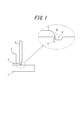
そのため、図1に示す母材1にリブ(rib)2を直立させた面外ガセット継手(out-of-plane gusset welded joint)に対してハンマーピーニング処理を施した場合、ピーニング装置の打撃端子5の先端により溶接止端4に応力集中箇所となる深い溝(打撃痕)6が形成され、溶接ビード3の先端部から疲労き裂(fatigue crack)7が発生する場合があった。
他方、非特許文献1には、ハンマーピーニング(hammer peening)およびTIG処理(tungsten inert gas dressing)による高強度鋼(High Tensile Strength Steel)(SM570)の溶接継手部の疲労強度向上に関し、ハンマーピーニングを施した場合に、上述したような疲労き裂が発生して溶接部の疲労強度が低下する問題に対し、溶接止端の応力集中や残留応力を低減させるための新たなハンマーピーニング法について検討した結果が記載されている。
すなわち、ハンマーピーニングを施す前に、グラインダ(grinder)で溶接止端の一部を予め研削することおよびハンマーピーニングを3パス程度の複数回行うことが疲労ノッチ(fatigue crack)(疲労き裂とも称す)の発生防止に有効であると記載されている。
IMPROVING FATIGUE STRENGTH OF WELDED JOINTS BY HAMMER PEENING TIG-DRESSING:Kengo ANAMI、Chitoshi MIKI、Hideki TANI、Haruhito YAMAMOTO、Structual Eng./Earthquake Eng.、JSCE、Vol.17、NO.1、57s-68s、2000 April)
図解溶接用語辞典、日刊工業、昭和46年9月20日第4版53頁
溶接構造物を製造する際には、作業環境(work environment)、作業能率(operating efficiency)および溶接継手性能(weld join performance)を考慮した溶接方法が選定され、溶接部の疲労強度向上のため、上掲した特許文献1等に記載の溶接部の疲労強度向上方法が施される。また、疲労特性(fatigue property)に優れた溶接継手の特徴が明確であれば、溶接方法の選定と同様に最適な疲労強度向上方法を選定することが可能となる。
しかしながら、特許文献1記載の超音波によるハンマーピーニング方法は、使用する装置が従来の空気圧で端子を駆動する装置と比較すると、高価でしかも入手が困難であるという問題がある。
また、特許文献2記載のレーザ衝撃ハンマーピーニング方法は、素材の前処理が必要で、かつ装置が高価で大きいため、鋼橋の製造に適用することは難しいという問題がある。
また、特許文献2記載のレーザ衝撃ハンマーピーニング方法は、素材の前処理が必要で、かつ装置が高価で大きいため、鋼橋の製造に適用することは難しいという問題がある。
他方、特許文献3には、耐疲労特性に優れた溶接構造物が記載され、疲労き裂発生の可能性が大きい溶接部(welding part with a large possibility that a fatigue crack will occur )に対して好ましい溶接部が開示されているものの、実構造物(real structure)に適用した場合、当該溶接部を得るための装置は入手困難であり、施工能率の点でも問題が残っている。また、特許文献3記載の打撃処理方法は、先端の曲率半径(curvature radius)が、金属材料の厚さの1/2以下でかつ2~10mmの打撃ピンを用い、打撃ピンが打撃中に溶接金属に触れない範囲で、母材金属材料表面に打撃痕を与えるものであるが、打撃端子先端が半球状のため、打撃回数が数多く必要であり、溶接継手部に対して効率的に圧縮残留応力を導入するのは困難である。
さらに、非特許文献1に記載の技術であっても、予め研削することを要し、またハンマーピーニングを複数回行うことなど、施工能率の点で問題が残っている。
本発明は、上記した現状に鑑み開発されたもので、ハンマーピーニング処理を施して、溶接継手部の疲労強度向上を図るための打撃端子およびそれを用いる方法およびその方法を用いた疲労強度特性に優れる溶接継手を提供することを目的とする。
発明者らは、溶接継手の疲労強度を向上させるために、特に疲労き裂が発生しやすい溶接止端部についてその特性を鋭意検討した。その結果、溶接止端部の応力集中を低減させると同時に溶接による引張残留応力を軽減させる手段、すなわちハンマーピーニング処理による打撃端子の形状を略蒲鉾形状にすることで、空気圧振動方式の簡単な装置であっても止端部形状の改善と溶接部への圧縮残留応力の導入とを同時に実現できることを見出した。
本発明は、上記した知見に基づきなされたものである。
本発明は、上記した知見に基づきなされたものである。
すなわち、本発明の要旨構成は次のとおりである。
1.空気圧を用いて打撃端子を振動させる方式(the system which vibrates a impact tip using air pressure)を用い、溶接止端部に打撃を付加することによって溶接継手部の疲労強度向上を図るハンマーピーニング処理を行うための打撃端子であって、
上記打撃端子の先端部が、該打撃端子の進行方向における長さ:1mm以上10mm以下であって、かつその進行方向に直角な断面での曲率半径が1mm以上10mm以下の円弧状である打撃端子。
1.空気圧を用いて打撃端子を振動させる方式(the system which vibrates a impact tip using air pressure)を用い、溶接止端部に打撃を付加することによって溶接継手部の疲労強度向上を図るハンマーピーニング処理を行うための打撃端子であって、
上記打撃端子の先端部が、該打撃端子の進行方向における長さ:1mm以上10mm以下であって、かつその進行方向に直角な断面での曲率半径が1mm以上10mm以下の円弧状である打撃端子。
2.前記打撃端子の先端部における直角な断面が、楕円形の長径を軸とした楕円弧状であって、該楕円形の短径が1mm以上である前記1に記載の打撃端子。
3.空気圧振動方式の打撃端子を用い、溶接止端部に打撃を付加することによって溶接継手部の疲労強度向上を図るハンマーピーニング処理方法において、
上記打撃端子として、その先端部が該端子の進行方向に1mm以上10mm以下の長さを持ち、かつその進行方向に対する直角断面での曲率半径が1mm以上10mm以下の円弧状になる端子を用いて打撃を付加し、溶接止端を挟んで母材と溶接金属にわたる領域である溶接止端部に対して打撃痕を形成するハンマーピーニング処理方法。
上記打撃端子として、その先端部が該端子の進行方向に1mm以上10mm以下の長さを持ち、かつその進行方向に対する直角断面での曲率半径が1mm以上10mm以下の円弧状になる端子を用いて打撃を付加し、溶接止端を挟んで母材と溶接金属にわたる領域である溶接止端部に対して打撃痕を形成するハンマーピーニング処理方法。
4.前記打撃端子を用いて打撃を付加するに際し、その打撃角度を母材の表面に対して60°±20°の範囲とする前記3に記載のハンマーピーニング処理方法。
5.前記打撃端子の進行方向に対する直角断面で、該打撃端子の先端部を、楕円形の長径を軸とした楕円弧状とし、該楕円形の短径を1mm以上とした前記3または4に記載のハンマーピーニング処理方法。
6.前記溶接止端部が、溶接止端を挟んで、溶接金属側に2mm以上でかつ母材側に2mm以上の領域にわたる前記3~5のいずれかに記載のハンマーピーニング処理方法。
7.前記3~6のいずれかに記載のハンマーピーニング処理方法によって、溶接止端を挟んで母材と溶接金属にわたる溶接止端部に打撃を付加された溶接継手であって、
上記打撃により形成された打撃痕の曲率半径が2mm以上である溶接継手。
上記打撃により形成された打撃痕の曲率半径が2mm以上である溶接継手。
8.前記溶接止端部が、溶接止端を挟んで、溶接金属側に2mm以上でかつ母材側に2mm以上の領域にわたる前記7に記載の溶接継手。
本発明によれば、フラックスチッパー(flux chipper)のように、従来の空気圧により端子を駆動する装置であっても、溶接止端部に効果的な打撃処理を行うことができる。すなわち、容易に溶接部の疲労強度改善効果が得られ、産業上、極めて有用な技術である。
以下、本発明の実施形態について、図面を参照して具体的に説明する。
なお、以下の説明で用いる図面は、特徴をわかりやすくするために、便宜上、特徴となる部分を模式的に示している。そのために、各構成要素の寸法比率などが実際と異なる場合がある。
なお、以下の説明で用いる図面は、特徴をわかりやすくするために、便宜上、特徴となる部分を模式的に示している。そのために、各構成要素の寸法比率などが実際と異なる場合がある。
本発明は、溶接ビードの溶接止端部に、打撃端子(以下、単に端子ともいう)を押し付けながら、打撃端子を溶接線方向に移動操作する、いわゆるハンマーピーニング処理を施すことによって、溶接継手部の疲労強度を改善する方法を提供するものである。
なお、本発明の説明において、止端または溶接止端は、母材の面と溶接金属の表面との交線を意味する(非特許文献2参照)。
なお、本発明の説明において、止端または溶接止端は、母材の面と溶接金属の表面との交線を意味する(非特許文献2参照)。
本発明で対象とする母材、リブおよび溶接金属(weld metal)は、従来公知の溶接継手に用いられているものであれば、そのいずれもが適用できる。また、一つの部材に他の部材を溶接して取り付けた溶接継手に対して、本発明は幅広く適用することが可能であるが、その使用箇所の構造や負荷状況(load status)などから、疲労き裂が発生し易い溶接部および溶接ビード(weld bead)を有する溶接継手を対象とすれば、本発明の効果が一段と発揮される。なお、上記した溶接部等は、例えば、橋梁においては橋桁(bridge beam)と橋脚(bridge footing)との溶接部、船舶においては縦通肋骨部材(rib plate)と側板(side plate)との溶接部などが挙げられる。
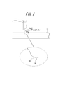
図2は、本発明に係るハンマーピーニング処理方法によって疲労特性が向上する原理を説明するための概略図であり、母材1に、リブ2を廻し溶接(boxing)で溶接した際の溶接継手部を、溶接線方向に対して垂直な断面で示した図である。同図より、溶接ビード3の止端4に対して、所定の角度で端子を押し付けることによって、母材および溶接金属が加圧されて塑性変形(図中、点線で表示)を生じた打撃痕8となっていることが分かる。
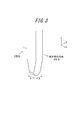
図3は、X方向が打撃の進行方向と直角な方向(溶接線方向に直角な方向)、Y方向が打撃の進行方向(溶接線方向に平行な方向)と定義した場合のX方向、Y方向およびZ方向を説明する図であり、以下に説明するX方向、Y方向およびZ方向はこの定義に従っている。
図4A、図4Bおよび図5に、本発明に従う打撃端子の先端の形状を示す。
本発明における打撃端子は、図4Aおよび図4Bに示すように、打撃端子の先端部が、進行方向(Y方向)に対して直角となる断面(XZ断面)において、a1mmの長さを有する頂部に、曲率半径(r1):1mm以上10mm以下の円弧状の外周部(図4A)を有するものであって、かつ進行方向(Y方向)に1mm以上10mm以下の長さb1mmを有する略蒲鉾形状(図4B)のものである。なお、上記の長さa1は、5~9.5mmの範囲が好適である。さらに好ましくは、5~9mmの範囲である。これは、母材および止端側の広い範囲に打撃することができ、溶接部における止端形状の平滑化に有利だからである。
本発明における打撃端子は、図4Aおよび図4Bに示すように、打撃端子の先端部が、進行方向(Y方向)に対して直角となる断面(XZ断面)において、a1mmの長さを有する頂部に、曲率半径(r1):1mm以上10mm以下の円弧状の外周部(図4A)を有するものであって、かつ進行方向(Y方向)に1mm以上10mm以下の長さb1mmを有する略蒲鉾形状(図4B)のものである。なお、上記の長さa1は、5~9.5mmの範囲が好適である。さらに好ましくは、5~9mmの範囲である。これは、母材および止端側の広い範囲に打撃することができ、溶接部における止端形状の平滑化に有利だからである。
上記の曲率半径(r1)は、1mm未満の場合、止端に応力集中が発生し易い変形が形成される。一方、10mm超の場合、打撃の際の打撃端子と止端部との接触面積が大きくなり過ぎ、止端部に十分な圧縮残留応力を導入することができない。従って、曲率半径(r1)は1mm以上10mm以下とする。
図5Aおよび図5Bは、本発明の他の例に係る打撃端子の形状を示している。同図に示したように、打撃端子の先端部は、進行方向(Y方向)に対して直角となる断面(XZ断面)において、頂部に楕円形の長径(r3)を軸として長さa2mmの楕円弧状の外周部を有し、楕円形の短径(r2)を1mm以上(図5A)とし、図4A、図4Bに示した端子と同じく、進行方向(Y方向)に1mm以上10mm以下の長さb2mmを有する半円柱形状に形成されたものである(図5B)。なお、上記の長さa2は、5~9.5mmの範囲が好適である。さらに好ましくは、5~9mmの範囲である。これは、母材および止端側の広い範囲に打撃することができ、溶接部における止端形状の平滑化に有利だからである。
上記の楕円弧状の外周部を有する打撃端子の場合、楕円形の短径(r2)が1mm未満では、止端部に応力集中部が発生する変形が形成されるため、楕円形の短径(r2)は1mm以上とする。なお、その上限に特段の制限はないが、2mm程度が好ましい。
また、楕円形の長径(r3)は、8mmを越えると溶接止端に打撃することが困難になるため、短径より大きく、6mm程度までが好ましい。
また、楕円形の長径(r3)は、8mmを越えると溶接止端に打撃することが困難になるため、短径より大きく、6mm程度までが好ましい。
図4A、図4B、図5Aおよび図5Bに示した打撃端子は、上述したように、いずれも進行方向(Y方向)に1mm以上10mm以下の長さb1およびb2を有している。そのそれぞれが1mm未満の長さでは、止端に圧縮残留応力を効果的に付与することが出来ないだけでなく、打撃端子にかかる力が大きくなるため先端が潰れやすくなって、頻繁に先端の交換が必要となる。一方、10mm超の長さでは、止端に応力集中部が発生する変形が形成されるだけでなく、止端部に効果的な打撃を付加するために大きな力が必要となるので、大規模な打撃装置になってしまう。従って、b1およびb2はそれぞれ1mm以上、10mm以下の範囲とする。
また、b1およびb2は、a1およびa2と同じかより小さいことが好ましい。これは、打撃端子の接触面積が過度に大きくなると、単位面積あたりにかかる力が弱くなって安定した形状が得られにくいからである。
また、b1およびb2は、a1およびa2と同じかより小さいことが好ましい。これは、打撃端子の接触面積が過度に大きくなると、単位面積あたりにかかる力が弱くなって安定した形状が得られにくいからである。
本発明では、母材の表面に対して60°±20°の角度(以下、打撃角度という)で、溶接止端部に対し打撃を付加することが重要である。
というのは、打撃角度が80°を超えた場合には、溶接金属に対して効果的な打撃を付加することが若干困難となり、一方、打撃角度が40°に満たないと、母材に対して効果的な打撃を付加することができないおそれが招来するからである。
というのは、打撃角度が80°を超えた場合には、溶接金属に対して効果的な打撃を付加することが若干困難となり、一方、打撃角度が40°に満たないと、母材に対して効果的な打撃を付加することができないおそれが招来するからである。
本発明において、打撃角度を調整する方法は、従来公知の方法によることができるが、例えば、打撃開始直前に60度の頂角を持ち、上記Y方向に一定の厚みのある板を母材上に置き、その上にフラックスチッパーを載置して角度を確認してから打撃すれば良い。また、角度を任意に変えられる台に載置したり、透明プラスチック(transparent plastic)製の分度器(protractor)を脇に置いて共同作業者に目視で確認してもらったりしながら、打撃することもできる。
ただし、打撃中の目視による確認は、困難であり、危険も伴うことから、打撃開始時に、打撃端子の先端を打撃位置に接触させた状態で、打撃角度の目視確認をすれば問題はない。
すなわち、打撃角度の確認については一連の作業のうち、初回の打撃の際に範囲内に入っていることを確認できればよい。これは、作業者本人が確認することが困難であることと、全ての作業中に確認することは非効率であるという理由からである。
ただし、打撃中の目視による確認は、困難であり、危険も伴うことから、打撃開始時に、打撃端子の先端を打撃位置に接触させた状態で、打撃角度の目視確認をすれば問題はない。
すなわち、打撃角度の確認については一連の作業のうち、初回の打撃の際に範囲内に入っていることを確認できればよい。これは、作業者本人が確認することが困難であることと、全ての作業中に確認することは非効率であるという理由からである。
また、本発明では、1箇所の溶接部に対して1回の打撃でも、十分に溶接継手の疲労強度を向上させることができるが、止端部内で、打撃する角度を、上記した角度の範囲内で適宜変えることができる。例えば、母材側の打撃の際には、60°より大きな打撃角度で打撃し、ついで止端近傍に対しては打撃角度が60°程度、さらに溶接金属側では、打撃角度が60°より小さな角度で打撃をすることができる。なお、打撃の開始は、母材側からでも溶接金属側からでも行うことができる。また、本発明では、複数回、打撃施工処理をするうちの、少なくとも1回が溶接止端にかかっていればよく、その他の打撃は、母材または溶接金属側のいずれかへの打撃となってしまってもよい。ただし、その結果として、母材、溶接金属の双方に打撃痕が形成されていることが必要である。
本発明において、溶接止端部は、溶接止端を挟んで打撃痕が形成されている母材と溶接金属にわたる領域を意味する。また、その範囲は、溶接止端を基準にして打撃痕の終点(縁)までの長さを測定し、溶接金属側に2mm以上でかつ母材側に2mm以上の領域とすることが好ましい。というのは、それぞれが2mmに満たない場合は、溶接継手部の疲労強度の改善が十分に達成されないおそれがあるからである。
なお、その上限に特段の制限はないが、溶接金属側では、8mm程度であり、一方、母材側では、10mm程度である。
なお、その上限に特段の制限はないが、溶接金属側では、8mm程度であり、一方、母材側では、10mm程度である。
本発明では、上述したようなそれぞれのハンマーピーニング処理条件によって、溶接止端部に打撃を付加して、溶接継手部の疲労強度を改善した溶接継手を形成する。
その際に、上記打撃により形成された打撃痕の曲率半径を、2mm以上とすることが本発明では必須である。
というのは、打撃痕の曲率半径が2mmに満たないと、打撃の付加による応力集中緩和の効果が十分に得られないからである。なお、その上限に特段の制限はないが、溶接部の脚長(leg length)を越えない程度が好ましい。
その際に、上記打撃により形成された打撃痕の曲率半径を、2mm以上とすることが本発明では必須である。
というのは、打撃痕の曲率半径が2mmに満たないと、打撃の付加による応力集中緩和の効果が十分に得られないからである。なお、その上限に特段の制限はないが、溶接部の脚長(leg length)を越えない程度が好ましい。
また、本発明に従う溶接継手は、前述したように、その溶接止端部が、溶接止端を基準にして溶接金属側に2mm以上でかつ母材側に2mm以上の領域にわたっていることが好ましい。
本発明に用いる打撃端子は、前述した形状以外、従来公知の打撃端子を用いることができるが、例えば、工具鋼(tool steel)など、引張強さが1000MPa以上のものを挙げることができる。
本発明に用いる打撃の装置は、従来公知の溶接部の打撃用装置を用いることができるが、フラックスチッパーのように、従来の空気圧で端子を駆動する装置を用いると、設備に要するコストが低減できるために望ましい。
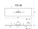
端子の先端部を、XZ断面(端子の進行方向に直角な断面)において、頂部の曲率半径を4.5mmとし、YZ断面(端子の進行方向の断面)の長さを5mmとした打撃端子と、XZ断面(端子の進行方向に直角な断面)において、長径:6mm、短径:3mmとして、長径を軸にした楕円弧状とし、YZ断面(端子の進行方向の断面)の長さを9mmとした打撃端子と、端子の先端部を曲率半径が1.5mmの半球状である打撃端子とをそれぞれ準備した。また、図6Aに示す平行部幅:150mm×長さ:500mm×板厚:12mmの母材1(SM490Y)に、75mm×50mmのリブ2(SM490Y)に廻し溶接3(溶接ワイヤー(weld wire)MXZ200-1.2Φ、シールドガス(shielded gas)100%CO2、溶接電流(weld current)240A-溶接電圧(welding voltage)30V-溶接速度(welding speed)40CPM(cm/min)、溶接入熱10.8KJ/cm)を施した角回し溶接継手(box arc weld joint)を準備した。
ついで、上記溶接継手の止端に、上記打撃端子によるハンマーピーニングを、空気圧(air pressure):約6kg/cm2、周波数(periodicity):90Hzの各条件を固定条件とし、母材に対する打撃の角度を45~70°(度)の範囲内で施した。なお、打撃角度は、打撃開始直前に、透明プラスチック製の分度器を脇に置いて、共同作業者に目視で確認してもらった。
表1に、試験No.と上記の端子形状、打撃角度をそれぞれ示す。
ついで、上記溶接継手の止端に、上記打撃端子によるハンマーピーニングを、空気圧(air pressure):約6kg/cm2、周波数(periodicity):90Hzの各条件を固定条件とし、母材に対する打撃の角度を45~70°(度)の範囲内で施した。なお、打撃角度は、打撃開始直前に、透明プラスチック製の分度器を脇に置いて、共同作業者に目視で確認してもらった。
表1に、試験No.と上記の端子形状、打撃角度をそれぞれ示す。
ハンマーピーニング処理した後の溶接継手の止端半径を、シリコンゴムキャスティング(silicon rubber casting)により実測した。
また、破断回数(応力範囲:200MPa)は、図6Aに示した試験体を用いて、疲労試験機に母材1の両端をチャッキング(chucking)し、リブ2の長手方向に繰返し応力(応力比(stress ratio):0.1,周波数:5~10Hz)を与えることにより求めた。なお、本発明では、破断回数が応力範囲:200MPaにおいて106回を超えていることが良好であるとした。
さらに、上記打撃端子による打撃痕の領域(溶接止端部)の大きさを測定した。具体的には、デジタルノギス(digital caliper square)を用い、リブ端を基準として、打撃前に予めリブ端-溶接止端の距離を測定しておき、打撃後に再びリブ端を基準として、打撃痕の縁までの距離を、溶接金属側、母材側でそれぞれ測定した。その後、溶接止端から打撃痕の縁までの距離を溶接金属側、母材側で差分をとることによりそれぞれ求めた。
打撃痕の曲率半径(止端半径)、破断回数(応力範囲:200MPa)および溶接止端部の範囲の測定結果を、表1にそれぞれ併記する。
また、破断回数(応力範囲:200MPa)は、図6Aに示した試験体を用いて、疲労試験機に母材1の両端をチャッキング(chucking)し、リブ2の長手方向に繰返し応力(応力比(stress ratio):0.1,周波数:5~10Hz)を与えることにより求めた。なお、本発明では、破断回数が応力範囲:200MPaにおいて106回を超えていることが良好であるとした。
さらに、上記打撃端子による打撃痕の領域(溶接止端部)の大きさを測定した。具体的には、デジタルノギス(digital caliper square)を用い、リブ端を基準として、打撃前に予めリブ端-溶接止端の距離を測定しておき、打撃後に再びリブ端を基準として、打撃痕の縁までの距離を、溶接金属側、母材側でそれぞれ測定した。その後、溶接止端から打撃痕の縁までの距離を溶接金属側、母材側で差分をとることによりそれぞれ求めた。
打撃痕の曲率半径(止端半径)、破断回数(応力範囲:200MPa)および溶接止端部の範囲の測定結果を、表1にそれぞれ併記する。

表1より、本発明の端子形状を用いて、母材の表面に対する角度を60°±20°とした場合は、いずれも打撃痕の曲率半径が2mm以上となった。また、破断試験においては、溶接部が破断する前に、試験体(母材)のチャッキング部が破断してしまったが、溶接部の破断までの回数はいずれも、応力範囲:200MPaにおいて、少なくとも106回を超えていることが分かる。一方、処理なしは、応力が引張応力となっており、曲率半径:1.5mmの半球状の端子を用いた場合は、処理なしに比べれば打撃痕の曲率半径が大きくなっているものの、溶接部の破断回数に劣っていることが認められた。打撃端子の先端が半球形状のものでは、先端の強度が十分ではなく、打撃時に母材に圧縮の残留応力を十分導入することができない。また、打撃後に1.5mmの半球状の端子の先端は潰れていた。
また、本発明と溶接ままの止端形状のプロファイル(profile)を図7に示す。同図より、本発明に従う溶接止端部は、溶接ままに比べると止端部の形状がなめらかになっていることが分かる。従って、本発明は、形状改善効果によって、上記した応力集中の緩和効果が発現していることが分かる。
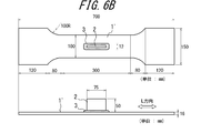
続いて、図6Bに示すように、母材1の代わりに母材1´を使用し、平行部幅:100~150mm×長さ:700mm×板厚:16mmの母材1´(SM490Y)に、75mm×50mmのリブ2(SM490Y)に廻し溶接3(溶接ワイヤーMXZ200-1.2Φ、シールドガス100%CO2、溶接電流240A-溶接電圧30V-溶接速度40CPM、溶接入熱10.8KJ/cm)を施した角回し継手についても疲労試験を行った。
発明例については、打撃端子の先端半径:4.5mm,3mmおよび1.5mmの3種類、長さ:3mm,5mmおよび9mmの3種類を準備した。一方、比較例として、グラインダ処理を施したもの(比較例Aシリーズ)と溶接後の処理を行わなかったもの(溶接まま、比較例Bシリーズ)の疲労試験を行った。
試験結果を表2に示す。
発明例については、打撃端子の先端半径:4.5mm,3mmおよび1.5mmの3種類、長さ:3mm,5mmおよび9mmの3種類を準備した。一方、比較例として、グラインダ処理を施したもの(比較例Aシリーズ)と溶接後の処理を行わなかったもの(溶接まま、比較例Bシリーズ)の疲労試験を行った。
試験結果を表2に示す。
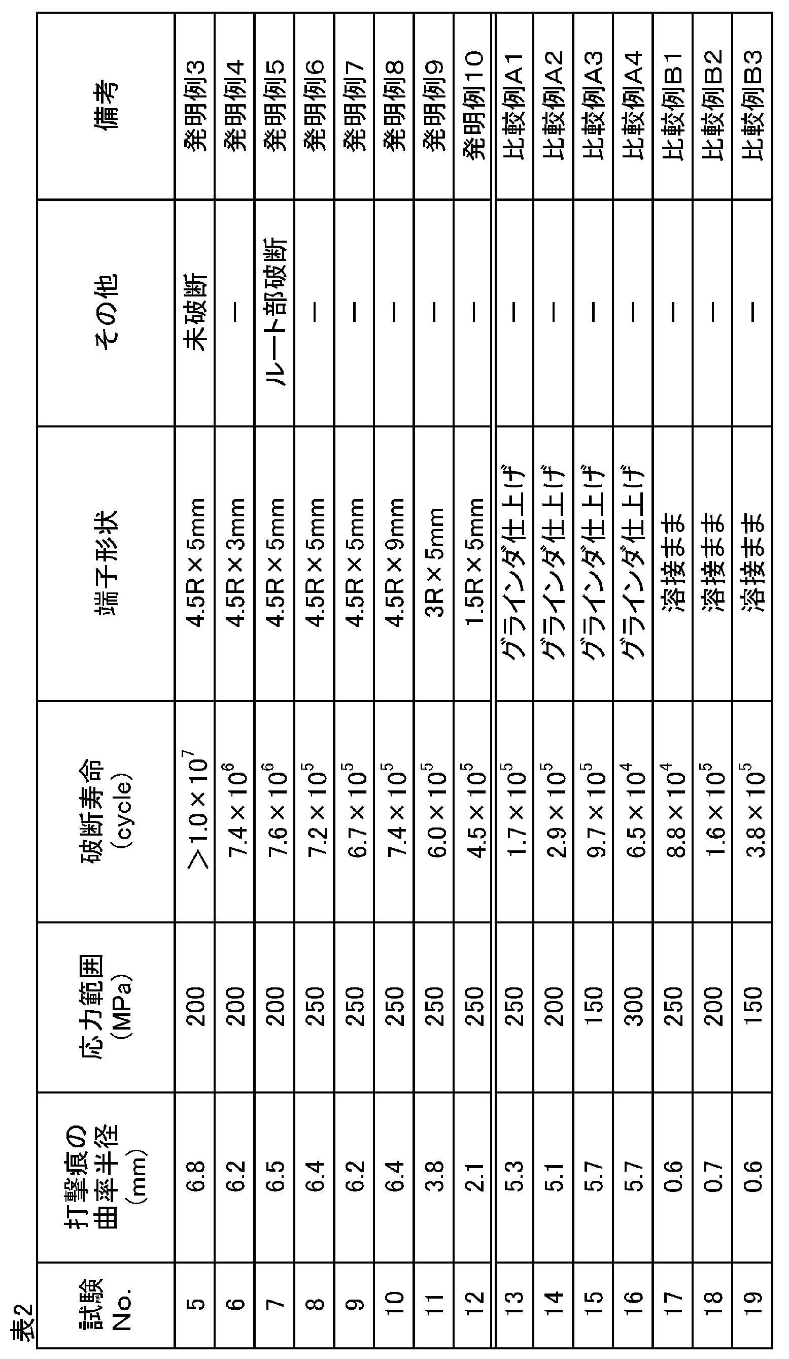
本破断に至るまでの応力載荷回数と、応力範囲との関係を図8に示す。同図および表2より、応力範囲が250MPa以下で、本発明に従う場合、JSSC(日本鋼構造協会)の設計曲線のC等級を十分に満足していることが分かる。特に、打撃端子の先端が曲率半径:1.5mmのものについても十分な疲労寿命が得られており、これは、先端が半球形状のものに比べて、十分な長さを有しているため、先端の強度が高く、止端部に十分な圧縮残留応力を導入できるからである。一方、比較例AシリーズではD等級程度、また比較例BシリーズではE等級程度となっていた。従って、本発明に従うことにより、溶接ままの継手よりも2等級以上向上し、さらに従来のグラインダ処理よりも1等級以上向上していることが分かる。
1,1´ 母材
2 リブ
3 溶接金属(ビード)
4 止端
5 打撃端子(チッパー)
6 溝
7 疲労き裂
8 打撃痕
2 リブ
3 溶接金属(ビード)
4 止端
5 打撃端子(チッパー)
6 溝
7 疲労き裂
8 打撃痕
Claims (8)
- 空気圧を用いて打撃端子を振動させる方式(the system which vibrates a impact tip using air pressure)を用い、溶接止端部に打撃を付加することによって溶接継手部の疲労強度向上を図るハンマーピーニング処理を行うための打撃端子であって、
上記打撃端子の先端部が、該打撃端子の進行方向における長さ:1mm以上10mm以下であって、かつその進行方向に直角な断面での曲率半径が1mm以上10mm以下の円弧状である打撃端子。 - 前記打撃端子の先端部における直角な断面が、楕円形の長径を軸とした楕円弧状であって、該楕円形の短径が1mm以上である請求項1に記載の打撃端子。
- 空気圧振動方式の打撃端子を用い、溶接止端部に打撃を付加することによって溶接継手部の疲労強度向上を図るハンマーピーニング処理方法において、
上記打撃端子として、その先端部が該端子の進行方向に1mm以上10mm以下の長さを持ち、かつその進行方向に対する直角断面での曲率半径が1mm以上10mm以下の円弧状になる端子を用いて打撃を付加し、溶接止端を挟んで母材と溶接金属にわたる領域である溶接止端部に対して打撃痕を形成するハンマーピーニング処理方法。 - 前記打撃端子を用いて打撃を付加するに際し、その打撃角度を母材の表面に対して60°±20°の範囲とする請求項3に記載のハンマーピーニング処理方法。
- 前記打撃端子の進行方向に対する直角断面で、該打撃端子の先端部を、楕円形の長径を軸とした楕円弧状とし、該楕円形の短径を1mm以上とした請求項3または4に記載のハンマーピーニング処理方法。
- 前記溶接止端部が、溶接止端を挟んで、溶接金属側に2mm以上でかつ母材側に2mm以上の領域にわたる請求項3~5のいずれかに記載のハンマーピーニング処理方法。
- 前記請求項3~6のいずれかに記載のハンマーピーニング処理方法によって、溶接止端を挟んで母材と溶接金属にわたる溶接止端部に打撃を付加された溶接継手であって、
上記打撃により形成された打撃痕の曲率半径が2mm以上である溶接継手。 - 前記溶接止端部が、溶接止端を挟んで、溶接金属側に2mm以上でかつ母材側に2mm以上の領域にわたる請求項7に記載の溶接継手。
Priority Applications (3)
| Application Number | Priority Date | Filing Date | Title |
|---|---|---|---|
| PH1/2013/502070A PH12013502070A1 (en) | 2011-04-14 | 2012-04-13 | Impact tip, method for hammer peening , and weld joint using the same |
| KR1020137029931A KR101799376B1 (ko) | 2011-04-14 | 2012-04-13 | 타격 단자 및 해머 피닝 처리 방법 그리고 그것을 이용한 용접 조인트의 제조 방법 |
| CN201280029299.2A CN103596722B (zh) | 2011-04-14 | 2012-04-13 | 击打端头、锤击方法以及利用该方法的焊接接头 |
Applications Claiming Priority (4)
| Application Number | Priority Date | Filing Date | Title |
|---|---|---|---|
| JP2011-090185 | 2011-04-14 | ||
| JP2011090185 | 2011-04-14 | ||
| JP2012091904A JP5919986B2 (ja) | 2011-04-14 | 2012-04-13 | ハンマーピーニング処理方法およびそれを用いた溶接継手の製造方法 |
| JP2012-091904 | 2012-04-13 |
Publications (1)
| Publication Number | Publication Date |
|---|---|
| WO2012140920A1 true WO2012140920A1 (ja) | 2012-10-18 |
Family
ID=47009109
Family Applications (1)
| Application Number | Title | Priority Date | Filing Date |
|---|---|---|---|
| PCT/JP2012/002605 Ceased WO2012140920A1 (ja) | 2011-04-14 | 2012-04-13 | 打撃端子およびハンマーピーニング処理方法並びにそれを用いた溶接継手 |
Country Status (5)
| Country | Link |
|---|---|
| JP (1) | JP5919986B2 (ja) |
| KR (1) | KR101799376B1 (ja) |
| CN (1) | CN103596722B (ja) |
| PH (1) | PH12013502070A1 (ja) |
| WO (1) | WO2012140920A1 (ja) |
Cited By (3)
| Publication number | Priority date | Publication date | Assignee | Title |
|---|---|---|---|---|
| JP5252112B1 (ja) * | 2012-11-13 | 2013-07-31 | Jfeエンジニアリング株式会社 | ピーニング施工方法 |
| EP3689531A4 (en) * | 2017-09-27 | 2020-11-18 | JFE Steel Corporation | BLASTING TREATMENT PROCESS FOR FLAP WELD JOINT, AND WELDED STRUCTURE |
| CN113543927A (zh) * | 2019-03-08 | 2021-10-22 | 杰富意钢铁株式会社 | 针形件锤击方法 |
Families Citing this family (1)
| Publication number | Priority date | Publication date | Assignee | Title |
|---|---|---|---|---|
| CN117265242B (zh) * | 2023-10-11 | 2026-03-10 | 湖北鸿路钢结构有限公司 | 一种钢结构焊接残余应力消除方法 |
Citations (3)
| Publication number | Priority date | Publication date | Assignee | Title |
|---|---|---|---|---|
| JPH0421717A (ja) * | 1990-05-14 | 1992-01-24 | Kawasaki Steel Corp | 溶接継手の疲労強度向上法 |
| JP2006082127A (ja) * | 2004-09-17 | 2006-03-30 | Nippon Steel Corp | 液相拡散接合部品の疲労特性向上方法および液相拡散接合部品 |
| JP2008110374A (ja) * | 2006-10-30 | 2008-05-15 | Nippon Steel Corp | 摩擦攪拌接合方法及び装置 |
Family Cites Families (7)
| Publication number | Priority date | Publication date | Assignee | Title |
|---|---|---|---|---|
| CN1102478C (zh) * | 2000-10-27 | 2003-03-05 | 重庆大学 | 黑色金属件的裂纹焊补方法 |
| JP3899007B2 (ja) * | 2002-10-08 | 2007-03-28 | 新日本製鐵株式会社 | 重ね隅肉溶接継手の疲労強度向上方法 |
| JP2006320960A (ja) * | 2005-04-20 | 2006-11-30 | Nippon Steel Corp | 疲労き裂発生・進展抑止特性に優れた金属部品または金属製構造物およびそれらの製造方法 |
| NO324010B1 (no) * | 2005-04-19 | 2007-07-30 | Aibel As | Fremgangsmåte for å oppnå forhøyet utmattingsstyrke i sveisede metallforbindelser og hammerhode til bruk ved kaldbearbeidelse |
| JP5364981B2 (ja) * | 2007-05-25 | 2013-12-11 | 新日鐵住金株式会社 | 疲労耐久性に優れた船舶および船舶の疲労耐久性向上方法 |
| JP4987816B2 (ja) * | 2008-07-28 | 2012-07-25 | 新日本製鐵株式会社 | 溶接継手の疲労特性を改善する自動打撃処理方法及び自動打撃処理装置 |
| JP5844551B2 (ja) * | 2010-05-31 | 2016-01-20 | Jfeスチール株式会社 | 溶接継手の製造方法 |
-
2012
- 2012-04-13 CN CN201280029299.2A patent/CN103596722B/zh active Active
- 2012-04-13 PH PH1/2013/502070A patent/PH12013502070A1/en unknown
- 2012-04-13 JP JP2012091904A patent/JP5919986B2/ja active Active
- 2012-04-13 KR KR1020137029931A patent/KR101799376B1/ko active Active
- 2012-04-13 WO PCT/JP2012/002605 patent/WO2012140920A1/ja not_active Ceased
Patent Citations (3)
| Publication number | Priority date | Publication date | Assignee | Title |
|---|---|---|---|---|
| JPH0421717A (ja) * | 1990-05-14 | 1992-01-24 | Kawasaki Steel Corp | 溶接継手の疲労強度向上法 |
| JP2006082127A (ja) * | 2004-09-17 | 2006-03-30 | Nippon Steel Corp | 液相拡散接合部品の疲労特性向上方法および液相拡散接合部品 |
| JP2008110374A (ja) * | 2006-10-30 | 2008-05-15 | Nippon Steel Corp | 摩擦攪拌接合方法及び装置 |
Non-Patent Citations (1)
| Title |
|---|
| ISAO MASUKI ET AL.: "Nanko Yosetsu Tsugite no Tsukare Tsuyosa Kaizen ni Oyobosu Yohizumi Oyobi Hammer Peening no Eikyo", JOURNAL OF THE JAPAN WELDING SOCIETY, vol. 51, no. 7, 1982, pages 66 - 72 * |
Cited By (5)
| Publication number | Priority date | Publication date | Assignee | Title |
|---|---|---|---|---|
| JP5252112B1 (ja) * | 2012-11-13 | 2013-07-31 | Jfeエンジニアリング株式会社 | ピーニング施工方法 |
| EP3689531A4 (en) * | 2017-09-27 | 2020-11-18 | JFE Steel Corporation | BLASTING TREATMENT PROCESS FOR FLAP WELD JOINT, AND WELDED STRUCTURE |
| US11633811B2 (en) | 2017-09-27 | 2023-04-25 | Jfe Steel Corporation | Method of peening lap fillet welded joint and welded structures |
| CN113543927A (zh) * | 2019-03-08 | 2021-10-22 | 杰富意钢铁株式会社 | 针形件锤击方法 |
| US12305246B2 (en) | 2019-03-08 | 2025-05-20 | Jfe Steel Corporation | Needle-peening method |
Also Published As
| Publication number | Publication date |
|---|---|
| PH12013502070A1 (en) | 2014-01-06 |
| JP2012228732A (ja) | 2012-11-22 |
| CN103596722B (zh) | 2016-10-05 |
| KR101799376B1 (ko) | 2017-11-20 |
| KR20130137047A (ko) | 2013-12-13 |
| CN103596722A (zh) | 2014-02-19 |
| JP5919986B2 (ja) | 2016-05-18 |
Similar Documents
| Publication | Publication Date | Title |
|---|---|---|
| JP4895407B2 (ja) | ピーニング施工方法とそれを用いた溶接継手 | |
| KR102243326B1 (ko) | 중첩 필렛 용접 조인트의 피닝 처리 방법 및 용접 구조물 | |
| CN103958116B (zh) | 焊接结构物的疲劳损伤抑制方法、打击痕形成用工具、以及焊接结构物 | |
| JP2011131260A (ja) | 溶接部の疲労強度向上方法および溶接継手 | |
| JP5898498B2 (ja) | 溶接部の疲労強度向上方法および溶接継手 | |
| JP5919986B2 (ja) | ハンマーピーニング処理方法およびそれを用いた溶接継手の製造方法 | |
| JP6756241B2 (ja) | 超音波衝撃処理方法 | |
| JP5844551B2 (ja) | 溶接継手の製造方法 | |
| JP6495569B2 (ja) | 打撃痕形成用工具 | |
| JP2006175512A (ja) | 溶接部の疲労強度向上方法およびそれを用いた溶接構造物 | |
| JP5977077B2 (ja) | 溶接部のピーニング方法 | |
| JP2013233590A (ja) | 疲労特性に優れる溶接継手 | |
| JP4837428B2 (ja) | 溶接止端部の超音波衝撃処理方法 | |
| JP2007283369A (ja) | 隅肉溶接部の疲労性能向上方法 | |
| JP2020142291A (ja) | ニードルピーニング方法 | |
| JP6314670B2 (ja) | 疲労特性に優れた構造物 | |
| JP6747416B2 (ja) | 打撃痕形成用工具および溶接継手の作製方法 | |
| JP6349785B2 (ja) | 超音波衝撃処理方法 | |
| JP5599652B2 (ja) | 溶接継手 | |
| WO2012164774A1 (ja) | 溶接継手 | |
| JP6339760B2 (ja) | 溶接構造物の疲労損傷抑制方法および打撃痕形成用工具 | |
| JP2019155470A (ja) | 重ね隅肉溶接継手のピーニング処理方法および溶接構造物 | |
| JP6051817B2 (ja) | 溶接構造物の疲労損傷抑制方法、その方法に用いられる打撃痕形成用工具、および溶接構造物 | |
| JP5252112B1 (ja) | ピーニング施工方法 | |
| JP2013136092A (ja) | 溶接構造物の疲労損傷抑制方法 |
Legal Events
| Date | Code | Title | Description |
|---|---|---|---|
| 121 | Ep: the epo has been informed by wipo that ep was designated in this application |
Ref document number: 12771545 Country of ref document: EP Kind code of ref document: A1 |
|
| NENP | Non-entry into the national phase |
Ref country code: DE |
|
| ENP | Entry into the national phase |
Ref document number: 20137029931 Country of ref document: KR Kind code of ref document: A |
|
| 122 | Ep: pct application non-entry in european phase |
Ref document number: 12771545 Country of ref document: EP Kind code of ref document: A1 |