WO2012140913A1 - 熱転写プリンタ - Google Patents
熱転写プリンタ Download PDFInfo
- Publication number
- WO2012140913A1 WO2012140913A1 PCT/JP2012/002594 JP2012002594W WO2012140913A1 WO 2012140913 A1 WO2012140913 A1 WO 2012140913A1 JP 2012002594 W JP2012002594 W JP 2012002594W WO 2012140913 A1 WO2012140913 A1 WO 2012140913A1
- Authority
- WO
- WIPO (PCT)
- Prior art keywords
- airflow
- ribbon
- ribbon cassette
- thermal head
- transfer printer
- Prior art date
- Legal status (The legal status is an assumption and is not a legal conclusion. Google has not performed a legal analysis and makes no representation as to the accuracy of the status listed.)
- Ceased
Links
Images


Classifications
-
- B—PERFORMING OPERATIONS; TRANSPORTING
- B41—PRINTING; LINING MACHINES; TYPEWRITERS; STAMPS
- B41J—TYPEWRITERS; SELECTIVE PRINTING MECHANISMS, i.e. MECHANISMS PRINTING OTHERWISE THAN FROM A FORME; CORRECTION OF TYPOGRAPHICAL ERRORS
- B41J2/00—Typewriters or selective printing mechanisms characterised by the printing or marking process for which they are designed
- B41J2/315—Typewriters or selective printing mechanisms characterised by the printing or marking process for which they are designed characterised by selective application of heat to a heat sensitive printing or impression-transfer material
- B41J2/32—Typewriters or selective printing mechanisms characterised by the printing or marking process for which they are designed characterised by selective application of heat to a heat sensitive printing or impression-transfer material using thermal heads
- B41J2/325—Typewriters or selective printing mechanisms characterised by the printing or marking process for which they are designed characterised by selective application of heat to a heat sensitive printing or impression-transfer material using thermal heads by selective transfer of ink from ink carrier, e.g. from ink ribbon or sheet
-
- B—PERFORMING OPERATIONS; TRANSPORTING
- B41—PRINTING; LINING MACHINES; TYPEWRITERS; STAMPS
- B41J—TYPEWRITERS; SELECTIVE PRINTING MECHANISMS, i.e. MECHANISMS PRINTING OTHERWISE THAN FROM A FORME; CORRECTION OF TYPOGRAPHICAL ERRORS
- B41J17/00—Mechanisms for manipulating page-width impression-transfer material, e.g. carbon paper
- B41J17/32—Detachable carriers or holders for impression-transfer material mechanism
-
- B—PERFORMING OPERATIONS; TRANSPORTING
- B41—PRINTING; LINING MACHINES; TYPEWRITERS; STAMPS
- B41J—TYPEWRITERS; SELECTIVE PRINTING MECHANISMS, i.e. MECHANISMS PRINTING OTHERWISE THAN FROM A FORME; CORRECTION OF TYPOGRAPHICAL ERRORS
- B41J29/00—Details of, or accessories for, typewriters or selective printing mechanisms not otherwise provided for
- B41J29/377—Cooling or ventilating arrangements
Definitions
- the present invention relates to a thermal transfer printer that performs printing on a sheet by thermal transfer of an ink ribbon and a ribbon cassette used for the printer.
- a color printer described in Patent Document 1 is known.
- a plurality of end face type thermal heads are arranged in series along a conveyance path for conveying a sheet linearly, and a platen is arranged so as to face each thermal head across the sheet.
- Color ink ribbons (yellow, magenta, cyan, and black ink ribbons) are supplied between each thermal head and plantain.
- the present invention has been made in view of such circumstances, and provides a thermal transfer printer that can suppress a temperature rise in a ribbon cassette that accommodates an ink ribbon as much as possible.
- a thermal transfer printer includes a ribbon cassette containing an ink ribbon and a thermal head, and the ribbon cassette is detachably provided so that the ink ribbon is disposed between the thermal head and a sheet.
- a thermal transfer printer that performs printing by thermal transfer of the ink ribbon to the paper by a thermal head, and includes an airflow generation mechanism that generates an airflow, and a control unit that controls the generation of the airflow by the airflow generation mechanism,
- the ribocassette is formed with an airflow passage in which at least a part of the thermal head is arranged, and the airflow generation mechanism is arranged so that the generated airflow passes through the airflow passage of the ribbon cassette.
- the air flow generated by the air flow generation mechanism under the control of the control means passes through the air flow passage of the ribbon cassette, so that the air flow through which at least a part of the thermal head in the air flow passage flows. As a result, the thermal head is cooled more efficiently.
- the thermal transfer printer includes a plurality of ribbon cassettes containing different color ink ribbons, and a thermal head provided corresponding to each of the plurality of ribbon cassettes.
- Each of the plurality of ribbon cassettes is detachably provided so that an ink ribbon is disposed between the ink ribbon and a thermal transfer printer that performs color printing by thermal transfer of each ink ribbon to the paper by a thermal head,
- An airflow generating mechanism for generating an airflow provided independently for the ribbon cassette, and a control means for controlling the generation of airflow by the airflow generating device provided corresponding to each ribbon cassette
- the ribbon cassette is formed with an air flow passage in which at least a part of the thermal head is arranged, and the air flow generation Structure is a structure in which the air flow generated is arranged to pass through the air flow passage of the corresponding ribbon cassette.
- the air flow generated by the air flow generating mechanism under the control of the control means passes through the air flow passage. At least a portion of the thermal head that prints the corresponding color in the passage is exposed to the flowing air current so that the thermal head is more efficiently cooled.
- the air flow passage is formed between the two openings of the ribbon cassette, and one of the two openings of the ribbon cassette is formed.
- the airflow generated by the airflow generation mechanism can be introduced from the opening.
- a duct continuing from the outside of the thermal transfer printer may be coupled to the opening of the ribbon cassette into which the airflow is introduced.
- a first sealing member that seals a portion that introduces an airflow generated by the airflow generation mechanism into one opening of the ribbon cassette, and a joint between the opening of the ribbon cassette and the duct It can be set as the structure which has the 2nd sealing member provided in the part.
- the thermal transfer printer according to the present invention may include a heat sink provided so as to be in contact with the thermal head, and at least a part of the heat sink may be disposed in the airflow passage.
- the airflow generation mechanism may include a fan, and the fan sucks air in the airflow passage and generates an airflow in the airflow passage.
- the air flow generation mechanism may be provided integrally with the ribbon cassette, or may be separate from the ribbon cassette. In the former case, the ribbon cassette can be replaced without considering the alignment with the airflow generator.
- the control unit may generate an air flow with a first amount by the air flow generating mechanism according to a temperature of the thermal head when printing is performed by the thermal head.
- the air flow generation mechanism When the printing of the thermal head that has been printed with the first control means for controlling is completed, the air flow generation mechanism generates the second amount smaller than the first amount according to the temperature of the thermal head.
- a second control means for controlling *
- the airflow is controlled according to the temperature of the thermal head in the same way during printing and after printing, but the second amount, which is smaller than the first amount during printing, particularly after printing is finished. Therefore, the thermal head that has stopped generating heat is cooled by a relatively small amount of airflow. Accordingly, the thermal head can be effectively cooled after the printing is completed while reducing the operation sound of the airflow generation mechanism. In addition, since the state in which the heating element of the thermal head is constantly heated is avoided, the life of the thermal head can be extended.
- the thermal transfer printer of the present invention at least a part of the thermal head in the airflow passage formed in the ribbon cassette is exposed to the airflow flowing through the airflow passage so that the thermal head is cooled more efficiently. Therefore, the temperature rise in the ribbon cassette can be suppressed as much as possible.
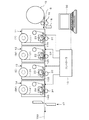
- FIG. 1 is a diagram illustrating an overall structure of a thermal transfer printer according to an embodiment of the present invention. It is a perspective view which shows the structure of the ribbon cassette of the thermal transfer linter shown in FIG. It is sectional drawing which shows the structure of the ribbon cassette of the thermal transfer printer shown in FIG. It is a flowchart which shows the control procedure of the fan with which each ribbon cassette was provided.
- a thermal transfer printer according to an embodiment of the present invention is configured as shown in FIG. *
- a sheet S having a predetermined width wound around a roll 15 is fed by a feeding roller 16, and the sheet S moves on a conveyance path 100.
- This thermal transfer printer includes a Y ribbon cassette 11 containing a yellow (Y) ink ribbon 111, an M ribbon cassette 12 containing a magenta (M) ink ribbon 121, and a C ribbon containing a cyan (C) ink ribbon 131.
- Each ribbon cassette 11, 12, 13, 14 is provided with fan units 115, 125, 135, 145 (airflow generation mechanism) as will be described later.
- the thermal head 21 and the platen roller 31, the thermal head 22 and the platen roller 32, and the thermal head 23 and the platen roller 33 are sequentially spaced from the upstream side in the moving direction of the sheet S.
- the thermal head 24 and the planten roller 34 are arranged so as to sandwich the paper S moving on the transport path 100, respectively.
- the Y ribbon cassette 11 is disposed between the thermal head 21 and the platen roller 31 on the most upstream side in the moving direction of the sheet S, and the yellow (Y) ink ribbon 111 is disposed between the thermal head 21 and the sheet S. It is set so as to be detachable.
- the BK ribbon cassette 14 is disposed between the thermal head 24 and the platen roller 34 on the most downstream side in the moving direction of the paper S, and the black (BK) ink ribbon 141 is disposed between the thermal head 24 and the paper S. It is set so as to be detachable.
- the M ribbon cassette 11 Adjacent to the downstream side of the Y ribbon cassette 11, the M ribbon cassette 11 has a magenta (M) ink ribbon 121 between the thermal head 22 and the sheet S with respect to the set of the thermal head 22 and the platen roller 32. Is detachably set so as to be arranged. Further, adjacent to the upstream side of the BK ribbon cassette 14, the C ribbon cassette 11 has a cyan (C) ink between the thermal head 23 and the sheet S with respect to the set of the thermal head 23 and the platen roller 33. The ribbon 131 is detachably set so as to be disposed. *
- a paper position sensor 18 for detecting the leading edge of the paper S fed from the roll 15 is provided at a predetermined position upstream from the position where the most upstream Y ribbon cassette 11 is set.
- a cutter 17 for cutting the paper S is installed at a predetermined position downstream of the position where the most downstream BK ribbon cassette 14 is set.
- this thermal transfer printer controls the printing operation of each color (Y, M, C, BK) and the operation of the fan units 115, 125, 135, 145 provided in the ribbon cassettes 11, 12, 13, 14.
- a controller 10 is included.
- the controller 10 detects a detection signal from the paper position sensor 18, specifies a print mode (monochrome mode, full color mode, two-color mode, single-color mode) from the host device 50 such as a personal computer, and prints print data, format data, and the like.
- Drive control of the thermal heads 21, 22, 23, and 24 that perform thermal transfer of the ink ribbons 111, 121, 131, and 141 of the respective colors to the paper S based on the data necessary for the printing and the paper S Control related to the printing operation such as feed control is performed.
- the ink ribbon 111 is wound between the ribbon supply roller 112a and the ribbon take-up roller 112b, and the ribbon supply roller.
- the ink ribbon 111 sent out from 112a is taken up by the ribbon take-up roller 112a via a plurality of tension rollers.
- the Y ribbon cassette 11 in which the ink ribbon 111 is stored is set so that the ink ribbon 111 is disposed between the thermal head 21 and the platen roller 31 as described above. In this state, the sheet S passes between the ink ribbon 111 and the plantain roller 31.
- An opening 110a and an opening 110b are formed in two opposing side walls along the conveyance direction of the sheet S in the cassette housing 110, and an airflow passage 113 is formed between the two openings 110a and 110b in the cassette housing 110.
- the bottom of the airflow passage 113 is open, and the entire thermal head 21 is disposed in the airflow passage 116 with the Y ribbon cassette 11 set at a predetermined position.
- the thermal head 21 is provided with a heat sink 211 so as to be in contact with the upper surface thereof, and the entire heat sink 211 is also disposed in the air flow path 113 together with the thermal head 21.
- a fan unit 115 is attached to the cassette housing 110 via a cylindrical shielding material (packing) 116 so as to cover one opening 110a.
- a duct 40 is provided in the device casing 200 of the thermal transfer printer along the four ribbon cassettes 11, 12, 13, and 14 set so as to be sequentially arranged.
- the duct 40 is open to the outside of the thermal transfer printer, and a duct opening 41 is formed in the duct 40 so as to face the other opening 110b formed in the cassette housing 110 of the Y ribbon cassette 11.
- a duct opening 42 is formed so as to face the M ribbon cassette 12 adjacent to the Y ribbon cassette 11, and a duct opening (not shown) is formed so as to face each of the other ribbon cassettes 13 and 14. ing.
- a shielding material (packing) 117 is sandwiched between the Y ribbon cassette 11 and the duct 40, and the duct 40 and the Y ribbon cassette 11 are inside through the opening 41 and the opening 110b.
- the airflow passage 113 formed in the communication is communicated.
- the other ribbon cassettes 12, 13, and 14 are in the set state, and the duct 40 and the airflow passage are in communication.
- the fan units 115, 125, 135, and 145 attached to the ribbon cassettes 11, 12, 13, 13, and 14 are the device casings of the thermal transfer printer. It faces the ventilation window 201 formed in 200.
- the thermal transfer printer As described above, when the fan unit 115 provided in the Y ribbon cassette 11 is operated, the outside air passing through the duct 40 passes through the duct opening 41 of the duct 40 and the opening 110b of the cassette housing 110 by the suction action. Is introduced into the airflow passage 113, and the outside air is discharged from the other opening 110 a of the cassette housing 110 through the airflow passage 113 to the outside of the thermal transfer printer through the fan unit 115 and the ventilation window 201. Since the thermal head 21 and the heat sink 211 are exposed to the airflow in the airflow passage 113 formed by the flow of outside air introduced in this way, the thermal head 21 is cooled more efficiently than the heat sink 211 is cooled by natural heat dissipation. It becomes like this.
- each ribbon cassette 11 (12, 13, 14) can be set at a predetermined position without considering the alignment.
- each fan unit 115 (125, 135, 145) can also be provided in the apparatus housing 200 of the thermal transfer printer as a separate body from each ribbon cassette 11 (12, 13, 14). In this case, when each ribbon cassette 11 (12, 13, 14) is set at a predetermined position, the fan unit is set so that the positional relationship with the opening 110a of the ribbon cassette 11 (12, 13, 14) is appropriate.
- 115 (125, 135, 145) must be installed in the device casing 200.
- the air flow is generated in the air flow passage 113 by the intake action of the fan unit 115 (125, 135, 145), but the air flow passage 113 generates the air flow in the air flow passage 113 by the fan unit 115 (125, 135, 145). An air flow can also be generated.
- a dustproof filter is provided in the opening portion of the device housing 200 in the thermal transfer printer of the duct 40 and / or each of the duct openings 41 and 42. Thereby, it is possible to prevent dust from the outside from entering the apparatus housing 200 of the thermal transfer printer and the ribbon cassettes 11, 12, 13, and 14. *
- the controller 10 designates a print mode designated together with a print request from the host device 50 (personal computer), for example, a monochrome mode in which the print color is black (BK), and all four colors (yellow (Y), magenta ( M), cyan (C), black (BK)) full color mode, two-color mode with only two print colors, and single-color mode with a single print color (excluding black).
- the printing operation by the thermal head to be driven is controlled in synchronization with the movement of the paper S sent on the transport path 100 from the initial position.
- the controller 10 controls the fan unit of the ribbon cassette set with respect to the thermal head for printing according to the procedure shown in FIG. *
- printing is performed while the thermal head 21 presses the yellow (Y) ink ribbon 111 of the Y ribbon cassette 11 against the platen roller 31 together with the paper S in accordance with a print job instruction in the single color mode or full color mode from the host device 50.
- the control of the fan unit 115 will be described by taking the case of the case as an example.
- the other fan units 125, 135, and 145 are similarly controlled when printing is performed by the corresponding thermal heads 22, 23, and 24. *
- the controller 10 acquires the temperature T of the thermal head 21 that is printing (S11).
- the heat sink 211 of the thermal head 21 is provided with a temperature detector (not shown) such as a thermistor, and the controller 10 acquires the temperature T detected by this temperature detector as the temperature of the thermal head 21. .
- the controller 10 determines whether or not the acquired temperature T of the thermal head 21 has exceeded the first threshold T1 (S12).
- the controller 10 performs the temperature of the thermal head 21.
- T exceeds the first threshold T1 YES in S12
- the fan unit 115 is turned on (S13). *
- the controller 10 controls the drive of the fan unit 115 so that a predetermined air volume (normal air volume: a first air stream) is generated.
- the fan motor of the fan unit 115 may be controlled at a constant rotational speed, or the PWM drive signal for the fan motor may be duty controlled according to the detected temperature T. Due to the operation of the fan unit 115 in accordance with the drive control, as described above, the normal air volume airflow generated by the outside air introduced from the duct 40 is generated in the airflow passage 113 of the Y ribbon cassette 11 and is exposed to the airflow. The head 21 and the heat sink 211 are cooled.
- the controller 10 controls the fan unit 115 in this manner, acquires the temperature T of the thermal head 21 (S14), determines whether printing (one print job) by the thermal head 21 is completed (S15), And the determination (S16) of whether or not the temperature T of the acquired thermal head 21 is below the second threshold value T2 smaller than the first threshold value T1 is repeatedly executed.
- the controller 10 turns off the fan unit 115 (S17), and again the temperature of the thermal head 21 during printing. Whether T exceeds a relatively high first threshold value T1 is monitored (S11, S12). Thereafter, the same control (S11 to S17) as described above is performed. As a result, when the temperature T of the thermal head 21 exceeds the first threshold T1 (YES in S1), the fan unit 115 is turned on (S13), and the drive control of the fan unit 115 is performed so that the normal air volume is generated. When the temperature T of the thermal head 21 falls below the second threshold T2, the fan unit 21 is turned off (S17). *
- the controller 10 controls to drive the fan unit 115 so that a weak air volume is generated (S18), and confirms whether or not printing is resumed (start of the next print job) (YES in S15, S19). Then, it is monitored whether or not the temperature T of the thermal head 21 has fallen below the second threshold value T2 (S14, S15, S16). In the process, when the temperature T of the fan unit 115 falls below the second threshold value T2 (YES in S16), the controller 10 turns off the fan unit 115 controlled by the weak air volume (S17). Thereafter, assuming that printing by the thermal head 21 is not performed, the controller 10 removes the fan unit 115 based on the temperature of the thermal head 21 from the control target.
- the controller 10 controls the drive of the fan unit 115 with the normal air volume (S20). ). Then, the controller 10 continues the monitoring operation of whether or not the print job is finished (S15) and whether or not the temperature T of the thermal head 21 is lower than the second threshold T2 (S14, 16, and S17).
- the airflow is controlled in accordance with the temperature of the thermal head 21 in the same way during printing and after printing, but particularly during printing after printing is completed. Therefore, the thermal head 21 that has stopped generating heat after the completion of a series of print jobs is cooled by a relatively small amount of air flow. Accordingly, the thermal head 21 can be effectively cooled while reducing the operation sound of the fan unit 115 after the printing is completed.
- the rotational speed (air volume) of the fan motor can be controlled according to the printing rate calculated from the print data.
- the thermal transfer printer described above can be configured without providing the duct 40.
- the fan unit 115 125, 135, 1405
- the air in the device casing 200 of the thermal transfer printer is introduced into the air flow passage 113 of each ribbon cassette 11 (12, 13, 14), and the air flow passage.
- the air flowing through 113 is discharged from the ventilation window 201 to the outside.
- each ribbon cassette may not be the one in which the entire thermal head 21 and heat sink 211 are disposed. It suffices that at least a part of the thermal head 21 and / or the heat sink 211 is disposed in the airflow passage 113.
- the above-described thermal transfer printer is a full-color print provided with four ribbon cassettes 11, 12, 13, and 14 that accommodate ink ribbons 111, 121, 131, and 141 of different colors (BK, C, M, and Y).
- the present invention is not limited to this, and a thermal transfer printer including a single or a plurality of ribbon cassettes other than four may be used.
- the thermal transfer color printer according to the present invention has an effect that the temperature rise in the ribbon cassette that accommodates the ink ribbon can be suppressed as much as possible, and thermal transfer that performs printing on a sheet by thermal transfer of the ink ribbon. Useful as a printer.
Landscapes
- Electronic Switches (AREA)
- Impression-Transfer Materials And Handling Thereof (AREA)
Abstract
【課題】インクリボンを収容するリボンカセット内の温度上昇を極力抑えることのできる熱転写プリンタを提供することである。【解決手段】インクリボン111を収納したリボンカセット11とサーマルヘッド21とを有し、インクリボン111のサーマルヘッド21による用紙Sへの熱転写によってプリントを行う熱転写プリンタであって、気流を発生させる気流発生機構115と、気流発生機構115による気流の発生を制御する制御手段10とを有し、リボカセット11には、サーマルヘッド21の少なくとも一部が配置される気流通路113が形成され、気流発生機構115は、発生する気流がリボンカセット11の気流通路113を通るように配置された構成となる。
Description
本発明は、インクリボンの熱転写によって用紙に対するプリントを行う熱転写プリンタ及びそれに用いられるリボンカセットに関する。
従来、特許文献1に記載のカラープリンタが知られている。このカラープリンタでは、複数の端面型サーマルヘッドが用紙を直線的に搬送する搬送路に沿って直列的に配置され、各サーマルヘッドに対して用紙を挟んで対向するようにプラテンが配置されている。そして、各サーマルヘッドとプランテンとの間に、色インクリボン(イエロー、マゼンタ、シアン、黒の各インクリボン)が供給されるようになっている。
特開平09-094987号公報
ところで、この種の熱転写カラープリンタでは、各プリント色に対応したインクリボンをカセット化して、インクリボンの交換を容易にすることが考えられる。しかしながら、そのカセット化に伴って、サーマルヘッドから発生する熱がカセット内にこもってプリント色に影響を与えるおそれがあり、また、サーマルヘッドの耐熱性を更に向上させなければならずコストアップの要因になる。
本発明は、このような事情に鑑みてなされたもので、インクリボンを収容するリボンカセット内の温度上昇を極力抑えることのできる熱転写プリンタを提供するものである。
本発明に係る熱転写プリンタは、インクリボンを収納したリボンカセットとサーマルヘッドとを有し、該サーマルヘッドと用紙との間に前記インクリボンが配置されるように前記リボンカセットが着脱自在に設けられ、前記インクリボンのサーマルヘッドによる前記用紙への熱転写によってプリントを行う熱転写プリンタであって、気流を発生させる気流発生機構と、該気流発生機構による気流の発生を制御する制御手段とを有し、前記リボカセットには、前記サーマルヘッドの少なくとも一部が配置される気流通路が形成され、前記気流発生機構は、発生する気流が前記リボンカセットの前記気流通路を通るように配置された構成となる。
このような構成により、制御手段の制御のもとに気流発生機構にて発生する気流がリボンカセットの気流通路を通るようになるので、該気流通路にあるサーマルヘッドの少なくとも一部が流れる気流にさらされて当該サーマルヘッドがより効率的に冷却されるようになる。
また、本発明に係る熱転写プリンタは、異なる色のインクリボンを収納した複数のリボンカセットと、該複数のリボンカセットのそれぞれに対応させて設けられたサーマルヘッドとを有し、該サーマルヘッドと用紙との間にインクリボンが配置されるように前記複数のリボンカセットのそれぞれが着脱自在に設けられ、各インクリボンのサーマルヘッドによる前記用紙への熱転写によってカラープリントを行う熱転写プリンタであって、各リボンカセットに対して独立して設けられた気流を発生させる気流発生機構と、各リボンカセットに対応して設けられた前記気流発生機器による気流の発生を制御する制御手段とを有し、前記各リボンカセットには、前記サーマルヘッドの少なくとも一部が配置される気流通路が形成され、前記気流発生機構は、発生する気流が対応するリボンカセットの気流通路を通るように配置された構成となる。
このような構成により、異なる色のインクリボンを収納した複数のリボンカセットのそれぞれにおいて、制御手段の制御のもとに気流発生機構にて発生する気流が気流通路を通るようになるので、該気流通路にある対応する色のプリントを行うサーマルヘッドの少なくとも一部が流れる気流にさらされて当該サーマルヘッドがより効率的に冷却されるようになる。
本発明に係る熱転写プリンタにおいて、前記リボンカセットの筐体に2つの開口が形成され、前記気流通路は前記リボンカセットの2つの開口の間に形成され、前記リボンカセットの2つの開口のうちの一方の開口から前記気流発生機構にて発生する気流が導入される構成とすることができる。
このような構成により、リボンカセットの筐体に形成された2つの開口のうちの一方の開口から気流発生機構にて発生する気流が導入されると、その気流が気流通路を通って他方の開口からリボンカセットの外部に出ていく。
また、本発明に係る熱転写プリンタにおいて、前記気流の導入される前記リボンカセットの開口に当該熱転写プリンタの外部に続くダクトが結合した構成とすることができる。
このような構成により、熱転写プリンタの外部からダクトを通して取り入れられる空気による気流が、リボンカセットの筐体に形成された2つの開口のうちの一方の開口から気流通路に導入されて、該気流通路を通って他方の開口からリボンカセットの外部に出ていく。
本発明に係る熱転写プリンタにおいて、前記リボンカセットの一方の開口に前記気流発生機構にて発生する気流を導入する部分を密閉する第1の密閉部材と、前記リボンカセットの開口と前記ダクトとの接合部に設けられた第2の密閉部材とを有する構成とすることができる。
このような構成により、気流通路以外に漏れる気流を極力少なくすることができる。
更に、本発明に係る熱転写プリンタにおいて、前記サーマルヘッドに接するように設けられたヒートシングを有し、該ヒートシングの少なくとも一部は、前記気流通路内に配置される構成とすることができる。
このような構成により、サーマルヘッドの少なくとも一部とともに該サーマルヘッドに接するヒートシンクの少なくとも一部が気流通路を通る気流にさらされるようになるので、サーマルヘッドを更に良好に冷却することができるようになる。
また、本発明に係る熱転写プリンタにおいて、前記気流発生機構はファンを有し、該ファンが、前記気流通路の空気を吸引して、当該気流通路に気流を発生させる構成とすることができる。
このような構成により、ファンを動作させることにより、気流通路内に気流が発生するので、該急流通路内に少なくとも一部が配置されるサーマルヘッドをより効率的に冷却することができるようになる。
更に、本発明に係る熱転写プリンタにおいて、前記気流発生機構は、前記リボンカセットに一体的に設けられるようにしても、また、前記リボンカセットと別体とすることもできる。前者の場合、リボンカセットの交換を気流発生装置との位置合わせを考慮することなく行うことができる。
また、本発明に係る熱転写プリンタにおいて、前記制御手段は、前記サーマルヘッドによるプリントがなされているときに、該サーマルヘッドの温度に応じて前記気流発生機構による第1の量での気流の発生を制御する第1制御手段と、プリントを行っていた前記サーマルヘッドの当該プリントが終了すると、前記サーマルヘッドの温度に応じて前記気流発生機構による前記第1の量より少ない第2の量での発生を制御する第2制御手段とを有する構成とすることができる。
このような構成により、プリント中とプリント終了後とでは同じようにサーマルヘッドの温度に応じた気流の制御がなされるが、特にプリントが終了後では、プリント中の第1の量より少ない第2の量での気流の発生になるので、発熱を停止したサーマルヘッドが比較的少ない量の気流にて冷却されるようになる。従って、プリント終了後において、気流発生機構の動作音を低減させつつサーマルヘッドを有効に冷却することができるようになる。また、サーマルヘッドの発熱体が常に高温になる状態を回避することになるので、サーマルヘッドの寿命を延ばすことができる。
本発明に係る熱転写プリンタによれば、リボンカセットに形成された気流通路にあるサーマルヘッドの少なくとも一部が該気流通路を流れる気流にさらされて当該サーマルヘッドがより効率的に冷却されるようになるので、リボンカセット内の温度上昇を極力抑えることができるようになる。
以下、本発明の実施の形態について図面を用いて説明する。
本発明の実施の一形態に係る熱転写プリンタは、図1に示すように構成される。
図1において、この熱転写プリンタでは、ロール15に巻かれた所定幅の用紙Sが繰り出しローラ16によって繰り出され、その用紙Sが搬送路100を移動するようになっている。この熱転写プリンタは、イエロー(Y)のインクリボン111を収納したYリボンカセット11、マゼンタ(M)のインクリボン121を収納したMリボンカセット12、シアン(C)のインクリボン131を収納したCリボンカセット13、及び黒(BK)のインクリボン141を収納したBKリボンカセット14の4つのリボンカセットを有している。また、各リボンカセット11、12、13、14には、後述するように、ファンユニット115、125、135、145(気流発生機構)が設けられている。搬送路100に沿って、用紙Sの移動方向における上流側から順次所定の間隔をもって、サーマルヘッド21とプラテンローラ31とが、サーマルヘッド22とプラテンローラ32とが、サーマルヘッド23とプラテンローラ33とが、及びサーマルヘッド24とプランテンローラ34とが、それぞれ搬送路100を移動する用紙Sを挟むように配置されている。
用紙Sの移動方向における最上流側のサーマルヘッド21とプラテンローラ31との組に対して、Yリボンカセット11が、サーマルヘッド21と用紙Sとの間にイエロー(Y)のインクリボン111が配置されるように着脱自在にセットされる。用紙Sの移動方向における最下流側のサーマルヘッド24とプラテンローラ34との組に対して、BKリボンカセット14が、サーマルヘッド24と用紙Sとの間に黒(BK)のインクリボン141が配置されるように着脱自在にセットされる。Yリボンカセット11の下流側に隣接して、サーマルヘッド22とプラテンローラ32との組に対して、Mリボンカセット11が、サーマルヘッド22と用紙Sとの間にマゼンタ(M)のインクリボン121が配置されるように着脱自在にセットされる。また、BKリボンカセット14の上流側に隣接して、サーマルヘッド23とプラテンローラ33との組に対して、Cリボンカセット11が、サーマルヘッド23と用紙Sとの間にシアン(C)のインクリボン131が配置されるように着脱自在にセットされる。
最上流側のYリボンカセット11のセットされる位置より上流側の所定位置にはロール15から繰り出される用紙Sの先端を検出する用紙位置センサ18が設けられている。また、最下流側のBKリボンカセット14のセットされる位置より下流側の所定位置には、用紙Sを切断するカッター17が設置されている。
また、この熱転写プリンタは、各色(Y、M、C、BK)のプリント動作、及び各リボンカセット11、12、13、14に設けられたファンユニット115、125、135、145の動作を制御するコントローラ10を有している。コントローラ10は、用紙位置センサ18からの検出信号、パーソナルコンピュータ等の上位装置50からのプリントモード(モノクロモード、フルカラーモード、2色モード、単色モード)の指定、及びプリントデータ、フォーマットデータ等のプリントに必要なデータに基づいて各色のインクリボン111、121、131、141の用紙Sへの熱転写を行うサーマルヘッド21、22、23、24の駆動制御や用紙S
の送り制御等のプリント動作に係る制御を行う。このプリント動作により、搬送路100を移動する用紙Sの各ラベルに、指定された色(BK、C、M、Yのフルカラー、モノクロ、2色、単色)によるプリントがなされる。そして、そして、プリント済みのラベルがカッター17を通過する毎に、一時的に用紙Sの送り及びプリント動作が止められて、カッター17により用紙Sが切断され、プリント済みのラベルが順次搬送路100から排出される。
の送り制御等のプリント動作に係る制御を行う。このプリント動作により、搬送路100を移動する用紙Sの各ラベルに、指定された色(BK、C、M、Yのフルカラー、モノクロ、2色、単色)によるプリントがなされる。そして、そして、プリント済みのラベルがカッター17を通過する毎に、一時的に用紙Sの送り及びプリント動作が止められて、カッター17により用紙Sが切断され、プリント済みのラベルが順次搬送路100から排出される。
なお、各ファンユニット115、125、135、145の制御の詳細については後述する。
Yリボンカセット11の詳細な構造について、図1とともに図2及び図3を参照して説明する。なお、他のリボンカセット12、13、14についても同様の構造となっているので、その説明は省略する。
図1とともに図2及び図3を参照するに、Yリボンカセット11のカセット筐体110内において、リボン供給ローラ112aとリボン巻取りローラ112bとの間にインクリボン111が巻きかけられ、リボン供給ローラ112aから送り出されたインクリボン111が複数のテンションローラを介してリボン巻取りローラ112aに巻き取られるようになっている。このようにインクリボン111が収納されたYリボンカセット11は、前述したように、サーマルヘッド21とプラテンローラ31との間にインクリボン111が配置されるようにセットされる。この状態で、用紙Sがインクリボン111とプランテンローラ31との間を通過するようになる。
カセット筐体110の用紙Sの搬送方向に沿った2つの対向する側壁に開口110aと開口110bとが形成され、カセット筐体110内のそれら2つの開口110a、110bの間に気流通路113が形成されている。気流通路113は底が開放しており、Yリボンカセット11を所定位置にセットした状態で、サーマルヘッド21全体が気流通路116内に配置される。サーマルヘッド21には、その上面に接するようにヒートシンク211が設けられており、このヒートシンク211全体もサーマルヘッド21とともに気流通路113内に配置される。
カセット筐体110には、一方の開口110aを覆うように筒状の遮蔽材(パッキン)116を介してファンユニット115が取り付けられている。当該熱転写プリンタの機器筐体200内には、順次並べられるようにセットされた4つのリボンカセット11、12、13、14に沿ってダクト40が設けられている。ダクト40は当該熱転写プリンタの外部に開放しており、そのダクト40には、Yリボンカセット11のカセット筐体110に形成された他方の開口110bに対向するようにダクト開口41が形成され、同様に、Yリボンカセット11に隣接するMリボンカセット12に対向するようにダクト開口42が形成されるとともに、他のリボンカセット13、14のそれぞれに対向するようにダクト開口(図示略)が形成されている。そして、Yリボンカセット11がセットされた状態で、Yリボンカセット11とダクト40との間に遮蔽材(パッキン)117が挟まれ、開口41及び開口110bを介してダクト40とYリボンカセット11内に形成された気流通路113とが連通するようになっている。他のリボンカセット12、13、14も同様に、セットされた状態で、ダクト40と気流通路とが連通した状態となる。
各リボンカセット11、12、13、14がセットされた状態で、各リボンカセット11、12、13、13、14に取り付けられたファンユニット115、125、135、145が当該熱転写プリンタの機器筐体200に形成された通気窓201に対向するようになっている。
前述したような熱転写プリンタでは、Yリボンカセット11に設けられたファンユニット115が動作すると、その吸引作用によって、ダクト40を通る外気が当該ダクト40のダクト開口41及びカセット筐体110の開口110bを介して気流通路113に導入され、その外気が気流通路113を通ってカセット筐体110の他方の開口110aから、更にファンユニット115及び通気窓201を通して当該熱転写プリンタの外部に排出される。このように導入された外気の流れにより形成される気流通路113内の気流にサーマルヘッド21及びヒートシンク211がさらされるので、サーマルヘッド21がヒートシンク211の自然放熱よる冷却より更に効率的に冷却されるようになる。その結果、イエロー(Y)のインクリボンを収容するYリボンカセット11(カセット筐体110)内の温度上昇を極力抑えることができる。また、他のリボンカセット12、13、14においても同様に対応するファンユニット125、135、145の動作によって発生する外気の気流によって対応するサーマルヘッド22、23、24がより効率的に冷却されるようになり、各リボンカセット12、13、14(カセット筐体110)内の温度上昇を極力抑えることができる。
また、各リボンカセット11(12、13、14)にファンユニット115(125、135、145)が一体的に設けられているので、開口110aとファンユニット115(125、135、145)との位置合わせを考慮することとなく、各リボンカセット11(12、13、14)を所定位置にセットすることができる。ただし、各ファンユニット115(125、135、145)は、各リボンカセット11(12、13、14)と別体として当該熱転写プリンタの機器筐体200内に設けることもできる。この場合は、各リボンカセット11(12、13、14)を所定位置にセットしたときに、当該リボンカセット11(12、13、14)の開口110aとの位置関係が適正となるようにファンユニット115(125、135、145)を機器筐体200内に設置する必要がある。
更に、ファンユニット115(125、135、145)の吸気作用によって気流通路113に気流を発生させるものであったが、ファンユニット115(125、135、145)の気体の吹き出し作用によって気流通路113に気流を発生させるようにすることもできる。
なお、図示されてはいないが、ダクト40の当該熱転写プリンタにおける機器筐体200の開口部分、及び/または、各ダクト開口41、42には、防塵フィルタが設けられている。これにより、外部からのダストが熱転写プリンタの機器筐体200内や、各リボンカセット11、12、13、14内に進入することを防止することができる。
この熱転写プリンタの動作について更に詳細に説明する。
この熱転写プリンタが起動されると、図1に示すように、ロール15から繰り出される用紙Sが、その先端が用紙位置センサ18にて検出される位置(初期位置)にセットされる。そして、コントローラ10は、上位装置50(パーソナルコンピュータ)からプリント要求とともに指定されるプリントモード、例えば、プリント色が黒(BK)のモノクロモード、プリント色が全4色(イエロー(Y)、マゼンタ(M)、シアン(C)、黒(BK))のフルカラーモード、プリント色が2色だけの2色モード、及びプリント色が単一色(黒を除く)の単色モードのいずれかに応じて決められる駆動すべきサーマルヘッドによるプリント動作を前記初期位置から搬送路100上を送られる用紙Sの移動に同期させて制御する。その過程で、コントローラ10は、プリントを行うサーマルヘッドに対してセットされたリボンカセットのファンユニットを図4に示す手順に従って制御する。
例えば、上位装置50からの単色モードまたはフルカラーモードでのプリントジョブの指示に従ってサーマルヘッド21がYリボンカセット11のイエロー(Y)のインクリボン111を用紙Sとともにプラテンローラ31に押し付けつつプリントがなされている場合を例に、ファンユニット115の制御について説明する。他のファンユニット125、135、145についても、対応するサーマルヘッド22、23、24によるプリントがなされる場合に同様に制御される。
図1において、コントローラ10は、プリント中であるサーマルヘッド21の温度Tを取得する(S11)。例えば、サーマルヘッド21のヒートシンク211にはサーミスタ等の温度検出器(図示略)が設けられており、コントローラ10は、この温度検出器にて検出される温度Tをサーマルヘッド21の温度として取得する。そして、コントローラ10は、取得したサーマルヘッド21の温度Tが第1閾値T1を超えたか否かを判定する(S12)。コントローラ10は、プリント中のサーマルヘッド21の温度Tの取得(S11)及びその温度Tが第1閾値T1を超えたか否かの判定(S12)を繰り返し実行する過程で、そのサーマルヘッド21の温度Tが第1閾値T1を超えると(S12でYES)、ファンユニット115をオンさせる(S13)。
コントローラ10は、所定の風量(通常風量:第1の量の気流)が発生するようにファンユニット115を駆動制御する。この場合、ファンユニット115のファンモータを一定の回転速度で制御するようにしても、ファンモータに対するPWM駆動信号を検出温度Tに応じてデューティ制御するようにしてもよい。その駆動制御に従ったファンユニット115の動作によって、前述したように、ダクト40から導入される外気による通常風量の気流がYリボンカセット11の気流通路113内で発生し、その気流にさらされるサーマルヘッド21及びヒートシング211が冷却される。コントローラ10は、このようにファンユニット115を制御しつつ、サーマルヘッド21の温度Tの取得(S14)、サーマルヘッド21によるプリント(1つのプリントジョブ)が終了したか否かの判定(S15)、及び取得されるサーマルヘッド21の温度Tが前記第1閾値T1より小さい第2閾値T2を下回るか否かの判定(S16)を繰り返し実行する。
その過程で、冷却されるサーマルヘッド21の温度Tが第2閾値を下回ると(S16でYES)、コントローラ10は、ファンユニット115をオフさせ(S17)、再び、プリント中のサーマルヘッド21の温度Tが比較的高い第1閾値T1を超えるか否かを監視する(S11、S12)状態になる。その後、前述したのと同様の制御(S11~S17)がなされる。その結果、サーマルヘッド21の温度Tが第1閾値T1を超えると(S1でYES)、ファンユニット115がオンされて(S13)、通常風量が発生するようにそのファンユニット115の駆動制御がなされ、サーマルヘッド21の温度Tが第2閾値T2を下回るとファンユニット21がオフされる(S17)。
上述した制御の過程で、ファンユニット115がオンして(S13)、通常風量が発生するように制御される状態において、サーマルヘッド21によるプリント(1つのプリントジョブ)が終了すると(S15でYES)、コントローラ10は、前記プリント中の場合より少ない所定の風量(弱風量:第2の量の気流)が発生するようにファンユニット115を駆動制御する(S18)。このときサーマルヘッド21は、上昇してYインクリボン111及び用紙Sのプラテンローラ31への押圧を解除している。そして、前記駆動制御に従ったファンユニット115の動作によって、前述したように、ダクト40から導入される外気による弱風量の気流がYリボンカセット11の気流通路113内で発生し、既に発熱動作(プリント)を終えているサーマルヘッド21がその弱風量の気流にさらされて冷却される。
その後、コントローラ10は、ファンユニット115を弱風量が発生するように駆動制御しつつ(S18)、プリントが再開(次のプリントジョブの開始)されたか否か(S15でYES、S19)の確認、及びサーマルヘッド21の温度Tが第2閾値T2を下回ったか否かを監視する(S14、S15、S16)。その過程で、ファンユニット115の温度Tが第2閾値T2を下回ると(S16でYES)、コントローラ10は、前記弱風量にて
制御されていたファンユニット115をオフさせる(S17)。その後、サーマルヘッド21によるプリントがなされていないとして、コントローラ10は、サーマルヘッド21の温度に基づいたファンユニット115を制御対象から外す。
制御されていたファンユニット115をオフさせる(S17)。その後、サーマルヘッド21によるプリントがなされていないとして、コントローラ10は、サーマルヘッド21の温度に基づいたファンユニット115を制御対象から外す。
なお、コントローラ10は、ファンユニット115を弱風量にて制御している過程で、サーマルヘッド21によるプリントが再開されると(S19でYES)、そのファンユニット115の通常風量での駆動制御(S20)を開始する。そして、コントローラ10は、プリントジョブが終了したか否か(S15)、及びサーマルヘッド21の温度Tが第2閾値T2を下回るか否か(S14、16、S17)の監視動作を続ける。
上述したようなファンユニット115の駆動制御によれば、プリント中とプリント終了後とでは同じようにサーマルヘッド21の温度に応じた気流の制御がなされるが、特にプリントが終了後では、プリント中の通常風量より少ない弱風量の気流の発生になるので、一連のプリントジョブが終了して発熱を停止したサーマルヘッド21が比較的少ない量の気流にて冷却されるようになる。従って、プリント終了後におけるファンユニット115の動作音を低減させつつサーマルヘッド21を有効に冷却することができるようになる。
なお、ファンユニット115(125、135、145)の駆動制御(S13)では、プリントデータから算出される印字率に応じてファンモータの回転速度(風量)を制御することもできる。
なお、前述した熱転写プリンタは、ダクト40を設けることなく構成することができる。この場合、ファンユニット115(125、135、145)が動作すると、当該熱転写プリンタの機器筐体200内の空気が各リボンカセット11(12、13、14)の気流通路113に導入され、気流通路113を流れる空気が通気窓201から外部に排出されるようになる。
また、各リボンカセットにおける気流通路113は、サーマルヘッド21やヒートシンク211の全体がその中に配置されるものでなくてもよい。サーマルヘッド21及び又はヒートシンク211の少なくも一部が気流通路113に配置されていればよい。
更に、また、前述した熱転写プリンタは、異なる色(BK、C、M、Y)のインクリボン111、121、131、141を収容する4つのリボンカセット11、12、13、14を備えたフルカラープリントが可能となるものであったが、これに限られず、単一あるいは、4つ以外の複数のリボンカセットを備える熱転写プリンタであってもよい。
以上、説明したように、本発明に係る熱転写カラープリンタは、インクリボンを収容するリボンカセット内の温度上昇を極力抑えることができるという効果を有し、インクリボンの熱転写によって用紙に対するプリントを行う熱転写プリンタとして有用である。
10 コントローラ 11 Cリボンカセット 12 Mリボンカセット 13 Cリボンカセット 14 BKリボンカセット 15 ロール 16 繰り出しローラ 17 カッター 18 用紙位置センサ 21、22、23、24 サーマルヘッド 31、32、33、34 プラテンローラ 40 ダクト 41、42 ダクト開口 50 上位装置(パーソナルコンピュータ) 100 搬送路 110 カセット筐体 110a、110a 開口 111、121、131、141 インクリボン 112a リボン供給ローラ 112b リボン巻取りローラ 113 気流通路 115、125、135、145 ファンユニット(気流発生機構) 116、117 遮蔽材(パッキン) 200 機器筐体 201 通気窓
Claims (9)
- インクリボンを収納したリボンカセットとサーマルヘッドとを有し、該サーマルヘッドと用紙との間に前記インクリボンが配置されるように前記リボンカセットが着脱自在に設けられ、前記インクリボンのサーマルヘッドによる前記用紙への熱転写によってプリントを行う熱転写プリンタであって、 気流を発生させる気流発生機構と、 該気流発生機構による気流の発生を制御する制御手段とを有し、 前記リボカセットには、前記サーマルヘッドの少なくとも一部が配置される気流通路が形成され、 前記気流発生機構は、発生する気流が前記リボンカセットの前記気流通路を通るように配置された熱転写プリンタ。
- 異なる色のインクリボンを収納した複数のリボンカセットと、該複数のリボンカセットのそれぞれに対応させて設けられたサーマルヘッドとを有し、該サーマルヘッドと用紙との間にインクリボンが配置されるように前記複数のリボンカセットのそれぞれが着脱自在に設けられ、各インクリボンのサーマルヘッドによる前記用紙への熱転写によってカラープリントを行う熱転写プリンタであって、 各リボンカセットに対して独立して設けられた気流を発生させる気流発生機構と、 各リボンカセットに対応して設けられた前記気流発生機器による気流の発生を制御する制御手段とを有し、 前記各リボンカセットには、前記サーマルヘッドの少なくとも一部が配置される気流通路が形成され、 前記気流発生機構は、発生する気流が対応するリボンカセットの気流通路を通るように配置された熱転写プリンタ。
- 前記リボンカセットの筐体に2つの開口が形成され、 前記気流通路は前記リボンカセットの2つの開口の間に形成され、 前記リボンカセットの2つの開口のうちの一方の開口から前記気流発生機構にて発生する気流が導入される請求項1または2記載の熱転写プリンタ。
- 前記気流の導入される前記リボンカセットの開口に当該熱転写プリンタの外部に続くダクトが結合した請求項3記載の熱転写プリンタ。
- 前記リボンカセットの一方の開口に前記気流発生機構にて発生する気流を導入する部分を密閉する第1の密閉部材と、 前記リボンカセットの開口と前記ダクトとの接合部に設けられた第2の密閉部材とを有する請求項4記載の熱転写プリンタ。
- 前記サーマルヘッドに接するように設けられたヒートシングを有し、 該ヒートシングの少なくとも一部は、前記気流通路内に配置される請求項1乃至5のいずれかに記載の熱転写プリンタ。
- 前記気流発生機構はファンを有し、 該ファンが、前記気流通路の空気を吸引し、または、前記気流通路に空気を吹き出して、当該気流通路に気流を発生させる請求項1乃至6のいずれかに記載の熱転写プリンタ。
- 前記気流発生機構は、前記リボンカセットに一体的に設けられた請求項1乃至7のいずれかに記載の熱転写プリンタ。
- 前記制御手段は、前記サーマルヘッドによるプリントがなされているときに、該サーマルヘッドの温度に応じて前記気流発生機構による第1の量での気流の発生を制御する第1制御手段と、 プリントを行っていた前記サーマルヘッドの当該プリントが終了すると、前記サーマルヘッドの温度に応じて前記気流発生機構による前記第1の量より少ない第2の量での発生を制御する第2制御手段とを有する請求項1乃至8のいずれかに記載の熱転写プリンタ。
Applications Claiming Priority (2)
| Application Number | Priority Date | Filing Date | Title |
|---|---|---|---|
| JP2011088936A JP2012218384A (ja) | 2011-04-13 | 2011-04-13 | 熱転写プリンタ |
| JP2011-088936 | 2011-04-13 |
Publications (1)
| Publication Number | Publication Date |
|---|---|
| WO2012140913A1 true WO2012140913A1 (ja) | 2012-10-18 |
Family
ID=47009102
Family Applications (1)
| Application Number | Title | Priority Date | Filing Date |
|---|---|---|---|
| PCT/JP2012/002594 Ceased WO2012140913A1 (ja) | 2011-04-13 | 2012-04-13 | 熱転写プリンタ |
Country Status (2)
| Country | Link |
|---|---|
| JP (1) | JP2012218384A (ja) |
| WO (1) | WO2012140913A1 (ja) |
Families Citing this family (1)
| Publication number | Priority date | Publication date | Assignee | Title |
|---|---|---|---|---|
| JP6950451B2 (ja) * | 2017-10-25 | 2021-10-13 | ブラザー工業株式会社 | 印刷装置 |
Citations (10)
| Publication number | Priority date | Publication date | Assignee | Title |
|---|---|---|---|---|
| JPS62253467A (ja) * | 1986-04-25 | 1987-11-05 | Mitsubishi Electric Corp | サ−マルプリンタの冷却装置 |
| JPS635976A (ja) * | 1986-06-27 | 1988-01-11 | Matsushita Electric Ind Co Ltd | 熱転写記録装置 |
| JPH0244065U (ja) * | 1988-09-19 | 1990-03-27 | ||
| JPH1199732A (ja) * | 1997-09-29 | 1999-04-13 | Ricoh Elemex Corp | サーマル式記録装置 |
| JPH11192756A (ja) * | 1998-01-06 | 1999-07-21 | Brother Ind Ltd | インクリボンカートリッジ |
| JP2003145820A (ja) * | 2001-11-09 | 2003-05-21 | Alps Electric Co Ltd | サーマルプリンタ |
| JP2004181783A (ja) * | 2002-12-03 | 2004-07-02 | Canon Semiconductor Equipment Inc | プリンタおよびその制御方法 |
| JP2006327143A (ja) * | 2005-05-30 | 2006-12-07 | Alps Electric Co Ltd | プリンタ |
| JP2007098780A (ja) * | 2005-10-05 | 2007-04-19 | Canon Finetech Inc | 印刷装置 |
| JP2008080647A (ja) * | 2006-09-27 | 2008-04-10 | Casio Comput Co Ltd | プリンタ及びリボンカセット |
Family Cites Families (1)
| Publication number | Priority date | Publication date | Assignee | Title |
|---|---|---|---|---|
| JPH02283482A (ja) * | 1989-04-26 | 1990-11-20 | Nec Corp | プリンタのプリントヘッド冷却機構 |
-
2011
- 2011-04-13 JP JP2011088936A patent/JP2012218384A/ja active Pending
-
2012
- 2012-04-13 WO PCT/JP2012/002594 patent/WO2012140913A1/ja not_active Ceased
Patent Citations (10)
| Publication number | Priority date | Publication date | Assignee | Title |
|---|---|---|---|---|
| JPS62253467A (ja) * | 1986-04-25 | 1987-11-05 | Mitsubishi Electric Corp | サ−マルプリンタの冷却装置 |
| JPS635976A (ja) * | 1986-06-27 | 1988-01-11 | Matsushita Electric Ind Co Ltd | 熱転写記録装置 |
| JPH0244065U (ja) * | 1988-09-19 | 1990-03-27 | ||
| JPH1199732A (ja) * | 1997-09-29 | 1999-04-13 | Ricoh Elemex Corp | サーマル式記録装置 |
| JPH11192756A (ja) * | 1998-01-06 | 1999-07-21 | Brother Ind Ltd | インクリボンカートリッジ |
| JP2003145820A (ja) * | 2001-11-09 | 2003-05-21 | Alps Electric Co Ltd | サーマルプリンタ |
| JP2004181783A (ja) * | 2002-12-03 | 2004-07-02 | Canon Semiconductor Equipment Inc | プリンタおよびその制御方法 |
| JP2006327143A (ja) * | 2005-05-30 | 2006-12-07 | Alps Electric Co Ltd | プリンタ |
| JP2007098780A (ja) * | 2005-10-05 | 2007-04-19 | Canon Finetech Inc | 印刷装置 |
| JP2008080647A (ja) * | 2006-09-27 | 2008-04-10 | Casio Comput Co Ltd | プリンタ及びリボンカセット |
Also Published As
| Publication number | Publication date |
|---|---|
| JP2012218384A (ja) | 2012-11-12 |
Similar Documents
| Publication | Publication Date | Title |
|---|---|---|
| JP6570442B2 (ja) | 乾燥装置、印刷装置、および乾燥方法 | |
| US20190061388A1 (en) | Printing apparatus and control method of printing apparatus | |
| JP2012089922A (ja) | 画像読取装置 | |
| JP2013189005A (ja) | プリンタ | |
| JP2002120446A (ja) | 熱転写プリンタ | |
| JP2012218384A (ja) | 熱転写プリンタ | |
| US10507680B2 (en) | Printing apparatus | |
| JP5874419B2 (ja) | 印刷装置 | |
| JP5268827B2 (ja) | インクジェット記録装置 | |
| JP5063317B2 (ja) | プリンタ | |
| JP7222870B2 (ja) | シート切断装置及びプリンタ | |
| JP4720925B2 (ja) | インクジェット記録装置 | |
| JP2006215307A (ja) | 画像形成装置 | |
| JP2013223983A (ja) | サーマルプリンタ | |
| JP4595953B2 (ja) | 画像形成装置 | |
| JP2006215306A (ja) | 画像形成装置 | |
| JP2008080647A (ja) | プリンタ及びリボンカセット | |
| JP5854611B2 (ja) | 印刷制御装置、方法及びプログラム | |
| JP2003251883A (ja) | 電子機器 | |
| JP7011430B2 (ja) | プリンタ | |
| JP2005007669A (ja) | サーマルプリンタ | |
| JP2026027937A (ja) | 乾燥装置及び画像形成システム | |
| JP2024082954A (ja) | 記録装置 | |
| JP2007219430A (ja) | 定着装置及び画像形成装置 | |
| JP2013154578A (ja) | プリンタ |
Legal Events
| Date | Code | Title | Description |
|---|---|---|---|
| 121 | Ep: the epo has been informed by wipo that ep was designated in this application |
Ref document number: 12771111 Country of ref document: EP Kind code of ref document: A1 |
|
| NENP | Non-entry into the national phase |
Ref country code: DE |
|
| 122 | Ep: pct application non-entry in european phase |
Ref document number: 12771111 Country of ref document: EP Kind code of ref document: A1 |