WO2012140842A1 - 両頭研削方法及び両頭研削装置 - Google Patents
両頭研削方法及び両頭研削装置 Download PDFInfo
- Publication number
- WO2012140842A1 WO2012140842A1 PCT/JP2012/002275 JP2012002275W WO2012140842A1 WO 2012140842 A1 WO2012140842 A1 WO 2012140842A1 JP 2012002275 W JP2012002275 W JP 2012002275W WO 2012140842 A1 WO2012140842 A1 WO 2012140842A1
- Authority
- WO
- WIPO (PCT)
- Prior art keywords
- grindstone
- grinding
- double
- workpiece
- peripheral speed
- Prior art date
- Legal status (The legal status is an assumption and is not a legal conclusion. Google has not performed a legal analysis and makes no representation as to the accuracy of the status listed.)
- Ceased
Links
Images


Classifications
-
- B—PERFORMING OPERATIONS; TRANSPORTING
- B24—GRINDING; POLISHING
- B24B—MACHINES, DEVICES, OR PROCESSES FOR GRINDING OR POLISHING; DRESSING OR CONDITIONING OF ABRADING SURFACES; FEEDING OF GRINDING, POLISHING, OR LAPPING AGENTS
- B24B37/00—Lapping machines or devices; Accessories
- B24B37/04—Lapping machines or devices; Accessories designed for working plane surfaces
- B24B37/042—Lapping machines or devices; Accessories designed for working plane surfaces operating processes therefor
-
- B—PERFORMING OPERATIONS; TRANSPORTING
- B24—GRINDING; POLISHING
- B24B—MACHINES, DEVICES, OR PROCESSES FOR GRINDING OR POLISHING; DRESSING OR CONDITIONING OF ABRADING SURFACES; FEEDING OF GRINDING, POLISHING, OR LAPPING AGENTS
- B24B37/00—Lapping machines or devices; Accessories
- B24B37/04—Lapping machines or devices; Accessories designed for working plane surfaces
- B24B37/07—Lapping machines or devices; Accessories designed for working plane surfaces characterised by the movement of the work or lapping tool
- B24B37/08—Lapping machines or devices; Accessories designed for working plane surfaces characterised by the movement of the work or lapping tool for double side lapping
-
- B—PERFORMING OPERATIONS; TRANSPORTING
- B24—GRINDING; POLISHING
- B24B—MACHINES, DEVICES, OR PROCESSES FOR GRINDING OR POLISHING; DRESSING OR CONDITIONING OF ABRADING SURFACES; FEEDING OF GRINDING, POLISHING, OR LAPPING AGENTS
- B24B37/00—Lapping machines or devices; Accessories
- B24B37/11—Lapping tools
- B24B37/20—Lapping pads for working plane surfaces
- B24B37/24—Lapping pads for working plane surfaces characterised by the composition or properties of the pad materials
- B24B37/245—Pads with fixed abrasives
-
- B—PERFORMING OPERATIONS; TRANSPORTING
- B24—GRINDING; POLISHING
- B24B—MACHINES, DEVICES, OR PROCESSES FOR GRINDING OR POLISHING; DRESSING OR CONDITIONING OF ABRADING SURFACES; FEEDING OF GRINDING, POLISHING, OR LAPPING AGENTS
- B24B37/00—Lapping machines or devices; Accessories
- B24B37/11—Lapping tools
- B24B37/20—Lapping pads for working plane surfaces
- B24B37/26—Lapping pads for working plane surfaces characterised by the shape of the lapping pad surface, e.g. grooved
-
- H—ELECTRICITY
- H10—SEMICONDUCTOR DEVICES; ELECTRIC SOLID-STATE DEVICES NOT OTHERWISE PROVIDED FOR
- H10P—GENERIC PROCESSES OR APPARATUS FOR THE MANUFACTURE OR TREATMENT OF DEVICES COVERED BY CLASS H10
- H10P52/00—Grinding, lapping or polishing of wafers, substrates or parts of devices
Definitions
- the present invention relates to a double-head grinding method and a double-head grinding apparatus for simultaneously grinding both surfaces of a thin workpiece such as a silicon wafer having a diameter of 300 mm or more.
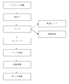
- processing of a workpiece such as a large-diameter silicon wafer represented by a diameter of 300 mm is performed mainly in the following processing steps as shown in FIG.
- the cleaning process and the inspection process between processes are omitted.
- a wire saw cutting process an ingot is cut into a thin plate-like wafer from a block divided into a plurality of pieces.
- a free abrasive slurry in which abrasive grains such as silicon carbide are suspended is supplied to a plurality of wire trains reciprocating at high speed, and the block is pressed against the wire train to which the slurry is adhered while being pressed at a predetermined speed to form a thin plate Cut into shapes.
- a cutting method using a wire in which a fixed abrasive such as diamond is fixed to the surface of the wire by electrodeposition or the like is also employed.
- the outer periphery of the wafer is rounded using a rotating diamond grindstone or the like having a total groove.
- a cast iron upper and lower surface plate to which a load is applied is rotated, and the carrier is held between the upper and lower surface plates.
- a plurality of the chamfered wafers are lapped while being rotated.
- the wrapped wafer is immersed in a high temperature sodium hydroxide aqueous solution or potassium hydroxide aqueous solution to remove the work-affected layer (damage layer) introduced into the front and back surfaces and the chamfered portion.
- a resin pad such as urethane is pressed against the chamfered portion of the wafer with a predetermined pressure to mirror the chamfered portion.
- the above-mentioned etching held by a carrier between the upper and lower surface plates is rotated by rotating the upper and lower surface plates to which a resin pad such as urethane is affixed using a slurry with adjusted pH containing colloidal silica or the like. Then, the edge-polished wafer is polished while rotating, and both surfaces are mirrored simultaneously.
- Patent Document 1 proposes a single-wafer type lapping method for improving deterioration of the wafer shape, which is a problem of lapping processing in which a plurality of conventional sheets are simultaneously processed.
- a pair of ring-shaped surface plates having an outer diameter substantially equal to the radius of the wafer are opposed to each other and pressed from the center to the periphery of the wafer. Wrap both sides of a wafer at the same time.
- the surface plate size is smaller than the wafer diameter, so there is no uneven wear on the surface plate compared to conventional laps where the surface plate outer diameter is larger than the wafer diameter, and the flatness of the wafer is less likely to collapse.
- the surface plate area is smaller than the wafer area, the wear amount of the surface plate is large and the platen is frequently replaced. Moreover, since the slurry to be used is the same as the conventional lapping, it is not possible to reduce the work-affected layer introduced on the wafer surface. Furthermore, since the single sheet processing is performed, the equipment productivity is remarkably inferior compared to the case of processing a plurality of sheets.
- a double-head grinding method employing a grindstone containing abrasive grains such as diamond has been proposed (see Patent Document 2).
- a wafer is inserted into a hole of a resin or metal ring-shaped holder that is thinner than the wafer, and is rotated and held by the engagement between the notch portion of the wafer and the protrusion formed on the holder, and the radius of the wafer is increased.
- the wafers are ground from both sides simultaneously by rotating the grindstones that are almost equal to each other.
- the reason why a tool having an outer diameter substantially equal to the radius of the workpiece to be processed is as follows. That is, when the outer diameter of the tool is larger than the radius of the workpiece, as shown in FIG. 7A, a non-uniform load is applied in the tool surface, so that the surface of the tool 105 is easily inclined with respect to the processing surface of the workpiece 104. This causes the workpiece shape after machining to deteriorate. In order to suppress this, it is necessary to increase the rigidity of the entire apparatus for holding the tool 105, and increasing the tool size leads to an increase in the size of the entire apparatus, which is economically disadvantageous.
- the outer diameter of the tool when the outer diameter of the tool is smaller than the radius of the workpiece, as shown in FIG. 7B, a non-contact portion between the workpiece 104 and the tool 105 (shaded portion in FIG. 7B) is generated. Not satisfied. Therefore, the outer diameter of the tool should be larger than the radius of the workpiece and as small as possible, and it is best that the outer diameter of the tool is almost equal to the radius of the workpiece.
- the size of the surface waviness component called nanotopography greatly affects the yield of device processes.
- the nanotopography of the final product wafer after finish polishing shows irregularities with a wavelength component of about 0.2 to 20 mm, which has a wavelength shorter than that of warp or warp and longer than the surface roughness, and its PV value is 2 It is a very shallow swell component of ⁇ 20 nm.
- This nanotopography affects the flattening and polishing of the film in the STI (Shallow Trench Isolation) process in the device process, and a strict level is required for the silicon wafer as the device substrate along with the refinement of the design rule.
- the nanotopography of the silicon wafer after the final process is generally measured by an optical interference measuring machine.
- the wafer in the process such as the cutting process or the double-head grinding process is non-specular, it cannot be measured by the reflection interference type measuring machine. Therefore, as proposed in Patent Document 3, it is possible to easily measure nanotopography by performing an arithmetic bandpass filter process on a warped shape obtained from a capacitance type measuring machine.
- the PV value of the cross-sectional shape difference between the maximum displacement value and the minimum displacement value
- this is hereinafter referred to as “pseudo nanotopography value”.
- the difference between the surface of the grindstone and the grinding surface of the workpiece is considered as a factor that deteriorates nanotopography.
- an inclination occurs between the grinding surface of the work held and rotated by the holder and the surfaces of the pair of grindstones, local deformation of the work 104 during grinding occurs as shown in FIG. This local deformation is likely to occur at the center of the workpiece where the workpiece 104 and the grindstone 102 are in contact and at the outer periphery of the workpiece where the workpiece 104 and the holder 103 are in contact with each other. This produces a distorted shape.
- Patent Document 4 it is proposed to perform grinding by controlling the relative position between the center of the thickness of the workpiece and / or the center of the support means for supporting the workpiece and the center of the distance between the grinding wheel surfaces of the pair of grinding wheels.
- Patent Document 5 relates to a static pressure support method for front and back surfaces that supports a workpiece in the axial direction.
- a plurality of pockets each have a fluid supply hole, and a static pressure support member that can adjust the static pressure of the fluid for each pocket. It is shown that the swell component is improved by adopting.
- Patent Document 2 described above a means for defining a gap between the holder and the static pressure support member and a static pressure value and rotating the holder with high accuracy is proposed.
- next-generation devices for example, flash memory 1/2 pitch and MPU gate length shift from 32 nm to 20 nm and further to 16 nm, it becomes difficult to satisfy customer requirements with the above-described conventional improvements. It is coming.
- the nanotopography level required for the final product is expected to be 10 nm or less at a wavelength of 10 mm, and this value corresponds to a pseudo nanotopography value of 0.15 ⁇ m in the intermediate product after double-head grinding, as shown in FIG. Further improvement of nanotopography is an issue.
- the present invention has been made in view of the above-described problems, and improves the nanotopography by suppressing local deformation of the wafer during double-head grinding, which causes deterioration of the nanotopography of the wafer, and
- An object is to provide a double-head grinding method and a double-head grinding apparatus that enable stable continuous grinding.
- a pair of ring-shaped grindstones are rotated to face the workpiece, and the workpiece is rotated from the outer peripheral side along the radial direction.
- the difference between the peripheral speed of the outer peripheral portion and the peripheral speed of the inner peripheral portion of the rotating grindstone is not less than 30 m / min and not more than 45 m / min, and
- the workpiece is ground by adjusting the outer diameter and inner diameter of the grindstone and the rotational speed of the grindstone so that the ratio of the difference between the outer peripheral peripheral speed and the inner peripheral peripheral speed is 10% or more.
- Such a method can suppress local deformation of the wafer during grinding and improve nanotopography. Moreover, the self-generated blade action of the grindstone can be promoted, and stable continuous grinding becomes possible.
- a resinoid grindstone or a vitrified grindstone in which diamond abrasive grains having an average particle diameter of 2 ⁇ m to 6 ⁇ m are mixed with a thermosetting resin binder or a porcelain binder as the grindstone. If it does in this way, the self-generated blade action of a grindstone can be promoted more effectively, and stable continuous grinding can be performed more certainly.
- a silicon wafer having a diameter of 300 mm or more can be used as the workpiece.
- the double-head grinding method of the present invention is particularly effective for double-head grinding of silicon wafers having a diameter of 300 mm or more.
- a double-head grinding apparatus comprising a pair of ring-shaped grinding wheels that grind both surfaces simultaneously, and the difference between the peripheral speed of the outer peripheral part and the peripheral speed of the inner peripheral part of the rotating grindstone is 30 m / min or more and 45 m / min
- the outer diameter and inner diameter of the grindstone and the rotational speed of the grindstone are adjusted so that the ratio of the difference between the outer peripheral peripheral speed and the inner peripheral peripheral speed with respect to the outer peripheral peripheral speed is 10% or more.
- Such a double-head grinding apparatus can improve the nanotopography by suppressing local deformation of the wafer during grinding. Moreover, the self-generated blade action of the grindstone can be promoted, and stable continuous grinding can be achieved.
- the grindstone is preferably a resinoid grindstone or vitrified grindstone obtained by mixing diamond abrasive grains having an average particle diameter of 2 ⁇ m to 6 ⁇ m with a thermosetting resin binder or a porcelain binder. If it is such, the self-generated blade action of a grindstone can be accelerated
- the workpiece can be a silicon wafer having a diameter of 300 mm or more.
- the double-head grinding apparatus of the present invention is particularly effective for double-head grinding of silicon wafers having a diameter of 300 mm or more.
- the difference between the peripheral speed of the outer peripheral portion of the rotating grindstone and the peripheral speed of the inner peripheral portion is 30 m / min or more and 45 m / min or less, and the outer peripheral portion with respect to the outer peripheral portion peripheral speed.
- the workpiece is ground by adjusting the outer diameter and inner diameter of the grindstone and the rotational speed of the grindstone so that the ratio of the difference between the peripheral speed and the inner circumferential speed is 10% or more. Local deformation can be suppressed and nanotopography can be improved. Moreover, the self-generated blade action of the grindstone can be promoted, and stable continuous grinding becomes possible.
- the minute distortion of the workpiece that occurs during double-head grinding which causes deterioration of the nanotopography of the final product wafer, is caused by the grinding surface of the workpiece that is held and rotated by the holder and the pair of grinding wheels. This is due to the deviation from the surface, and is particularly likely to occur at the work center where the work and the grindstone come in contact and at the work outer periphery where the work and the holder come into contact. This is thought to be due to the contact area between the grindstone that sandwiches the workpiece from both sides during grinding and the workpiece.
- the contact area between the grindstone and the workpiece relative to the workpiece area can be increased to about 7%. Therefore, it has been conceived that the larger the segment width of the grindstone, that is, the difference between the outer diameter and the inner diameter of the grindstone, the more the deformation of the wafer is suppressed and finally the nanotopography can be improved.
- the grinding wheel wear amount is too larger than the optimum region (region I in FIG. 3)
- the grinding of the workpiece is difficult to proceed because the abrasive grains frequently fall off.
- the abrasive grains are not frequently dropped and are easily clogged. Therefore, in grinding with a grindstone with a self-generated blade due to wear, the abrasive grains are appropriately dropped, and stable continuous grinding is performed in a state where the self-generated blade action in which the next abrasive cutting edge appears is continuously performed. Is preferred. That is, it is necessary to keep the relative peripheral speed of the outer peripheral part and the relative peripheral speed of the inner peripheral part of the rotating grindstone in the peripheral speed region that promotes the optimum self-generated blade action.
- the present inventor repeated further experiments and studies on the outer diameter and inner diameter of the grindstone and the rotational speed, and the difference between the peripheral speed of the outer periphery and the inner speed of the rotating grindstone is 30 m / min or more.
- the outer diameter and inner diameter of the grindstone and the rotation speed of the grindstone are adjusted so that the ratio of the difference between the outer peripheral peripheral speed and the inner peripheral peripheral speed with respect to the outer peripheral peripheral speed is 10% or more.
- FIG. 1 is a schematic view showing an example of the double-head grinding apparatus of the present invention.
- the double-head grinding apparatus 1 mainly includes a ring-shaped holder 3 that supports the workpiece 4 and a pair of grindstones 2 that simultaneously grind both surfaces of the workpiece 4.
- the holder 3 supports the work 4 from the outer peripheral side along the radial direction, and can rotate. Further, a drive gear (not shown) connected to a motor (not shown) is provided, and the holder 3 can be rotated through the drive gear. A protrusion projecting inward is formed on the inner peripheral portion of the holder 3, and engages with a notch formed in the workpiece 4. By engaging the notch of the workpiece 4 with the projection formed on the holder 3, the workpiece 4 can be held in rotation.
- the material of the holder 3 is not particularly limited, and may be alumina ceramics, for example. If the material is made of alumina ceramic as described above, the workability is good and it is difficult to thermally expand even during processing, so that it can be processed with high accuracy.
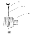
- FIG. 4 shows a schematic diagram of an example of the grindstone 2.
- the grindstone 2 is mainly composed of a segment 2 a and a grindstone body 2 b that are in contact with the grinding surface of the work 4 and grind the work 4.
- the segment 2 a has a predetermined segment width (see FIG. 1). 4 w).
- Each grindstone 2 is connected to a spindle motor (not shown), and can be rotated around the axis at a predetermined rotational speed by driving the spindle motor. Further, the outer diameter of the grindstone 2 can be set to be approximately equal to the radius of the workpiece to be ground.
- the direction of rotation can be controlled so that the pair of grindstones 2 rotate in directions opposite to each other so that the work and the holder are not damaged by applying a force in one direction to the work being ground.
- grinding water required for workpiece grinding can be supplied at a predetermined flow rate from a hollow shaft provided at the center of the grindstone. And while rotating a pair of grindstone 2 facing the workpiece
- the peripheral speed difference between the outer peripheral portion and the inner peripheral portion of the grindstone is the difference between Formula 1 and Formula 2, and is expressed by Formula 3. 2 ⁇ ⁇ ⁇ n ⁇ (AB) (Formula 3)
- AB ⁇ ⁇ ⁇ n ⁇
- the segment width of the grindstone that is, the difference (AB) between the outer radius A and the inner radius B of the grindstone is larger.
- the optimum value is required for the peripheral speed difference (Equation 3) between the outer peripheral portion and the inner peripheral portion of the grinding wheel. This is given by the product of the optimum wheel segment width (AB) and the optimum wheel speed n.
- the ratio of the difference between the outer circumferential speed (Formula 1) and the inner circumferential speed (Formula 2) with respect to the outer circumferential speed (Formula 1) is expressed by Formula 4. 1- (B ⁇ A) (Formula 4)
- Equation 4 the value of the ratio (B ⁇ A) between the outer peripheral radius and the inner peripheral radius of the grindstone is closer to 1 (100% in percentage display), that is, the smaller the value of Equation 4 is, the better. .
- Equation 4 it is better that the ratio of the outer peripheral radius to the inner peripheral radius (B ⁇ A) of the grindstone is small, and Equation 4 is close to 1 (100% in percentage display). Better. Therefore, there is an allowable minimum value in Equation 4.
- Equation 3 should be in the range of 30 m / min or more and 45 m / min or less, and the allowable minimum value of Equation 4 should be 10% or more. That is, in the double-head grinding apparatus of the present invention, during grinding of a workpiece, the difference between the peripheral speed of the outer peripheral portion of the rotating grindstone and the peripheral speed of the inner peripheral portion is 30 m / min or more and 45 m / min or less and The outer diameter and inner diameter of the grindstone and the rotational speed of the grindstone are adjusted so that the ratio of the difference between the outer peripheral speed and the inner peripheral speed with respect to the speed is 10% or more.
- the deformation of the wafer during grinding can be suppressed and nanotopography can be improved.
- the self-generated blade action of the grindstone can be promoted, and stable and continuous grinding can be achieved.
- the rotational speed of the workpiece is very slow at 20 to 50 rpm relative to the peripheral speed of the outer and inner peripheral parts of the grindstone, so the relative peripheral speed with the grindstone is hardly affected, and the above-mentioned stable continuous grinding is performed. There is no need to consider it as a parameter to do.
- the grindstone 2 is preferably a resinoid grindstone or vitrified grindstone in which diamond abrasive grains having an average particle diameter of 2 ⁇ m to 6 ⁇ m are mixed with a thermosetting resin binder or a porcelain binder. If it is such, the self-generated blade action of a grindstone can be accelerated
- the workpiece can be a silicon wafer having a diameter of 300 mm or more.
- the double-head grinding apparatus of the present invention is a silicon wafer having a diameter of 300 mm or more such as a diameter of 300 mm and a diameter of 450 mm. This is particularly effective for double-head grinding.
- a pair of static pressure support members for supporting the holder 3 in a non-contact manner by the static pressure of the fluid can be provided.
- the static pressure support member includes a holder static pressure portion that supports the holder 3 in a non-contact manner on the outer peripheral side, and a wafer static pressure portion that supports the wafer in a non-contact manner on the inner peripheral side.
- the hole for inserting the drive gear used for rotating the holder 3 and the hole for inserting the grindstone 2 are formed in the static pressure support member.
- Such a static pressure support member is arranged on both sides of the holder, and the holder is supported in a non-contact manner while supplying fluid between the static pressure support member and the holder during double-head grinding, thereby stabilizing the position of the holder that supports the workpiece. And deterioration of the nanotopography can be suppressed.
- the double-head grinding apparatus of the present invention is not particularly limited to the presence or absence of a static pressure support member.
- the holder 3 is used to support from the outer peripheral side along the radial direction of the workpiece 4. At this time, the protrusion of the holder 3 and the notch of the workpiece can be engaged and supported.
- the double-head grinding apparatus 1 includes the above-described static pressure support member
- the holder for supporting the workpiece has a gap between the static pressure support member and the holder between the pair of static pressure support members. In this way, a fluid such as water is supplied from the static pressure support member to support the holder in a non-contact manner.
- the wafer manufacturing method of the present invention is not limited to the presence or absence of this support mechanism.
- the work 4 is rotated by rotating the holder 3 while the work is supported by the holder 3, and a pair of ring-shaped grindstones 2 are opposed to the work 4 and are brought into contact with both surfaces of the work 4. Then, both surfaces of the workpiece 4 are ground simultaneously by feeding the grinding stones facing each other while supplying the grinding water at a predetermined flow rate and gradually reducing the interval.
- the difference between the peripheral speed of the outer peripheral portion of the rotating grindstone 2 and the peripheral speed of the inner peripheral portion is 30 m / min or more and 45 m / min or less, and the outer peripheral portion
- the workpiece is ground by adjusting the outer diameter and inner diameter of the grindstone 2 and the rotational speed of the grindstone 2 so that the ratio of the difference between the outer peripheral speed and the inner peripheral speed with respect to the peripheral speed is 10% or more.
- the double-head grinding method of the present invention is a silicon wafer having a diameter of 300 mm or more such as a diameter of 300 mm and a diameter of 450 mm. This is particularly effective for double-head grinding.
- the pair of grindstones 2 can be rotated in opposite directions so that the work and the holder are not damaged by applying a force in one direction to the work being ground.
- Example 1-3 A double-sided grinding apparatus of the present invention as shown in FIG. 1 was used to double-sided a silicon wafer having a diameter of 300 mm, and the nanotopography of the ground wafer and grinding stability were evaluated.
- the evaluated nanotopography was a pseudo nanotopography value.
- the double-head grinding apparatus used was provided with a static pressure support part.
- the silicon wafer was cut with a wire saw using GC # 2000 slurry, and the grinding amount was 50 ⁇ m.
- the feed rate of the grindstone was 20 ⁇ m per minute per side.
- the load current value of the spindle motor that rotationally drives the grindstone was used as a means for judging stability during grinding.
- this load current value exceeded 20 amperes, or when the difference between the load current values of a pair of grindstones exceeded 5 amperes, it was determined that grinding was abnormal, and in that case, the apparatus was automatically stopped.
- region 5 of the segment large was used so that the segment width
- the grindstone segments were composed of vitrified binder and diamond (SD2000) abrasive grains, and were bonded and arranged in a ring shape at regular intervals as shown in FIG. Grinding was performed by changing the width w of this segment to 10 mm (Example 1), 15 mm (Example 2), and 20 mm (Example 3).
- a segment having a short width was disposed only in the vicinity of the bolt hole. Further, in order to promote the discharge of grinding water and chips, the circumferential interval of the segments was set to 1 to 4 mm, and the thickness of the segments was set to 3 mm. And as shown in Table 1, the outer diameter and inner diameter of the grindstone used in each example and the rotational speed of the grindstone were adjusted, and the difference between the peripheral speed of the outer peripheral portion of the grindstone and the peripheral speed of the inner peripheral portion was 30 m / min. As described above, a plurality of workpieces were continuously ground so that the ratio was 45 m / min or less and the ratio of the difference between the outer peripheral peripheral speed and the inner peripheral peripheral speed with respect to the outer peripheral peripheral speed was 10% or more.
- Example 1-3 the load current value of the spindle motor that rotationally drives the grindstone was 15 amperes or less, and the difference between the load current values of the spindle motor of the pair of grindstones was 2 amperes or less. Further, as shown in Table 1, as the inner peripheral radius B decreases, that is, as the segment width of the grindstone increases, the rotational speed region of the grindstone necessary for stable grinding decreases, and the stable rotational speed region (upper limit value) It can be seen that the difference between the upper limit and the lower limit tends to decrease. This result agrees with an empirical result that a smaller grinding wheel segment width tends to obtain a stable grinding state, and it can be said that the conventional grinding wheel segment width of 3 mm is generally adopted.
- the stable continuous grinding is attained by the difference of the peripheral speed of the outer peripheral part of a rotating grindstone, and the peripheral speed of an inner peripheral part being 30 m / min or more and 45 m / min or less.
- the pseudo nanotopography value of the wafer after grinding was measured using a capacitance type measuring device (SBW-330 Bow / warp, manufactured by Kobelco Kaken Co., Ltd.). This pseudo nanotopography value is obtained by cutting off the wavelength band of the short wavelength period component of 1 mm or less and the long wavelength component of 50 mm or more from the cross-sectional shape data obtained by measurement and performing bandpass filtering.
- the maximum value as a result of the bandpass filtering processing to the cross-sectional warp shape every 45 ° was set as a pseudo nanotopography value.
- Table 1 shows the results of the measured pseudo nanotopography.
- the graphic value is improved, that is, the deformation of the wafer during grinding due to the increase in the grindstone (segment) area tends to be suppressed, and the ratio of the difference between the outer peripheral peripheral speed and the inner peripheral peripheral speed with respect to the outer peripheral peripheral speed is It can be seen that good pseudo-nanotopography can be obtained when the ratio is 10% or more.
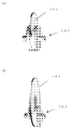
- Example 1 the double-headed wafer in Example 1 was etched by 20 ⁇ m with a 55% aqueous solution of caustic soda and subjected to double-side polishing treatment of about 10 ⁇ m, and nanotopography was measured using Nanomapper (manufactured by KLA-Tencor). The result is shown in FIG. As shown in FIG. 5B, there is no particularly characteristic shape in the wafer surface and it is very smooth. Thus, it can be seen that the result of this nanotopography after the double-side polishing process, which is a subsequent process, is in good agreement with the result of the pseudo-nanotopography value immediately after grinding.
- Example 1-3 The ratio of the difference between the outer peripheral peripheral speed and the inner peripheral peripheral speed with respect to the outer peripheral peripheral speed is 3.8% (Comparative Example 1), 6.3% (Comparative Example 2), and 8.8% (Comparative Example 3).
- the silicon wafer is cut with a wire saw using a GC # 2000 slurry under the same conditions as in Example 1-3, except that the outer diameter and inner diameter of the grindstone are set to be less than 10%, and the rotation speed of the grindstone is further set. Then, grinding was performed at a grinding amount of 50 ⁇ m and a grindstone feed rate of 20 ⁇ m per side per side, and evaluation was performed in the same manner as in Example 1-3. The results are shown in Table 1.
- Example 1 As shown in Table 1, it can be seen that the results of any pseudo nanotopography are worse than the results of Example 1-3. Furthermore, the result of having measured the nanotopography about the thing of the comparative example 1 similarly to Example 1 is shown to FIG. 5 (A). As shown in FIG. 5A, a strong convex shape is generated at the center, and it can be seen that the nanotopography after the double-side polishing process, which is a subsequent process, is deteriorated.
- the present invention is not limited to the above embodiment.
- the above-described embodiment is an exemplification, and the present invention has any configuration that has substantially the same configuration as the technical idea described in the claims of the present invention and exhibits the same function and effect. Are included in the technical scope.
Landscapes
- Engineering & Computer Science (AREA)
- Mechanical Engineering (AREA)
- Mechanical Treatment Of Semiconductor (AREA)
- Grinding Of Cylindrical And Plane Surfaces (AREA)
- Polishing Bodies And Polishing Tools (AREA)
Abstract
本発明は、リング状の一対の砥石を前記ワークに対向して回転させるとともに、前記ワークを径方向に沿って外周側から支持して回転させて前記ワークの両面を同時に研削する両頭研削方法において、回転する前記砥石の外周部の周速と内周部の周速の差が毎分30m以上、毎分45m以下であり、かつ前記外周部周速に対する前記外周部周速と内周部周速の差の割合が10%以上となるように、前記砥石の外径と内径及び前記砥石の回転速度を調整して前記ワークを研削することを特徴とする両頭研削方法である。これにより、ウェーハのナノトポグラフィーを悪化させる要因となる両頭研削中のウェーハの局所的な変形を抑制することによってナノトポグラフィーを改善し、かつ安定した連続研削を可能とする両頭研削方法及び両頭研削装置が提供される。
Description
本発明は、直径300mm以上のシリコンウェーハ等の薄板状のワークの両面を同時に研削する両頭研削方法及び両頭研削装置に関する。
一般的に、例えば直径300mmに代表される大直径のシリコンウェーハ等のワークの加工は、図6に示すように、主に以下の加工工程で実施される。但し、工程間の洗浄工程や検査工程は省略する。
まず、ワイヤソー切断工程では、インゴットが複数に分割されたブロックから薄板状のウェーハに切断する。この際、炭化ケイ素等の砥粒を懸濁させた遊離砥粒スラリを高速で往復走行する複数のワイヤ列に供給し、スラリが付着したワイヤ列にブロックを所定の速度で送りながら押し付けて薄板状に切断する。最近では、ワイヤ表面にダイヤモンド等の固定砥粒を電着等で固着させたワイヤを用いた切断方法も採用される。
まず、ワイヤソー切断工程では、インゴットが複数に分割されたブロックから薄板状のウェーハに切断する。この際、炭化ケイ素等の砥粒を懸濁させた遊離砥粒スラリを高速で往復走行する複数のワイヤ列に供給し、スラリが付着したワイヤ列にブロックを所定の速度で送りながら押し付けて薄板状に切断する。最近では、ワイヤ表面にダイヤモンド等の固定砥粒を電着等で固着させたワイヤを用いた切断方法も採用される。
面取り加工工程では、上記ワイヤソー切断工程で得られたウェーハのチッピングやワレを防止するために、総型溝を有する回転するダイヤモンド砥石等を用いてウェーハ外周の丸め加工が行われる。
ラップ加工工程では、アルミナやジルコニア等の砥粒を懸濁させたスラリを供給しながら、荷重が印加された鋳鉄製の上下定盤を回転させ、この上下定盤の間でキャリアで保持された複数の上記面取りされたウェーハを回転させながらラッピングする。
ラップ加工工程では、アルミナやジルコニア等の砥粒を懸濁させたスラリを供給しながら、荷重が印加された鋳鉄製の上下定盤を回転させ、この上下定盤の間でキャリアで保持された複数の上記面取りされたウェーハを回転させながらラッピングする。
エッチング工程では、高温の水酸化ナトリウム水溶液や水酸化カリウム水溶液中に上記ラップされたウェーハを浸漬し、表裏面や面取り部分に導入された加工変質層(ダメージ層)を除去する。
エッジ研磨工程では、コロイダルシリカ等を含有するpHを調整したスラリを用いて、ウレタン等の樹脂パッドを所定の圧力でウェーハの面取り部に押し付け、面取り部を鏡面化する。
両面研磨工程では、コロイダルシリカ等を含有するpHを調整したスラリを用いて、ウレタン等の樹脂パッドを貼り付けた上下定盤を回転させ、この上下定盤の間でキャリアで保持された上記エッチング及びエッジ研磨されたウェーハを回転させながら研磨し、両面を同時に鏡面化する。
エッジ研磨工程では、コロイダルシリカ等を含有するpHを調整したスラリを用いて、ウレタン等の樹脂パッドを所定の圧力でウェーハの面取り部に押し付け、面取り部を鏡面化する。
両面研磨工程では、コロイダルシリカ等を含有するpHを調整したスラリを用いて、ウレタン等の樹脂パッドを貼り付けた上下定盤を回転させ、この上下定盤の間でキャリアで保持された上記エッチング及びエッジ研磨されたウェーハを回転させながら研磨し、両面を同時に鏡面化する。
最後に、仕上げ研磨工程では、コロイダルシリカ等を含有するpHを調整したスラリを用いて、ウレタン等の樹脂パッドを貼り付けた定盤に、上記両面研磨されたウェーハの裏面から圧力をかけてウェーハの表面のみを接触させ、微細な面粗さや面状態を整える。
ここで、上記のラップ加工は定盤に対するウェーハの占有面積が均一でないため、定盤が偏摩耗しやすく、ウェーハ形状が悪化しやすいため、高平坦度なウェーハの製造には限界がある。また砥粒を微細にする事が難しく、加工変質層深さの低減には不向きである。このような問題を解決するために、上記したラップ加工の代替方式として、枚葉式ラップ方式や両頭研削方式が提案されている。
ここで、上記のラップ加工は定盤に対するウェーハの占有面積が均一でないため、定盤が偏摩耗しやすく、ウェーハ形状が悪化しやすいため、高平坦度なウェーハの製造には限界がある。また砥粒を微細にする事が難しく、加工変質層深さの低減には不向きである。このような問題を解決するために、上記したラップ加工の代替方式として、枚葉式ラップ方式や両頭研削方式が提案されている。
例えば、特許文献1に従来の複数枚を同時処理するラップ加工の問題点であるウェーハ形状の悪化を改善するための枚葉式ラップ方式が提案されている。この方式はウェーハの半径にほぼ等しい外径を持つ一対のリング状の定盤を対向させてウェーハ中心から周辺に至る部分に押圧し、ラップ面とウェーハとの間にスラリを供給しながら、一枚のウェーハの両面を同時にラップする。この方式では、定盤サイズがウェーハ直径より小さいため、ウェーハ直径より定盤外径が大きい従来のラップと比べて定盤の偏摩耗が生じず、ウェーハの平坦度が崩れにくいという利点がある反面、ウェーハ面積に対し定盤面積が小さいため定盤の摩耗量が大きく、定盤交換が頻繁となる欠点がある。また使用するスラリは、従来のラップと同じため、ウェーハ表面に導入される加工変質層の低減は望めない。更に、単数枚処理のため、複数枚処理の場合に比べて設備生産性は著しく劣る。
このような遊離砥粒スラリと定盤を用いたラップ方式の問題点を解決するために、ダイヤモンド等の砥粒を含有する砥石を採用した両頭研削方法が提案されている(特許文献2参照)。この方法では、ウェーハより薄い樹脂製或いは金属製のリング状のホルダの孔にウェーハが挿入され、ウェーハのノッチ部とホルダに形成された突起部との係合により回転保持され、ウェーハの半径にほぼ等しい砥石を対向させて回転させ、ウェーハを両面から同時に研削する。固定砥粒を用いた研削加工であるため、遊離砥粒スラリを用いたラップ加工に比べて高速な加工が可能であり、砥粒径を微細化する事により、より浅い加工変質層を得る事ができ、後工程である両面研磨工程での研磨量削減、研磨時間の短縮が容易となる。
尚、枚葉式ラップ装置及び両頭研削装置において、加工するワークの半径にほぼ等しい外径の工具(上記した定盤及び砥石)が使われる理由は次の通りである。すなわち、ワークの半径に比べ工具の外径が大きい場合、図7(A)に示すように、工具面内で不均一な荷重が加わるためワーク104の加工面に対する工具105の表面が傾きやすく、それが加工後のワーク形状を悪化させる原因となる。これを抑制するためにはその工具105を保持する装置全体の剛性を増大させる必要があり、また工具サイズの大型化は装置全体のサイズの大型化につながり、経済的に不利である。
一方、工具の外径がワークの半径より小さい場合は、図7(B)に示すように、ワーク104と工具105の未接触部分(図7(B)中の斜線部分)が生じるため加工が成立しない。従って、工具の外径はワークの半径より大きく、極力小さい方が良く、ワークの半径にほぼ等しいことが最良である。
以上のように、一般に大直径のシリコンウェーハ等のワークの加工において、高品質な、特により平坦なワークを低コストで製造するためには、従来の遊離砥粒スラリを用いたラップ加工から、固定砥粒砥石を用いた両頭研削加工への移行が有利である。
以上のように、一般に大直径のシリコンウェーハ等のワークの加工において、高品質な、特により平坦なワークを低コストで製造するためには、従来の遊離砥粒スラリを用いたラップ加工から、固定砥粒砥石を用いた両頭研削加工への移行が有利である。
近年、例えば直径300mmに代表される大直径のシリコンウェーハを採用する先端デバイスの製造において、ナノトポグラフィーと呼ばれる表面うねり成分の大小がデバイス工程の歩留まりに大きく影響している。仕上げ研磨後の最終製品ウェーハのナノトポグラフィーは、ソリやWarpより波長が短く、表面粗さより波長の長い、0.2~20mm程度の波長成分の凹凸を示すものであり、そのPV値は2~20nmの極めて浅いうねり成分である。このナノトポグラフィーはデバイス工程におけるSTI(Shallow Trench IsoIation)工程の膜の平坦化研磨に影響し、デバイス基板となるシリコンウェーハに対し、デザインルールの微細化とともに厳しいレベルが要求されている。
最終工程を経たシリコンウェーハのナノトポグラフィーは、一般的には光学干渉式の測定機によって測定される。しかし、切断工程や両頭研削工程等の工程中のウェーハは非鏡面であるため、上記反射干渉式の測定機では計測ができない。そこで、特許文献3に提案されているように、静電容量方式の測定機から得られたソリ形状に算術的バンドパスフィルター処理を行うことにより、簡易的にナノトポグラフィーの測定が可能である。尚、前記簡昜的なナノトポグラフィーの定量値として断面形状のP-V値(変位最大値と最小値の差)を採用し、以下これを「疑似ナノトポグラフィー値」と呼ぶ。
上記の両頭研削において、ナノトポグラフィーを悪化させる要因として、砥石の表面とワークの研削面の乖離が考えられている。ホルダにより保持されて回転駆動されるワークの研削面と一対の砥石の表面に傾きが生じると、図8に示すように、研削中のワーク104の局所的な変形が発生する。この局所的な変形はワーク104と砥石102が接触するワーク中心部、及びワーク104とホルダ103が接触するワーク外周部で起きやすく、ワーク104の表裏で局所的に研削量に差が生じ、微小なゆがみ形状を生じる。
このような研削中のワークの微小なゆがみを抑制するため、従来よりさまざまな改良が検討されてきた。例えば、特許文献4では、ワークの厚さの中心及び/またはワークを支持する支持手段の中心と一対の研削砥石の砥石面間隔の中心との相対位置を制御して研削することが提案されている。また、特許文献5では、ワークを軸方向に支持する表裏面の静圧支持方法に関し、複数のポケットが各々流体の供給孔を具備し、ポケット毎に流体の静圧を調整できる静圧支持部材を採用することにより、うねり成分が改善されることを示している。更に、上述した特許文献2では、ホルダと静圧支持部材の隙間や静圧値を規定し、ホルダを精度よく回転させる手段が提案されている。
しかしながら、次世代デバイスのデザインルール、例えば、フラッシュメモリ1/2ピッチやMPUゲート長が32nmから20nm、さらに16nmへ移行するに伴い、上述した従来の改善では顧客の要求を満足することが難しくなってきている。最終製品に要求されるナノトポグラフィーレベルは10mm波長で10nm以下と予想され、この値は図2に示すように、両頭研削後の中間製品での疑似ナノポトグラフィー値0.15μmに相当し、ナノトポグラフィーの更なる改善が課題となっている。
本発明は前述のような問題に鑑みてなされたもので、ウェーハのナノトポグラフィーを悪化させる要因となる両頭研削中のウェーハの局所的な変形を抑制することによってナノトポグラフィーを改善し、かつ安定した連続研削を可能とする両頭研削方法及び両頭研削装置を提供することを目的とする。
上記目的を達成するために、本発明によれば、リング状の一対の砥石を前記ワークに対向して回転させるとともに、前記ワークを径方向に沿って外周側から支持して回転させて前記ワークの両面を同時に研削する両頭研削方法において、回転する前記砥石の外周部の周速と内周部の周速の差が毎分30m以上、毎分45m以下であり、かつ前記外周部周速に対する前記外周部周速と内周部周速の差の割合が10%以上となるように、前記砥石の外径と内径及び前記砥石の回転速度を調整して前記ワークを研削することを特徴とする両頭研削方法が提供される。
このような方法であれば、研削中のウェーハの局所的な変形を抑制し、ナノトポグラフィーを改善することができる。また、砥石の自生発刃作用を促進でき、安定した連続研削が可能となる。
このとき、前記砥石として、熱硬化樹脂結合材或いは磁器質結合剤に平均粒径が2μmから6μmのダイヤモンド砥粒を混合させたレジノイド砥石或いはビトリファイド砥石を用いることが好ましい。
このようにすれば、砥石の自生発刃作用をより効果的に促進でき、安定した連続研削をより確実に行うことができる。
このようにすれば、砥石の自生発刃作用をより効果的に促進でき、安定した連続研削をより確実に行うことができる。
またこのとき、前記ワークとして、直径300mm以上のシリコンウェーハを用いることができる。
一般に、ウェーハの厚さ/面積の比率が小さくなるに伴い、研削中のワークの変形が顕著となるため、本発明の両頭研削方法は、特に直径300mm以上のシリコンウェーハの両頭研削に有効である。
一般に、ウェーハの厚さ/面積の比率が小さくなるに伴い、研削中のワークの変形が顕著となるため、本発明の両頭研削方法は、特に直径300mm以上のシリコンウェーハの両頭研削に有効である。
また、本発明によれば、少なくとも、ワークを径方向に沿って外周側から支持する自転可能なリング状のホルダと、前記ホルダにより支持された前記ワークに対向して回転することによって前記ワークの両面を同時に研削するリング状の一対の砥石とを具備する両頭研削装置であって、回転する前記砥石の外周部の周速と内周部の周速の差が毎分30m以上、毎分45m以下であり、かつ前記外周部周速に対する前記外周部周速と内周部周速の差の割合が10%以上となるように、前記砥石の外径と内径及び前記砥石の回転速度が調整されたものであることを特徴とする両頭研削装置が提供される。
このような両頭研削装置であれば、研削中のウェーハの局所的な変形を抑制し、ナノトポグラフィーを改善することができるものとなる。また、砥石の自生発刃作用を促進でき、安定した連続研削できるものとなる。
このとき、前記砥石は、熱硬化樹脂結合材或いは磁器質結合剤に平均粒径が2μmから6μmのダイヤモンド砥粒を混合させたレジノイド砥石或いはビトリファイド砥石であることが好ましい。
このようなものであれば、砥石の自生発刃作用をより効果的に促進でき、安定した連続研削をより確実に行うことができるものとなる。
このようなものであれば、砥石の自生発刃作用をより効果的に促進でき、安定した連続研削をより確実に行うことができるものとなる。
またこのとき、前記ワークを、直径300mm以上のシリコンウェーハとすることができる。
一般に、ウェーハの厚さ/面積の比率が小さくなるに伴い、研削中のワークの変形が顕著となるため、本発明の両頭研削装置は、特に直径300mm以上のシリコンウェーハの両頭研削に有効である。
一般に、ウェーハの厚さ/面積の比率が小さくなるに伴い、研削中のワークの変形が顕著となるため、本発明の両頭研削装置は、特に直径300mm以上のシリコンウェーハの両頭研削に有効である。
本発明では、両頭研削装置において、回転する砥石の外周部の周速と内周部の周速の差が毎分30m以上、毎分45m以下であり、かつ前記外周部周速に対する前記外周部周速と内周部周速の差の割合が10%以上となるように、前記砥石の外径と内径及び前記砥石の回転速度を調整して前記ワークを研削するので、研削中のウェーハの局所的な変形を抑制し、ナノトポグラフィーを改善することができる。また、砥石の自生発刃作用を促進でき、安定した連続研削が可能となる。
以下、本発明について実施の形態を説明するが、本発明はこれに限定されるものではない。
最終製品ウェーハのナノトポグラフィーを悪化させる要因となる、両頭研削中に発生するワークの微小なゆがみは、前述のように、ホルダに保持されて回転駆動されるワークの研削面と一対の砥石の表面との乖離に起因しており、特にワークと砥石が接触するワーク中心部、及びワークとホルダが接触するワーク外周部で起きやすい。これは研削中にワークを両面から挟み込む砥石とワークの接触面積が起因していると考えられる。
最終製品ウェーハのナノトポグラフィーを悪化させる要因となる、両頭研削中に発生するワークの微小なゆがみは、前述のように、ホルダに保持されて回転駆動されるワークの研削面と一対の砥石の表面との乖離に起因しており、特にワークと砥石が接触するワーク中心部、及びワークとホルダが接触するワーク外周部で起きやすい。これは研削中にワークを両面から挟み込む砥石とワークの接触面積が起因していると考えられる。
従来、例えば直径300mmのワークを研削する場合、外径160mm、セグメント幅3mmの砥石が一般的に用いられるが、ワーク面積に対する砥石とワークとの接触面積は2%程度しかなく、研削中に一対の砥石で挟まれたワークは容易に変形し得る。
そこで、本発明者はこのような問題を解決すべく鋭意検討を重ねた。そして、本発明者は砥石の外径を変えずに、セグメント幅を拡張することにより、研削中のワークの変形する自由度を抑制し、ワークのゆがみを低減することが可能であると考えた。
そこで、本発明者はこのような問題を解決すべく鋭意検討を重ねた。そして、本発明者は砥石の外径を変えずに、セグメント幅を拡張することにより、研削中のワークの変形する自由度を抑制し、ワークのゆがみを低減することが可能であると考えた。
例えば、直径300mmのワークを研削する場合、外径160mmで、セグメント幅10mmの砥石を用いれば、ワーク面積に対する砥石とワークとの接触面積を7%程度まで増加させる事ができる。従って、砥石のセグメント幅、即ち、砥石外周径と内周径の差が大きいほど、ウェーハの変形が抑制され、最終的にナノトポグラフィーを改善することができることに想到した。
一方、砥石のセグメント幅を拡張すると、回転する砥石の外周部と内周部の相対周速の差が大きくなり、砥石の外周部と内周部の摩耗量の差が大きくなり、研削自体が安定して行われないという問題が発生する。これは以下のような砥石の自生発刃による摩耗機構に起因するものである。即ち、図3に示すように、相対周速が大きい砥石外周部ほど砥石は摩耗しにくくなり、逆に相対周速が小さい砥石内周部ほど摩耗しやすくなる。このため、安定した連続研削を実現するためには、所定の摩耗量範囲に砥石送り速度や砥石回転速度、砥石のセグメント幅を調整する必要がある。
例えば、砥石摩耗量が最適領域より大きすぎる場合は(図3の領域I)、砥粒の脱落が頻繁に起こるためワークの研削が進みにくい。逆に、砥石摩耗が最適領域より小さすぎる場合(図3の領域II)、砥粒の脱落頻度が低く、目詰まりしやすい状態にあると言える。従って、摩耗により自生発刃を伴う砥石による研削では、砥粒が適度に脱落し、次の砥粒切れ刃が現れる自生発刃作用が連続的に行われる状態で安定した連続研削が行われるのが好ましい。
即ち、回転する砥石の外周部の相対周速と内周部の相対周速を最適な自生発刃作用を促進する周速領域に収める必要がある。
即ち、回転する砥石の外周部の相対周速と内周部の相対周速を最適な自生発刃作用を促進する周速領域に収める必要がある。
本発明者はこのような砥石の外周径と内周径、及び回転速度に関してさらに実験及び検討を重ね、回転する砥石の外周部の周速と内周部の周速の差が毎分30m以上、毎分45m以下であり、かつ外周部周速に対する外周部周速と内周部周速の差の割合が10%以上となるように、砥石の外径と内径及び砥石の回転速度を調整することによって、両頭研削中のウェーハの局所的な変形を抑制してナノトポグラフィーを抑制でき、かつ、砥石の自生発刃作用を促進でき安定した連続研削が可能になることを見出し、本発明を完成させた。
図1は本発明の両頭研削装置の一例を示す概略図である。
図1に示すように、両頭研削装置1は、主に、ワーク4を支持するリング状のホルダ3と、ワーク4の両面を同時に研削する一対の砥石2を備えている。
図1に示すように、両頭研削装置1は、主に、ワーク4を支持するリング状のホルダ3と、ワーク4の両面を同時に研削する一対の砥石2を備えている。
ホルダ3は、図1に示すように、ワーク4を径方向に沿って外周側から支持するものであり、自転可能になっている。また、不図示のモータに接続された駆動歯車(不図示)が配設されており、この駆動歯車を通じてホルダ3を自転させることができるようになっている。
ホルダ3の内周部には内側に向かって突出した突起部が形成されており、ワーク4に形成されたノッチと係合するようになっている。このワーク4のノッチとホルダ3に形成された突起部との係合により、ワーク4を回転保持することができるようになっている。
ここで、ホルダ3の材質は特に限定されず、例えば、アルミナセラミクスとすることができる。このように材質がアルミナセラミクスのものであれば、加工性が良く、加工時にも熱膨張し難いため、高精度に加工されたものとすることができる。
ホルダ3の内周部には内側に向かって突出した突起部が形成されており、ワーク4に形成されたノッチと係合するようになっている。このワーク4のノッチとホルダ3に形成された突起部との係合により、ワーク4を回転保持することができるようになっている。
ここで、ホルダ3の材質は特に限定されず、例えば、アルミナセラミクスとすることができる。このように材質がアルミナセラミクスのものであれば、加工性が良く、加工時にも熱膨張し難いため、高精度に加工されたものとすることができる。
また、図1に示すように、一対の砥石2がワークに対向して配置されている。図4に砥石2の一例の概略図を示す。図1、図4に示すように、この砥石2は主にワーク4の研削面に接してワーク4を研削するセグメント2aと砥石本体2bから構成されており、セグメント2aは所定のセグメント幅(図4のw)に形成されている。また、それぞれの砥石2は不図示のスピンドルモータに接続され、このスピンドルモータの駆動によって軸周りに所定の回転速度で回転可能になっている。また、砥石2の外径は研削するワークの半径にほぼ等しい大きさとすることができる。
ここで、研削中のワークに一方向の力が掛かることによってワークやホルダが破損しないように、一対の砥石2がお互いに反対方向に回転するように回転方向を制御することができるようになっている。また、砥石の中心に設けられた中空軸よりワークの研削に必要な研削水を所定の流量で供給することができるようになっている。
そして、一対の砥石2をワーク4に対向して回転させるとともに、ワーク4を径方向に沿って外周側から支持して回転させてワークの両面を同時に研削することができるものとなっている。
そして、一対の砥石2をワーク4に対向して回転させるとともに、ワーク4を径方向に沿って外周側から支持して回転させてワークの両面を同時に研削することができるものとなっている。
ここで、本発明の両頭研削装置によるワークの研削中における砥石の回転速度及び砥石の外周と内周の関係に関して以下に詳細に示す。
砥石の外周部半径(外周部直径/2)をA、砥石の内周部半径(内周部直径/2)をB、砥石の回転速度をnとすると、砥石の外周部と内周部の周速は、各々式1、式2で表される。
2×π×n×A (式1)
2×π×n×B (式2)
砥石の外周部半径(外周部直径/2)をA、砥石の内周部半径(内周部直径/2)をB、砥石の回転速度をnとすると、砥石の外周部と内周部の周速は、各々式1、式2で表される。
2×π×n×A (式1)
2×π×n×B (式2)
砥石の外周部と内周部の周速差は式1と式2の差であり、式3で表される。
2×π×n×(A―B) (式3)
まず、安定した連続研削を行うためには、最適な自生発刃作用を促進する周速領域で研削する必要がある。そこで、式3の値は小さい方が良い。ここで、式3から外周部半径Aと内周部半径Bの差が小さいほど、また砥石の回転速度nが低いほど、式3の値が小さくなることが分かる。
2×π×n×(A―B) (式3)
まず、安定した連続研削を行うためには、最適な自生発刃作用を促進する周速領域で研削する必要がある。そこで、式3の値は小さい方が良い。ここで、式3から外周部半径Aと内周部半径Bの差が小さいほど、また砥石の回転速度nが低いほど、式3の値が小さくなることが分かる。
但し、前述のように、研削中のワークの変形を抑止するためには砥石のセグメント幅、即ち、砥石の外周部半径Aと内周部半径Bの差(A-B)は大きい方がよく、砥石の外周部と内周部の周速差(式3)には最適値が必要となる。
これは、最適な砥石のセグメント幅(A-B)と、最適な砥石の回転速度nの積で与えられる。
また、外周部周速(式1)に対する、外周部周速(式1)と内周部周速(式2)の差の割合は、式4で表される。
1-(B÷A) (式4)
これは、最適な砥石のセグメント幅(A-B)と、最適な砥石の回転速度nの積で与えられる。
また、外周部周速(式1)に対する、外周部周速(式1)と内周部周速(式2)の差の割合は、式4で表される。
1-(B÷A) (式4)
また、安定研削の観点から、砥石の外周部半径と内周部半径の比(B÷A)の値は1(百分率表示で100%)に近いほど、即ち、式4の値は小さいほど良い。反面、ワークの変形を抑えるという観点からすると、砥石の外周部半径と内周部半径の比(B÷A)の値は小さい方がよく、式4が1(パーセント表示で100%)に近い方が良い。従って、式4には許容最小値が存在する。
本発明者はこの式3の最適値を毎分30m以上、毎分45m以下の範囲内とし、また式4の許容最小値を10%以上とすれば良いことを見出した。
即ち、本発明の両頭研削装置ではワークの研削中において、回転する砥石の外周部の周速と内周部の周速の差が毎分30m以上、毎分45m以下であり、かつ外周部周速に対する外周部周速と内周部周速の差の割合が10%以上となるように、砥石の外径と内径及び前記砥石の回転速度が調整されたものとなっている。
即ち、本発明の両頭研削装置ではワークの研削中において、回転する砥石の外周部の周速と内周部の周速の差が毎分30m以上、毎分45m以下であり、かつ外周部周速に対する外周部周速と内周部周速の差の割合が10%以上となるように、砥石の外径と内径及び前記砥石の回転速度が調整されたものとなっている。
このような両頭研削装置であれば、研削中のウェーハの変形を抑制し、ナノトポグラフィーを改善することができるものとなる。また、砥石の自生発刃作用を促進でき、安定して連続研削できるものとなる。
尚、砥石の外周部と内周部の周速に対し、ワークの回転速度は20~50rpmと非常に遅いため、砥石との相対周速にはほとんど影響せず、上述の安定した連続研削を行うためのパラメータとして考慮する必要はない。
尚、砥石の外周部と内周部の周速に対し、ワークの回転速度は20~50rpmと非常に遅いため、砥石との相対周速にはほとんど影響せず、上述の安定した連続研削を行うためのパラメータとして考慮する必要はない。
このとき、砥石2は、熱硬化樹脂結合材或いは磁器質結合剤に平均粒径が2μmから6μmのダイヤモンド砥粒を混合させたレジノイド砥石或いはビトリファイド砥石であることが好ましい。
このようなものであれば、砥石の自生発刃作用をより効果的に促進でき、安定した連続研削をより確実に行うことができるものとなる。
このようなものであれば、砥石の自生発刃作用をより効果的に促進でき、安定した連続研削をより確実に行うことができるものとなる。
またこのとき、ワークを、直径300mm以上のシリコンウェーハとすることができる。
一般に、ウェーハの厚さ/面積の比率が小さくなるに伴い、研削中のワークの変形が顕著となるため、本発明の両頭研削装置は、例えば直径300mm、直径450mmなどの直径300mm以上のシリコンウェーハの両頭研削に特に有効である。
一般に、ウェーハの厚さ/面積の比率が小さくなるに伴い、研削中のワークの変形が顕著となるため、本発明の両頭研削装置は、例えば直径300mm、直径450mmなどの直径300mm以上のシリコンウェーハの両頭研削に特に有効である。
また、ホルダ3を流体の静圧により非接触支持する一対の静圧支持部材(不図示)を設けることができる。この静圧支持部材は、外周側にホルダ3を非接触支持するホルダ静圧部と、内周側にウェーハを非接触支持するウェーハ静圧部から構成される。また、静圧支持部材には、ホルダ3を自転させるのに用いられる駆動歯車を挿入するための穴や、砥石2を挿入するための穴が形成されている。
このような静圧支持部材をホルダの両側に配設し、両頭研削時に流体を静圧支持部材とホルダ間に供給しながらホルダを非接触支持することにより、ワークを支持するホルダの位置を安定化させることができ、ナノトポグラフィーが悪化するのを抑制することができる。但し、本発明の両頭研削装置では静圧支持部材の有無に特に限定されることはない。
次に本発明の両頭研削方法について説明する。
ここでは、図1に示すような本発明の両頭研削装置1を用いた場合について説明する。
ここでは、図1に示すような本発明の両頭研削装置1を用いた場合について説明する。
まず、ホルダ3を用いて、ワーク4の径方向に沿って外周側から支持する。このとき、ホルダ3の突起部とワークのノッチとを係合して支持することができる。
ここで、両頭研削装置1が、上記した静圧支持部材を具備している場合には、ワークを支持するホルダを、一対の静圧支持部材の間に静圧支持部材とホルダが隙間を有するようにして配置し、静圧支持部材から例えば水などの流体を供給し、ホルダを非接触支持する。
ここで、両頭研削装置1が、上記した静圧支持部材を具備している場合には、ワークを支持するホルダを、一対の静圧支持部材の間に静圧支持部材とホルダが隙間を有するようにして配置し、静圧支持部材から例えば水などの流体を供給し、ホルダを非接触支持する。
このように、流体を静圧支持部材とホルダ間に供給しながらホルダを非接触支持することにより、両頭研削時にワークを支持するホルダの位置を安定化させることができ、ナノトポグラフィーが悪化するのを抑制することができるが、本発明のウェーハの製造方法においてはこの支持機構の有無に限定されることはない。
そして、ホルダ3によりワークを支持した状態でホルダ3を自転させることでワーク4を回転させ、リング状の一対の砥石2をワーク4に対向して回転させながらワーク4の両面にそれぞれ当接させ、研削水を所定の流量で供給しながら対向する砥石を送ってその間隔を徐々に小さくすることにより、ワーク4の両面を同時に研削する。
この際、上記した両頭研削装置での説明と同様に、回転する砥石2の外周部の周速と内周部の周速の差が毎分30m以上、毎分45m以下であり、かつ外周部周速に対する外周部周速と内周部周速の差の割合が10%以上となるように、砥石2の外径と内径及び砥石2の回転速度を調整してワークを研削する。
この際、上記した両頭研削装置での説明と同様に、回転する砥石2の外周部の周速と内周部の周速の差が毎分30m以上、毎分45m以下であり、かつ外周部周速に対する外周部周速と内周部周速の差の割合が10%以上となるように、砥石2の外径と内径及び砥石2の回転速度を調整してワークを研削する。
このような方法であれば、研削中のウェーハの変形を抑制し、ナノトポグラフィーを改善することができる。また、砥石の自生発刃作用を促進でき、安定した連続研削が可能となる。
このように研削が進められ、不図示の定寸装置によってワークが所定の厚さに達したことが認識されたときに、一対の砥石の送りを停止し、砥石を左右に開くことで研削が完了する。
このとき、砥石として、熱硬化樹脂結合材或いは磁器質結合剤に平均粒径が2μmから6μmのダイヤモンド砥粒を混合させたレジノイド砥石或いはビトリファイド砥石を用いることが好ましい。
このようにすれば、砥石の自生発刃作用をより効果的に促進でき、安定した連続研削をより確実に行うことができる。
このように研削が進められ、不図示の定寸装置によってワークが所定の厚さに達したことが認識されたときに、一対の砥石の送りを停止し、砥石を左右に開くことで研削が完了する。
このとき、砥石として、熱硬化樹脂結合材或いは磁器質結合剤に平均粒径が2μmから6μmのダイヤモンド砥粒を混合させたレジノイド砥石或いはビトリファイド砥石を用いることが好ましい。
このようにすれば、砥石の自生発刃作用をより効果的に促進でき、安定した連続研削をより確実に行うことができる。
またこのとき、ワークとして、直径300mm以上のシリコンウェーハを用いることができる。
一般に、ウェーハの厚さ/面積の比率が小さくなるに伴い、研削中のワークの変形が顕著となるため、本発明の両頭研削方法は、例えば直径300mm、直径450mmなどの直径300mm以上のシリコンウェーハの両頭研削に特に有効である。
また、研削中のワークに一方向の力が掛かることによってワークやホルダが破損しないように、一対の砥石2をお互いに反対方向に回転させることができる。
一般に、ウェーハの厚さ/面積の比率が小さくなるに伴い、研削中のワークの変形が顕著となるため、本発明の両頭研削方法は、例えば直径300mm、直径450mmなどの直径300mm以上のシリコンウェーハの両頭研削に特に有効である。
また、研削中のワークに一方向の力が掛かることによってワークやホルダが破損しないように、一対の砥石2をお互いに反対方向に回転させることができる。
以下、本発明の実施例及び比較例を示して本発明をより具体的に説明するが、本発明はこれらに限定されるものではない。
(実施例1-3)
図1に示すような本発明の両頭研削装置を用いて、直径300mmのシリコンウェーハを両頭研削し、研削後のウェーハのナノトポグラフィー、及び研削の安定性を評価した。ここで、評価したナノトポグラフィーは疑似ナノトポグラフィー値とした。また、両頭研削装置は静圧支持部が設けられたものを用いた。また、シリコンウェーハは、GC#2000スラリを用いてワイヤソーで切断し、研削量を50μmとした。また、砥石の送り速度を片側当たり毎分20μmとした。
図1に示すような本発明の両頭研削装置を用いて、直径300mmのシリコンウェーハを両頭研削し、研削後のウェーハのナノトポグラフィー、及び研削の安定性を評価した。ここで、評価したナノトポグラフィーは疑似ナノトポグラフィー値とした。また、両頭研削装置は静圧支持部が設けられたものを用いた。また、シリコンウェーハは、GC#2000スラリを用いてワイヤソーで切断し、研削量を50μmとした。また、砥石の送り速度を片側当たり毎分20μmとした。
またここで、研削中の安定性を判断する手段として、砥石を回転駆動するスピンドルモータの負荷電流値を用いた。この負荷電流値が20アンペアを超えた場合、或いは一対の砥石の負荷電流値の差が5アンペアを超えた場合に研削異常と判断するようにし、その場合には装置を自動停止させた。
また、図4に示すように、砥石のセグメント幅を変えられるように、セグメントの接着領域5を広く取った砥石本体2bを用いた。また、砥石固定用のボルト孔6の部分を砥石のセグメント接着領域5から逃がす形状とした。このようにして異なる幅のセグメントを同一の砥石本体に接着することによりセグメント幅を変更できるようにした。
また、砥石のセグメントはビトリファイド結合材とダイヤモンド(SD2000)砥粒で構成されるものとし、図4に示すように、一定間隔でリング状に接着配置した。このセグメントの幅wを10mm(実施例1)、15mm(実施例2)、20mm(実施例3)と変更させて研削を行った。
また、砥石のセグメントはビトリファイド結合材とダイヤモンド(SD2000)砥粒で構成されるものとし、図4に示すように、一定間隔でリング状に接着配置した。このセグメントの幅wを10mm(実施例1)、15mm(実施例2)、20mm(実施例3)と変更させて研削を行った。
尚、セグメントが砥石取り付け用のボルト孔6に干渉しないようにするため、図4に示すように、ボルト孔付近の部分のみに短い幅のセグメントを配置した。また、研削水や切り粉の排出を促すため、セグメントの周方向の間隔を1~4mmとし、セグメントの厚みを3mmとした。
そして、表1に示すように、各実施例で用いた砥石の外径と内径及び砥石の回転速度を調整し、砥石の外周部の周速と内周部の周速の差が毎分30m以上、毎分45m以下であり、かつ外周部周速に対する外周部周速と内周部周速の差の割合が10%以上となるようにして複数のワークを連続して研削した。
そして、表1に示すように、各実施例で用いた砥石の外径と内径及び砥石の回転速度を調整し、砥石の外周部の周速と内周部の周速の差が毎分30m以上、毎分45m以下であり、かつ外周部周速に対する外周部周速と内周部周速の差の割合が10%以上となるようにして複数のワークを連続して研削した。
その結果、実施例1-3とも砥石を回転駆動するスピンドルモータの負荷電流値は15アンペア以下であり、かつ一対の砥石のスピンドルモータの負荷電流値の差は2アンペア以下と正常であった。
また、表1に示すように、内周部半径Bの減少、即ち、砥石のセグメント幅の増加とともに、安定研削に必要な砥石の回転速度領域が減少し、またその安定回転速度領域(上限値と下限値の差)が縮小する傾向にあることが分かる。この結果は、砥石のセグメント幅は小さい方が安定した研削状態を得やすいという経験的な結果と一致し、従来の砥石セグメント幅3mmが一般的に採用される所以であると言える。
また、表1に示すように、内周部半径Bの減少、即ち、砥石のセグメント幅の増加とともに、安定研削に必要な砥石の回転速度領域が減少し、またその安定回転速度領域(上限値と下限値の差)が縮小する傾向にあることが分かる。この結果は、砥石のセグメント幅は小さい方が安定した研削状態を得やすいという経験的な結果と一致し、従来の砥石セグメント幅3mmが一般的に採用される所以であると言える。
このように、回転する砥石の外周部の周速と内周部の周速の差が毎分30m以上、毎分45m以下とすることによって、安定した連続研削が可能となることが分かる。
また、研削後のウェーハの疑似ナノトポグラフィー値を静電容量式測定機(SBW-330 Bow/warp、コベルコ科研社製)を用いて測定した。この疑似ナノトポグラフィー値は測定して得られるソリ断面形状データに短波長周期成分1mm以下、長波長成分50mm以上の波長帯域をカットオフしてバンドパスフィルタリングすることで得られる。ここで45°おきの断面ソリ形状にバンドパスフィルタリング処理した結果の最大値を疑似ナノトポグラフィー値とした。
また、研削後のウェーハの疑似ナノトポグラフィー値を静電容量式測定機(SBW-330 Bow/warp、コベルコ科研社製)を用いて測定した。この疑似ナノトポグラフィー値は測定して得られるソリ断面形状データに短波長周期成分1mm以下、長波長成分50mm以上の波長帯域をカットオフしてバンドパスフィルタリングすることで得られる。ここで45°おきの断面ソリ形状にバンドパスフィルタリング処理した結果の最大値を疑似ナノトポグラフィー値とした。
測定した疑似ナノトポグラフィーの結果を表1に示す。表1に示すように、後述する比較例1-3と比べて砥石の外周部半径(A=80mm)に対して砥石の内周部半径Bが小さくなる実施例1-3では、疑似ナノトポグラフィー値が改善し、即ち、砥石(セグメント)面積の増大による研削中のウェーハの変形が抑制される傾向があり、外周部周速に対する外周部周速と内周部周速の差の割合が10%以上であれば、良好な疑似ナノトポグラフィーが得られることが分かる。
更に、実施例1における両頭研削後のウェーハを55%苛性ソーダ水溶液で20μmエッチング後、10μm程度の両面研磨処理を行い、Nanomapper(KLA-Tencor社製)を用いてナノトポグラフィーの測定を行った。
その結果を図5(B)に示す。図5(B)に示すように、ウェーハ面内に特に特徴ある形状はなく、非常に平滑である。このように、後工程である両面研磨処理後のこのナノトポグラフィーの結果は、上記した研削直後の疑似ナノトポグラフィー値の結果とよく一致していることが分かる。
その結果を図5(B)に示す。図5(B)に示すように、ウェーハ面内に特に特徴ある形状はなく、非常に平滑である。このように、後工程である両面研磨処理後のこのナノトポグラフィーの結果は、上記した研削直後の疑似ナノトポグラフィー値の結果とよく一致していることが分かる。
(比較例1-3)
外周部周速に対する外周部周速と内周部周速の差の割合が3.8%(比較例1)、6.3%(比較例2)、8.8%(比較例3)と10%未満となるように砥石の外径、内径を設定し、さらに砥石の回転速度を設定した以外、実施例1-3と同様な条件でシリコンウェーハをGC#2000スラリを用いてワイヤソーで切断し、研削量を50μm、砥石の送り速度を片側当たり毎分20μmとして研削し、実施例1-3と同様に評価した。
結果を表1に示す。表1に示すように、いずれの疑似ナノトポグラフィーの結果とも実施例1-3の結果と比べ悪化していることが分かる。
更に、比較例1のものについて、実施例1と同様にしてナノトポグラフィーの測定を行った結果を図5(A)に示す。図5(A)に示すように、中央部に強度の凸部形状が発生しており、後工程である両面研磨処理後のナノトポグラフィーが悪化していることが分かる。
外周部周速に対する外周部周速と内周部周速の差の割合が3.8%(比較例1)、6.3%(比較例2)、8.8%(比較例3)と10%未満となるように砥石の外径、内径を設定し、さらに砥石の回転速度を設定した以外、実施例1-3と同様な条件でシリコンウェーハをGC#2000スラリを用いてワイヤソーで切断し、研削量を50μm、砥石の送り速度を片側当たり毎分20μmとして研削し、実施例1-3と同様に評価した。
結果を表1に示す。表1に示すように、いずれの疑似ナノトポグラフィーの結果とも実施例1-3の結果と比べ悪化していることが分かる。
更に、比較例1のものについて、実施例1と同様にしてナノトポグラフィーの測定を行った結果を図5(A)に示す。図5(A)に示すように、中央部に強度の凸部形状が発生しており、後工程である両面研磨処理後のナノトポグラフィーが悪化していることが分かる。
(比較例4)
砥石の外周部の周速と内周部の周速の差が毎分30m以上、毎分45m以下の範囲内とならない回転速度で砥石を回転させた以外、実施例と同様な条件でシリコンウェーハの研削を行った。
その結果、スピンドルモータの負荷電流値が20アンペアを超えてしまったり、一対の砥石の負荷電流値の差が5アンペアを超えてしまった。そのため、研削を途中で中断し、研削を完了させることができなかった。
砥石の外周部の周速と内周部の周速の差が毎分30m以上、毎分45m以下の範囲内とならない回転速度で砥石を回転させた以外、実施例と同様な条件でシリコンウェーハの研削を行った。
その結果、スピンドルモータの負荷電流値が20アンペアを超えてしまったり、一対の砥石の負荷電流値の差が5アンペアを超えてしまった。そのため、研削を途中で中断し、研削を完了させることができなかった。

なお、本発明は、上記実施形態に限定されるものではない。上記実施形態は例示であり、本発明の特許請求の範囲に記載された技術的思想と実質的に同一な構成を有し、同様な作用効果を奏するものは、いかなるものであっても本発明の技術的範囲に包含される。
Claims (6)
- リング状の一対の砥石を前記ワークに対向して回転させるとともに、前記ワークを径方向に沿って外周側から支持して回転させて前記ワークの両面を同時に研削する両頭研削方法において、
回転する前記砥石の外周部の周速と内周部の周速の差が毎分30m以上、毎分45m以下であり、かつ前記外周部周速に対する前記外周部周速と内周部周速の差の割合が10%以上となるように、前記砥石の外径と内径及び前記砥石の回転速度を調整して前記ワークを研削することを特徴とする両頭研削方法。 - 前記砥石として、熱硬化樹脂結合材或いは磁器質結合剤に平均粒径が2μmから6μmのダイヤモンド砥粒を混合させたレジノイド砥石或いはビトリファイド砥石を用いることを特徴とする請求項1に記載の両頭研削方法。
- 前記ワークとして、直径300mm以上のシリコンウェーハを用いることを特徴とする請求項1又は請求項2に記載の両頭研削方法。
- 少なくとも、ワークを径方向に沿って外周側から支持する自転可能なリング状のホルダと、前記ホルダにより支持された前記ワークに対向して回転することによって前記ワークの両面を同時に研削するリング状の一対の砥石とを具備する両頭研削装置であって、
回転する前記砥石の外周部の周速と内周部の周速の差が毎分30m以上、毎分45m以下であり、かつ前記外周部周速に対する前記外周部周速と内周部周速の差の割合が10%以上となるように、前記砥石の外径と内径及び前記砥石の回転速度が調整されたものであることを特徴とする両頭研削装置。 - 前記砥石は、熱硬化樹脂結合材或いは磁器質結合剤に平均粒径が2μmから6μmのダイヤモンド砥粒を混合させたレジノイド砥石或いはビトリファイド砥石であることを特徴とする請求項4に記載の両頭研削装置。
- 前記ワークは、直径300mm以上のシリコンウェーハであることを特徴とする請求項4又は請求項5に記載の両頭研削装置。
Applications Claiming Priority (2)
| Application Number | Priority Date | Filing Date | Title |
|---|---|---|---|
| JP2011091380A JP5494552B2 (ja) | 2011-04-15 | 2011-04-15 | 両頭研削方法及び両頭研削装置 |
| JP2011-091380 | 2011-04-15 |
Publications (1)
| Publication Number | Publication Date |
|---|---|
| WO2012140842A1 true WO2012140842A1 (ja) | 2012-10-18 |
Family
ID=47009037
Family Applications (1)
| Application Number | Title | Priority Date | Filing Date |
|---|---|---|---|
| PCT/JP2012/002275 Ceased WO2012140842A1 (ja) | 2011-04-15 | 2012-04-02 | 両頭研削方法及び両頭研削装置 |
Country Status (3)
| Country | Link |
|---|---|
| JP (1) | JP5494552B2 (ja) |
| TW (1) | TW201309423A (ja) |
| WO (1) | WO2012140842A1 (ja) |
Cited By (2)
| Publication number | Priority date | Publication date | Assignee | Title |
|---|---|---|---|---|
| CN113396030A (zh) * | 2018-12-27 | 2021-09-14 | 胜高股份有限公司 | 两头磨削方法 |
| CN115995383A (zh) * | 2023-02-28 | 2023-04-21 | 深圳市尚鼎芯科技有限公司 | 一种环式晶圆超薄片减薄方法 |
Families Citing this family (9)
| Publication number | Priority date | Publication date | Assignee | Title |
|---|---|---|---|---|
| DE102013204839A1 (de) * | 2013-03-19 | 2014-09-25 | Siltronic Ag | Verfahren zum Polieren einer Scheibe aus Halbleitermaterial |
| JPWO2015050218A1 (ja) * | 2013-10-02 | 2017-03-09 | 日本碍子株式会社 | 研磨物の製造方法 |
| CN108500397A (zh) * | 2018-06-09 | 2018-09-07 | 盐城哈力动力传动及智能装备产业研究院有限公司 | 一种小模数齿轮去毛刺装置及其加工方法 |
| EP4144480B1 (de) * | 2021-09-01 | 2024-01-31 | Siltronic AG | Verfahren zum schleifen von halbleiterscheiben |
| JP7072180B1 (ja) * | 2021-12-20 | 2022-05-20 | 有限会社サクセス | 半導体結晶ウェハの製造方法および製造装置 |
| CN114227524A (zh) * | 2021-12-30 | 2022-03-25 | 西安奕斯伟材料科技有限公司 | 双面研磨装置和双面研磨方法 |
| CN115723035B (zh) * | 2022-09-08 | 2024-05-28 | 西安奕斯伟材料科技股份有限公司 | 用于监控研磨装置的加工状态的系统、方法及双面研磨装置 |
| CN117161839B (zh) * | 2023-11-01 | 2024-02-06 | 山东有研艾斯半导体材料有限公司 | 一种改善硅抛光片边缘机械损伤的方法 |
| CN119927789A (zh) * | 2025-02-07 | 2025-05-06 | 杭州中欣晶圆半导体股份有限公司 | 晶圆缺口磨损改善改进方法 |
Citations (3)
| Publication number | Priority date | Publication date | Assignee | Title |
|---|---|---|---|---|
| JP2000052209A (ja) * | 1998-08-06 | 2000-02-22 | Nippon Sheet Glass Co Ltd | 両頭平面研削装置およびそれを用いた研削方法 |
| JP2001071272A (ja) * | 1999-09-02 | 2001-03-21 | Shin Etsu Handotai Co Ltd | カップ型砥石および両面同時研削装置並びに両面同時研削方法 |
| JP2002126980A (ja) * | 2000-10-25 | 2002-05-08 | Nippei Toyama Corp | 研削装置 |
-
2011
- 2011-04-15 JP JP2011091380A patent/JP5494552B2/ja active Active
-
2012
- 2012-04-02 WO PCT/JP2012/002275 patent/WO2012140842A1/ja not_active Ceased
- 2012-04-05 TW TW101112079A patent/TW201309423A/zh unknown
Patent Citations (3)
| Publication number | Priority date | Publication date | Assignee | Title |
|---|---|---|---|---|
| JP2000052209A (ja) * | 1998-08-06 | 2000-02-22 | Nippon Sheet Glass Co Ltd | 両頭平面研削装置およびそれを用いた研削方法 |
| JP2001071272A (ja) * | 1999-09-02 | 2001-03-21 | Shin Etsu Handotai Co Ltd | カップ型砥石および両面同時研削装置並びに両面同時研削方法 |
| JP2002126980A (ja) * | 2000-10-25 | 2002-05-08 | Nippei Toyama Corp | 研削装置 |
Cited By (2)
| Publication number | Priority date | Publication date | Assignee | Title |
|---|---|---|---|---|
| CN113396030A (zh) * | 2018-12-27 | 2021-09-14 | 胜高股份有限公司 | 两头磨削方法 |
| CN115995383A (zh) * | 2023-02-28 | 2023-04-21 | 深圳市尚鼎芯科技有限公司 | 一种环式晶圆超薄片减薄方法 |
Also Published As
| Publication number | Publication date |
|---|---|
| TW201309423A (zh) | 2013-03-01 |
| JP2012223838A (ja) | 2012-11-15 |
| JP5494552B2 (ja) | 2014-05-14 |
Similar Documents
| Publication | Publication Date | Title |
|---|---|---|
| JP5494552B2 (ja) | 両頭研削方法及び両頭研削装置 | |
| JP4985451B2 (ja) | ワークの両頭研削装置およびワークの両頭研削方法 | |
| JP6079554B2 (ja) | 半導体ウェーハの製造方法 | |
| CN102205520B (zh) | 双面抛光半导体晶片的方法 | |
| JP4780142B2 (ja) | ウェーハの製造方法 | |
| JP5967040B2 (ja) | 鏡面研磨ウェーハの製造方法 | |
| JP5600867B2 (ja) | 半導体ウェーハの製造方法 | |
| JP2009302409A (ja) | 半導体ウェーハの製造方法 | |
| CN102169821A (zh) | 用于生产半导体晶片的方法 | |
| WO2019146336A1 (ja) | 単結晶4H-SiC成長用種結晶及びその加工方法 | |
| JP2011077413A (ja) | シリコンウェハーの製造方法 | |
| JP2009302410A (ja) | 半導体ウェーハの製造方法 | |
| JP2010021394A (ja) | 半導体ウェーハの製造方法 | |
| JP2010076013A (ja) | 回転砥石の研磨方法および研磨装置、並びに研削砥石およびこれを用いた研削装置 | |
| KR102098260B1 (ko) | 워크의 양두연삭방법 | |
| JP7168113B1 (ja) | ウェーハの両面研磨方法 | |
| KR20150073214A (ko) | 연마물의 제조 방법 | |
| JPH10256203A (ja) | 鏡面仕上げされた薄板状ウェーハの製造方法 | |
| JP2011143477A (ja) | 両面研磨装置用キャリア及びこれを用いた両面研磨装置並びに両面研磨方法 | |
| JP2010017779A (ja) | ウェーハ加工方法 | |
| JP2012035402A (ja) | 研磨加工法 | |
| JP2010153844A (ja) | 活性層用ウェーハの製造方法 | |
| JP2006224266A (ja) | ワイヤソーを用いたインゴット切断方法 | |
| JP2007210054A (ja) | カップ型砥石および両頭研削装置ならびに両頭研削方法 |
Legal Events
| Date | Code | Title | Description |
|---|---|---|---|
| 121 | Ep: the epo has been informed by wipo that ep was designated in this application |
Ref document number: 12770629 Country of ref document: EP Kind code of ref document: A1 |
|
| NENP | Non-entry into the national phase |
Ref country code: DE |
|
| 122 | Ep: pct application non-entry in european phase |
Ref document number: 12770629 Country of ref document: EP Kind code of ref document: A1 |