WO2012140819A1 - 情報再生装置および情報再生方法 - Google Patents
情報再生装置および情報再生方法 Download PDFInfo
- Publication number
- WO2012140819A1 WO2012140819A1 PCT/JP2012/001175 JP2012001175W WO2012140819A1 WO 2012140819 A1 WO2012140819 A1 WO 2012140819A1 JP 2012001175 W JP2012001175 W JP 2012001175W WO 2012140819 A1 WO2012140819 A1 WO 2012140819A1
- Authority
- WO
- WIPO (PCT)
- Prior art keywords
- track
- crosstalk
- amount
- nth
- reproduction
- Prior art date
- Legal status (The legal status is an assumption and is not a legal conclusion. Google has not performed a legal analysis and makes no representation as to the accuracy of the status listed.)
- Ceased
Links
Images












Classifications
-
- G—PHYSICS
- G11—INFORMATION STORAGE
- G11B—INFORMATION STORAGE BASED ON RELATIVE MOVEMENT BETWEEN RECORD CARRIER AND TRANSDUCER
- G11B20/00—Signal processing not specific to the method of recording or reproducing; Circuits therefor
- G11B20/10—Digital recording or reproducing
- G11B20/10009—Improvement or modification of read or write signals
-
- G—PHYSICS
- G11—INFORMATION STORAGE
- G11B—INFORMATION STORAGE BASED ON RELATIVE MOVEMENT BETWEEN RECORD CARRIER AND TRANSDUCER
- G11B20/00—Signal processing not specific to the method of recording or reproducing; Circuits therefor
- G11B20/10—Digital recording or reproducing
- G11B20/10009—Improvement or modification of read or write signals
- G11B20/10046—Improvement or modification of read or write signals filtering or equalising, e.g. setting the tap weights of an FIR filter
-
- G—PHYSICS
- G11—INFORMATION STORAGE
- G11B—INFORMATION STORAGE BASED ON RELATIVE MOVEMENT BETWEEN RECORD CARRIER AND TRANSDUCER
- G11B20/00—Signal processing not specific to the method of recording or reproducing; Circuits therefor
- G11B20/10—Digital recording or reproducing
- G11B20/10009—Improvement or modification of read or write signals
- G11B20/10222—Improvement or modification of read or write signals clock-related aspects, e.g. phase or frequency adjustment or bit synchronisation
-
- G—PHYSICS
- G11—INFORMATION STORAGE
- G11B—INFORMATION STORAGE BASED ON RELATIVE MOVEMENT BETWEEN RECORD CARRIER AND TRANSDUCER
- G11B7/00—Recording or reproducing by optical means, e.g. recording using a thermal beam of optical radiation by modifying optical properties or the physical structure, reproducing using an optical beam at lower power by sensing optical properties; Record carriers therefor
- G11B7/004—Recording, reproducing or erasing methods; Read, write or erase circuits therefor
- G11B7/005—Reproducing
Definitions
- the present invention relates to an apparatus and method for reproducing information from an information recording medium.
- the capacity of the optical disc can be achieved by densifying and layering one layer 25GB in two layers in BD (Blu-ray Disc (trademark) standard) and four layers in 32GB one layer in BDXL (trademark) standard. I am improving.
- crosstalk mixed from an adjacent track located next to a reproduction track is used.
- a crosstalk removing apparatus that generates a component in a pseudo manner and subtracts it from an information signal of a reproduction track to remove crosstalk
- a binarization means that makes a binary decision on a read signal and outputs a binary signal corresponding to an adjacent track
- filter means for generating the crosstalk component from the binary signal, delay means for delaying the binary signal, and subtraction means for subtracting the crosstalk component from the information signal of the reproduction track. It was possible.
- an object of the present invention is to provide a method of virtually generating a crosstalk component in consideration of the frequency and / or the phase shift of the adjacent track and the reproduction track, and removing the influence of the crosstalk from the reproduction signal. .
- the crosstalk component is generated in a pseudo manner in consideration of the frequency and / or the phase shift of the adjacent track and the reproduction track, and the influence of the crosstalk is removed from the reproduction signal to thereby generate the crosstalk from the reproduction signal. It is possible to eliminate the influence of the noise and to improve the reading accuracy.
- Configuration diagram of optical disk reproducing means in the first embodiment of the present invention Diagram of light spots and tracks on an optical disc Diagram showing bit response in playback track Diagram showing bit responses on adjacent tracks
- Configuration diagram of waveform generation means in the first embodiment of the present invention A diagram representing a track on an optical disc Diagram of light spots and tracks on an optical disc Timing chart of delay amount control in the first embodiment of the present invention Timing chart of delay amount control in the first embodiment of the present invention
- Configuration diagram of optical disk reproducing means in the first embodiment of the present invention Second embodiment of optical disc reproducing means according to the present invention Diagram of light spots and tracks on an optical disc Configuration diagram of optical disk reproducing means in the third embodiment of the present invention Diagram showing the phase difference between tracks on an optical disc Configuration diagram of waveform generation means in the third embodiment of the present invention Configuration diagram of optical disk reproducing means in the third embodiment of the present invention
- Optical disk reproducing means according to the fourth embodiment of the present invention Diagram showing detrack on an optical disc Configuration diagram of waveform generation means in the fourth embodiment of the present
- This embodiment is an information reproducing apparatus capable of generating a crosstalk component in a pseudo manner and removing crosstalk in consideration of the frequency shift between an adjacent track and a reproduction track in the crosstalk removal processing in optical disk reproduction. And provide a way.
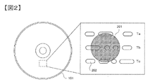
- reproduction track when the laser is irradiated to the reproduction target track (hereinafter referred to as reproduction track) Tb on the optical disc 101, the light spot 201 is a track adjacent to the reproduction track Tb It also affects the track Ta) and the track Tc, which is adjacent to the rear (hereinafter, rear track). As a result, simultaneous reading of the recording marks 202 on the front track Ta and the rear track Tc occurs, and the crosstalk component leaks into the reproduction signal of the reproduction track Tb.
- a response to a 1-bit signal on the reproduction track Tb is represented as a bit response 301 in FIG. 3 according to the optical characteristic and transmission characteristic of the optical pickup.
- responses to 1-bit signals on adjacent tracks Ta and Tb are represented as bit response 401 in FIG.
- the crosstalk component from the adjacent track according to the bit response 401 is superimposed on the reproduction signal.
- a signal having PR (a, b, c, d, e) (a, b, c, d, e: arbitrary real number) which is a PR characteristic 402 close to the bit response 401 is generated
- PR (1, 2, 2, 2, 2) which is the PR characteristic 302 close to the bit response 301. It becomes possible.
- PR characteristic used in the present embodiment is described as PR (1, 2, 2, 2, 1), the present invention is not limited to this, and any coefficient and PR characteristic of a constraint length may be used.
- a reproduction signal read by receiving the reflected light from the disc is subjected to analog processing in an analog front end (hereinafter referred to as AFE) 104, and is input to an AD converter (hereinafter referred to as ADC) 105.
- ADC analog front end
- the reproduction signal digitized by the ADC 105 is waveform-equalized by the waveform equalization unit 106, and is input to the first binarization unit 107 and the first delay unit 108.
- the first delay unit 108 performs delay processing for one track on the output of the waveform equalization unit 106 as described later.
- the output of the waveform equalization unit 106 is the reproduction signal WTc corresponding to the rear track Tc
- the output of the first delay unit 108 is the reproduction signal WTb corresponding to the reproduction track Tb.
- the first binarization unit 107 decodes and outputs the binary signal BTc corresponding to the information recorded on the rear track Tc using, for example, Viterbi decoding.
- the PR characteristic used for Viterbi decoding may be PR (1, 2, 2, 2, 1) which is the PR characteristic 302 close to the bit response 301 or the like.
- the first waveform generation unit 109 uses the characteristics such as PR (a, b, c, d, e) that are PR characteristics 402 close to the bit response 401 to generate a crosstalk signal CTc of the rear track Tc from the binary signal BTc. Are input to the subtraction unit 110.
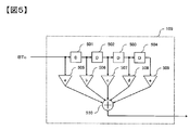
- FIG. 5 shows a configuration example of the first waveform generation unit 109 in FIG.
- the first waveform generation unit 109 which includes a delay unit 501 to 504, multipliers 505 to 509, and an adder 510, forms a convolution operation unit, and performs convolution operation of the PR characteristic 402 of FIG. 4 and the input signal.
- the same configuration may be used for the second waveform generation unit 113.
- the signal generation method is not limited to this configuration.
- the subtraction unit 110 subtracts the crosstalk signal CTc of the rear track Tc and the crosstalk signal CTa of the front track Ta generated in a process described later from the reproduction signal WTb to generate the reproduction signal W of the reproduction track Tb from which the crosstalk is removed.
- the second binarization unit 111 decodes the binary signal BTb corresponding to the information recorded on the reproduction track Tb from the reproduction signal W using Viterbi decoding or the like as in the first binarization unit 107.
- the second delay unit 112 and the demodulation unit 114 are examples of the binary signal BTb corresponding to the information recorded on the reproduction track Tb from the reproduction signal W using Viterbi decoding or the like as in the first binarization unit 107.
- the second delay unit 112 performs delay processing by a delay amount described later so that the output of the second delay unit 112 is delayed by one track with respect to the output of the second binarization unit 111, on the front track Ta. And outputs a binary signal BTa corresponding to the information recorded therein.
- the second waveform generation unit 113 uses the characteristics such as PR (a, b, c, d, e) that are PR characteristics 402 close to the bit response 401 to generate the crosstalk signal CTa of the front track Ta from the binary signal BTa. Are input to the subtraction unit 110.
- the demodulation unit 114 demodulates the output of the second binarization unit 111, and the error correction unit 115 performs error correction processing, and then the output processing unit 116 performs descrambling processing and transmits it to the host 117.
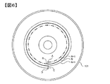
- FIG. 6 shows an example of track configuration on the optical disc 101, where point A to B is the N-1st track, point B to C is the Nth track, point C to D is the N + 1th track, It shall reproduce
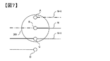
- FIG. 7 shows an enlargement of the vicinity of points A to D in FIG. 6, and when the reproduction processing of the Nth track from the point B is started, the front track Ta on the light spot 201 at the point B is the N-1st track, the reproduction track Tb corresponds to the Nth track, the rear track Tc corresponds to the N + 1th track, and the output of the waveform equalization unit 106 corresponds to the result of reproducing the reproduction track Tb.
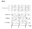
- FIG. 8 shows the relationship between the actual track and the track processed by each part.
- binary signals of the (N + 1) th track and the (N-1) th track are required to remove the crosstalk component of the rear track Tc, but the first binarization unit 107 generates the timing shown in FIG. As such, the binary signal of the (N + 1) th track has not yet been output. Therefore, it is necessary to delay the output of the waveform equalization unit 106 by the first delay unit 108 until the binary signal of the (N + 1) th track is output. Assuming that the delay amount of the first binarizing unit 107 is n1, the necessary delay amount d1 is (number of bits from point B to C) + n1.
- the delay control unit 118 can obtain information on the reproduction position from the microcomputer 119 and dynamically calculate the delay amount of the first delay unit 108 according to the position, so that it is possible to follow the change in the delay amount. I assume.
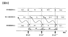
- FIG. 9 shows the relationship of the tracks processed by each part.
- the binary signal of the (N ⁇ 1) th track is required to remove the crosstalk component of the front track Ta at the point B + d1
- the timing is earlier than the point B + d1, which is the necessary timing as shown in FIG.
- the signal is output from the second binarizing unit 111, it is necessary to delay the second delay unit 112.
- the delay amount of the second binarizing unit 111 is n2
- the required delay amount d2 is (number of bits from point B to C) -n2.
- d2 'becomes (the number of bits from point C to D)-n2 when the necessary delay amount when advancing by one track is obtained.
- the delay control unit 118 can obtain information on the reproduction position from the microcomputer 119 and dynamically calculate the delay amount of the second delay unit 111 according to the position, so that it is possible to follow changes in the delay amount. I assume.
- the waveform equalization unit 106 is disposed at the front stage of the first delay unit 108 in this embodiment, the waveform equalization unit 106 may be disposed at the rear stage of the first delay unit 108 or at both the front stage and the rear stage.
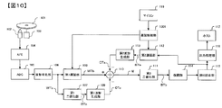
- the output of the second binarization unit 111 is used to generate the crosstalk component of the previous track in this embodiment, the output of the error correction unit 115 may be used as shown in FIG.
- the delay control unit 1001 the delay amount n2 may be the delay amount of the second binarization unit 111, the demodulation unit 114, and the error correction unit 115. The same is applicable to the following embodiments.
- the present embodiment is different from the first embodiment in that signals for three tracks are used in the crosstalk removal processing in the first embodiment, but two tracks are realized in the present embodiment.
- reproduction track a reproduction target track (hereinafter, reproduction track) Tb on the optical disc 101 and a track (hereinafter, front track) Ta adjacent to the reproduction track Tb
- front track Ta a track adjacent to the reproduction track Tb
- simultaneous reading of the recording mark 202 on the rear track Tc occurs, and the crosstalk component leaks into the reproduction signal of the reproduction track Tb.
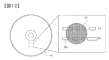
- the tracks Ta and Tb in FIG. 12 are reproduced in order by the optical pickup 102 irradiating a laser onto the optical disc 101 and rotating the spindle motor 103.
- the processing up to the waveform equalization unit 106 is the same as that of the first embodiment, and the output WTb of the waveform equalization unit 106 is input to the subtraction unit 1101.
- the subtraction unit 1101 subtracts the crosstalk signal CTa of the previous track Ta generated in the process described later from the reproduction signal WTb to generate the reproduction signal W of the reproduction track Tb from which the crosstalk has been removed, and inputs it to the binarization unit 1102 .
- the binarization unit 1102 decodes the binary signal BTb corresponding to the information recorded on the reproduction track Tb from the reproduction signal W using Viterbi decoding or the like, and inputs the binary signal BTb to the delay unit 1103 and the demodulation unit 114.
- the delay unit 1103 performs delay processing so that the output of the delay unit 1103 is delayed by one track with respect to the output of the binarization unit 1102, and a binary signal corresponding to the information recorded on the front track Ta. Output BTa.
- the processing of the delay unit 1103 can be realized by the same processing as the second delay unit 112 in the first embodiment.
- the waveform generation unit 1104 generates the crosstalk signal CTa of the front track Ta from the binary signal BTa using characteristics such as PR (a, b, c, d, e) which are PR characteristics 402 close to the bit response 401 Input to the subtraction unit 1101.
- the output processing unit 116 After the demodulation unit 114 demodulates the output of the second binarization unit 111 and the error correction unit 115 performs error correction processing, the output processing unit 116 performs descrambling processing and transmits it to the host 117.
- the present embodiment is different from the first embodiment in that a crosstalk component is generated in a pseudo manner in consideration of not only the frequency deviation of the adjacent track and the reproduction track but also the phase deviation, and the crosstalk is eliminated.
- FIG. 14 shows details of the recording mark 202 of FIG.
- the recording mark 202 is generally recorded spirally on the optical disc 101, and since 1T which is the length of one bit of the recording mark 202 is the same in each track, its phase is shifted in the adjacent track.
- FIG. 14 shows that the front track Ta is shifted by ⁇ 2 and the rear track Tc is shifted by ⁇ 1 with reference to the reproduction track Tb.
- the reproduction apparatus and method of this embodiment using this concept will be described below with reference to FIG. 1
- the first phase difference detection unit 1301 calculates the phase difference ⁇ 1 between the reproduction track Tb and the rear track Tc from the signal processed by the AFE 104 based on the signal detected by the pickup 102.
- This phase difference may be measured from the sync signal position of the reproduction track Tb and the sync signal position of the back track Tc, or a method of acquiring the sub spot signal from the pickup 102 and measuring the distance to the main spot.
- the first phase difference detection unit 1301 in FIG. 13 obtains information from the AFE 104, the present invention is not limited to this, and the information may be obtained from anywhere, such as the pickup 102, the ADC 105, and the waveform equalization unit 106. The same applies to the second phase difference detection unit 1302 described later.
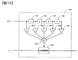
- FIG. 15 shows the configuration of the first waveform generation unit 1303.
- the delay devices 501 to 504, the multipliers 505 to 509, and the adder 510 perform convolution operation of PR (a, b, c, d, e) and the binary signal BTc to obtain a phase.
- the compensation unit 1501 compensates the phase based on the phase difference ⁇ 1 that is the output of the first phase difference detection unit 1301.
- the phase compensation method of the phase compensation unit 1501 can be realized by using, for example, an FIR filter whose characteristic is adjusted such that the phase characteristic in the input signal band is ⁇ 1, but is not limited thereto.
- the crosstalk signal CTc of the back track Tc is generated according to the above configuration, and is input to the subtraction unit 110.
- the second phase difference detection unit 1302 and the second waveform generation unit 1304 are also processed in the same manner as the first phase difference detection unit 1301 and the first waveform generation unit 1303 to generate the crosstalk signal CTa of the front track Ta. , Subtractor 110 is input.
- crosstalk components are generated in a pseudo manner taking into consideration not only the frequency shift of the adjacent track and the playback track but also the phase shift in crosstalk removal processing in optical disk playback. Can be removed.
- the second embodiment can be applied similarly by using the phase difference detection unit 1601 and the waveform generation unit 1602 shown in FIG.
- the present embodiment differs from the first embodiment in that an appropriate crosstalk component is generated and crosstalk is eliminated even when the bit response of the adjacent track changes during reproduction.
- PR ( ⁇ , ⁇ , ⁇ , ⁇ , ⁇ ) ( ⁇ , ⁇ ) is a PR characteristic corresponding to not only steady state PR (a, b, c, d, e) but also the bit response changed during reproduction.
- FIG. 1 What is different from FIG. 1 is a first characteristic detection unit 1701, a second characteristic detection unit 1702, a first waveform generation unit 1703, and a second waveform generation unit 1704.
- the first characteristic detection unit 1701 calculates the detrack amount f1 for the rear track Tc from the signal processed by the AFE 104 based on the signal detected by the pickup 102.
- the detrack amount f1 may be calculated from the tracking error signal of the pickup 102, or may be estimated by evaluating the amount of leakage from the adjacent track when the fixed pattern area is reproduced, but it is not limited.
- the first characteristic detection unit 1701 in FIG. 17 acquires information from the AFE 104, the present invention is not limited to this.
- the first characteristic detection unit 1701 may acquire information from anywhere, such as the pickup 102, the ADC 105, and the waveform equalization unit 106. The same applies to the second characteristic detection unit 1702 described later.
- FIG. 19 shows the configuration of the first waveform generation unit 1703.
- the coefficient generation unit 1901 calculates PR ( ⁇ , ⁇ , ⁇ , ⁇ , ⁇ ) which is a PR characteristic close to the bit response of the back track Tc based on the output f1 of the first characteristic detection unit 1701.
- the delay units 501 to 504, the multipliers 1902 to 1906, and the adder 1907 perform a convolution operation of PR ( ⁇ , ⁇ , ⁇ , ⁇ , ⁇ ) and the binary signal BTc.
- the PR characteristic corresponding to the detrack amount f1 is measured in advance and then recalled, or the signal generated using the calculated PR characteristic is compared with the actual signal and the error is minimized.
- the PR characteristic corresponding to the detrack amount f1 is measured in advance and then recalled, or the signal generated using the calculated PR characteristic is compared with the actual signal and the error is minimized.
- the crosstalk signal CTc of the back track Tc is generated according to the above configuration, and is input to the subtraction unit 110.
- the second characteristic detection unit 1702 and the second waveform generation unit 1704 are also processed in the same manner as the first characteristic detection unit 1701 and the first waveform generation unit 1703, thereby generating the crosstalk signal CTa of the front track Ta and subtracting it. Input to the part 110.
- circuit configuration described above it is possible to generate an appropriate crosstalk component and remove crosstalk even when the bit response of an adjacent track changes during reproduction in crosstalk removal processing in optical disk reproduction. It becomes.
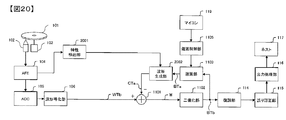
- the characteristic detection unit 2001 and the waveform generation unit 2002 shown in FIG. 20 having the same functions as the first characteristic detection unit 1701 and the first waveform generation unit 1703 are used. The same applies to the second embodiment.
- first phase difference detection unit 1301 of FIG. 13 is used instead of the first characteristic detection unit 1701 to detect a phase difference and generate a coefficient for compensating the phase difference by the coefficient generation unit 1901, this is equivalent to the third embodiment. It is also possible to implement phase compensation with the configuration of the fourth embodiment.
- the present embodiment is different from the first embodiment in that a crosstalk component is generated in a pseudo manner even at the start of reproduction or at the end of reproduction to remove the crosstalk.
- FIG. 21 shows the configuration of the playback apparatus in this embodiment
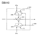
- FIG. 22 shows the configuration of the subtraction unit 2101. What differs from FIG. 1 is the subtraction unit 2101 and the subtraction control unit 2102.
- the pickup 102 When reproduction is desired from the N-th track, the pickup 102 is moved to jump to the (N-1) -th track (2301). Since the crosstalk signal CTa and the crosstalk signal CTc are not generated in the first track after reproduction is started, the subtraction control unit 2102 outputs the switch control signal 2103 based on the information on the reproduction track acquired from the microcomputer 119, and the switch is switched The output of the switch 2202 and the switch 2203 of the subtraction unit 2101 is switched to 0 based on the control signal 2103 (2302), and a reproduction process for one track is performed (2303).
- the output of the switch 2202 of the subtraction control unit 2102 is 0 based on the switch control signal 2103 and the switch 2203 The output is switched so as to be the crosstalk signal CTc (2304), and a reproduction process for one track is performed (2305). Since the crosstalk signal CTa and the crosstalk signal CTc are generated from the third track after playback is started, the switch 2202 output of the subtraction control unit 2102 is the crosstalk signal CTa and the switch 2203 output based on the switch control signal 2103 Switching is performed so as to become the crosstalk signal CTc (2306), and reproduction processing for one track is performed (2307).
- reproduction is performed up to the N + Kth track (K: natural number)
- reproduction processing is performed up to the N + K + 1st track (2308).
- Example 2 The method applied to Example 2 will be described in the same manner.
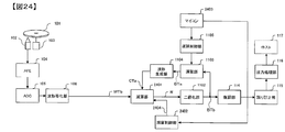
- FIG. 24 shows the configuration of the reproduction apparatus in this embodiment
- FIG. 25 shows the configuration of the subtraction control unit 2402. What differs from FIG. 11 is the subtraction unit 2401 and the subtraction control unit 2402.
- the pickup 102 When reproduction is desired from the N-th track, the pickup 102 is moved to jump to the (N-1) -th track (2601). Since the crosstalk signal CTa is not generated for the first track after reproduction is started, the subtraction control unit 2402 outputs the switch control signal 2403 based on the information of the reproduction track acquired from the microcomputer 119, and based on the switch control signal 2403. Then, the switch 2502 output of the subtraction unit 2401 is switched to 0 (2602), and the reproduction processing for one track is performed (2603).
Landscapes
- Engineering & Computer Science (AREA)
- Signal Processing (AREA)
- Optical Recording Or Reproduction (AREA)
- Signal Processing For Digital Recording And Reproducing (AREA)
Abstract
隣接トラックと再生トラックの周波数および/または位相ずれを考慮して擬似的にクロストーク成分を生成し、再生信号からクロストークの影響を除去する方法を得る。 N+1(N:2以上の自然数)番目トラックの再生において、N番目トラックの再生信号を出力する遅延部と、N+1番目トラックからN番目トラックに対するクロストーク量である第1干渉量と、N+1番目トラックとN番目トラックのずれである第1誤差量に基づいてN+1番目トラックのクロストーク成分を生成する第1波形生成部と、N-1番目トラックからN番目トラックに対するクロストーク量である第2干渉量と、N-1番目トラックとN番目トラックのずれである第2誤差量に基づいてN-1番目トラックのクロストーク成分を生成する第2波形生成部と、前記遅延部出力から前記第1波形生成部出力および前記第2波形生成部出力を減算する波形演算部と、を有することを特徴とする情報再生装置で解決できる。
Description
本発明は、情報記録媒体から情報を再生する、装置および方法に関する。
現在、BD(Blu-ray Disc(商標))規格では1層25GBを2層、またBDXL(商標)規格では1層32GBを4層のように高密度化、多層化することにより光ディスクの容量を向上させている。
今後の更なる高密度、大容量化においては、例えば特許文献1の0002段落に記載のように、「光ディスク再生装置において、光ディスクの記録密度を高めるためトラックピッチを狭くすると、再生対象となるトラック(以下「再生トラック」という。)に照射された光スポットが再生トラックに隣接するトラック(以下「隣接トラック」という。)に漏れて、読取信号にクロストーク成分が混入する。そこで、このクロストーク成分を除去するために、隣接トラックから混入してくるクロストーク成分を疑似的・電気的に生成(以下、「複製」という。)し読取信号から減算する」などの技術が挙げられる。
1ビーム方式の光ピックアップを用いてクロストーク除去を小さい回路規模で実現するには、例えば特許文献1の0009段落に記載のように、「再生トラックの隣に位置する隣接トラックから混入するクロストーク成分を疑似的に生成し、再生トラックの情報信号から減算してクロストークを除去するクロストーク除去装置において、読取信号を2値判定し隣接トラックに相当する2値信号を出力する2値化手段と、2値信号からクロストーク成分を生成するフィルタ手段と、2値信号を遅延させる遅延手段と、再生トラックの情報信号からクロストーク成分を減算する減算手段と、を備えて構成」することで可能としていた。
しかし光ディスクでは螺旋状にトラックを形成するため、隣接トラックと再生トラックの周波数および/または位相ずれが問題となる。よって、この技術を適用する場合、実際に再生信号に含まれているクロストーク成分と二値信号から擬似的に生成したクロストーク成分の間でずれが発生し、正しくクロストーク成分を除去できない。
そこで本発明の目的は、隣接トラックと再生トラックの周波数および/または位相ずれを考慮して擬似的にクロストーク成分を生成し、再生信号からクロストークの影響を除去する方法を提供することにある。
上記課題は、特許請求の範囲に記載の発明により解決される。
本発明によれば、隣接トラックと再生トラックの周波数および/または位相ずれを考慮して擬似的にクロストーク成分を生成し、再生信号からクロストークの影響を除去することで、再生信号からクロストークの影響を除去することが可能となり、読み取り精度を向上させることが可能となる。
以下、本発明の実施例について説明する。
本実施例は、光ディスク再生におけるクロストーク除去処理において、隣接トラックと再生トラックの周波数ずれを考慮した上で擬似的にクロストーク成分を生成し、クロストークを除去することを可能とする情報再生装置および方法を提供する。
まず図2乃至図4を用いて本実施例の概念について説明する。
図2に示すようなトラックピッチの場合、光ディスク101上の再生対象トラック(以下、再生トラック)Tbにレーザを照射すると、光スポット201は再生トラックTbの前に隣接しているトラック(以下、前トラック)Taと、後に隣接しているトラック(以下、後トラック)Tcにも影響する。これにより前トラックTaおよび後トラックTc上の記録マーク202の同時読み出しが発生し、再生トラックTbの再生信号にクロストーク成分が漏れ込む。
このとき、光ピックアップの光学特性や伝送特性により、再生トラックTb上での1ビット信号に対する応答は、図3のビット応答301のように表される。一方、隣接トラックTaおよびTb上での1ビット信号に対する応答は、図4のビット応答401のように表される。このビット応答401に従った隣接トラックからのクロストーク成分が再生信号に重畳することとなる。
クロストーク成分が重畳する場合、ビット応答401に近いPR特性402であるPR(a,b,c,d,e)(a,b,c,d,e:任意の実数)を有する信号を生成し、再生信号から減算することによりクロストークの影響を除去することで、ビット応答301に近いPR特性302であるPR(1,2,2,2,1)のみを用いて再生信号を復号することが可能となる。なお、本実施例において使用するPR特性をPR(1,2,2,2,1)として説明するがこれに限定するものではなく、任意の係数、拘束長のPR特性を用いてもよい。
以下にこの概念を用いた本実施例の再生装置および方法について図1を用いて説明する。
光ピックアップ102が光ディスク101にレーザを照射し、スピンドルモータ103を回転させることで図2のトラックTa、Tb、Tcを順に再生するとする。ディスクからの反射光を受光することで読み取った再生信号は、アナログ・フロント・エンド(Analog Front End:以下、AFE)104においてアナログ処理を行い、ADコンバータ(以下、ADC)105に入力する。ADC105でデジタル化した再生信号は、波形等化部106で波形等化し、第1二値化部107と第1遅延部108に入力する。
第1遅延部108は波形等化部106出力に対して後述するように1トラック分の遅延処理を行う。これにより波形等化部106出力が後トラックTcに対応する再生信号WTcである場合、第1遅延部108出力は再生トラックTbに対応する再生信号WTbとなる。第1二値化部107では、例えばビタビ復号などを用いて、後トラックTc上に記録されている情報に相当する二値信号BTcを復号し出力する。ビタビ復号に使用するPR特性は、ビット応答301に近いPR特性302であるPR(1,2,2,2,1)などを使用すればよい。第1波形生成部109では、ビット応答401に近いPR特性402であるPR(a,b,c,d,e)などの特性を用いて二値信号BTcから、後トラックTcのクロストーク信号CTcを生成し、減算部110へ入力する。
ここで、第1波形生成部109における信号生成方法の例について述べる。
図5は図1における第1波形生成部109の構成例を示す。第1波形生成部109は、遅延器501~504、乗算器505~509、加算器510により畳み込み演算器を構成し、図4のPR特性402と入力信号との畳み込み演算を実施する。第2波形生成部113についても同様の構成を用いればよい。なお、信号生成方法についてはこの構成に限定するものではない。
減算部110では、再生信号WTbから後トラックTcのクロストーク信号CTcと後述の処理で生成する前トラックTaのクロストーク信号CTaを減算、クロストークを除去した再生トラックTbの再生信号Wを生成し、第2二値化部111に入力する。第2二値化部111では、第1二値化部107と同様にビタビ復号などを用いて、再生信号Wから再生トラックTb上に記録されている情報に相当する二値信号BTbを復号し、第2遅延部112と復調部114に入力する。
第2遅延部112は、第2遅延部112出力が第2二値化部111出力に対して1トラック分遅延したものとなるように、後述する遅延量分だけ遅延処理を行い前トラックTa上に記録されている情報に相当する二値信号BTaを出力する。第2波形生成部113では、ビット応答401に近いPR特性402であるPR(a,b,c,d,e)などの特性を用いて二値信号BTaから、前トラックTaのクロストーク信号CTaを生成し、減算部110へ入力する。
その後、復調部114で第2二値化部111出力を復調処理し、誤り訂正部115で誤り訂正処理を実施した後、出力処理部116でデスクランブル処理をし、ホスト117へ送信する。
次に本実施例における第1遅延部108と第2遅延部112の動作について詳細に説明する。
図6は光ディスク101上でのトラックの構成例を示しており、地点AからBをN-1番目トラック、地点BからCまでをN番目トラック、地点CからDまでをN+1番目トラックとし、地点AからDへ順に再生するものとする(N:2以上の自然数)。
図7は図6の地点A~D付近を拡大したもの示し、地点BからN番目トラックの再生処理を開始すると、地点Bでは光スポット201上において前トラックTaはN-1番目トラック、再生トラックTbはN番目トラック、後トラックTcはN+1番目トラック、波形等化部106出力は再生トラックTbを再生した結果に該当する。
まず、第1遅延部108の動作について説明する。
図8は実際のトラックと各部で処理するトラックの関係を示している。地点Bにおいて、後トラックTcのクロストーク成分を除去するためにはN+1番目トラックとN-1番目トラックの二値信号が必要となるが、第1二値化部107では図8に示すタイミングのようにまだN+1番目トラックの二値信号を出力していない。そこで、N+1番目トラックの二値信号が出力されるまで、波形等化部106出力を第1遅延部108で遅延させる必要がある。第1二値化部107の遅延量をn1とすると、必要な遅延量d1は(地点BからCまでのビット数)+n1となる。さらに、1トラック進んだ場合での必要な遅延量をd1’は(地点CからDまでのビット数)+n1となる。このように再生するトラックによって1トラックのビット数が異なることから遅延量も変化する。よって、遅延制御部118ではマイコン119から再生位置の情報を取得し、その位置に応じた第1遅延部108の遅延量を動的に算出することで、遅延量の変化に追従することを可能とする。
次に、第2遅延部111の動作について説明する。
図9は各部で処理するトラックの関係を示している。地点B+d1において、前トラックTaのクロストーク成分を除去するためにはN-1番目トラックの二値信号が必要となるが、図9中示すように必要なタイミングである地点B+d1よりも早いタイミングで第2二値化部111から出力されてしまうため、第2遅延部112で遅延させる必要がある。第2二値化部111の遅延量をn2とすると、必要な遅延量d2は(地点BからCまでのビット数)-n2となる。さらに、1トラック進んだ場合での必要な遅延量をd2’は(地点CからDまでのビット数)-n2となる。このように再生するトラックによって1トラックのビット数が異なることから遅延量も変化する。よって、遅延制御部118ではマイコン119から再生位置の情報を取得し、その位置に応じた第2遅延部111の遅延量を動的に算出することで、遅延量の変化に追従することを可能とする。
以上で説明した回路構成を用いれば、光ディスク再生におけるクロストーク除去処理において、隣接トラックと再生トラックの周波数ずれを考慮した上で擬似的にクロストーク成分を生成し、クロストークを除去することが可能となる。
なお、本実施例は波形等化部106を第1遅延部108の前段に配したが、第1遅延部108の後段、もしくは前段と後段の両方に配してもよい。
さらに、本実施例では前トラックのクロストーク成分を生成するために第2二値化部111出力を用いたが、図10に示すように誤り訂正部115出力を用いて構成してもよい。この際、遅延制御部1001において遅延量n2は第2二値化部111、復調部114、誤り訂正部115の遅延量とすればよい。
これらのことは以降の実施例についても同様に適用可能である。
これらのことは以降の実施例についても同様に適用可能である。
本実施例が実施例1と異なるのは、実施例1がクロストーク除去処理において3トラック分の信号を用いていたのに対して、本実施例では2トラックで実現する点である。
まず図12を用いて本実施例の概念について説明する。
図12に示すように光ディスク101上の再生対象トラック(以下、再生トラック)Tbと再生トラックTbの前に隣接しているトラック(以下、前トラック)Taの間にレーザを照射すると、前トラックTaおよび後トラックTc上の記録マーク202の同時読み出しが発生し、再生トラックTbの再生信号にクロストーク成分が漏れ込む。
よって、前トラックTaのビット応答401に近いPR特性402であるPR(a,b,c,d,e)を有する信号を生成し、再生信号から減算することによりクロストークの影響を除去する。
以下にこの概念を用いた本実施例の再生装置および方法について図11を用いて説明する。
光ピックアップ102が光ディスク101にレーザを照射し、スピンドルモータ103を回転させることで図12のトラックTa、Tbを順に再生するとする。波形等化部106までの処理は実施例1と同一であり、波形等化部106出力WTbを減算部1101に入力する。減算部1101では、後述の処理で生成する前トラックTaのクロストーク信号CTaを再生信号WTbから減算、クロストークを除去した再生トラックTbの再生信号Wを生成し、二値化部1102に入力する。二値化部1102では、ビタビ復号などを用いて、再生信号Wから再生トラックTb上に記録されている情報に相当する二値信号BTbを復号し、遅延部1103と復調部114に入力する。
遅延部1103は、遅延部1103出力が二値化部1102出力に対して1トラック分遅延したものとなるように遅延処理を行い、前トラックTa上に記録されている情報に相当する二値信号BTaを出力する。遅延部1103の処理は実施例1における第2遅延部112と同様の処理で実現できる。波形生成部1104では、ビット応答401に近いPR特性402であるPR(a,b,c,d,e)などの特性を用いて二値信号BTaから、前トラックTaのクロストーク信号CTaを生成し、減算部1101へ入力する。
復調部114で第2二値化部111出力を復調処理し、誤り訂正部115で誤り訂正処理を実施した後、出力処理部116でデスクランブル処理をし、ホスト117へ送信する。
以上で説明した回路構成を用いれば、光ディスク再生におけるクロストーク除去処理において、隣接トラックと再生トラックの周波数ずれを考慮した上で擬似的にクロストーク成分を生成し、クロストークを除去することが可能となる。
本実施例が実施例1と異なるのは、隣接トラックと再生トラックの周波数ずれだけでなく位相ずれをも考慮した上で擬似的にクロストーク成分を生成し、クロストークを除去する点である。
まず図14を用いて本実施例の概念について説明する。
図14に図2の記録マーク202の詳細を示す。記録マーク202は一般的に光ディスク101上に螺旋状に記録され、記録マーク202の1ビット分の長さである1Tは各トラックで同じであるので、その位相は隣接トラックでずれることになる。図14は再生トラックTbを基準として、前トラックTaがφ2、後トラックTcがφ1ずれている様子を示している。クロストーク成分を生成する際にこの位相差を考慮することで、クロストークを除去の精度を高めることが可能となる。
以下にこの概念を用いた本実施例の再生装置および方法について図13を用いて説明する。図1と相違するのは、第1位相差検出部1301、第2位相差検出部1302、第1波形生成部1303、第2波形生成部1304である。
まず第1位相差検出部1301では、ピックアップ102で検出した信号を基にAFE104で処理された信号から、再生トラックTbと後トラックTcの位相差φ1を算出する。この位相差は、再生トラックTbの同期信号位置と後トラックTcの同期信号位置から測定する、もしくはピックアップ102からサブスポットの信号を取得しメインスポットとの距離を測定するなどの方法が考えられるが、限定するものではない。さらに図13の第1位相差検出部1301はAFE104より情報を取得しているがこれに限定するものではなく、ピックアップ102、ADC105、波形等化部106などどこから取得してもよい。これらのことは後述の第2位相差検出部1302についても同様である。
図15に第1波形生成部1303の構成を示す。第1波形生成部1303では、遅延器501~504、乗算器505~509、加算器510により、PR(a,b,c,d,e)と二値信号BTcの畳み込み演算を実施し、位相補償部1501において第1位相差検出部1301出力である位相差φ1に基づいて位相を補償する。位相補償部1501の位相補償方法には、例えば入力信号帯域における位相特性が-φ1となるように特性を調整したFIRフィルタを用いることで実現可能であるが、これに限定するものではない。
以上の構成により後トラックTcのクロストーク信号CTcを生成し、減算部110へ入力する。
第2位相差検出部1302、第2波形生成部1304についても、第1位相差検出部1301、第1波形生成部1303と同様に処理することで、前トラックTaのクロストーク信号CTaを生成し、減算部110へ入力する。
以上で説明した回路構成を用いれば、光ディスク再生におけるクロストーク除去処理において、隣接トラックと再生トラックの周波数ずれだけでなく位相ずれをも考慮した上で擬似的にクロストーク成分を生成し、クロストークを除去することが可能となる。
なお、本実施例では実施例1について説明したが、図16に示す位相差検出部1601、波形生成部1602を使用することで実施例2についても同様に適用可能である。
本実施例が実施例1と異なるのは、隣接トラックのビット応答が再生中に変化した場合においても適切なクロストーク成分を生成し、クロストークを除去する点である。
まず図18を用いて本実施例の概念について説明する。
サーボの追従が正常でない場合などには、図2の光スポット201が図18の光スポット1801のようにずれてしまうデトラックと呼ばれる現象が発生する。この時、隣接トラックTaおよびTb上での1ビット信号に対する応答は、図4のビット応答401から乖離することになる。よって、定常状態のPR(a,b,c,d,e)だけでなく、再生中に変化したビット応答に対応するPR特性であるPR(α,β,γ,δ,ε)(α,β,γ,δ,ε:任意の実数)を有する信号を生成することで、クロストーク除去の精度を高めることが可能となる。なお、以降デトラックを例に説明するが、デフォーカスやチルトなどの各種外乱に対しても同様に適用することが可能である。
以下にこの概念を用いた本実施例の再生装置および方法について図17を用いて説明する。図1と相違するのは、第1特性検出部1701、第2特性検出部1702、第1波形生成部1703、第2波形生成部1704である。
まず第1特性検出部1701では、ピックアップ102で検出した信号を基にAFE104で処理された信号から、後トラックTcに対するデトラック量f1を算出する。このデトラック量f1は、ピックアップ102のトラッキングエラー信号から算出する、もしくは固定パターン領域を再生した際に隣接トラックから漏れ込む量を評価するなどの方法が考えられるが、限定するものではない。さらに図17の第1特性検出部1701はAFE104より情報を取得しているがこれに限定するものではなく、ピックアップ102、ADC105、波形等化部106などどこから取得してもよい。これらのことは後述の第2特性検出部1702についても同様である。
図19に第1波形生成部1703の構成を示す。第1波形生成部1703では、係数生成部1901において第1特性検出部1701出力f1に基づいて後トラックTcのビット応答に近いPR特性であるPR(α,β,γ,δ,ε)を算出し、遅延器501~504、乗算器1902~1906、加算器1907により、PR(α,β,γ,δ,ε)と二値信号BTcの畳み込み演算を実施する。PR特性の算出方法には、例えばデトラック量f1に対応したPR特性を事前に測定しておき呼び出す、もしくは求めたPR特性を使用して生成した信号と実際の信号を比較し誤差が最小となるようにPR特性を追従させるなどの方法によれば実現可能であるが、これらに限定するものではない。
以上の構成により後トラックTcのクロストーク信号CTcを生成し、減算部110へ入力する。
第2特性検出部1702、第2波形生成部1704についても、第1特性検出部1701、第1波形生成部1703と同様に処理することで、前トラックTaのクロストーク信号CTaを生成し、減算部110へ入力する。
以上で説明した回路構成を用いれば、光ディスク再生におけるクロストーク除去処理において、隣接トラックのビット応答が再生中に変化した場合においても適切なクロストーク成分を生成し、クロストークを除去することが可能となる。
なお、本実施例では実施例1について説明したが、第1特性検出部1701、第1波形生成部1703と同様の機能を持つ、図20に示す特性検出部2001、波形生成部2002を使用することで実施例2についても同様に適用可能である。
さらに、第1特性検出部1701の代わりに図13の第1位相差検出部1301を使用し位相差を検出、位相差を補償する係数を係数生成部1901で生成すれば実施例3と同等の位相補償を実施例4の構成で実施することも可能となる。
本実施例が実施例1と異なるのは、再生開始時や再生終了時においても擬似的にクロストーク成分を生成し、クロストークを除去する点である。
図21に本実施例における再生装置の構成を、図22に減算部2101の構成を示す。図1と相違するのは、減算部2101および減算制御部2102である。
ここで、本実施例の再生動作について図12のフローチャートを用いて説明する。
N番目トラックから再生をしたい場合、ピックアップ102を動かしN-1番目トラックへジャンプする(2301)。再生開始して1トラック目はクロストーク信号CTaおよびクロストーク信号CTcが生成されていないため、減算制御部2102ではマイコン119から取得した再生トラックの情報に基づいてスイッチ制御信号2103を出力し、スイッチ制御信号2103に基づいて減算部2101のスイッチ2202およびスイッチ2203出力が0となるように切り替え(2302)、1トラック分の再生処理を実施する(2303)。再生開始して2トラック目にはクロストーク信号CTcは生成されているがクロストーク信号CTaが生成されていないため、スイッチ制御信号2103に基づいて減算制御部2102のスイッチ2202出力が0、スイッチ2203出力がクロストーク信号CTcとなるように切り替え(2304)、1トラック分の再生処理を実施する(2305)。再生開始して3トラック目以降はクロストーク信号CTaおよびクロストーク信号CTcが生成されているため、スイッチ制御信号2103に基づいて減算制御部2102のスイッチ2202出力がクロストーク信号CTa、スイッチ2203出力がクロストーク信号CTcとなるように切り替え(2306)、1トラック分の再生処理を実施する(2307)。ここで、N+K番目トラック(K:自然数)まで再生するならば、N+K+1番目トラックまで再生処理を実施する(2308)。
同様に実施例2に対して適用する方法について述べる。
図24に本実施例における再生装置の構成を、図25に減算制御部2402の構成を示す。図11と相違するのは、減算部2401および減算制御部2402である。
ここで、本実施例の再生動作について図26のフローチャートを用いて説明する。
N番目トラックから再生をしたい場合、ピックアップ102を動かしN-1番目トラックへジャンプする(2601)。再生開始して1トラック目はクロストーク信号CTaが生成されていないため、減算制御部2402ではマイコン119から取得した再生トラックの情報に基づいてスイッチ制御信号2403を出力し、スイッチ制御信号2403に基づいて減算部2401のスイッチ2502出力が0となるように切り替え(2602)、1トラック分の再生処理を実施する(2603)。再生開始して2トラック目以降はクロストーク信号CTaが生成されているため、スイッチ制御信号2403に基づいて減算制御部2402のスイッチ2502出力がクロストーク信号CTaとなるように切り替え(2604)、1トラック分の再生処理を実施する(2605)。ここで、N+K番目トラック(K:自然数)まで再生するならば、N+K番目トラックまで再生処理を実施する(2606)。
以上で説明した回路構成、処理手順によれば、再生開始時や再生終了時においても擬似的にクロストーク成分を生成し、クロストークを除去することが可能となる。
なお、本実施例では実施例1、実施例2について説明したが、その他の実施例についても同様に適用可能である。
101・・・光ディスク、102・・・ピックアップ、103・・・スピンドルモータ、104・・・AFE、105・・・ADC、106・・・波形等化部、107・・・第1二値化部、108・・・第1遅延部、109・・・第1波形生成部、110・・・減算部、111・・・第2二値化部、112・・・第2遅延部、113・・・第2波形生成部、114・・・復調部、115・・・誤り訂正部、116・・・出力処理部、117・・・ホスト、118・・・遅延制御部、119・・・マイコン、201・・・光スポット、202・・・記録マーク、301・・・ビット応答、302・・・PR特性、401・・・ビット応答、402・・・PR特性、501~504・・・遅延器、505~509・・・乗算器、510・・・加算器、1001・・・遅延制御部、1101・・・減算部、1102・・・二値化部、1103・・・遅延部、1104・・・波形生成部、1105・・・遅延制御部、1301・・・第1位相差検出部、1302・・・第2位相差検出部、1303・・・第1波形生成部、1304・・・第2波形生成部、1501・・・位相補償部、1601・・・位相差検出部、1602・・・波形生成部、1701・・・第1特性検出部、1702・・・第2特性検出部、1703・・・第1波形生成部、1704・・・第2波形生成部、1801・・・光スポット、1901・・・係数生成部、1902~1906・・・乗算器、1907・・・加算器、2001・・・特性検出部、2002・・・波形生成部、2101・・・減算部、2102・・・減算制御部、2103・・・スイッチ制御信号、2201・・・減算部、2202・・・スイッチ、2203・・・スイッチ、2401・・・減算部、2402・・・減算制御部、2403・・・スイッチ制御信号、2501・・・減算部、2502・・・スイッチ
Claims (20)
- N+1(N:2以上の自然数)番目トラックを読み出す情報再生装置において、
N番目トラックの再生信号を出力する遅延部と、
N+1番目トラックからN番目トラックに対するクロストーク量である第1干渉量と、N+1番目トラックとN番目トラックのずれである第1誤差量に基づいてN+1番目トラックのクロストーク成分を生成する第1波形生成部と、
N-1番目トラックからN番目トラックに対するクロストーク量である第2干渉量と、N-1番目トラックとN番目トラックのずれである第2誤差量に基づいてN-1番目トラックのクロストーク成分を生成する第2波形生成部と、
前記遅延部出力から前記第1波形生成部出力および前記第2波形生成部出力を減算する波形演算部と、
を有することを特徴とする情報再生装置。 - 請求項1に記載の情報再生装置において、
N+1番目トラックとN番目トラックに記録されたデータの位相差を検出する第1位相差検出部と、
N-1番目トラックとN番目トラックに記録されたデータの位相差を検出する第2位相差検出部と、を備え、
前記第1誤差量とは前記第1位相差検出部出力であり、
前記第2誤差量とは前記第2位相差検出部出力であることを特徴とする情報再生装置。 - 請求項1に記載の情報再生装置において、
N+1番目トラックからN番目トラックへ混入するクロストーク量を検出する第1特性検出部と、
N-1番目トラックからN番目トラックへ混入するクロストーク量を検出する第2特性検出部と、を備え、
前記第1干渉量とは前記第1特性検出部出力であり、
前記第2干渉量とは前記第2特性検出部出力であることを特徴とする情報再生装置。 - 請求項1乃至3に記載の情報再生装置において、
再生トラックの位置に基づいて前記第1波形生成部出力と0を選択する第1スイッチと、再生トラックの位置に基づいて前記第2波形生成部出力と0を選択する第2スイッチと、を有することを特徴とする情報再生装置。 - 請求項1乃至4に記載の情報再生装置において、
光ディスクにレーザ光を照射し、反射光から信号を読み出すピックアップを備え、
光ディスク上のレーザ光のスポット中心がトラック上を走査することを特徴とする情報再生装置。 - N(N:2以上の自然数)番目トラックとN-1番目トラックの間を読み出す情報再生装置において、
N-1番目トラックからN番目トラックに対するクロストーク量である干渉量と、N-1番目トラックとN番目トラックのずれである誤差量に基づいてN-1番目トラックのクロストーク成分を生成する波形生成部と、
N番目トラックの再生信号から前記波形生成部出力を減算する波形演算部と、
を有することを特徴とする情報再生装置。 - 請求項6に記載の情報再生装置において、
N-1番目トラックとN番目トラックに記録されたデータの位相差を検出する位相差検出部を備え、
前記誤差量とは前記位相差検出部出力であることを特徴とする情報再生装置。 - 請求項6に記載の情報再生装置において、
N-1番目トラックからN番目トラックへ混入するクロストーク量を検出する特性検出部を備え、
前記干渉量とは前記特性検出部出力であることを特徴とする情報再生装置。 - 請求項6乃至8に記載の情報再生装置において、
再生トラックの位置に基づいて前記波形生成部出力と0を選択するスイッチを有することを特徴とする情報再生装置。 - 請求項6乃至9に記載の情報再生装置において、
光ディスクにレーザ光を照射し、反射光から信号を読み出すピックアップを備え、
光ディスク上のレーザ光のスポット中心がN番目トラックとN-1番目トラックの間を走査することを特徴とする情報再生装置。 - N+1(N:2以上の自然数)番目トラックを読み出す情報再生方法において、
N番目トラックの再生信号を出力し、
N+1番目トラックからN番目トラックに対するクロストーク量である第1干渉量と、N+1番目トラックとN番目トラックのずれである第1誤差量に基づいてN+1番目トラックのクロストーク成分を生成し、
N-1番目トラックからN番目トラックに対するクロストーク量である第2干渉量と、N-1番目トラックとN番目トラックのずれである第2誤差量に基づいてN-1番目トラックのクロストーク成分を生成し、
前記N番目トラックの再生信号から前記N+1番目トラックのクロストーク成分および前記N-1番目トラックのクロストーク成分を減算することを特徴とする情報再生方法。 - 請求項11に記載の情報再生方法において、
N+1番目トラックとN番目トラックに記録されたデータの位相差である第1位相差を検出し、
N-1番目トラックとN番目トラックに記録されたデータの位相差である第2位相差を検出し、
前記第1誤差量とは前記第1位相差であり、
前記第2誤差量とは前記第2位相差であることを特徴とする情報再生方法。 - 請求項11に記載の情報再生方法において、
N+1番目トラックからN番目トラックへ混入するクロストーク量である第1クロストーク量を検出し、
N-1番目トラックからN番目トラックへ混入するクロストーク量である第2クロストーク量を検出し、
前記第1干渉量とは前記第1クロストーク量であり、
前記第2干渉量とは前記第2クロストーク量であることを特徴とする情報再生方法。 - 請求項11乃至13に記載の情報再生方法において、
再生トラックの位置に基づいて前記第1波形生成部出力と0を選択し、
再生トラックの位置に基づいて前記第2波形生成部出力と0を選択することを特徴とする情報再生方法。 - 請求項11乃至14に記載の情報再生方法において、
光ディスクにレーザ光を照射し、
光ディスク上のレーザ光のスポット中心がトラック上を走査することを特徴とする情報再生方法。 - N(N:2以上の自然数)番目トラックとN-1番目トラックの間を読み出す情報再生方法において、
N-1番目トラックからN番目トラックに対するクロストーク量である干渉量と、N-1番目トラックとN番目トラックのずれである誤差量に基づいてN-1番目トラックのクロストーク成分を生成し、
N番目トラックの再生信号から前記波形生成部出力を減算することを特徴とする情報再生方法。 - 請求項16に記載の情報再生方法において、
N-1番目トラックとN番目トラックに記録されたデータの位相差を検出し、
前記誤差量とは前記位相差であることを特徴とする情報再生方法。 - 請求項16に記載の情報再生方法において、
N-1番目トラックからN番目トラックへ混入するクロストーク量を検出し、
前記干渉量とは前記検出結果であることを特徴とする情報再生方法。 - 請求項16乃至18に記載の情報再生方法において、
再生トラックの位置に基づいて前記波形生成部出力と0を選択することを特徴とする情報再生方法。 - 請求項16乃至19に記載の情報再生方法において、
光ディスクにレーザ光を照射し、
光ディスク上のレーザ光のスポット中心がN番目トラックとN-1番目トラックの間を走査することを特徴とする情報再生方法。
Applications Claiming Priority (2)
| Application Number | Priority Date | Filing Date | Title |
|---|---|---|---|
| JP2011090635A JP2012226789A (ja) | 2011-04-15 | 2011-04-15 | 情報再生装置および情報再生方法 |
| JP2011-090635 | 2011-04-15 |
Publications (1)
| Publication Number | Publication Date |
|---|---|
| WO2012140819A1 true WO2012140819A1 (ja) | 2012-10-18 |
Family
ID=47009017
Family Applications (1)
| Application Number | Title | Priority Date | Filing Date |
|---|---|---|---|
| PCT/JP2012/001175 Ceased WO2012140819A1 (ja) | 2011-04-15 | 2012-02-22 | 情報再生装置および情報再生方法 |
Country Status (2)
| Country | Link |
|---|---|
| JP (1) | JP2012226789A (ja) |
| WO (1) | WO2012140819A1 (ja) |
Citations (5)
| Publication number | Priority date | Publication date | Assignee | Title |
|---|---|---|---|---|
| JPH07249230A (ja) * | 1994-03-10 | 1995-09-26 | Pioneer Electron Corp | 光ディスク及び光ディスク再生装置 |
| JPH07334931A (ja) * | 1994-06-10 | 1995-12-22 | Pioneer Electron Corp | クロストーク除去装置 |
| JP2002342938A (ja) * | 2001-03-14 | 2002-11-29 | Fujitsu Ltd | データ再生装置 |
| JP2003196840A (ja) * | 2001-12-25 | 2003-07-11 | Fujitsu Ltd | データ再生装置 |
| JP2005332453A (ja) * | 2004-05-19 | 2005-12-02 | Hitachi Ltd | 情報再生装置及び情報再生方法 |
-
2011
- 2011-04-15 JP JP2011090635A patent/JP2012226789A/ja not_active Withdrawn
-
2012
- 2012-02-22 WO PCT/JP2012/001175 patent/WO2012140819A1/ja not_active Ceased
Patent Citations (5)
| Publication number | Priority date | Publication date | Assignee | Title |
|---|---|---|---|---|
| JPH07249230A (ja) * | 1994-03-10 | 1995-09-26 | Pioneer Electron Corp | 光ディスク及び光ディスク再生装置 |
| JPH07334931A (ja) * | 1994-06-10 | 1995-12-22 | Pioneer Electron Corp | クロストーク除去装置 |
| JP2002342938A (ja) * | 2001-03-14 | 2002-11-29 | Fujitsu Ltd | データ再生装置 |
| JP2003196840A (ja) * | 2001-12-25 | 2003-07-11 | Fujitsu Ltd | データ再生装置 |
| JP2005332453A (ja) * | 2004-05-19 | 2005-12-02 | Hitachi Ltd | 情報再生装置及び情報再生方法 |
Also Published As
| Publication number | Publication date |
|---|---|
| JP2012226789A (ja) | 2012-11-15 |
Similar Documents
| Publication | Publication Date | Title |
|---|---|---|
| JP6075379B2 (ja) | 情報再生装置及び情報再生方法 | |
| JP2012079385A (ja) | データ検出装置、再生装置、データ検出方法 | |
| US20110002375A1 (en) | Information reproducing apparatus using adaptive equalizer and adaptive equalization method | |
| JP6504245B2 (ja) | データ検出装置、再生装置、データ検出方法 | |
| US8873358B2 (en) | Skew detection method and optical disc device | |
| JP4184585B2 (ja) | 信号遅延装置、漏れ信号除去装置及び情報処理装置 | |
| US8730776B2 (en) | Recording device and stray light signal component cancellation method | |
| JPWO2017135000A1 (ja) | 情報処理装置、および情報処理方法、並びにプログラム | |
| JP3986647B2 (ja) | 記録情報再生装置 | |
| JP4634991B2 (ja) | 情報再生装置、情報再生方法 | |
| JP2002352438A (ja) | クロストーク除去装置及び情報再生装置 | |
| TW200822101A (en) | Phase difference detecting device, phase difference detecting method, reproducing device, tracking control method | |
| JP2017162537A (ja) | 光ディスク装置 | |
| JP2003223761A (ja) | 等化器、情報記録装置、情報再生装置及び記録媒体 | |
| WO2012140819A1 (ja) | 情報再生装置および情報再生方法 | |
| JP4130727B2 (ja) | 信号遅延装置、漏れ信号除去装置及び情報処理装置 | |
| JP2011060369A (ja) | フィルタ係数制御器 | |
| JP2003168218A (ja) | 再生装置、妨害信号除去方法 | |
| JP6036798B2 (ja) | データ検出装置、再生装置、データ検出方法 | |
| JP4804268B2 (ja) | デジタルpll回路およびデータ再生装置 | |
| US7791991B2 (en) | Information reproducing apparatus, information reproducing method, information reproducing program, and information recording medium | |
| JP4343873B2 (ja) | 波形等化制御回路および波形等化制御方法 | |
| JP2000322744A (ja) | 時間遅延を補償した再生信号検出方法及びその回路 | |
| JP4383270B2 (ja) | 再生信号評価装置、再生信号評価方法および再生信号評価用コンピュータプログラム | |
| JP2006216175A (ja) | Pll回路およびディスク再生装置 |
Legal Events
| Date | Code | Title | Description |
|---|---|---|---|
| 121 | Ep: the epo has been informed by wipo that ep was designated in this application |
Ref document number: 12771548 Country of ref document: EP Kind code of ref document: A1 |
|
| NENP | Non-entry into the national phase |
Ref country code: DE |
|
| 122 | Ep: pct application non-entry in european phase |
Ref document number: 12771548 Country of ref document: EP Kind code of ref document: A1 |