WO2012140777A1 - 手動変速機のシフト判定装置 - Google Patents
手動変速機のシフト判定装置 Download PDFInfo
- Publication number
- WO2012140777A1 WO2012140777A1 PCT/JP2011/059412 JP2011059412W WO2012140777A1 WO 2012140777 A1 WO2012140777 A1 WO 2012140777A1 JP 2011059412 W JP2011059412 W JP 2011059412W WO 2012140777 A1 WO2012140777 A1 WO 2012140777A1
- Authority
- WO
- WIPO (PCT)
- Prior art keywords
- shift
- manual transmission
- driver
- clutch device
- speed
- Prior art date
Links
Images


Classifications
-
- B—PERFORMING OPERATIONS; TRANSPORTING
- B60—VEHICLES IN GENERAL
- B60K—ARRANGEMENT OR MOUNTING OF PROPULSION UNITS OR OF TRANSMISSIONS IN VEHICLES; ARRANGEMENT OR MOUNTING OF PLURAL DIVERSE PRIME-MOVERS IN VEHICLES; AUXILIARY DRIVES FOR VEHICLES; INSTRUMENTATION OR DASHBOARDS FOR VEHICLES; ARRANGEMENTS IN CONNECTION WITH COOLING, AIR INTAKE, GAS EXHAUST OR FUEL SUPPLY OF PROPULSION UNITS IN VEHICLES
- B60K23/00—Arrangement or mounting of control devices for vehicle transmissions, or parts thereof, not otherwise provided for
- B60K23/02—Arrangement or mounting of control devices for vehicle transmissions, or parts thereof, not otherwise provided for for main transmission clutches
-
- F—MECHANICAL ENGINEERING; LIGHTING; HEATING; WEAPONS; BLASTING
- F16—ENGINEERING ELEMENTS AND UNITS; GENERAL MEASURES FOR PRODUCING AND MAINTAINING EFFECTIVE FUNCTIONING OF MACHINES OR INSTALLATIONS; THERMAL INSULATION IN GENERAL
- F16D—COUPLINGS FOR TRANSMITTING ROTATION; CLUTCHES; BRAKES
- F16D48/00—External control of clutches
- F16D48/06—Control by electric or electronic means, e.g. of fluid pressure
-
- F—MECHANICAL ENGINEERING; LIGHTING; HEATING; WEAPONS; BLASTING
- F16—ENGINEERING ELEMENTS AND UNITS; GENERAL MEASURES FOR PRODUCING AND MAINTAINING EFFECTIVE FUNCTIONING OF MACHINES OR INSTALLATIONS; THERMAL INSULATION IN GENERAL
- F16H—GEARING
- F16H61/00—Control functions within control units of change-speed- or reversing-gearings for conveying rotary motion ; Control of exclusively fluid gearing, friction gearing, gearings with endless flexible members or other particular types of gearing
- F16H61/16—Inhibiting or initiating shift during unfavourable conditions, e.g. preventing forward reverse shift at high vehicle speed, preventing engine over speed
-
- F—MECHANICAL ENGINEERING; LIGHTING; HEATING; WEAPONS; BLASTING
- F16—ENGINEERING ELEMENTS AND UNITS; GENERAL MEASURES FOR PRODUCING AND MAINTAINING EFFECTIVE FUNCTIONING OF MACHINES OR INSTALLATIONS; THERMAL INSULATION IN GENERAL
- F16D—COUPLINGS FOR TRANSMITTING ROTATION; CLUTCHES; BRAKES
- F16D2500/00—External control of clutches by electric or electronic means
- F16D2500/30—Signal inputs
- F16D2500/304—Signal inputs from the clutch
- F16D2500/30401—On-off signal indicating the engage or disengaged position of the clutch
-
- F—MECHANICAL ENGINEERING; LIGHTING; HEATING; WEAPONS; BLASTING
- F16—ENGINEERING ELEMENTS AND UNITS; GENERAL MEASURES FOR PRODUCING AND MAINTAINING EFFECTIVE FUNCTIONING OF MACHINES OR INSTALLATIONS; THERMAL INSULATION IN GENERAL
- F16D—COUPLINGS FOR TRANSMITTING ROTATION; CLUTCHES; BRAKES
- F16D2500/00—External control of clutches by electric or electronic means
- F16D2500/30—Signal inputs
- F16D2500/304—Signal inputs from the clutch
- F16D2500/30406—Clutch slip
-
- F—MECHANICAL ENGINEERING; LIGHTING; HEATING; WEAPONS; BLASTING
- F16—ENGINEERING ELEMENTS AND UNITS; GENERAL MEASURES FOR PRODUCING AND MAINTAINING EFFECTIVE FUNCTIONING OF MACHINES OR INSTALLATIONS; THERMAL INSULATION IN GENERAL
- F16D—COUPLINGS FOR TRANSMITTING ROTATION; CLUTCHES; BRAKES
- F16D2500/00—External control of clutches by electric or electronic means
- F16D2500/30—Signal inputs
- F16D2500/308—Signal inputs from the transmission
- F16D2500/3081—Signal inputs from the transmission from the input shaft
- F16D2500/30816—Speed of the input shaft
- F16D2500/30818—Speed change rate of the input shaft
-
- F—MECHANICAL ENGINEERING; LIGHTING; HEATING; WEAPONS; BLASTING
- F16—ENGINEERING ELEMENTS AND UNITS; GENERAL MEASURES FOR PRODUCING AND MAINTAINING EFFECTIVE FUNCTIONING OF MACHINES OR INSTALLATIONS; THERMAL INSULATION IN GENERAL
- F16D—COUPLINGS FOR TRANSMITTING ROTATION; CLUTCHES; BRAKES
- F16D2500/00—External control of clutches by electric or electronic means
- F16D2500/50—Problem to be solved by the control system
- F16D2500/506—Relating the transmission
-
- F—MECHANICAL ENGINEERING; LIGHTING; HEATING; WEAPONS; BLASTING
- F16—ENGINEERING ELEMENTS AND UNITS; GENERAL MEASURES FOR PRODUCING AND MAINTAINING EFFECTIVE FUNCTIONING OF MACHINES OR INSTALLATIONS; THERMAL INSULATION IN GENERAL
- F16D—COUPLINGS FOR TRANSMITTING ROTATION; CLUTCHES; BRAKES
- F16D2500/00—External control of clutches by electric or electronic means
- F16D2500/50—Problem to be solved by the control system
- F16D2500/51—Relating safety
- F16D2500/5104—Preventing failures
-
- F—MECHANICAL ENGINEERING; LIGHTING; HEATING; WEAPONS; BLASTING
- F16—ENGINEERING ELEMENTS AND UNITS; GENERAL MEASURES FOR PRODUCING AND MAINTAINING EFFECTIVE FUNCTIONING OF MACHINES OR INSTALLATIONS; THERMAL INSULATION IN GENERAL
- F16D—COUPLINGS FOR TRANSMITTING ROTATION; CLUTCHES; BRAKES
- F16D2500/00—External control of clutches by electric or electronic means
- F16D2500/70—Details about the implementation of the control system
- F16D2500/71—Actions
- F16D2500/7101—Driver alarm
- F16D2500/7104—Visual alarms
-
- F—MECHANICAL ENGINEERING; LIGHTING; HEATING; WEAPONS; BLASTING
- F16—ENGINEERING ELEMENTS AND UNITS; GENERAL MEASURES FOR PRODUCING AND MAINTAINING EFFECTIVE FUNCTIONING OF MACHINES OR INSTALLATIONS; THERMAL INSULATION IN GENERAL
- F16H—GEARING
- F16H61/00—Control functions within control units of change-speed- or reversing-gearings for conveying rotary motion ; Control of exclusively fluid gearing, friction gearing, gearings with endless flexible members or other particular types of gearing
- F16H61/16—Inhibiting or initiating shift during unfavourable conditions, e.g. preventing forward reverse shift at high vehicle speed, preventing engine over speed
- F16H2061/161—Inhibiting or initiating shift during unfavourable conditions, e.g. preventing forward reverse shift at high vehicle speed, preventing engine over speed by checking feasibility of shifts, i.e. determine if requested shift can be successfully completed and post shift values are in an acceptable range
-
- F—MECHANICAL ENGINEERING; LIGHTING; HEATING; WEAPONS; BLASTING
- F16—ENGINEERING ELEMENTS AND UNITS; GENERAL MEASURES FOR PRODUCING AND MAINTAINING EFFECTIVE FUNCTIONING OF MACHINES OR INSTALLATIONS; THERMAL INSULATION IN GENERAL
- F16H—GEARING
- F16H59/00—Control inputs to control units of change-speed-, or reversing-gearings for conveying rotary motion
- F16H59/36—Inputs being a function of speed
- F16H59/46—Inputs being a function of speed dependent on a comparison between speeds
Definitions
- the present invention relates to a shift determination device for a manual transmission mounted on an automobile or the like.
- the present invention relates to a measure for determining whether or not an appropriate shift operation is performed by a driver.
- a shift lever is movably disposed in a shift gate formed with a gate groove extending in a direction (sometimes referred to as a shift operation direction). Then, after a select operation that operates the shift lever in the select operation direction along the gate groove, a desired gear position is established in the transmission mechanism of the manual transmission by performing a shift operation that operates in one direction of the shift operation direction.
- the manual transmission has a feature that a shift operation to an arbitrary gear stage intended by the driver is possible. That is, it can be said that the manual transmission has a great feature that the degree of freedom in selecting the shift speed is high (the selection of the shift speed depends on the driver's intention).
- misshift when the driver operates the shift lever to switch the shift stage of the transmission mechanism, if the shift operation is incorrect and the driver switches to a shift stage not intended by the driver (hereinafter, this erroneous operation is referred to as a misshift), the clutch It may adversely affect the equipment and engine. In addition, drivability may be deteriorated.
- a shift operation to the first speed is erroneously performed.
- the shift operation to the third speed may be mistakenly performed. If such a misshift occurs, an excessive deceleration torque may be input to the clutch device when the clutch is engaged, or the engine speed may rise rapidly and exceed the allowable speed. Along with this, a shift shock to the deceleration side occurs and drivability deteriorates.
- Patent Document 2 when the expected rotation speed after the shift operation (the input shaft rotation speed of the transmission) is equal to or higher than a predetermined rotation speed, the shift is limited. Yes.
- the present invention has been made in view of the above points, and the object of the present invention is to determine a situation where an appropriate shift operation represented by a misshift is not performed, and to adversely affect the clutch device and the engine. It is an object of the present invention to provide a shift determination device for a manual transmission that can be used to avoid the above-described problem.
- transmission and disconnection of the driving force from the driving source is performed as the clutch device is engaged and released, and a manual shift operation by the driver in a state where the clutch device is released is performed.
- the present invention is directed to a shift determination device for a manual transmission in which any one of a plurality of shift stages can be selected. Based on the input shaft rotation speed of the manual transmission that changes with the manual shift operation by the driver in a state where the clutch device is released, the shift determination device of the manual transmission shifts by the manual shift operation. Shift determination means for determining whether the state in which the gear is selected is a state that allows the clutch device to be engaged or whether the driver should be alerted when the clutch device is engaged. Is provided.
- a change amount per unit time of the input shaft rotation speed of the manual transmission that changes with a manual shift operation by the driver in a state where the clutch device is released is a predetermined amount.
- the change rate threshold is exceeded, it is determined that the clutch device is not allowed to be engaged or that the driver should be alerted when the clutch device is engaged.
- a deviation between the input shaft rotation speed of the manual transmission and the rotation speed of the drive source, which changes with a manual shift operation by the driver in a state where the clutch device is released, is a predetermined value.
- the rotation deviation threshold is exceeded, it is determined that the clutch device is not allowed to be engaged or that the driver should be alerted when the clutch device is engaged.
- the first determination operation described above makes it possible to determine a misshift when the driver has performed a downshift due to a misshift when he / she tried to perform an upshift. For example, when the vehicle starts and performs upshift operations in order from the first gear, a general driver has a relatively low shift operation speed from the neutral position to the shift position that establishes the target gear. When the driver performs a downshift operation for the purpose of vehicle deceleration or the like, the shift operation speed from the neutral position to the shift position that establishes the target shift speed is relatively low (upshift operation speed). Lower than).
- the driver tries to upshift and downshifts due to a misshift, the amount of change per unit time of the input shaft rotation speed of the manual transmission increases rapidly, and the rate of change The threshold will be exceeded.
- the first determination operation it is possible to determine whether or not there is a misshift by determining whether or not the change amount per unit time of the input shaft rotation speed exceeds a predetermined change rate threshold value. It is.
- the rotation speed of the drive source exceeds the allowable rotation speed when the clutch device is engaged, for example, by setting the rotation speed threshold value to the upper limit value of the allowable rotation speed of the drive source. It is possible to determine whether or not there is a situation in which the drive source is present, and this can be used to protect the drive source.
- the third determination operation can determine whether such a situation has occurred, and can be useful for protecting the clutch device.
- the first determination operation is executed with priority over the second determination operation and the third determination operation. It is preferable to keep it.
- the determination operation 1 determination operation as to whether or not the change amount per unit time of the input shaft rotation speed of the manual transmission exceeds a predetermined change rate threshold
- the determination operation 1 determines whether or not the change amount per unit time of the input shaft rotation speed of the manual transmission exceeds a predetermined change rate threshold
- the change amount per unit time of the input shaft rotation speed appears and can be determined). For this reason, it is possible to execute countermeasures according to the determination result at an early stage, which is effective because it is possible to prompt the driver to be alerted at an early stage.
- a warning is given to the driver.
- warning means to emit For example, a warning to a driver by a warning lamp or a warning buzzer can be mentioned.
- the drive source when the deviation between the input shaft rotation speed of the manual transmission and the rotation speed of the drive source exceeds a predetermined rotation deviation threshold, the drive source is set so that the deviation of the rotation speed is equal to or less than the rotation deviation threshold. It is also possible to provide a rotation speed increase control means for executing a rotation speed increase control for increasing the rotation speed.
- the change amount per unit time of the input shaft rotation speed does not exceed a predetermined change rate threshold in the first determination operation, and the input shaft rotation of the manual transmission in the second determination operation.
- the rotation speed increase control means for executing the rotation speed increase control for increasing the rotation speed of the drive source is provided.
- shift determination is performed based on the input shaft rotation speed of the manual transmission that changes with the manual shift operation by the driver.
- FIG. 1 is a diagram illustrating a schematic configuration of a power train mounted on a vehicle according to the embodiment.
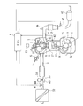
- FIG. 2 is a diagram showing a schematic configuration of the engine and its intake / exhaust system.
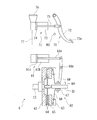
- FIG. 3 is a diagram illustrating a schematic configuration of the clutch device.
- FIG. 4 is a diagram showing an outline of the shift pattern of the 6-speed manual transmission.
- FIG. 5 is a block diagram illustrating a configuration of a control system such as an ECU.
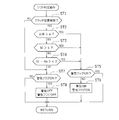
- FIG. 6 is a flowchart showing the procedure of the shift determination operation in the first embodiment.
- FIG. 7 is a flowchart showing the procedure of the shift determination operation in the second embodiment.
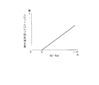
- FIG. 8 is a diagram showing an example of a throttle valve opening correction map.
- FIG. 1 shows a schematic configuration of a power train mounted on a vehicle according to the present embodiment.
- 1 is an engine (drive source)
- MT is a manual transmission
- 6 is a clutch device
- 9 is an ECU (Electronic Control Unit).
- the rotational driving force (torque) generated by the engine 1 is input to the manual transmission MT via the clutch device 6, and an appropriate gear ratio (driver shift) is input by the manual transmission MT.
- the gears are shifted by a gear ratio selected by lever operation and transmitted to the left and right rear wheels (drive wheels) T, T via the propeller shaft PS and the differential gear DF.
- the manual transmission MT mounted on the vehicle according to the present embodiment is a synchronous mesh type manual transmission with six forward speeds and one reverse speed.
- FIG. 2 is a diagram showing a schematic configuration of the engine 1 and its intake and exhaust system. In FIG. 2, only the configuration of one cylinder of the engine 1 is shown.
- the engine 1 in this embodiment is, for example, a four-cylinder gasoline engine, and includes a piston 12 that forms a combustion chamber 11 and a crankshaft 13 that is an output shaft.
- the piston 12 is connected to the crankshaft 13 via a connecting rod 14, and the reciprocating motion of the piston 12 is converted into rotation of the crankshaft 13 by the connecting rod 14.
- a signal rotor 15 having a plurality of protrusions (teeth) 16 on the outer peripheral surface is attached to the crankshaft 13.
- a crank position sensor (engine speed sensor) 81 is disposed near the side of the signal rotor 15.
- the crank position sensor 81 is, for example, an electromagnetic pickup, and generates a pulse-shaped signal (output pulse) corresponding to the protrusion 16 of the signal rotor 15 when the crankshaft 13 rotates.
- the cylinder block 17 of the engine 1 is provided with a water temperature sensor 82 for detecting the engine water temperature (cooling water temperature).
- a spark plug 2 is disposed in the combustion chamber 11 of the engine 1.
- the ignition timing of the spark plug 2 is adjusted by the igniter 21.
- the igniter 21 is controlled by the ECU 9.
- An intake passage 3 and an exhaust passage 4 are connected to the combustion chamber 11 of the engine 1.
- An intake valve 31 is provided between the intake passage 3 and the combustion chamber 11. By opening and closing the intake valve 31, the intake passage 3 and the combustion chamber 11 are communicated or blocked.
- An exhaust valve 41 is provided between the exhaust passage 4 and the combustion chamber 11. By opening and closing the exhaust valve 41, the exhaust passage 4 and the combustion chamber 11 are communicated or blocked. The opening / closing drive of the intake valve 31 and the exhaust valve 41 is performed by each rotation of the intake camshaft and the exhaust camshaft to which the rotation of the crankshaft 13 is transmitted.
- An air cleaner 32, a hot-wire air flow meter 83, an intake air temperature sensor 84 (built in the air flow meter 83), and an electronically controlled throttle valve 33 that adjusts the intake air amount of the engine 1 are disposed in the intake passage 3. ing.
- the throttle valve 33 is driven by a throttle motor 34.
- the opening degree of the throttle valve 33 is detected by a throttle opening degree sensor 85.
- an injector 35 for fuel injection is disposed in the intake passage 3.
- Fuel of a predetermined pressure is supplied from the fuel tank to the injector 35 by a fuel pump, and the fuel is injected into the intake passage 3.
- This injected fuel is mixed with intake air to form an air-fuel mixture and introduced into the combustion chamber 11 of the engine 1.
- the air-fuel mixture (fuel + air) introduced into the combustion chamber 11 passes through the compression stroke of the engine 1 and is then ignited and burned by the spark plug 2.
- the combustion of the air-fuel mixture in the combustion chamber 11 causes the piston 12 to reciprocate and the crankshaft 13 to rotate.
- Two three-way catalysts 42 and 43 are disposed in the exhaust passage 4 of the engine 1. These three-way catalysts 42 and 43 have an O 2 storage function (oxygen storage function) for storing (storing) oxygen, and it is assumed that the air-fuel ratio has deviated from the stoichiometric air-fuel ratio to some extent by this oxygen storage function. In addition, HC, CO and NOx can be purified.
- O 2 storage function oxygen storage function
- HC, CO and NOx can be purified.
- An A / F sensor (air-fuel ratio sensor) 86 is provided upstream of the upstream three-way catalyst 42 in the exhaust passage 4, and an oxygen sensor (O 2 sensor) 87 is provided upstream of the downstream three-way catalyst 43. Each is arranged.
- FIG. 3 shows a schematic configuration of the clutch device 6.
- the clutch device 6 includes a clutch mechanism 60, a clutch pedal 70, a clutch master cylinder 71, and a clutch release cylinder 61.
- the clutch mechanism 60 is provided so as to be interposed between the crankshaft 13 and the input shaft (input shaft) IS of the manual transmission MT (see FIG. 1), and is driven from the crankshaft 13 to the input shaft IS. Transmits or cuts off the force, or changes the transmission state of the driving force.
- the clutch mechanism 60 is configured as a dry single-plate friction clutch. Note that other configurations may be adopted as the configuration of the clutch mechanism portion 60.
- a flywheel 62 and a clutch cover 63 are attached to a crankshaft 13 that is an input shaft of the clutch mechanism 60 so as to be integrally rotatable.
- a clutch disk 64 is splined to an input shaft IS that is an output shaft of the clutch mechanism 60. Therefore, the clutch disk 64 can slide along the axial direction (left and right direction in FIG. 3) while rotating integrally with the input shaft IS.
- a pressure plate 65 is disposed between the clutch disk 64 and the clutch cover 63. The pressure plate 65 is in contact with the outer end of the diaphragm spring 66 and is urged toward the flywheel 62 by the diaphragm spring 66.
- a release bearing 67 is slidably mounted on the input shaft IS along the axial direction.
- a release fork 68 is rotatably supported by a shaft 68a, and one end (the lower end in FIG. 3) is in contact with the release bearing 67.
- one end portion (the right end portion in FIG. 3) of the rod 61a of the clutch release cylinder 61 is connected to the other end portion (the upper end portion in FIG. 3) of the release fork 68.
- the clutch mechanism 60 is engaged and disengaged.
- the clutch pedal 70 is configured by integrally forming a pedal portion 72a as a stepping portion at a lower end portion of a pedal lever 72.
- a position near the upper end of the pedal lever 72 is rotatably supported about a horizontal axis by a clutch pedal bracket (not shown) attached to a dash panel that partitions the vehicle compartment and the engine compartment.
- the pedal lever 72 is applied with a biasing force in a turning direction toward the near side (driver side) by a pedal return spring (not shown).
- a pedal return spring not shown.
- the clutch master cylinder 71 has a configuration in which a piston 74 and the like are incorporated in a cylinder body 73.
- the piston 74 is connected to one end portion of the rod 75 (left end portion in FIG. 3), and the other end portion (right end portion in FIG. 3) of the rod 75 is connected to the intermediate portion of the pedal lever 72. Yes.
- a reserve tank 76 for supplying clutch fluid (oil) as a working fluid into the cylinder body 73 is provided on the upper portion of the cylinder body 73.
- the clutch master cylinder 71 is adapted to generate hydraulic pressure when the piston 74 moves in the cylinder body 73 by receiving an operation force generated by the driver depressing the clutch pedal 70. At this time, the driver's stepping operation force is transmitted from the intermediate portion of the pedal lever 72 to the rod 75, and hydraulic pressure is generated in the cylinder body 73. The hydraulic pressure generated in the clutch master cylinder 71 is changed according to the stroke position of the piston 74 in the cylinder body 73.
- the hydraulic pressure generated by the clutch master cylinder 71 is transmitted to the clutch release cylinder 61 by the oil in the hydraulic pipe 77.
- the clutch release cylinder 61 has a structure in which a piston 61c and the like are incorporated in a cylinder body 61b.
- the other end portion (the left end portion in FIG. 3) of the rod 61a is connected to the piston 61c.
- the stroke position of the piston 61c is changed according to the hydraulic pressure received by the piston 61c.
- the release fork 68 is operated according to the hydraulic pressure in the clutch release cylinder 61, so that the clutch mechanism 60 is engaged and released.
- the clutch engagement force (clutch transmission capacity) of the clutch mechanism unit 60 is changed in accordance with the depression amount of the clutch pedal 70.
- the clutch mechanism 60 When the clutch engagement force increases, the clutch mechanism 60 is engaged, and the pressure plate 65, the clutch disk 64, and the flywheel 62 rotate together. Thereby, the engine 1 and the manual transmission MT are directly connected. In this case, when the depression amount of the clutch pedal 70 is less than a predetermined amount, the clutch mechanism is completely engaged (the clutch transmission capacity is 100%).
- a clutch switch 8B is disposed in the vicinity of the pedal lever 72.
- the clutch switch 8B detects that the amount of depression of the pedal lever 72 by the driver has reached a predetermined amount.
- the position at which the clutch switch 8B is disposed is set to the depression position of the pedal lever 72 where the clutch mechanism 60 is released. That is, when the pedal lever 72 is depressed to a position where the clutch mechanism 60 is released, the clutch switch 8B transmits an ON signal.
- an input rotational speed sensor 8A is disposed in the vicinity of the input shaft IS.
- the input rotational speed sensor 8A detects the rotational speed (input shaft rotational speed, input shaft rotational speed) of the input shaft IS and outputs a rotational speed signal to the ECU 9 (see FIG. 1).
- FIG. 4 shows an outline of the shift pattern of the 6-speed manual transmission MT in the present embodiment.
- the shift lever L indicated by a two-dot chain line in the figure is configured to be able to perform a selection operation in the direction indicated by an arrow X in FIG. 4 and a shift operation in a direction indicated by an arrow Y orthogonal to the selection operation direction.
- the 1st-2nd speed select position P1, the 3rd-4th speed select position P2, the 5th-6th speed select position P3 and the reverse select position P4 are arranged in a line.
- the shift lever L can be moved to the first speed position 1st or the second speed position 2nd by the shift operation (operation in the arrow Y direction) at the first speed-2 speed select position P1.
- the shift lever L is operated to the first speed position 1st
- the first synchromesh mechanism provided in the transmission mechanism of the manual transmission MT is operated to the first speed establishment side to establish the first speed stage.
- the shift lever L is operated to the 2nd speed position 2nd
- the first synchromesh mechanism is operated to the 2nd speed establishment side to establish the 2nd speed stage.
- the shift lever L can be moved to the third gear position 3rd or the fourth gear position 4th by a shift operation at the third gear-4th gear select position P2.
- the second synchromesh mechanism provided in the transmission mechanism of the manual transmission MT operates to the 3rd speed establishment side to establish the 3rd speed stage.
- the shift lever L is operated to the 4th speed position 4th, the second synchromesh mechanism operates to the 4th speed establishment side, and the 4th speed stage is established.
- the shift lever L can be moved to the fifth speed position 5th or the sixth speed position 6th by a shift operation at the fifth speed-6th speed select position P3.
- the third synchromesh mechanism provided in the transmission mechanism of the manual transmission MT operates on the fifth speed establishment side to establish the fifth speed stage.
- the third synchromesh mechanism is operated to the sixth speed establishment side, and the sixth speed stage is established.
- the shift lever L can be moved to the reverse position REV by a shift operation at the reverse select position P4.
- the reverse position REV When the reverse position REV is operated, all the synchromesh mechanisms are in a neutral state, and the reverse idler gear provided in the transmission mechanism of the manual transmission MT is operated to establish a reverse gear.
- the ECU 9 includes a CPU (Central Processing Unit) 91, a ROM (Read Only Memory) 92, a RAM (Random Access Memory) 93, a backup RAM 94, and the like.
- a CPU Central Processing Unit
- ROM Read Only Memory
- RAM Random Access Memory
- the ROM 92 stores various control programs, maps that are referred to when the various control programs are executed, and the like.
- the CPU 91 executes arithmetic processing based on various control programs and maps stored in the ROM 92.
- the RAM 93 is a memory that temporarily stores calculation results in the CPU 91, data input from each sensor, and the like.
- the backup RAM 94 is a non-volatile memory that stores data to be saved when the engine 1 is stopped.
- the ROM 92, CPU 91, RAM 93, and backup RAM 94 are connected to each other via a bus 97, and are also connected to an external input circuit 95 and an external output circuit 96.
- the external input circuit 95 is operated by the driver in addition to the crank position sensor 81, the water temperature sensor 82, the air flow meter 83, the intake air temperature sensor 84, the throttle opening sensor 85, the air-fuel ratio sensor 86, and the oxygen sensor 87.
- An accelerator opening sensor 88 that detects the opening of the accelerator pedal, a cam angle sensor 89 that detects the rotational position of the camshaft, the input rotational speed sensor 8A, the clutch switch 8B, and the like are connected.
- the external output circuit 96 is a warning that is lit when it is determined that the driver needs to be warned by the throttle motor 34 that drives the throttle valve 33, the injector 35, the igniter 21, and the shift determination operation described later.
- a lamp 99 or the like is connected.
- the warning lamp 99 is disposed at a position where visibility from the driver is high, such as on a meter panel in front of the driver's seat. Since the functions of each sensor and the like are well known, description thereof is omitted here.
- the ECU 9 executes various controls of the engine 1 based on the detection signals of the various sensors. For example, known ignition timing control of the spark plug 2, fuel injection control of the injector 35 (air-fuel ratio feedback control based on the outputs of the air-fuel ratio sensor 86 and the oxygen sensor 87), drive control of the throttle motor 34, and the like are executed. . In addition, the ECU 9 performs a shift determination operation to be described later, and when there is a possibility that a driver's misshift has occurred, or when it is determined that the intentional downshift operation is not appropriate. The warning lamp 99 is turned on and the engine 1 is controlled according to the determination result.
- This shift determination operation is performed in order to determine whether or not the manual shift operation by the driver has selected an appropriate gear position (including determination of whether or not it is a misshift). Specifically, in the state in which the clutch device 6 is released (the state in which the clutch pedal 70 is depressed), the manual operation is performed based on the rotational speed Ni of the input shaft IS that changes with a manual shift operation by the driver. Whether or not the state in which the gear position is selected by the shift operation is a state in which engagement of the clutch device 6 is allowed (a state in which the clutch device 6 and the engine 1 are not adversely affected even if the clutch device 6 is connected as it is.
- the shift determination operation in the present embodiment includes three determination conditions for determining whether the clutch device 6 is not allowed to be engaged or that the driver should be alerted when the clutch device 6 is engaged. Using conditions, a shift determination operation is performed according to these conditions.
- the warning lamp 99 is turned on. I have to. This will be specifically described below.
- FIG. 6 is a flowchart showing the procedure of the shift determination operation in the present embodiment.
- the flowchart shown in FIG. 6 is executed every several milliseconds or every predetermined rotation angle of the crankshaft 13 while the vehicle is traveling.
- step ST1 it is determined whether or not the clutch device 6 has been released. That is, it is determined whether or not the clutch mechanism portion 60 has been released by the depression operation of the pedal lever 72 by the driver. Specifically, it is determined whether or not the clutch device 6 has been released based on the output signal from the clutch switch 8B, and the clutch device 6 is in the released state when an ON signal is transmitted from the clutch switch 8B. I am trying to judge.
- step ST7 it is determined whether or not a warning flag stored in the ECU 9 in advance is ON.
- This warning flag is used when the clutch device 6 is not allowed to be engaged due to a determination condition (determination conditions of steps ST2 to ST4) described later, or when the driver should be alerted when the clutch device 6 is engaged.
- the flag is set to ON together with warning ON (the warning lamp 99 is turned on). The warning is not yet ON (the warning is not ON because the clutch device 6 is in the engaged state and the manual shift operation is not performed), and the warning flag is OFF
- NO NO is determined and the process returns.
- step ST2 the process proceeds to step ST2 to perform a first shift determination operation.
- the increase amount ⁇ Ni (input rotation speed change rate) per unit time of the rotation speed Ni of the input shaft IS detected by the input rotation speed sensor 8A is set to a predetermined change rate threshold value a. Determine if it has exceeded.
- This change rate threshold value a is the amount of increase per unit time in the rotational speed of the input shaft IS when a general driver performs a downshift operation at the operation speed when performing an upshift operation (for example, It is set as a value corresponding to the amount of increase in the rotational speed of the input shaft IS per 0.1 sec.
- the time required for the shift operation from the neutral position to the shift position that establishes the target shift speed is as follows. It is about 0.1 sec.
- the shift lever L is operated from the second gear position 2nd (see FIG. 4) to the third gear / fourth gear select position P2
- the shift lever L is moved from the third gear / fourth gear select position P2 (neutral position) to the third gear position.
- the time required for shifting to 3rd is about 0.1 sec.
- the time required for the shift operation from the neutral position to the shift position for establishing the target shift stage is about 0.3 sec. .
- the shift lever L is operated from the third gear position 3rd (see FIG. 4) to the first gear / second gear select position P1
- the shift lever L is moved from the first gear / second gear select position P1 (neutral position) to the first gear position.
- the speed required for shifting to 1st is about 0.3 sec.
- the shift operation speed is generally different between the upshift operation and the downshift operation. For this reason, when the driver intentionally performs the downshift operation, the time required until the rotational speed of the input shaft IS increases from the rotational speed before the shift to the rotational speed after the shift is about This is 0.3 sec. When converted per 0.1 sec, the rotation speed change (change rate of the rotation speed) is 1/3 of the deviation between the rotation speed before the shift and the rotation speed after the shift.
- the rotation speed of the input shaft IS shifts from the rotation speed before the shift for 0.1 sec. It will rise to a later rotational speed. It is the first shift determination operation that captures this fact and detects that a misshift has occurred. That is, when such a misshift occurs, the amount of increase ⁇ Ni per unit time of the rotational speed of the input shaft IS detected by the input rotational speed sensor 8A exceeds a predetermined change rate threshold value a.
- the specific value of the change rate threshold value a is, for example, from the second speed to the first speed at the vehicle speed (for example, 40 km / h) to be shifted from the second speed to the third speed after the vehicle starts.
- the change in the rotational speed of the input shaft IS (the amount of increase in the rotational speed) when the gear is shifted to a stage is set to a value that occurs in 0.1 sec.
- step ST2 If the amount of increase ⁇ Ni per unit time of the rotational speed Ni of the input shaft IS exceeds the predetermined change rate threshold value a, and YES is determined in step ST2, the process proceeds to step ST5, and currently a warning flag. Determines whether or not is ON. That is, it is determined whether the warning lamp 99 has already been turned on (the lighting of the warning lamp 99 has already been started in the previous routine), and accordingly, the warning flag is turned on.
- step ST5 If the warning flag is already ON, and YES is determined in step ST5, the warning flag is kept ON and the process returns. That is, the lighting of the warning lamp 99 is continued.
- step ST5 when the warning flag is OFF, that is, when the warning lamp 99 is turned off (NO in step ST5), the warning lamp 99 is turned on for the first time in the current routine by the first shift determination operation. If the condition to be satisfied is satisfied, the process proceeds to step ST6, the warning lamp 99 is turned on (warning operation to the driver by the warning means), the warning flag is set to ON, and the process returns.
- the driver recognizes that a misshift has been performed and restarts the shift operation (restarts the shift operation from the first speed to the third speed) or the clutch device 6. Therefore, the joint operation is carefully performed (the release operation is slowly performed).
- step ST2 When the amount of increase ⁇ Ni per unit time of the rotational speed of the input shaft IS does not exceed the change rate threshold value a and NO is determined in step ST2, the process proceeds to step ST3 and the second shift determination operation is performed. .
- the second shift determination operation it is determined whether or not the rotational speed Ni of the input shaft IS detected by the input rotational speed sensor 8A exceeds a predetermined rotational speed threshold value b.
- the rotation speed threshold value b is set to, for example, an upper limit value of the allowable rotation speed of the engine 1, and specifically, is 9000 rpm. This value is not limited to this. That is, it is determined whether or not the rotational speed Ni of the input shaft IS exceeds the upper limit value of the allowable rotational speed of the engine 1.
- step ST2 a downshift operation from the fifth gear to the fourth gear is erroneously performed to the second gear, and the operation speed (shift)
- the determination is NO in step ST2 and YES in step ST3.
- the upshift operation from the third speed to the fourth speed is erroneously performed and the downshift operation is performed to the second speed, and the operation speed (operation speed of the shift lever L) is relatively low.
- a NO determination is made in step ST2 and a YES determination is made in step ST3.
- step ST3 determines whether or not the warning flag is currently ON. To do. That is, it is determined whether the warning lamp 99 has already been lit and the warning flag is turned on accordingly.
- step ST5 If the warning flag has already been turned on and YES is determined in step ST5, the warning flag is kept on and the process returns. That is, the lighting of the warning lamp 99 is continued.
- step ST6 when the warning flag is OFF, that is, when the warning lamp 99 is turned off, the warning lamp 99 is turned on and the warning flag is set ON according to the second shift determination operation (step ST6).
- step ST3 If the rotational speed Ni of the input shaft IS does not exceed the rotational speed threshold value b and NO is determined in step ST3, the process proceeds to step ST4 and a third shift determination operation is performed.
- the engine rotational speed Ne calculated based on the output signal of the crank position sensor 81 is subtracted from the rotational speed Ni of the input shaft IS detected by the input rotational speed sensor 8A. It is determined whether or not the value (deviation between the input shaft rotational speed and the engine rotational speed; Ni-Ne) exceeds the rotational deviation threshold c.
- the rotation deviation threshold c is set to an upper limit value in a range that does not adversely affect the clutch device 6 such as damage, and is specifically 3000 rpm. This value is not limited to this.
- step ST2 when the downshift operation is performed from the fifth speed to the fourth speed, the release duration of the clutch device 6 is relatively long, and the engine speed is about the idling speed. If it has decreased to NO, a determination of NO is made in step ST2 and step ST3, and a determination of YES is made in step ST4. In addition, when an upshift operation is performed from the third speed to the fourth speed, the release duration of the clutch device 6 is relatively long, and the vehicle speed increases as the vehicle travels downhill ( In the case where the input rotational speed also increases), the determination is NO in step ST2 and step ST3 and YES in step ST4.
- step ST4 If the deviation between the input shaft rotational speed and the engine rotational speed exceeds the rotational deviation threshold c, and if YES is determined in step ST4, the process proceeds to step ST5, and whether or not the warning flag is currently ON. Determine whether. That is, it is determined whether the warning lamp 99 has already been lit and the warning flag is turned on accordingly.
- step ST5 If the warning flag has already been turned on and YES is determined in step ST5, the warning flag is kept on and the process returns. That is, the lighting of the warning lamp 99 is continued.
- step ST6 when the warning flag is OFF, that is, when the warning lamp 99 is turned off, the warning lamp 99 is turned on and the warning flag is set to ON according to the third shift determination operation (step ST6).
- the lighting of the warning lamp 99 causes the driver to redo the speed change operation or carefully perform the joint operation of the clutch device 6.
- step ST4 If the deviation between the input shaft rotation speed and the engine rotation speed does not exceed the predetermined rotation deviation threshold c and the determination in step ST4 is NO, the process proceeds to step ST7, and the warning flag is ON. Determine whether or not.
- step ST7 When the warning flag is ON, that is, when the warning lamp 99 is in a lighting state and YES is determined in step ST7 (when the warning lamp 99 is turned on by any shift determination operation in the past routine).
- step ST8 the warning is turned off (the warning lamp 99 is turned off), the warning flag is reset to OFF, and the process returns.
- the warning flag is not ON (NO in step ST7), the process returns as it is.
- the driver when the manual shift operation by the driver is not appropriate (when the gear is switched to a gear not intended by the driver (misshift), or when the driver intentionally performs the downshift operation). Even if the selected gear is not appropriate for the vehicle running state), the driver is warned by determining that. Therefore, by allowing the manual shift operation by the driver, while utilizing the characteristics of the manual transmission such that the degree of freedom of selection of the shift stage is high, the manual shift operation to the appropriate shift stage is promoted, or the clutch device It is possible to avoid an adverse effect on the clutch device 6 and the engine 1 by giving a warning that attention is required for the joint operation 6. In addition, drivability can be improved by mitigating shift shock.
- the first determination operation can be determined during the manual shift operation. That is, since the amount of increase ⁇ Ni per unit time of the rotational speed Ni of the input shaft IS appears in the middle of a shift (in the middle of a manual shift operation), a shift determination in the middle of this manual shift operation is possible.
- the first determination operation is executed with priority over the other determination operations, so that a countermeasure according to the determination result (in the present embodiment) In this case, the warning lamp 99 can be turned on early), and the driver can be alerted early.
- the clutch device 6 is not allowed to be engaged, and the driver should be alerted when the clutch device 6 is engaged.
- Three conditions are used as determination conditions for determining this, and a shift determination operation is performed according to these conditions.
- the deviation between the input shaft rotational speed Ni and the engine rotational speed Ne (The countermeasure when Ni-Ne) exceeds the rotation deviation threshold c is different from that of the first embodiment. Therefore, only the differences from the first embodiment will be described here.
- FIG. 7 is a flowchart showing the procedure of the shift determination operation in the present embodiment.
- the same operations as those in the flowchart shown in FIG. 6 in the first embodiment are denoted by the same step numbers, and the description thereof is omitted.
- step ST4 if the deviation (Ni-Ne) between the input shaft rotational speed Ni and the engine rotational speed Ne exceeds a predetermined rotational deviation threshold c, YES is determined.
- engine speed increase control is executed. This engine speed increase control is performed so as to increase the opening of the throttle valve 33 by the control of the throttle motor 34, thereby increasing the engine speed (driving by the speed increase control means). Source speed increase control).
- the engine speed is increased so that the deviation (Ni-Ne) between the input shaft rotational speed Ni and the engine rotational speed Ne is equal to or less than the rotational deviation threshold c.
- the target value of the deviation (Ni ⁇ Ne) is set to the above value.
- the engine speed is controlled as the rotation deviation threshold c. That is, when the rotation deviation threshold c is set to 3000 rpm, when the input shaft rotational speed Ni is 5500 rpm and the engine rotational speed Ne is 2300 rpm (when the rotational speed difference is 3200 rpm), the engine rotational speed Ne.
- the degree of opening of the throttle valve 33 is corrected so as to increase by 200 rpm.
- the opening correction operation of the throttle valve 33 is performed according to a throttle valve opening correction map stored in advance in the ROM 92, for example.
- FIG. 8 shows an example of the throttle valve opening correction map.
- step ST7 it is determined whether or not the warning flag is ON. That is, it is determined whether or not the warning flag is ON (whether or not the warning lamp 99 is in a lit state) because YES is determined in step ST2 or ST3 in the past routine. If the warning flag is OFF, NO is determined in step ST7 and the process returns. In this case, even if the deviation (Ni ⁇ Ne) between the input shaft rotational speed Ni and the engine rotational speed Ne temporarily exceeds the rotational deviation threshold c, the clutch device 6 is not turned on without the warning lamp 99 being lit. Will be properly joined.
- step ST8 if the warning flag is ON, that is, if the warning lamp 99 is in a lit state and YES is determined in step ST7, the process proceeds to step ST8, where the warning is turned off (the warning lamp 99 is turned off). Reset the warning flag to OFF and return.
- the warning lamp 99 is turned on when YES is determined in step ST2 or ST3 in the past routine, and then the warning lamp 99 is turned off as the input shaft rotational speed Ni decreases.
- the present embodiment it is possible to achieve the same effects as in the case of the first embodiment described above.
- the third shift determination operation when the deviation (Ni ⁇ Ne) between the input shaft rotational speed Ni and the engine rotational speed Ne exceeds a predetermined rotational deviation threshold c, The engine speed increase control is being executed. That is, it is possible to obtain a situation in which the clutch device 6 is allowed to be joined without issuing a warning to the driver. For this reason, it is possible to allow the clutch device 6 to be connected while protecting the clutch device 6 without causing the driver to feel uncomfortable (a sense of incongruity of receiving a warning).
- the warning lamp 99 is turned on when the driver should be alerted when the clutch device 6 is engaged.
- the present invention is not limited to this, and the warning lamp 99 may be blinked, or the driver may be alerted by sound such as a warning buzzer, or the warning lamp 99 and the warning buzzer may be used in combination. It may be.
- the present invention is not limited to this, and can also be applied to a vehicle equipped with a diesel engine or a hybrid vehicle equipped with an engine (internal combustion engine) and an electric motor (for example, a traveling motor or a motor generator).
- the clutch switch 8B is used as a sensor for determining whether or not the clutch device 6 is released.
- the present invention is not limited to this, and a clutch stroke sensor that can detect the position of the clutch pedal 70 and a stroke sensor that can detect the slide position of the release bearing 67 can also be employed.
- the present invention can be applied to a manual transmission that can determine whether or not an appropriate shift operation has been performed by a driver and issue a warning to optimize the shift operation.
Landscapes
- Engineering & Computer Science (AREA)
- General Engineering & Computer Science (AREA)
- Mechanical Engineering (AREA)
- Physics & Mathematics (AREA)
- Fluid Mechanics (AREA)
- Chemical & Material Sciences (AREA)
- Combustion & Propulsion (AREA)
- Transportation (AREA)
- Control Of Transmission Device (AREA)
- Mechanical Operated Clutches (AREA)
Abstract
Description
(1)例えば車両が発進して加速していく状況においては、運転者は比較的早い操作速度でシフトレバーを操作しながらアップシフトしていくことになるが、この際に、ミスシフトが生じてダウンシフト側の変速段が選択されてしまうと、クラッチ継合時に過大な減速トルクがクラッチ装置に入力され、クラッチ装置に悪影響を与えたり、大きな変速ショック(減速側の変速ショック)が発生したりする可能性がある。
(2)車両の走行速度が比較的高い状況で意図的にダウンシフト操作を行った場合、この走行速度に対してダウンシフト後の変速段の変速比が大きすぎると、クラッチ継合時にエンジン回転数が急上昇し許容回転数を超えてしまう可能性がある。
(3)車両の走行速度が比較的高い状況で意図的にダウンシフト操作を行った場合に、エンジン回転数が比較的低くなった状況(例えば、クラッチ解放状態の継続時間が長い場合)でクラッチ継合操作を行った場合にも、クラッチ継合時に過大な減速トルクがクラッチ装置に入力され、クラッチ装置に悪影響を与える可能性がある。
上記の目的を達成するために講じられた本発明の解決原理は、運転者のミスシフトや、意図的なダウンシフト操作であってもそれが適正でない場合には、そのことを手動変速機の入力軸回転数の変化等に基づいて判定し、運転者への警告や、駆動源の制御によって、ミスシフト状態や不適正な変速段成立状態でのクラッチ装置の継合が回避できるようにしている。
具体的に、本発明は、クラッチ装置の継合及び解放に伴って駆動源からの駆動力の伝達及び遮断が行われると共に、上記クラッチ装置が解放された状態での運転者による手動シフト操作によって、複数の変速段のうち何れかが選択可能とされた手動変速機のシフト判定装置を対象とする。この手動変速機のシフト判定装置に対し、上記クラッチ装置が解放された状態での運転者による手動シフト操作に伴って変化する上記手動変速機の入力軸回転数に基づき、この手動シフト操作により変速段が選択された状態が、クラッチ装置の継合を許容する状態であるか否か、または、クラッチ装置の継合に際して運転者に注意を促すべき状態であるか否かを判定するシフト判定手段を備えさせている。
図2はエンジン1、及び、その吸排気系の概略構成を示す図である。尚、この図2ではエンジン1の1気筒の構成のみを示している。
図3はクラッチ装置6の概略構成を示している。この図3に示すように、クラッチ装置6は、クラッチ機構部60と、クラッチペダル70と、クラッチマスタシリンダ71と、クラッチレリーズシリンダ61とを備えている。
次に、車室内のフロアに配設され、シフトレバーの移動をガイドするシフトゲートのシフトパターン(シフトゲート形状)について説明する。
上述したエンジン1の運転状態等の各種制御は上記ECU9によって制御される。このECU9は、図5に示すように、CPU(Central Processing Unit)91、ROM(Read Only Memory)92、RAM(Random Access Memory)93及びバックアップRAM94などを備えている。
次に、本実施形態の特徴とする動作であるシフト判定動作について説明する。このシフト判定動作は、運転者による手動シフト操作が、適切な変速段を選択したものであるか否かを判定する(ミスシフトであるか否かの判定を含む)ために行われる。具体的には、上記クラッチ装置6が解放された状態(クラッチペダル70が踏み込まれた状態)において、運転者による手動シフト操作に伴って変化する上記インプットシャフトISの回転数Niに基づき、この手動シフト操作により変速段が選択された状態が、クラッチ装置6の継合を許容できる状態であるか否か(そのままクラッチ装置6を継合してもクラッチ装置6やエンジン1に悪影響を与えない状態であるか否か)、または、クラッチ装置6の継合に際して運転者に注意を促すべき状態であるか否か(そのままクラッチ装置6を継合させる場合には、その継合速度や継合タイミングに注意すべき状態であるか否か)を判定するようにしている(シフト判定手段によるシフト判定動作)。そして、クラッチ装置6の継合を許容できる状態でない場合や、クラッチ装置6の継合に際して運転者に注意を促すべき状態である場合には、それに応じた制御動作(上記警告ランプ99の点灯や、エンジン1の制御など)を行うようにしている。以下、このシフト判定動作及びその判定結果に応じた制御動作についての複数の実施形態を説明する。
先ず、第1実施形態について説明する。
次に、第2実施形態について説明する。
以上説明した各実施形態は、FR型車両に搭載され、前進6速段、後進1速段の同期噛み合い式手動変速機に本発明を適用した場合について説明した。本発明はこれに限らず、FF(フロントエンジン・フロントドライブ)車両等、その他の形態の車両に搭載された手動変速機にも適用可能である。また、上記とは段数の異なる変速機(例えば前進5速段のもの)に対しても適用可能である。
33 スロットルバルブ
34 スロットルモータ
6 クラッチ装置
60 クラッチ機構部
70 クラッチペダル
81 クランクポジションセンサ
8A インプット回転数センサ
8B クラッチスイッチ
99 警告ランプ(警告手段)
MT 手動変速機
IS インプットシャフト(入力軸)
L シフトレバー
Claims (8)
- クラッチ装置の継合及び解放に伴って駆動源からの駆動力の伝達及び遮断が行われると共に、上記クラッチ装置が解放された状態での運転者による手動シフト操作によって、複数の変速段のうち何れかが選択可能とされた手動変速機のシフト判定装置であって、
上記クラッチ装置が解放された状態での運転者による手動シフト操作に伴って変化する上記手動変速機の入力軸回転数に基づき、この手動シフト操作により変速段が選択された状態が、クラッチ装置の継合を許容する状態であるか否か、または、クラッチ装置の継合に際して運転者に注意を促すべき状態であるか否かを判定するシフト判定手段を備えていることを特徴とする手動変速機のシフト判定装置。 - 請求項1記載の手動変速機のシフト判定装置において、
上記シフト判定手段は、上記クラッチ装置が解放された状態での運転者による手動シフト操作に伴って変化する上記手動変速機の入力軸回転数の単位時間当たりの変化量が所定の変化率閾値を超えている場合に、クラッチ装置の継合を許容する状態ではない、または、クラッチ装置の継合に際して運転者に注意を促すべき状態であると判定するよう構成されていることを特徴とする手動変速機のシフト判定装置。 - 請求項1または2記載の手動変速機のシフト判定装置において、
上記シフト判定手段は、上記クラッチ装置が解放された状態での運転者による手動シフト操作に伴って変化する上記手動変速機の入力軸回転数が所定の回転数閾値を超えている場合に、クラッチ装置の継合を許容する状態ではない、または、クラッチ装置の継合に際して運転者に注意を促すべき状態であると判定するよう構成されていることを特徴とする手動変速機のシフト判定装置。 - 請求項1、2または3記載の手動変速機のシフト判定装置において、
上記シフト判定手段は、上記クラッチ装置が解放された状態での運転者による手動シフト操作に伴って変化する上記手動変速機の入力軸回転数と駆動源の回転数との偏差が所定の回転偏差閾値を超えている場合に、クラッチ装置の継合を許容する状態ではない、または、クラッチ装置の継合に際して運転者に注意を促すべき状態であると判定するよう構成されていることを特徴とする手動変速機のシフト判定装置。 - 請求項1記載の手動変速機のシフト判定装置において、
上記シフト判定手段は、
上記クラッチ装置が解放された状態での運転者による手動シフト操作に伴って変化する上記手動変速機の入力軸回転数の単位時間当たりの変化量が所定の変化率閾値を超えているか否かの第1の判定動作、
上記クラッチ装置が解放された状態での運転者による手動シフト操作に伴って変化する上記手動変速機の入力軸回転数が所定の回転数閾値を超えているか否かの第2の判定動作、
上記クラッチ装置が解放された状態での運転者による手動シフト操作に伴って変化する上記手動変速機の入力軸回転数と駆動源の回転数との偏差が所定の回転偏差閾値を超えているか否かの第3の判定動作、
を行うようになっており、
上記第1の判定動作が、上記第2の判定動作及び第3の判定動作よりも優先して実行されるよう構成されていることを特徴とする手動変速機のシフト判定装置。 - 請求項1~5のうち何れか一つに記載の手動変速機のシフト判定装置において、
上記シフト判定手段によって、クラッチ装置の継合を許容する状態ではない、または、クラッチ装置の継合に際して運転者に注意を促すべき状態であると判定された場合に、運転者に警告を発する警告手段が設けられていることを特徴とする手動変速機のシフト判定装置。 - 請求項4または5記載の手動変速機のシフト判定装置において、
上記手動変速機の入力軸回転数と駆動源の回転数との偏差が所定の回転偏差閾値を超えている場合に、これら回転数の偏差が上記回転偏差閾値以下となるように駆動源の回転数を上昇させる回転数上昇制御を実行する回転数上昇制御手段が設けられていることを特徴とする手動変速機のシフト判定装置。 - 請求項5記載の手動変速機のシフト判定装置において、
上記第1の判定動作において入力軸回転数の単位時間当たりの変化量が所定の変化率閾値を超えておらず、上記第2の判定動作において手動変速機の入力軸回転数が所定の回転数閾値を超えていない状態で、第3の判定動作において上記手動変速機の入力軸回転数と駆動源の回転数との偏差が所定の回転偏差閾値を超えている場合に、駆動源の回転数を上昇させる回転数上昇制御を実行する回転数上昇制御手段が設けられていることを特徴とする手動変速機のシフト判定装置。
Priority Applications (4)
| Application Number | Priority Date | Filing Date | Title |
|---|---|---|---|
| EP11819149.3A EP2532911B1 (en) | 2011-04-15 | 2011-04-15 | Shift determination device for manual transmission |
| PCT/JP2011/059412 WO2012140777A1 (ja) | 2011-04-15 | 2011-04-15 | 手動変速機のシフト判定装置 |
| CN201180012694.5A CN102834635B (zh) | 2011-04-15 | 2011-04-15 | 手动变速器的换档判定装置 |
| JP2012507493A JP5263449B2 (ja) | 2011-04-15 | 2011-04-15 | 手動変速機のシフト判定装置 |
Applications Claiming Priority (1)
| Application Number | Priority Date | Filing Date | Title |
|---|---|---|---|
| PCT/JP2011/059412 WO2012140777A1 (ja) | 2011-04-15 | 2011-04-15 | 手動変速機のシフト判定装置 |
Publications (1)
| Publication Number | Publication Date |
|---|---|
| WO2012140777A1 true WO2012140777A1 (ja) | 2012-10-18 |
Family
ID=47008979
Family Applications (1)
| Application Number | Title | Priority Date | Filing Date |
|---|---|---|---|
| PCT/JP2011/059412 WO2012140777A1 (ja) | 2011-04-15 | 2011-04-15 | 手動変速機のシフト判定装置 |
Country Status (4)
| Country | Link |
|---|---|
| EP (1) | EP2532911B1 (ja) |
| JP (1) | JP5263449B2 (ja) |
| CN (1) | CN102834635B (ja) |
| WO (1) | WO2012140777A1 (ja) |
Cited By (1)
| Publication number | Priority date | Publication date | Assignee | Title |
|---|---|---|---|---|
| JP2014163393A (ja) * | 2013-02-21 | 2014-09-08 | Toyota Motor Corp | 車両の制御装置 |
Families Citing this family (2)
| Publication number | Priority date | Publication date | Assignee | Title |
|---|---|---|---|---|
| FR3070342A1 (fr) | 2017-08-29 | 2019-03-01 | Psa Automobiles Sa | Procede de protection d’une butee de debrayage pour un vehicule automobile |
| JP7176541B2 (ja) * | 2020-01-17 | 2022-11-22 | いすゞ自動車株式会社 | 判定装置及び、判定方法 |
Citations (10)
| Publication number | Priority date | Publication date | Assignee | Title |
|---|---|---|---|---|
| JPS636259A (ja) * | 1986-06-26 | 1988-01-12 | Isuzu Motors Ltd | 電子制御自動変速機 |
| JPS63151547A (ja) * | 1986-12-15 | 1988-06-24 | Mitsubishi Motors Corp | 車両の発進制御装置 |
| JPH07301320A (ja) * | 1994-05-05 | 1995-11-14 | Eaton Corp | デフォルト始動ギア比の選択制御方法及び装置 |
| JPH08509284A (ja) * | 1994-02-12 | 1996-10-01 | オートモーティヴ・プロダクツ・パブリック・リミテッド・カンパニー | クラッチ制御システム |
| JPH08312687A (ja) | 1995-05-16 | 1996-11-26 | Aqueous Res:Kk | 車輌用シフト操作制御装置 |
| JP2001280472A (ja) * | 2000-03-31 | 2001-10-10 | Isuzu Motors Ltd | 変速機の回転同期制御装置 |
| JP2002295535A (ja) * | 2001-04-02 | 2002-10-09 | Hino Motors Ltd | Pto装置 |
| JP2002538393A (ja) * | 1999-03-03 | 2002-11-12 | ツェットエフ、フリードリッヒスハーフェン、アクチエンゲゼルシャフト | 部品の温度決定方法 |
| JP2007132364A (ja) * | 2005-11-08 | 2007-05-31 | Hino Motors Ltd | 発進ギヤの選択警報装置 |
| JP2008286185A (ja) | 2007-04-16 | 2008-11-27 | Nissan Motor Co Ltd | エンジン制御装置 |
Family Cites Families (6)
| Publication number | Priority date | Publication date | Assignee | Title |
|---|---|---|---|---|
| US5020361A (en) * | 1989-09-14 | 1991-06-04 | Navistar International Transportation Corp. | Engine overspeed sensing and readout |
| US5416698A (en) * | 1993-07-09 | 1995-05-16 | Eaton Corporation | Input shaft overspeed warning system |
| US6052637A (en) * | 1997-06-09 | 2000-04-18 | Eaton Corporation | Clutch adjustment determination |
| US7011197B2 (en) * | 2003-02-18 | 2006-03-14 | Labout Andrew M | Clutch control system and method |
| US7468018B2 (en) * | 2006-03-06 | 2008-12-23 | Anthony Francis Radich | System and method for matching engine speed to vehicle speed with a manual transmission |
| CN101985976A (zh) * | 2010-07-23 | 2011-03-16 | 浙江吉利汽车研究院有限公司 | 汽车辅助换档控制系统及控制方法 |
-
2011
- 2011-04-15 CN CN201180012694.5A patent/CN102834635B/zh not_active Expired - Fee Related
- 2011-04-15 WO PCT/JP2011/059412 patent/WO2012140777A1/ja active Application Filing
- 2011-04-15 EP EP11819149.3A patent/EP2532911B1/en not_active Not-in-force
- 2011-04-15 JP JP2012507493A patent/JP5263449B2/ja not_active Expired - Fee Related
Patent Citations (10)
| Publication number | Priority date | Publication date | Assignee | Title |
|---|---|---|---|---|
| JPS636259A (ja) * | 1986-06-26 | 1988-01-12 | Isuzu Motors Ltd | 電子制御自動変速機 |
| JPS63151547A (ja) * | 1986-12-15 | 1988-06-24 | Mitsubishi Motors Corp | 車両の発進制御装置 |
| JPH08509284A (ja) * | 1994-02-12 | 1996-10-01 | オートモーティヴ・プロダクツ・パブリック・リミテッド・カンパニー | クラッチ制御システム |
| JPH07301320A (ja) * | 1994-05-05 | 1995-11-14 | Eaton Corp | デフォルト始動ギア比の選択制御方法及び装置 |
| JPH08312687A (ja) | 1995-05-16 | 1996-11-26 | Aqueous Res:Kk | 車輌用シフト操作制御装置 |
| JP2002538393A (ja) * | 1999-03-03 | 2002-11-12 | ツェットエフ、フリードリッヒスハーフェン、アクチエンゲゼルシャフト | 部品の温度決定方法 |
| JP2001280472A (ja) * | 2000-03-31 | 2001-10-10 | Isuzu Motors Ltd | 変速機の回転同期制御装置 |
| JP2002295535A (ja) * | 2001-04-02 | 2002-10-09 | Hino Motors Ltd | Pto装置 |
| JP2007132364A (ja) * | 2005-11-08 | 2007-05-31 | Hino Motors Ltd | 発進ギヤの選択警報装置 |
| JP2008286185A (ja) | 2007-04-16 | 2008-11-27 | Nissan Motor Co Ltd | エンジン制御装置 |
Cited By (1)
| Publication number | Priority date | Publication date | Assignee | Title |
|---|---|---|---|---|
| JP2014163393A (ja) * | 2013-02-21 | 2014-09-08 | Toyota Motor Corp | 車両の制御装置 |
Also Published As
| Publication number | Publication date |
|---|---|
| EP2532911B1 (en) | 2018-11-21 |
| JP5263449B2 (ja) | 2013-08-14 |
| JPWO2012140777A1 (ja) | 2014-07-28 |
| EP2532911A1 (en) | 2012-12-12 |
| CN102834635A (zh) | 2012-12-19 |
| CN102834635B (zh) | 2015-03-18 |
| EP2532911A4 (en) | 2015-09-16 |
Similar Documents
| Publication | Publication Date | Title |
|---|---|---|
| WO2012164717A1 (ja) | 車両の制御装置 | |
| US9014927B2 (en) | Shift control system and shift control method | |
| JP5757327B2 (ja) | 車両の制御装置 | |
| JP5737394B2 (ja) | 車両の制御装置 | |
| JP5263449B2 (ja) | 手動変速機のシフト判定装置 | |
| JP4591601B2 (ja) | 車両の制御装置 | |
| JP5505532B2 (ja) | 車両の制御装置 | |
| JP5494857B2 (ja) | 車両の制御装置 | |
| US9051891B2 (en) | Control device for vehicle | |
| EP2924266B1 (en) | Control device for vehicle | |
| JP5299585B1 (ja) | 手動変速機を備えた車両の制御装置 | |
| US7926375B2 (en) | Transmission control apparatus | |
| JP2011241729A (ja) | 車両の制御装置 | |
| US10099698B2 (en) | Control apparatus for vehicle and control method | |
| JP5494856B2 (ja) | 車両の制御装置 | |
| JP5348335B2 (ja) | 手動変速機を備えた車両の制御装置 | |
| JP2013079604A (ja) | 手動変速機を備えた車両の制御装置 | |
| JP6052047B2 (ja) | 車両の制御装置 |
Legal Events
| Date | Code | Title | Description |
|---|---|---|---|
| WWE | Wipo information: entry into national phase |
Ref document number: 201180012694.5 Country of ref document: CN |
|
| ENP | Entry into the national phase |
Ref document number: 2012507493 Country of ref document: JP Kind code of ref document: A |
|
| WWE | Wipo information: entry into national phase |
Ref document number: 2011819149 Country of ref document: EP |
|
| 121 | Ep: the epo has been informed by wipo that ep was designated in this application |
Ref document number: 11819149 Country of ref document: EP Kind code of ref document: A1 |
|
| NENP | Non-entry into the national phase |
Ref country code: DE |